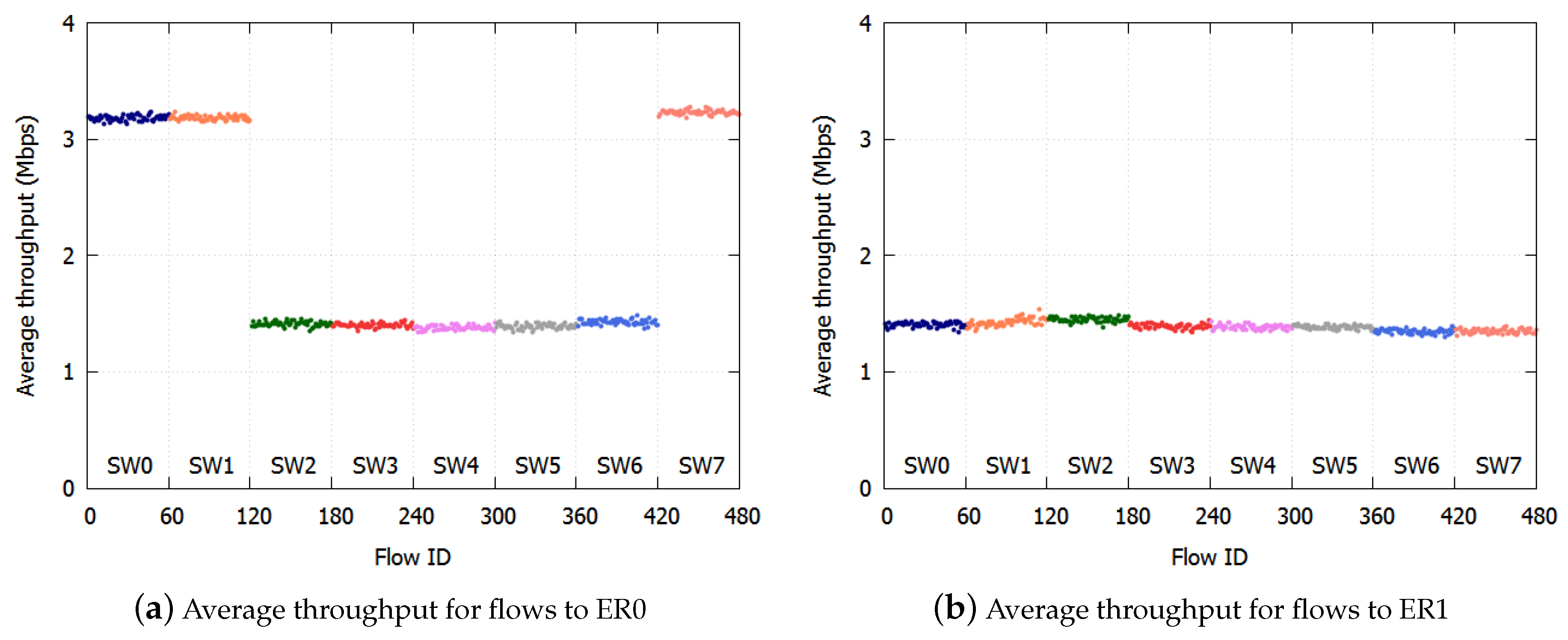
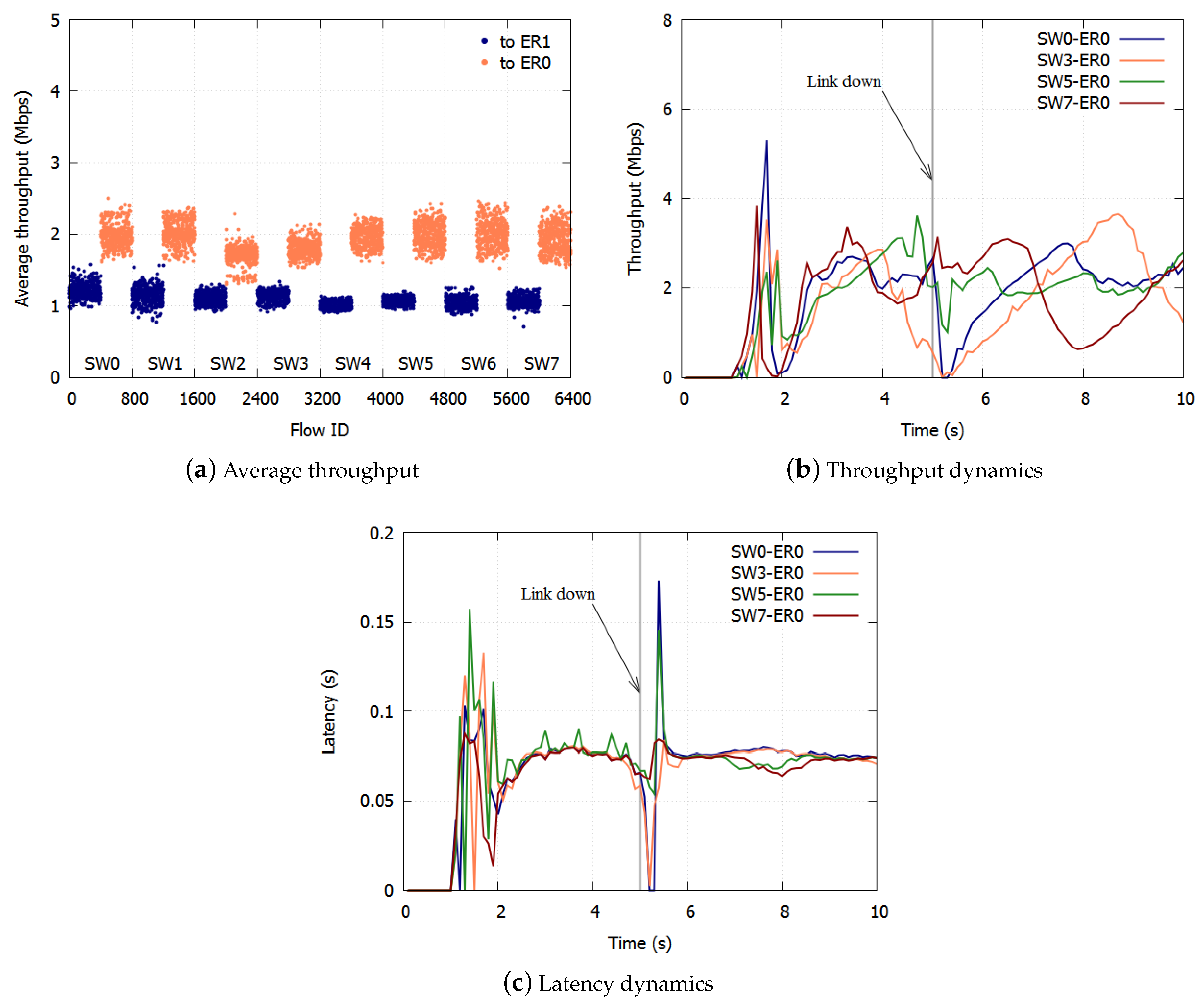
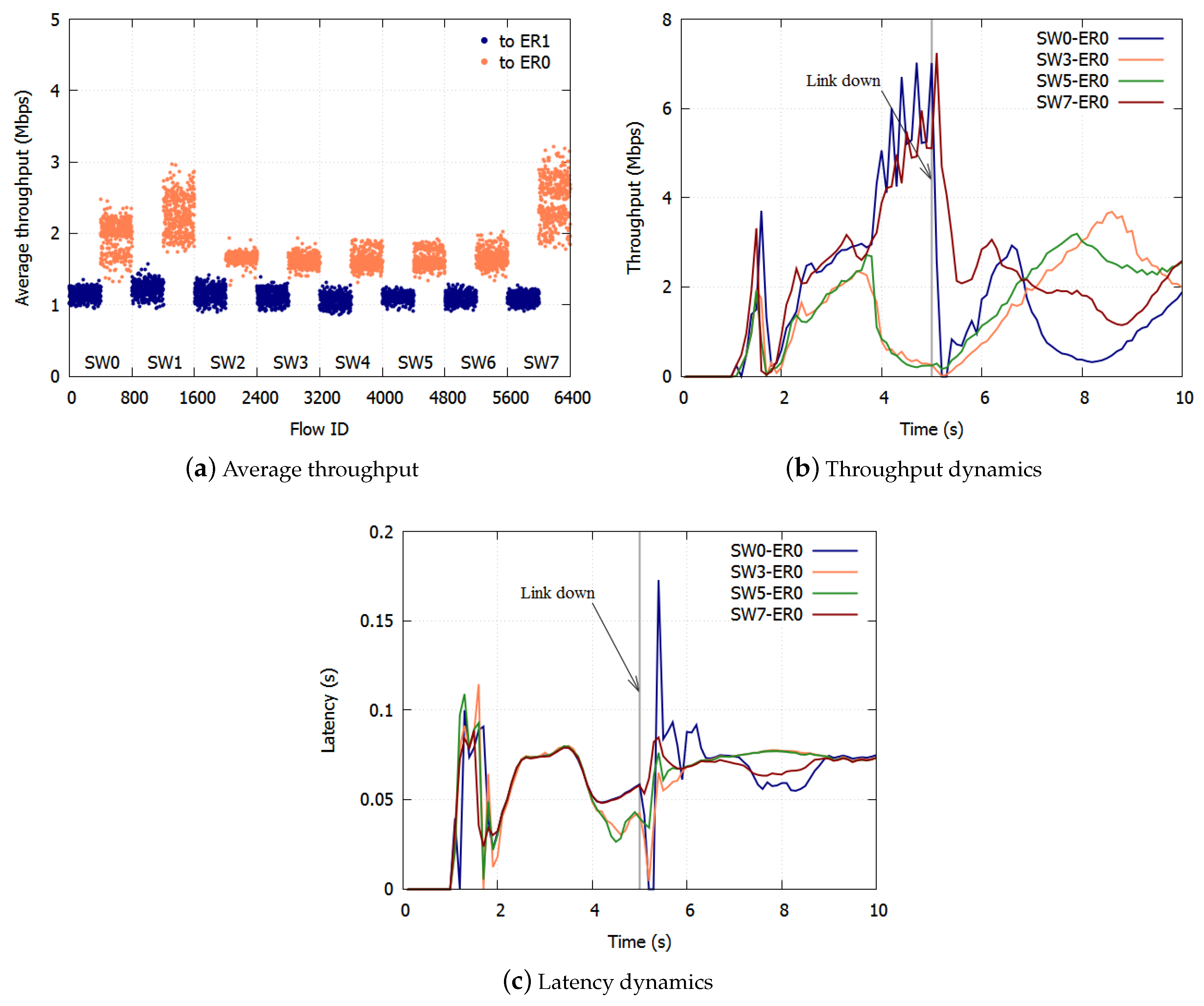
1. Introduction
In current networks, bufferbloat is a prevalent problem [
1]. The presence of bufferbloat in 3G/4G cellular networks was confirmed in [
2]. Bufferbloat refers to the phenomenon of excess buffering of frames and the high latency and low throughput caused by it [
3]. This is an increasingly common problem, because the reduced cost and high capacity of memory are leading to more buffers loaded in network equipment. The impact of buffer sizing on Internet services was examined in [
4] in view of Quality of Experience (QoE) to show that bufferbloat seriously degrades QoE if buffers are oversized and sustainably filled. The interaction between buffering and various TCP congestion-control schemes in cellular networks was also investigated in [
5]. For low extra delay background transport (LEDBAT) [
6], a monitoring method for upstream queuing delay was proposed to detect bufferbloat [
7].
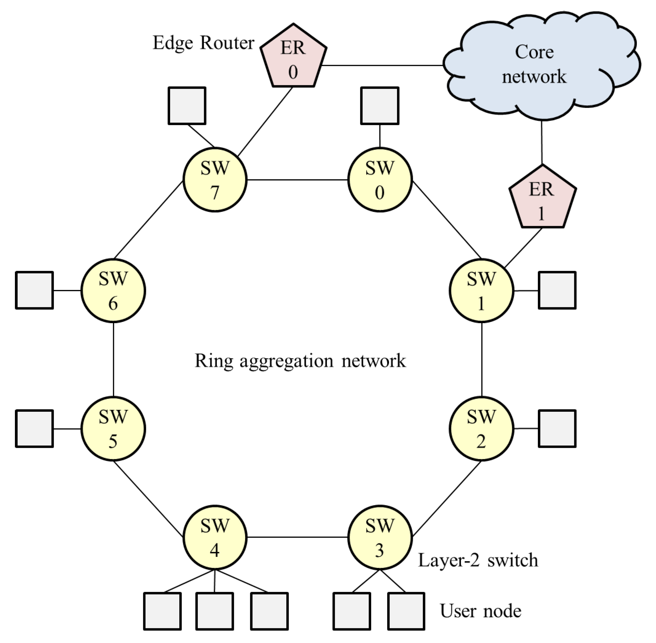
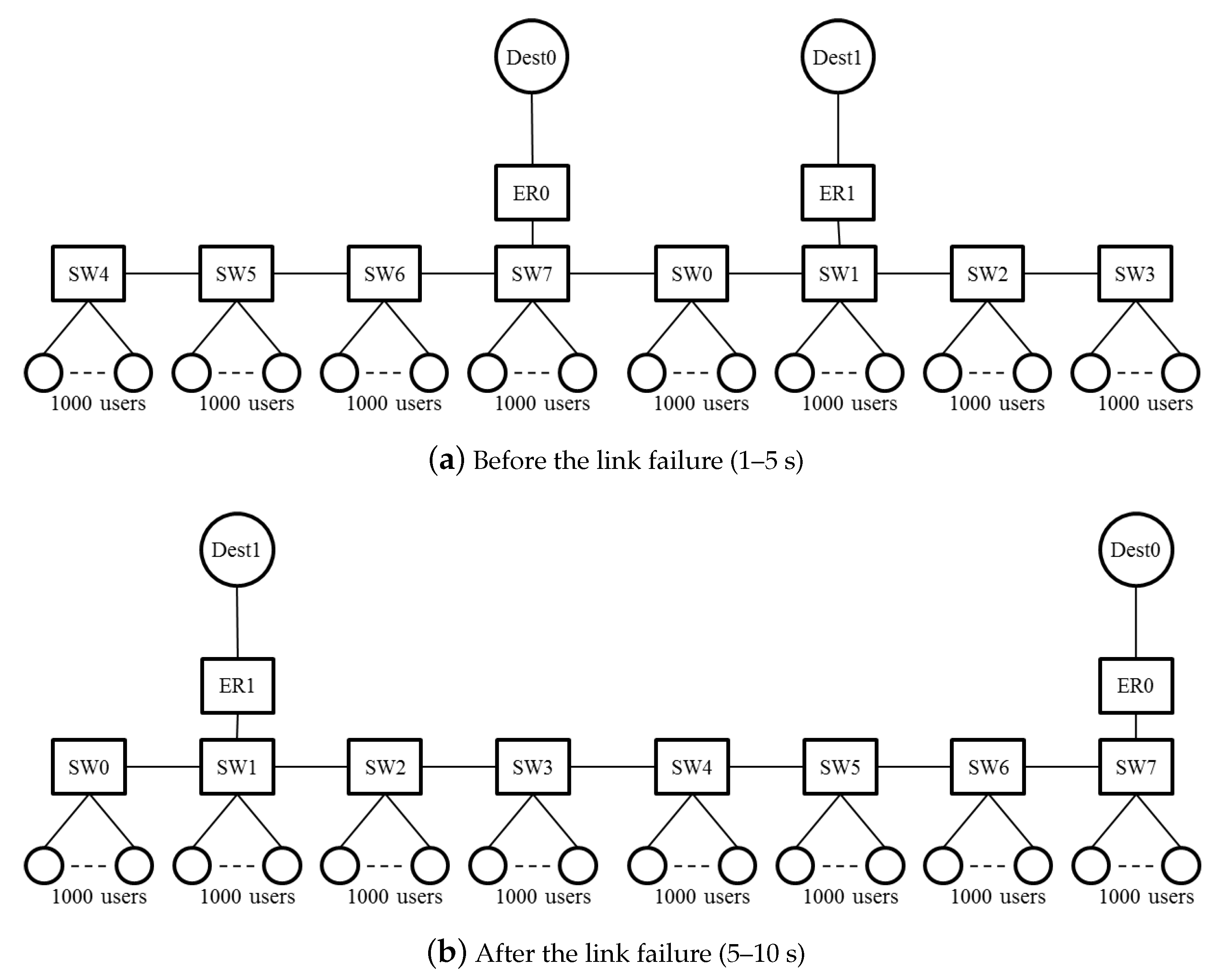
In carrier networks, a ring aggregation shown in
Figure 1, is an efficient and widely-used topology for forwarding traffic from widely-distributed user nodes to a core network. A Layer-2 ring with Ethernet Ring Protection (ERP) [
8] is a popular topology for carrier networks [
9]. A ring topology consists of Layer-2 Switches (SWs), and Edge Routers (ERs) are connected to the SWs. This network easily suffers from bufferbloat, however, because user traffic is forwarded along multiple ring nodes. If numerous user nodes are connected to SWs, the aggregated traffic to an ER can become congested. The queuing delay increases while throughput decreases in accordance with the number of SWs that the flow traverses. Thus, a fairness scheme is required in ring aggregation to achieve per-flow throughput fairness and bufferbloat avoidance, because frames are forwarded along multiple SWs.
To overcome bufferbloat, the Active Queue Management (AQM) approach has been reconsidered to control the queuing delay, such as Controlled Delay (CoDel) [
10]. A Proportional Integral controller-Enhanced (PIE) scheduler [
11] was also proposed to control the average queuing latency. The goal of these AQM schemes is overcoming bufferbloat; not per-flow fairness. To achieve per-flow fairness, Fair Queue CoDel (FQ CoDel) is developed as CoDel with Fair Queueing (FQ) [
12]. With FQ CoDel, incoming traffic is divided into flows, and each flow is put in a separate queue. However, the deployment of per-flow queuing in high-speed networks is complex and costly.
The resource allocation problems have been intensely studied for various networks. In [
13], the problem of joint utility-based customized price and power control in multi-service wireless networks was investigated using S-modular theory. The authors of [
14] made suboptimal solutions according to iterative methods for a resource allocation problem with partial fairness considering weighted sum throughput maximization in an orthogonal frequency-division multiple access system. For joint users’ uplink transmission power and data rate allocation in multi-service two-tier femtocell networks, a distributed and iterative algorithm for computing the desired Nash Equilibrium was introduced [
15]. In [
16], a user association method to maximize the downlink system throughput in a cellular network was proposed. To achieve per-flow fairness and bufferbloat avoidance in ring aggregation networks, N Rate N + 1 Color Marking (NRN + 1CM) was proposed [
17,
18,
19]. Colors are assigned to frames based on input rate, and frames are discarded according to their color and a frame-dropping threshold, which is shared by SWs through a notification process. The performance of NRN + 1CM was confirmed through mathematical formulation and computer simulations; per-flow fairness can be achieved regardless of traffic types, the number of SWs and buffer sizes. However, previous works focused on a logical daisy chain topology with a single ER. The currently available threshold notification process of NRN + 1CM cannot be employed for ring networks with multiple ERs.
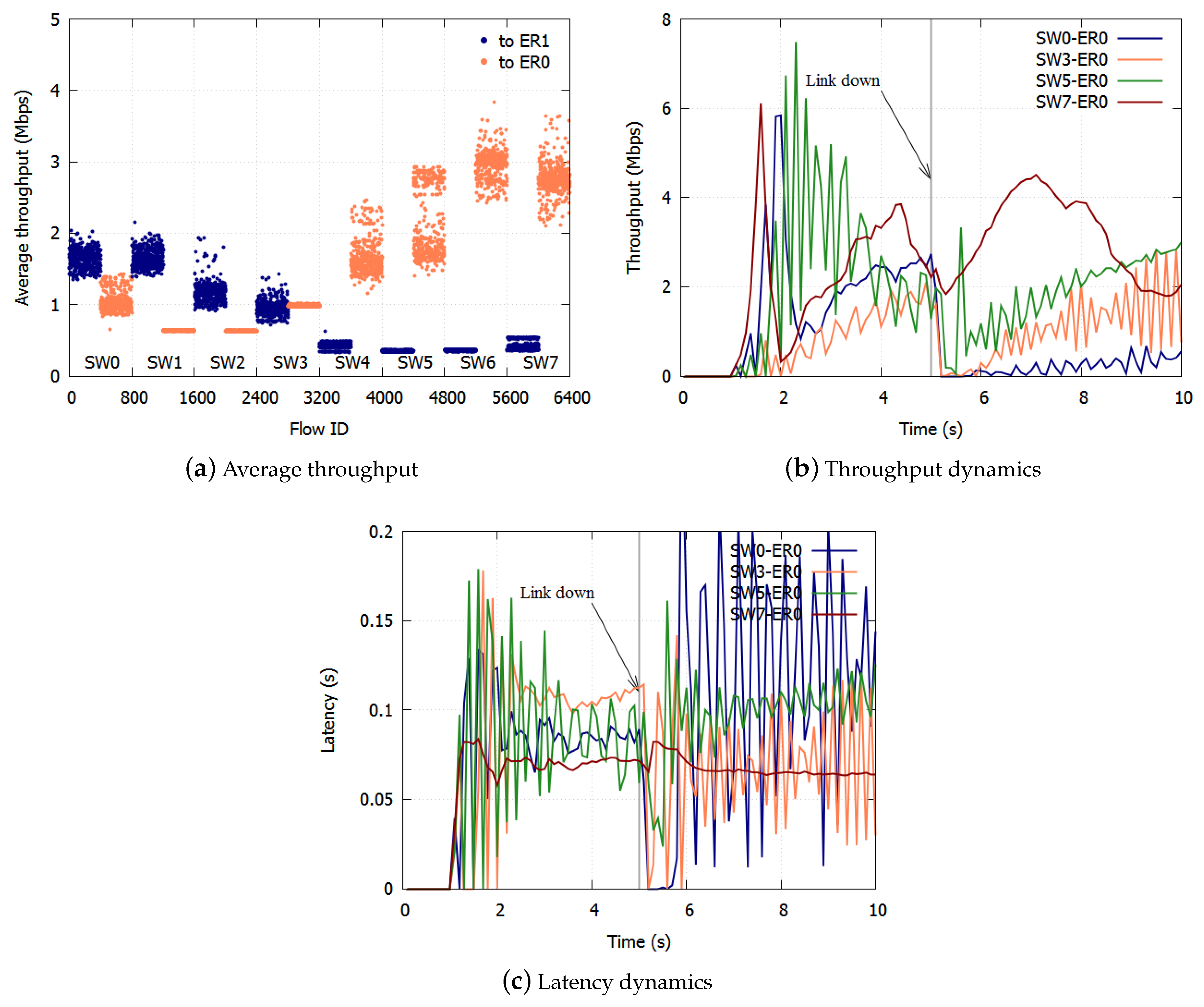
Therefore, this paper proposes a method for applying NRN + 1CM to a ring aggregation network with multiple ERs. We also show the resilience of fairness after a link failure. The rest of the paper is organized as follows.
Section 2 describes the overview of NRN + 1CM and the problems with existing algorithms.
Section 3 describes the proposed algorithm. In
Section 4, we evaluate the effect of the proposed algorithm with computer simulations. We provide our conclusion in
Section 5.
2. NRN + 1CM
2.1. Overview
Here, NRN + 1CM is briefly described in order to introduce the proposed algorithm in the next section. It was proposed in [
17] to realize per-flow fairness in ring aggregation networks. It is assumed that all the traffic to and from user nodes is transmitted via the core network and that there is no direct communication between user nodes , which is a common situation for IoT applications. The concept for NRN + 1CM is outlined in
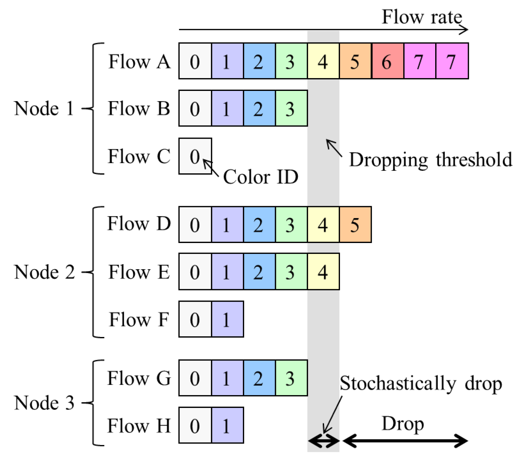
Figure 2, and the architecture of an SW to employ it is shown in
Figure 3. Flows forwarded from another SW are called transit flows, and other flows are called station flows. Express class traffic is transmitted first by Priority Queuing (PQ). The transit Best Effort (BE) frames are directly forwarded to a dropper, and the station BE frames are forwarded to per-station flow markers. They are marked with a color that indicates its dropping priority. Colors are assigned according to the input rate. More colors are used for high-rate flows. For example, eight colors are available in
Figure 2. After the color marking, they are sent to the dropper. At the dropper, frames are selectively discarded on the basis of a dropping threshold and the frame color. Undropped frames are enqueued in a BE queue. The dropping threshold is shared with the SWs. Consequently, per-flow throughput fairness is achieved. Details for the marking, frame drop and threshold notification are described in the following subsections.
2.2. Marking
A per user marker marks a BE frame with a color. Let s denote a flow identifier. A marker updates a marking threshold () with a token bucket. Let denote the number of tokens and B denote the bucket length. Let and denote the number of reset tokens. Initially, and . increases at a token-accumulation rate w. If , then is decremented, and is set at . When a frame of length L arrives, is used by . If , then is incremented, and is set at .
After a marker receives a frame and updates
, the initial marking value
is generated. The probability of
(
) is calculated as follows:
Then,
is translated to the marking color
n with:
where
(
) is a parameter. The generated color
n is marked for the incoming frame. Since
increases in accordance with the flow input rate, more colors are used for high rate flows. Let
denote the input rate of frames colored with
n for one flow. If
n is fixed,
is constant for all flows.
2.3. Frame Drop
The colored frames are forwarded to the dropper. It decides whether to transmit or discard frames based on their color. Let integer
M (
) denote the dropping threshold and
P (
) denote the dropping probability. The frame is discarded if
. Accordingly, the number of discarded colors increases in proportion to
M. If the frame belongs to station flows, frames with
are discarded with a probability
P, and they are transmitted with a probability
. Since
M increases in accordance with the current queue length, which is described in detail in
Section 2.4, the number of discarded colors increases as the congestion becomes heavy. After this process, frames that have not been discarded are forwarded from the SW.
2.4. Threshold Notification
SWs perform a cyclical frame-dropping threshold-notification process. Let m denote a local threshold, p denote a local probability, denote a notified threshold and denote a notified probability.
First,
m and
p are calculated locally based on the current queue length
q and the capacity of the queuing system
Q. Here,
m is calculated as follows:
where
is a positive integer. Moreover,
is defined as
. If
in (
3),
is satisfied. With
,
p is calculated as follows:
Second,
is updated with
and
through the notification process. After this update process,
is sent to the upstream SW. The update procedure is as follows. Let
denote the length of the cycle interval. The most downstream SW sends
to an upstream SW with a notification message at every
. When this upstream SW receives the message, the dropper is notified of
. Then, the dropper updates
by comparing
and
as follows:
For the most downstream SW, is employed, because and are always zero. By repeating this process, the thresholds are propagated to all SWs in the network, and of all ring SWs is updated.
In a ring aggregation network, station flows join transit flows at each SW, and they are forwarded to an edge SW. When an SW does not receive station flow, the SW simply transmits transit flows. The number of flows and the number of enqueued frames are greater at downstream SWs receiving station flows. The most downstream SW receiving station flows is defined as the most congested SW. Therefore, M and P for the most congested SW are shared and used by every SW after the threshold-notification process.
2.5. Problems with NRN + 1CM
However, the system configuration employed in the study so far (
Figure 3) focuses on a logical bus topology in which an ER is connected to the most downstream of the cascaded SWs. In particular, in carrier networks that are required to provide high reliability, a ring aggregation topology with multiple ERs (
Figure 1) is widely employed. The existing NRN + 1CM cannot be employed in such networks because it does not assume multiple ERs and switching paths. It is important to enable NRN + 1CM to realize fairness in ring aggregation networks with multiple ERs.
The problems that exist with multiple ERs are as follows. Traffic from users is transmitted to any ER via the SWs in the ring. User traffic joins and branches at the SWs, because traffic bound for different ERs coexists in the same link. Moreover, traffic from ERs to users joins and branches at the SWs. The congestion state differs at each link. If each SW simply employs the dropping threshold received from another SW in such situations, the discarding of too many frames leads to the underutilization of links.
As an example, we assume that in
Figure 1, the SW1-SW2 link is blocked, and at SW7, two colors (
) are transmitted to ER0 and three colors (
) to SW0. SW6 receives the dropping thresholds of both paths from SW7. If SW6 employs a large value as in
Section 2.4, only two colors (
) of frames are transmitted to SW7. All frames whose color satisfies
are discarded. The accumulation of the queueing delay is suppressed, but the frames to SW0 are over discarded and the links underutilized.
With ERP, paths are switched on link failures. After the failed link has been blocked, the Ring Protection Link (RPL) is unblocked, and the ring recovers in 50 ms. The transmission routes of the traffic change on the switching paths. Traffic control has to be deployed again based on the new topology.
3. Proposed Algorithm
3.1. Concept
We propose a method for applying NRN + 1CM to a ring aggregation network with multiple ERs. With the proposed algorithm, to avoid discarding too many frames, an SW dynamically selects the dropping threshold to send. If frames from the adjacent SW are transmitted to multiple ports at the SW, the SW selects the dropping threshold of the less congested port and notifies the adjacent SW of the selected value. Frames are not over discarded when we use the dropping threshold of the less congested port. If frames from the adjacent SW are transmitted to a single port at the SW, the SW selects the dropping threshold of the most congested port, because in this case, frames cannot be over discarded.
We describe this with the same example shown in
Figure 1. At SW7, two colors (
) are transmitted to ER0 and three colors (
) are transmitted to SW0. SW7 selects the dropping threshold of the port linked to SW0, because it is the less congested port. SW6 receives the dropping thresholds of the port to SW0 from SW7. Three colors (
) of frames are transmitted to SW7. Frames whose color satisfies
are discarded at SW6.
With the proposed algorithm, the accumulation of the queueing delay is suppressed, and there is no underutilization of links because frames are not over discarded. The selected threshold notification is described in detail in
Section 3.3. On link failures, each queue discards all frames and initializes the dropping threshold and the dropping probability. The SWs equalize the bandwidth again in the new topology.
3.2. Node Architecture
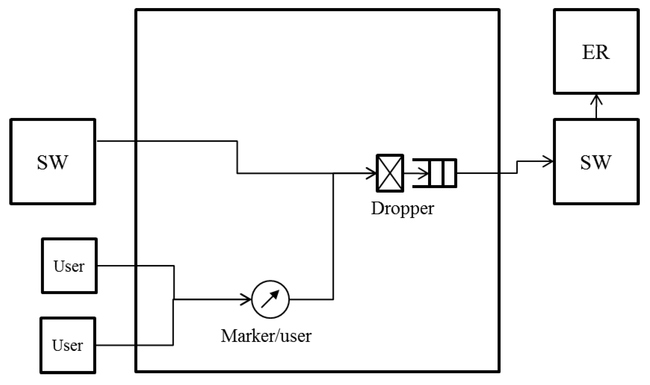
The node architecture for operating the proposed algorithm is shown in
Figure 4.
Figure 4 shows an SW that is connected to an ER and whose links to adjacent SWs are not blocked. At an SW that is not connected to an ER, the queue to the ER is not used. When either of the links to adjacent SWs is blocked, the link does not transmit any data frame. Only BE queues are shown in
Figure 4. The SW has a queue to the ER
and queues to adjacent SWs
,
. Each queue uses a dropper. The frames coming from users are marked with colors by the per user marker. The frames arriving from the ER are assumed to be marked with colors in the same way. The marked frames are divided and transmitted to the queues based on their destination.
3.3. Selected Threshold Notification
We describe the selected threshold notification in detail focusing on . can be described in the same way with the right side on the left. Let denote the larger value of a and b.
Of all the frames queued into
, the accumulation of queueing delay occurs for the frames coming from the left SW in
Figure 4. We call this left SW in
Figure 4 the opposite SW, because it is connected to the reverse port of the ring from
. The frames transmitted from the opposite SW are queued into
or
or are transmitted to the users based on their destination node.
and
can be congested.
The droppers of
and
calculate the dropping threshold and the dropping probability with the queue length. Let
and
denote the calculated values. The values received from the right SW in
Figure 4 are described as
. When deciding whether or not to discard frames,
always uses
, and
uses
.
The SW has flags and for the selected threshold notification. and are the flags for the frame division of each output port. If a frame from the opposite SW is transmitted into , is set at . If it is transmitted into , is set at . The dropping threshold and the dropping probability are sent to the opposite SW cyclically. The interval of the cycle is . If and are both , is selected. Otherwise, is selected. After the notification, all flags are set at . If the port is blocked, the notification process is not performed.
With this algorithm, if frames from the opposite SW are transmitted to multiple ports, the SW selects the dropping threshold of the less congested port and notifies the opposite SW of the selected value. Frames are not over discarded when the dropping threshold of the less congested port is used. If frames from the opposite SW are transmitted to a single port, the SW selects the dropping threshold of the most congested port, because in this case, frames cannot be over discarded. The accumulation of the queueing delay is suppressed, and the underutilization of links does not occur because frames are not over discarded.
5. Conclusions
In this paper, we proposed a method for fair bandwidth sharing with NRN + 1CM in a ring aggregation topology with multiple ERs. To equalize the bandwidths of users with a simple queue configuration, we proposed NRN + 1CM, which is a multicolor marking algorithm. However, the system configuration studied thus far is a logical bus topology in which an ER is connected to the most downstream of the cascaded SWs. In reality, a ring aggregation topology with multiple ERs is widely employed to provide high reliability especially in carrier networks. The existing NRN + 1CM cannot be employed in such networks because it does not assume multiple ERs and switching paths. If each SW simply employs the dropping threshold received from other SW in such situations, the over discarding of frames leads to the underutilization of links.
We proposed a method for applying NRN + 1CM to a ring aggregation network with multiple ERs. With the proposed algorithm, to avoid the over discarding of frames, an SW dynamically selects the dropping threshold to send. If frames from the opposite SW are transmitted to multiple ports at the SW, the SW selects the dropping threshold of the less congested port and notifies the opposite SW of the selected value. Frames are not over discarded by using the dropping threshold of the less congested port. If frames from the opposite SW are transmitted to a single port at the SW, the SW selects the dropping threshold of the most congested port, because in this case frames cannot be over discarded.
With the proposed algorithm, the accumulation of queueing delay is suppressed and there is no underutilization of links because frames are not over discarded. With respect to link failures, each queue discards all frames and initializes the dropping threshold and the dropping probability. The SWs equalize the bandwidth again in the new topology. We confirmed the effect of the proposed algorithm with computer simulations.
The limitation of current NRN + 1CM is that the performance depends on the number of available bits in the frame header. Determining the messaging protocol between SWs used for the notification process will constitute future work.
