Article

In-Hole Measurements of Flow Inside Fan-Shaped Film Cooling Holes and Downstream Effects

Department of Mechanical Engineering, Loyola Marymount University, Los Angeles, CA 90045, USA
Int. J. Turbomach. Propuls. Power 2024, 9(4), 36; https://doi.org/10.3390/ijtpp9040036
Submission received: 21 June 2024 / Revised: 18 October 2024 / Accepted: 7 November 2024 / Published: 2 December 2024

Abstract

:
The study of low-speed jets into crossflow is critical to the performance of gas turbines. Film cooling is a method to maintain manageable blade temperatures in turbine sections while increasing turbine inlet temperatures and turbine efficiencies. Initially, cooling holes were cylindrical. Film cooling jets from these discrete round holes were found to be very susceptible to jet liftoff, which reduces surface effectiveness. Shaped holes have become prominent for improved coolant coverage. Fan-shaped holes are the most common design and have shown good improvement over round holes. However, fan-shaped holes introduce additional parameters to the already complex task of modeling cooling effectiveness. Studies of these flows range in hole lengths from those found in actual turbine blades to very long holes with fully developed flow. The flow within the holes themselves is difficult to study as there is limited optical access. However, the flow within the holes has a strong effect on the resulting properties of the jet. This study presents velocity and vorticity fields measured using high-resolution magnetic resonance velocimetry (MRV) to study three different fan-shaped hole geometries at two blowing ratios. Because MRV does not require line of sight, it provides otherwise hard-to-obtain experimental data of the flow within the film cooling hole in addition to the mainflow measurements. By allowing measurement within the cooling hole, MRV shows how a poor choice of diffuser start point and angle can be detrimental to film cooling if overall hole length and cooling flow velocity are not properly accounted for in the design. The downstream effect of these choices on the jet height and counter-rotating vortex pair is also observed.

1. Introduction

To improve engine efficiency, the gas turbine industry is continually searching for methods to allow higher turbine inlet temperatures. Cylindrical film cooling holes have widely been replaced by shaped film cooling holes for improved film cooling performance. Traditionally, shaped holes are initially cylindrical holes that diffuse in the forward and lateral directions near the exit. Early shaped hole studies were carried out by Goldstein et al. [1], who postulated that diffused holes would perform better for two reasons. The reduction in momentum flux at the exit of the hole would decrease jet penetration and the hole could be shaped to create a Coanda effect, which would cause the jet to follow the floor instead of penetrating into the free stream. Their experiments showed increased effectiveness directly downstream of the hole and also increased lateral spreading of the coolant flow. Further studies (Heidman & Ekkad [2], Okita & Nishiura [3], and Kusterer et al. [4]) have seen the value in reducing the strength of the counter-rotating vortex pair (CVP) developed downstream of the film cooling hole. There are also drawbacks to diffused holes as both Thole et al. [5] and Ganzert et al. [6] speculate that laidback fan-shaped holes may allow hot gas ingestion along the windward edge of the hole due to the decreased exit momentum from increased expansion. Furthermore, Issakhanian et al. [7] showed significantly improved film cooling from a non-diffusing oval-shaped hole without increased exit area. Under equal conditions and equal inlet areas, the oval hole showed over two times the adiabatic film cooling effectiveness beyond five diameters downstream of the hole. This improvement resulted from better attachment of the flow to the surface despite the explicit implementation of shaping to increase Coanda effect. This study focuses on diffuser-shaped holes and examines the flow inside the film cooling holes, as well as in the mainflow, to find sources of undesirable jet behavior which may lead to decreased film cooling effectiveness on turbine blades.

2. Materials and Methods

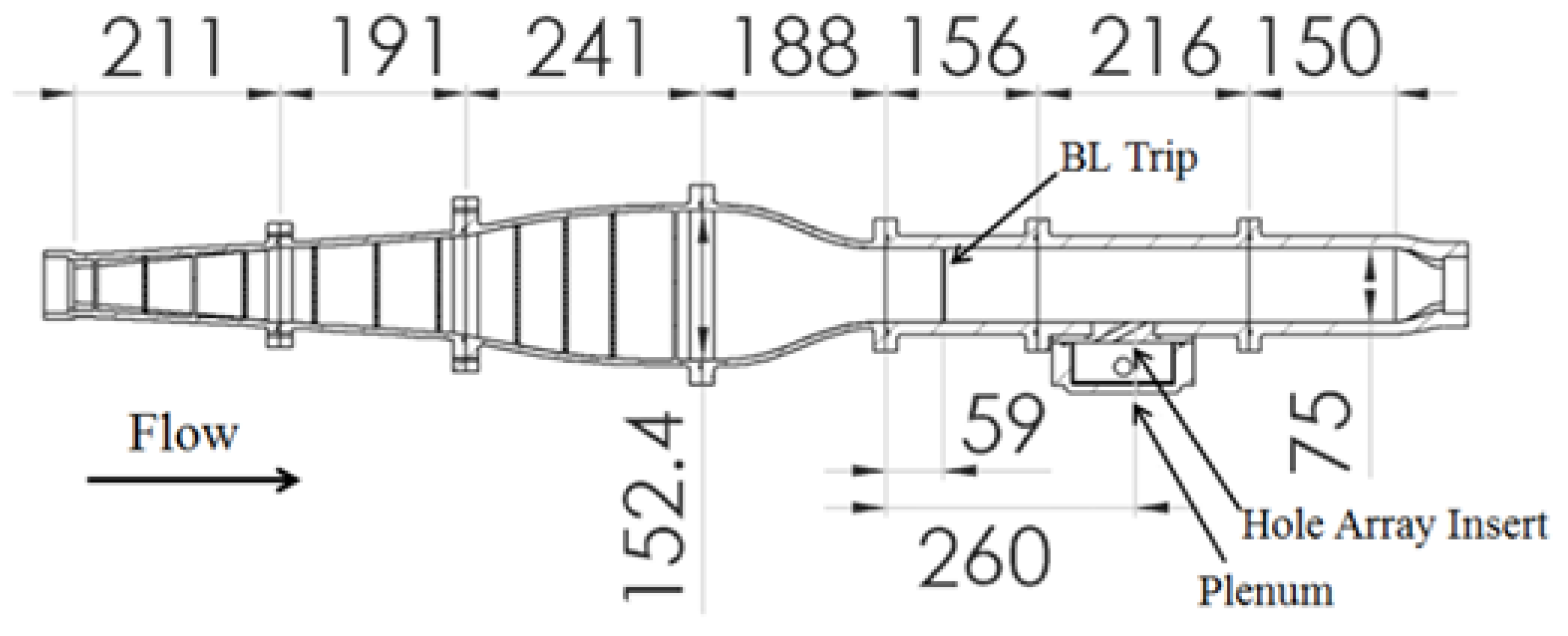
2.1. Experimental Setup

The experiments are conducted in a recirculating water channel shown in Figure 1 and previously described by Issakhanian et al. [7,8]. A set of three identical jets is introduced through a spanwise array of three cooling holes on the bottom wall which are fed by a separate supply line through a plenum. The mainflow has a bulk velocity, Ub, of 0.5 m/s, giving a bulk flow Reynolds number based on channel height of 37,500. The boundary layer momentum thickness at the hole location is approximately 0.17 D. The coordinate system has its origin at the center of the exit of the central cooling hole. X is the streamwise, Y the wall-normal, and Z the spanwise direction.
The film cooling flow is supplied from a side-fed plenum. A more detailed description of the plenum feed as well as engineering drawings are available in Issakhanian et al. [8].
The hole insert is exchangeable to allow different hole configurations. Three shapes are presented. The three shapes are variations of a fan-shaped hole and are shown schematically in Figure 2. They are herein referred to as the base diffuser-shaped hole (BDSH), the shallow diffuser-shaped hole (SDSH), and the large-mouth diffuser-shaped hole (LMDSH). All three holes are initially round with a diameter, D, of 6 mm. The film cooling holes all have a length of 6 D and inclination angle α = 30°. The baseline shape (BDSH) is defined as follows: a 30° pitched round hole begins at the plenum and extends 4.5 D, at which point it begins to expand 10° in the forward and both lateral directions until the exit. The shallow diffuser-shaped hole is also a laid-back, fan-shaped hole design similar to the BDSH. However, the shallow diffuser-shaped hole begins its expansion earlier at 2.33 D into the hole. The hole expands at an angle of 5° with respect to the inclination angle of the hole. The lateral expansion angles remain 10°. The resulting hole has an exit area similar to the base diffuser-shaped hole, but the forward expansion is more gradual and over a longer extent of the hole. The large-mouth diffuser-shaped hole is also a laid-back, fan-shaped hole design similar to the base shape. The large-mouth diffuser-shaped hole has 10° expansion in the forward and both lateral directions beginning 2.66 D into the hole. The resulting hole has an exit area larger than and reaching further downstream than both previous shapes.
The cooling hole inserts each have a single spanwise array of 3 holes with a pitch S/D = 4. The experiments are run at two different velocity ratios, Vr = 1 and Vr = 1.5. Because the working fluid is water in both flows, the density ratio is 1. Thus, the blowing ratios are 1 and 1.5, and the momentum flux ratios are 1 and 2.25.
Velocity measurements are made using magnetic resonance velocimetry (MRV) which allows for the time-averaged measurement of the three velocity components inside the 3D test field. The MRV process is similar to the method described by Elkins et al. [9]. Measurements were performed in a 3.0 Tesla GE Healthcare MRI (Milwaukee, WI, USA).

2.2. Uncertainty Analysis

Velocity measurement uncertainty as given by Elkins and Alley [9] is dependent on the encoding velocity (VENC) used during the MRI scan and signal-to-noise ratio (SNR) of the experiment as given by the following equation:
U V = 2 · V E N C π · S N R  
A typical SNR value of 80 yielded uncertainties of 0.008 m/s in the streamwise and wall-normal directions and 0.006 m/s in the spanwise direction. Table 1 below shows the SNR values for the 6 tested cases and their corresponding uncertainties. The measured flowrate for each hole was within 5% of the other holes for each case.

3. Results

The three-dimensional MRV measurements are shown here in two-dimensional slices to illustrate some of the major characteristics of the cooling flow and how it differs between hole shapes.

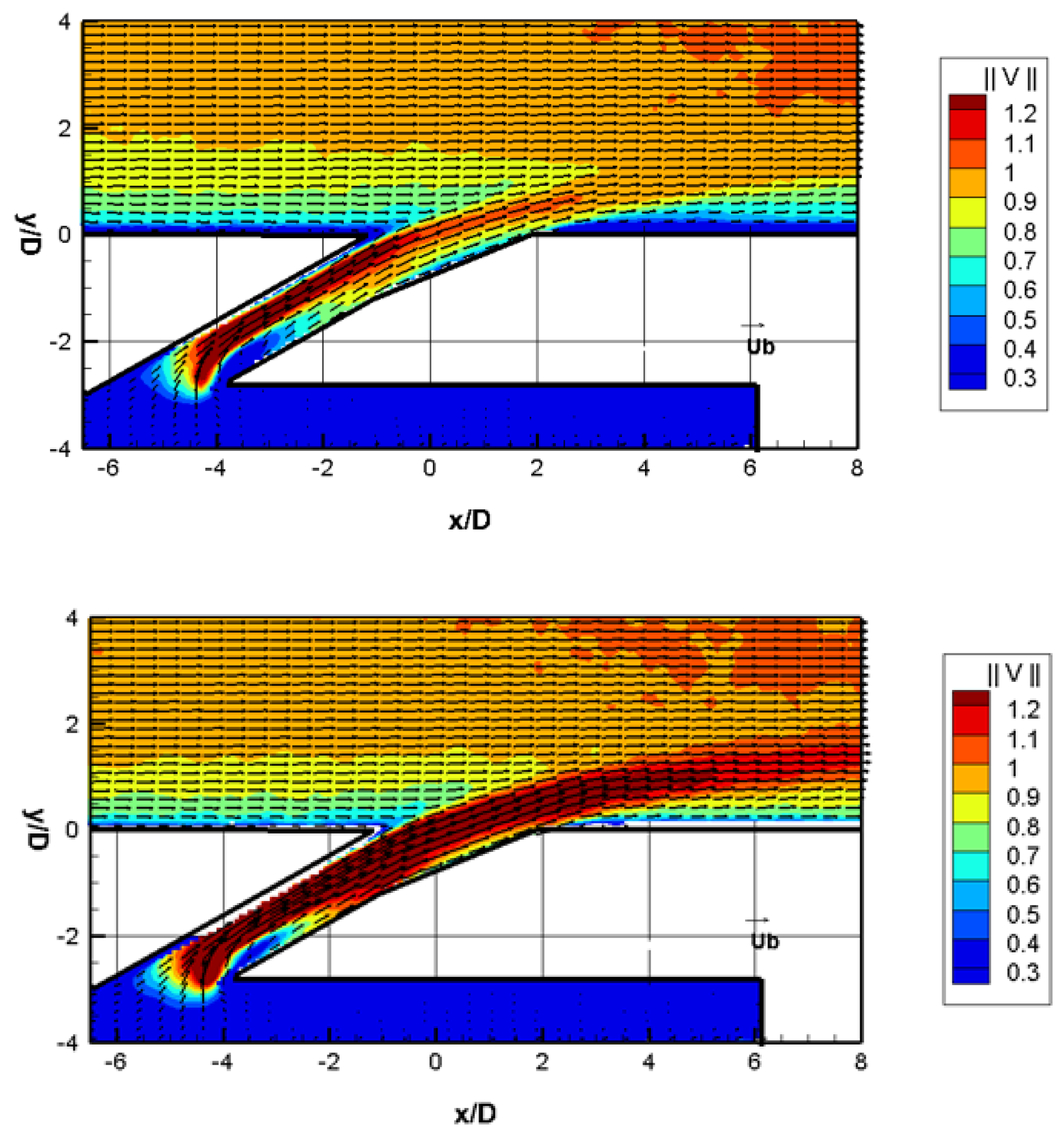
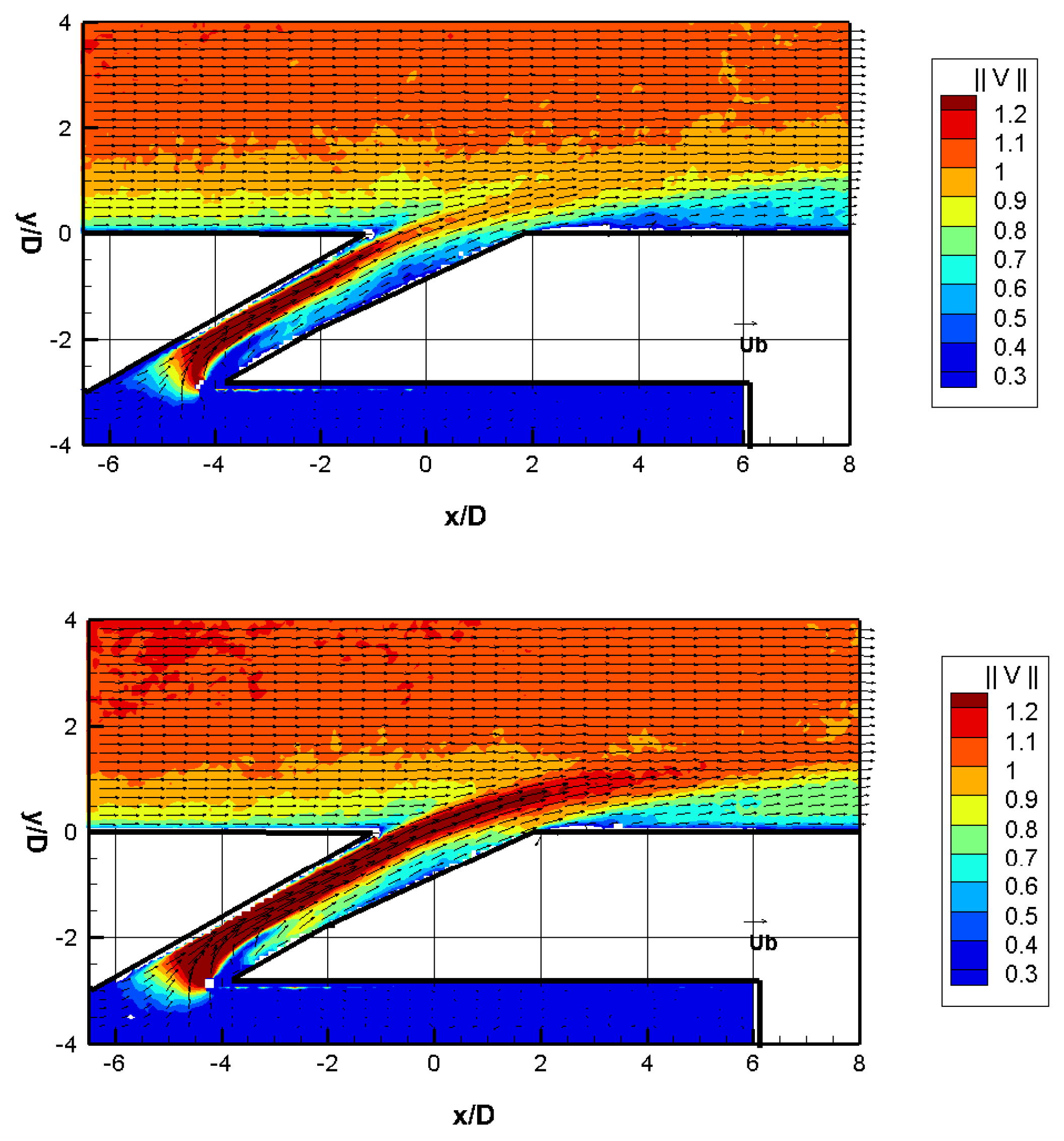
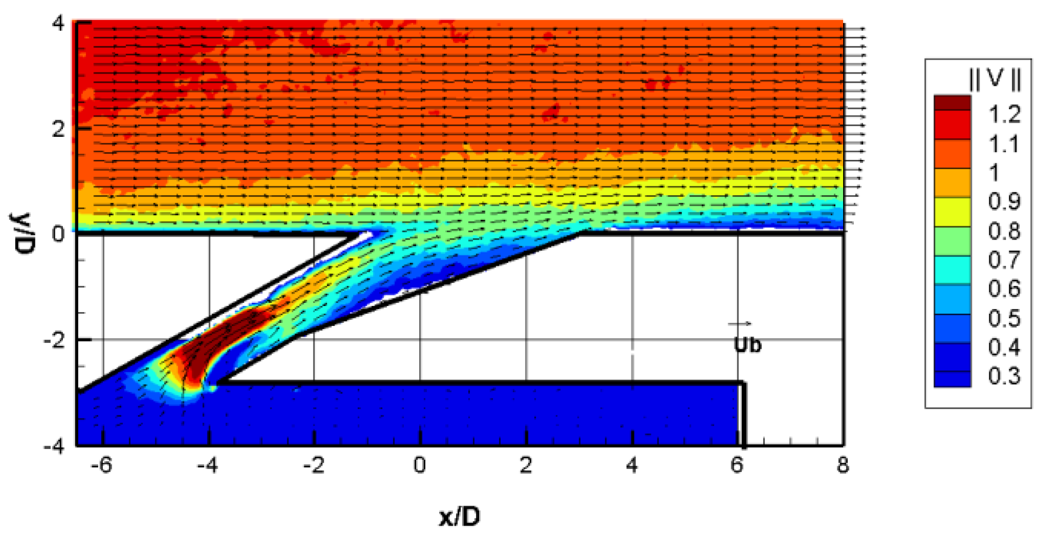
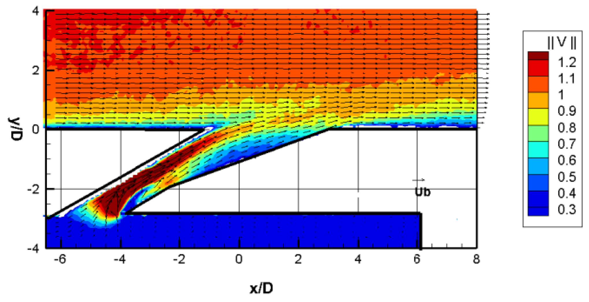
3.1. In-Hole Separation

There are two regions of likely separation in a fan-shaped diffuser hole. Because the flow entering the holes from the plenum must turn around the leeward edge of the hole, a separation bubble occurs resulting in curvature of the symmetry-plane streamlines within the hole. Unfortunately, most cooling holes will not have the length for the flow to become fully developed. The longer this non-diffusing section, the more the flow is expected to approximate a fully developed profile. Figure 3 shows the symmetry plane and a cross-section of the flow through the center hole for the BDSH at both tested velocity ratios (Vr = 1 and Vr = 1.5). It is evident that the cooling flow is much faster on the windward side of the hole.
Somewhat surprisingly, the higher velocity ratio flow seems to spread over the hole cross-section better, perhaps because of the low Reynolds number of the coolant flow at a velocity ratio of 1. Because the flow is not attached at the initiation of the diffusing section, the flow continues to jet to the exit on the windward side of the hole. The Vr = 1.5 case, which has a more even velocity profile over the extent of the hole before diffusion, again detaches at the point of diffusion.
Figure 4 shows the velocity fields in the same plane for the shallow diffuser-shaped hole cases. The hope of the shallower forward diffusion angle was that the flow would reattach before exiting the cooling hole. However, because the round section of the hole is limited to 2.66 D, the flow has even less distance over which to develop. The jetting flow on the windward side of the hole enters the diffuser section with such increased velocity that it seems to continue unaffected by the angled wall on the leeward side. These measurements are important for future shaped hole design. Schroeder et al. [10] proposed a baseline shaped film cooling hole with an equivalent 6 D hole length. Based on a literature review, they suggest a metering length of 2.5 D before the diffusion section, which is slightly less than the present case. It is seen that this length might need extending to prevent inflow asymmetry from detracting from film cooling performance.
One would expect this effect to be magnified for the large-mouth diffuser-shaped hole presented in Figure 5. However, while the flow in the round section remains highly biased to the windward side, it does quickly spread over the full cross-section at the onset of the diffusing section. This results in a much more even velocity profile over the hole exit plane, as will be discussed in the next section.

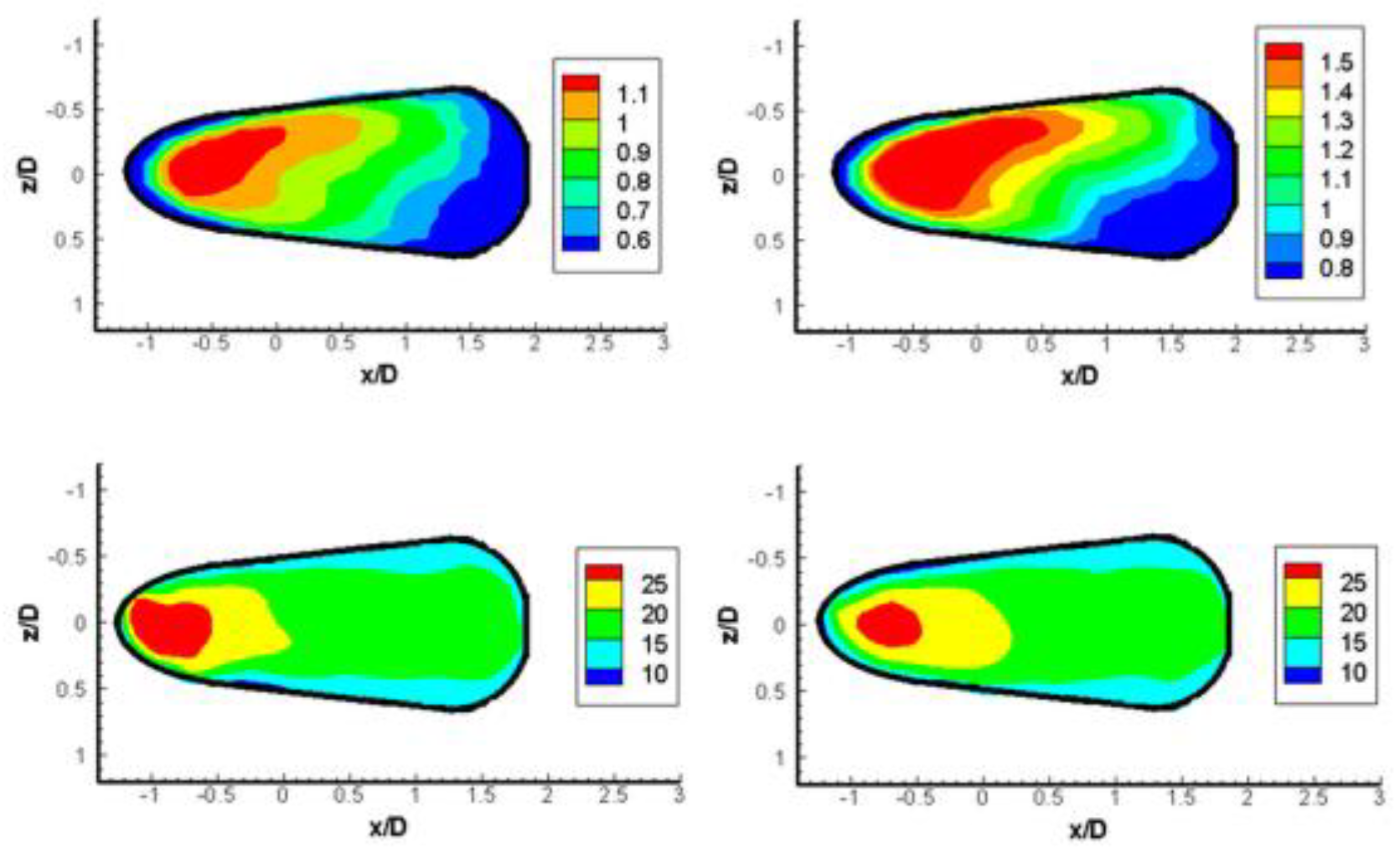
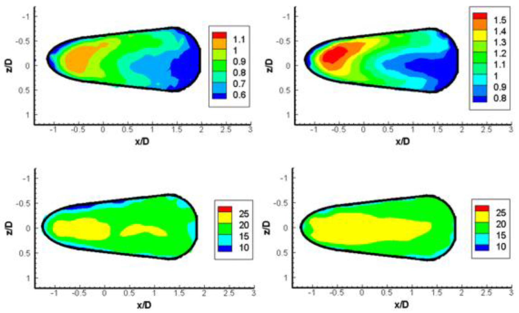
3.2. Exit Velocities

To provide higher average film cooling effectiveness, the diffusing hole is expected to provide lower momentum fluid at the hole exit and, perhaps, to provide a Coanda-like effect which keeps the coolant flow near the surface. To survey the performance of the BDSH holes in these respects, Figure 6 (top) shows the contours of hole exit velocity magnitude normalized by bulk velocity for both velocity ratio cases at the wall-normal plane just below the surface. The increased exit area will result in decreased exit velocities if the flow is spread uniformly through the hole. A heavy bias is seen towards the windward side of the exit for both velocity ratios. The “diffuser” at the end of the hole works poorly in evenly distributing the exiting flow. Further insight is available by referring back to Figure 3. The flow entering the hole separates creating a preponderance of flow on the windward side of the hole. As the flow advances through the hole, it gradually regains symmetry. However, near five diameters into the hole, where the increased expansion begins, the adverse pressure gradient from the diffusion refocuses the flow on the windward side of the hole.
Figure 6 (bottom) shows the contours of flow angle with respect to streamwise for the flow exiting the BDSH film cooling hole for both velocity ratio cases. The flow on the leeward side of the hole exits in a direction closer to streamwise. However, since the flow in that region is minimal, the effect of this tilting is minimal.
Figure 7, which plots the same values as Figure 6 for the SDSH cases, confirms that this hole shape does not improve over the BDSH in terms of even flow distribution. Furthermore, the SDSH performs more poorly in orienting the exiting jet towards the streamwise direction. The contour lines of the flow angle with respect to streamwise at the hole exit show that the values for the SDSH are higher on the downstream side of the hole than those of the BDSH.
The large-mouth diffuser-shaped hole shows improvement over both previous shapes. The exit plane velocity magnitudes in Figure 8 show that the exiting flow is slower than the bulk velocity everywhere in the hole. A possible explanation of why this more aggressive diffusion compared to the SDSH did not increase the separation within the hole is that the increased exit area was exposed to more of the wake region behind the jet where lower pressures would increase the flow rate. The contour lines of streamwise inclination angles at the exit plane in Figure 8 also show that the LMDSH does well in turning the flow in the streamwise direction. The lowered momentum of the exiting flow results in the crossflow having greater effect in turning the exiting jet streamwise.
In contrast to the fan-shaped holes, the oval hole presented in Issakhanian et al. [8] showed a largely uniform velocity profile at the hole exit. The experimental setup is identical, as is the hole inlet area. The absence of a diffusing section prevents the jetting in the upstream side of the hole. The momentum of the exit flow is not decreased, since there is no area increase. However, the high-speed flow is over a wider area and provides a thinner wall of resistance to the crossflow. The turning of the jet flow is then eased. Conversely, the wide sections on the downstream ends of the fan-shaped holes are underutilized in terms of jet dispersion.

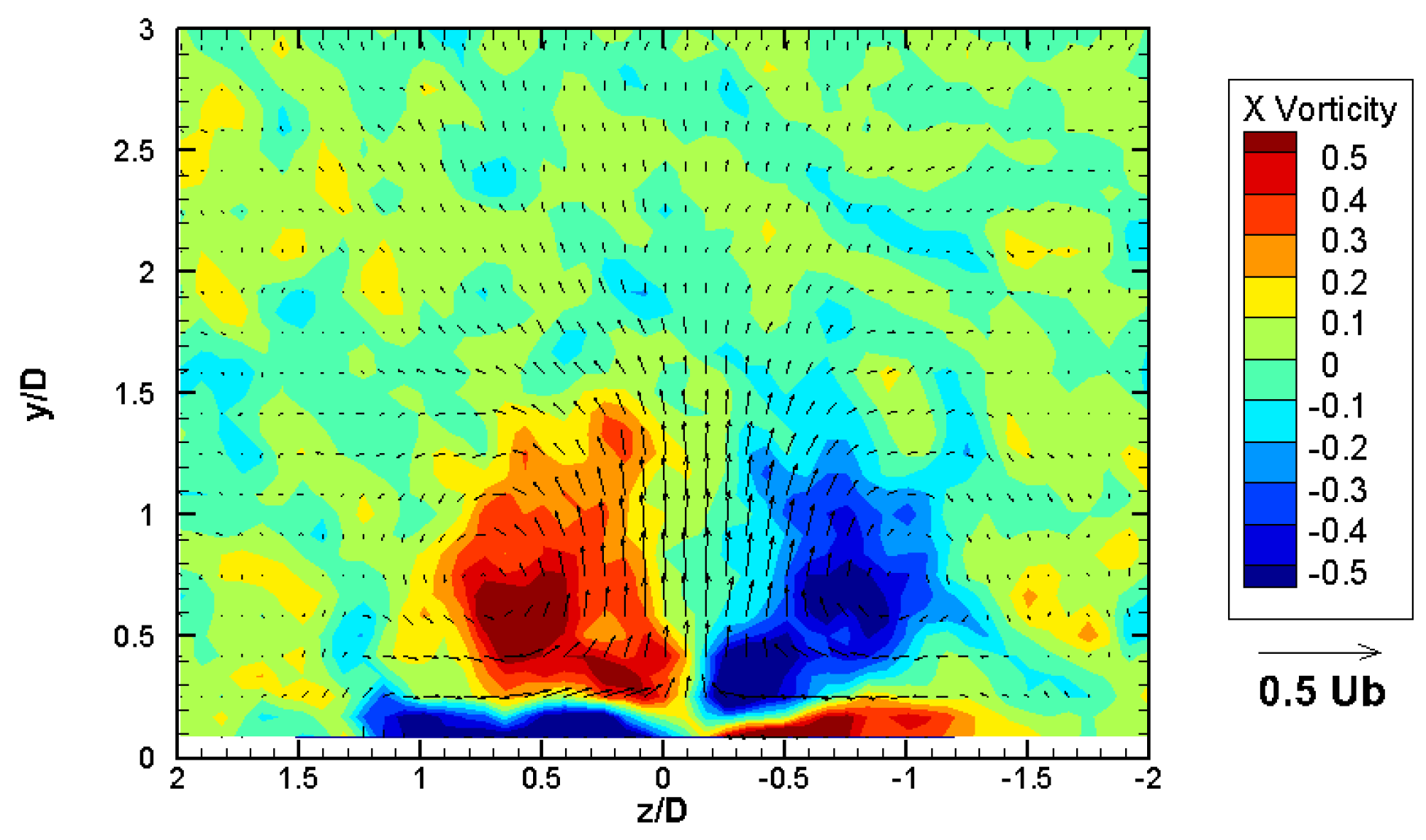
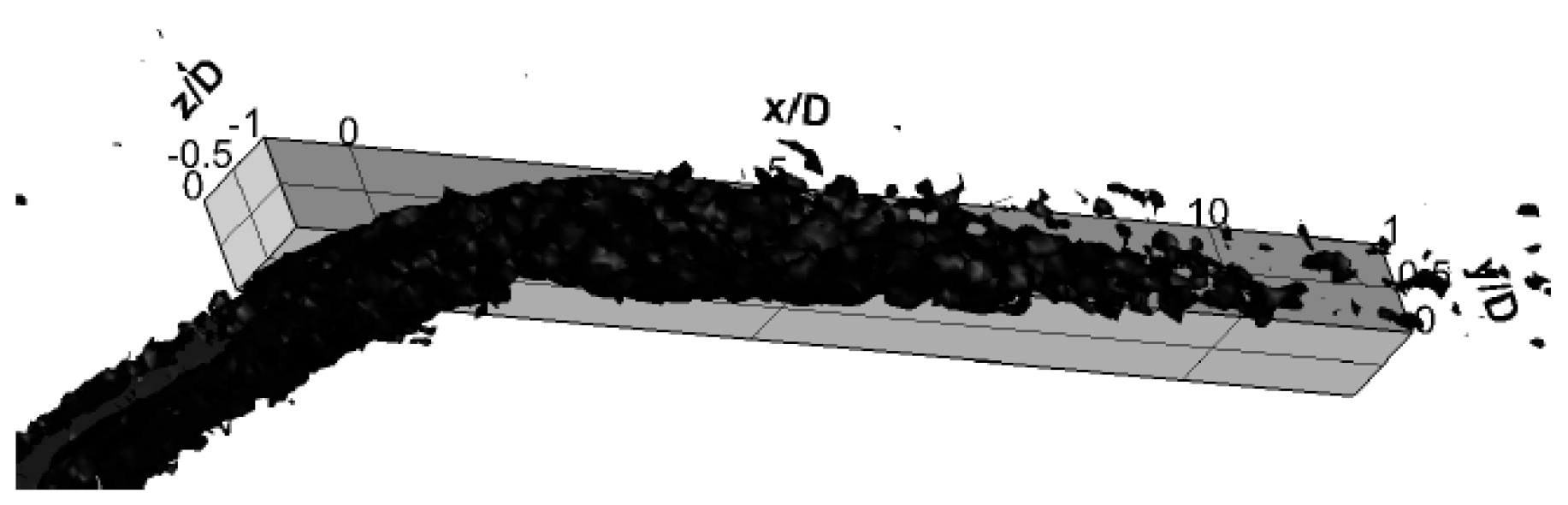
3.3. Counter-Rotating Vortex Pair

A key determinant in the effectiveness of film cooling holes is the strength and location of the counter-rotating vortex pair developed by the cooling flow. Figure 9 and Figure 10 show streamwise vorticity contours overlaid by in-plane velocity vectors for the BDSH and the LMDSH at Vr = 1.5, respectively, at x/D = 4. For the BDSH, the vortex centers are 1.6 D apart in the spanwise direction. Increased distance from the symmetry plane reduces the upwelling strength between the vortices. The SDSH had vortices at a similar distance apart, but slightly closer to the surface.
Clearly, the vortex centers of the LMDSH are further apart than the BDSH. The increased diffusion of the hole results in a larger opening not only in the streamwise, but also in the spanwise direction. The release of the in-hole vorticity at the hole lip is exposed to a widened area and results in vortices further apart from each other. As a result, the wall-normal velocities near the symmetry plane are mitigated. This indicates better cooling performance as jet liftoff is weakened.

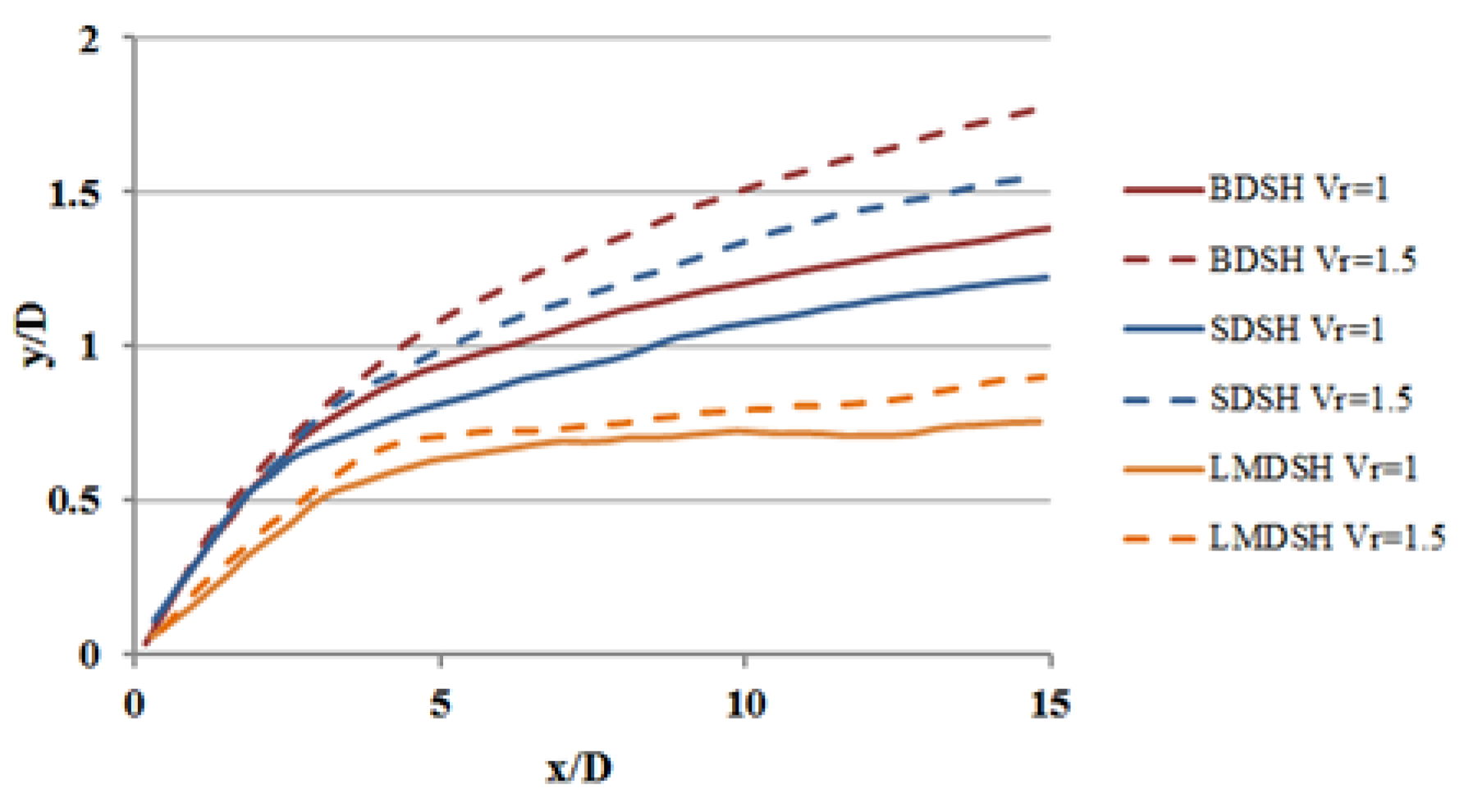
3.4. Center Streamlines
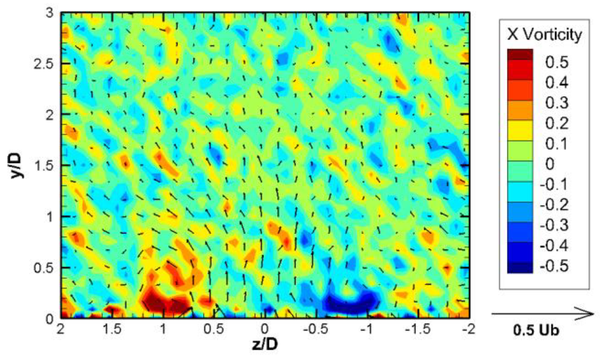
Figure 11 compares the center streamlines initiated at (x/D, y/D, z/D) = (0, 0, 0) for all six diffuser-shaped hole cases. The LMDSH significantly decreases the penetration of the jet into the mainstream, due, likely, to both the decreased injection angle of the flow at the hole exit and the weaker upwelling from the wider-spaced CVP. The velocity ratio differences do not seem to have as large an effect, especially on the LMDSH.

3.5. Vorticity

The pictured streamwise normal planes hint at differences in the vortical structures of the different shaped holes. Figure 12 shows an iso-helicity surface at threshold level—0.3 m2/s for the −Z side of the channel for the base diffuser-shaped hole at Vr = 1.5. Helicity is the dot product of velocity and vorticity. Thus, views of helicity articulate the streamwise vorticity due to the dominant streamwise velocity. Notice that the isosurface is strongly evident from the beginning of the hole up to roughly 10 D continuously. This is clear evidence that the vorticity in the mainstream is the development of the vorticity produced within the hole. Figure 13 shows the same view for the shallow diffuser-shaped hole. Notice that the helicity isosurfaces are very similar for these cases, as were the other details we observed previously.
Figure 14 show the iso-helicity surface for the large-mouth diffuser-shaped hole at Vr = 1.5. This case has a much smaller volume contained within the isosurface, indicating weaker vortices. At the hole entrance, the helicity is similar to the other two cases. The isosurface shrinks through the diffusing section of the hole and the expelled vorticity at the hole lip is much smaller than the other shapes. The extent of the iso-surface is decreased. Also, as noted by the planar view at x/D = 4, the vortex is further from the symmetry plane. The weaker vortex further from the symmetry plane suggests that this large hole will perform much better than the other two designs. Saumweber et al. [11] found no improvement in centerline effectiveness using a laidback fan-shaped hole over a fan-shaped hole with no forward expansion. The present data suggest that the increased forward expansion, and consequent increase in exit area, results in decreased harmful CVP strength and a coolant jet which remains much closer to the surface. Goldstein et al. [1] found that laidback fan-shaped holes to perform worse than fan-shaped holes, but to maintain good performance for a higher range of blowing ratios. This is supported by the smaller change in the center streamline penetration for the LMDSH cases compared to the BDSH and SDSH ones.

4. Discussion

In film cooling flows, it is the momentum of the exiting jet that determines the initial penetration height of the jet. The experiments of three different diffuser-shaped holes showed the sensitivity of the in-hole flow to the expansion angles and length of the expanding region. A short, steep expansion region results in poor diffuser performance, leading to a region of high momentum at the windward side of the hole. The shallow diffuser-shaped hole was meant to counteract this. However, a longer expansion region reduces the length of the initial round development section of the hole. For inclined holes, a significant length of round development section is needed to allow the flow to reattach after the initial turn in from the plenum or channel. This allows the cooling flow to develop towards a symmetric profile before the expansion region. If the expansion begins early, the high-momentum flow at the windward side of the hole will pass quickly through the expanding region and undergo very little diffusion. It is difficult to judge the tradeoff between a long development section and a shallow expansion from these limited cases. The large-mouth hole shows a hole with both early diffusion and steep forward expansion angle. Despite these characteristics, this shape performs well. This is likely due to the larger exit area of this design. The increased downstream exit area is thought to expose the in-hole flow to a large low-pressure region, which, contrasting with the high pressure from mainflow impingement on the windward side of the jet, evens out the flow exiting the hole. It is important to note that no entrainment of mainflow into the hole is seen in any of the cases.
These studies highlight the value of performing tests that provide a fuller representation of film cooling holes than simply measuring surface effectiveness values. Poor performance from a shaped hole can be attributed to jetting or biased flow inside the film cooling hole. Possible causes are insufficient length for fully developed flow into the hole or extreme diffusion angles. These parameters are affected by the final expansion ratio of the hole due to the downstream pressure conditions. The shaped hole studies have shown how sensitive the flow is to shape changes. Identical diffusion holes in varying locations of the turbine blade will behave differently due to the entrance length variations. Their effectiveness will also be impacted by build-up or the degradation of the hole. Avoiding the large parameter space of diffusing hole shapes is possible with clever non-diffusing holes. Non-diffusing holes which show favorable results in laboratory conditions, such as those suggested by the author in Issakhanian et al. [8], should be more robust under real-world conditions.

Funding

This research received no external funding.

Institutional Review Board Statement

Not applicable.

Informed Consent Statement

Not applicable.

Data Availability Statement

The original contributions presented in this study are included in the article. Further inquiries can be directed to the corresponding author.

Conflicts of Interest

The authors declare no conflict of interest.

Nomenclature

DCooling Hole Diameter
LLength of Hole
MRVMagnetic Resonance Velocimetry
ReReynolds Number
SHole Spanwise Spacing
UbBulk Mainflow Velocity
UvVelocity Uncertainty
VrVelocity Ratio
αEjection Angle

References

  1. Goldstein, R.J.; Eckert, E.R.G.; Burggraf, F. Effects of Hole Geometry and Density on Three-Dimensional Film Cooling. Int. J. Heat Mass Transf. 1974, 17, 595–607. [Google Scholar] [CrossRef]
  2. Heidmann, J.D.; Ekkad, S.V. A Novel Antivortex Turbine Film Cooling Hole Concept. J. Turbomach. 2008, 130, 031020. [Google Scholar] [CrossRef]
  3. Okita, Y.; Nishiura, M. Film Effectiveness Performance of an Arrowhead-shaped Film-cooling Hole Geometry. ASME J. Turbomach. 2007, 129, 331–339. [Google Scholar] [CrossRef]
  4. Kusterer, K.; Elyas, A.; Bohn, D.; Sugimoto, T.; Tanaka, R.; Kazari, M. The NEKOMIMI Cooling Technology: Cooling Holes with Ears for High-Efficient Film Cooling. In Proceedings of the ASME 2011 Turbo Expo: Turbine Technical Conference and Exposition, Vancouver, BC, Canada, 6–10 June 2011; Paper GT2011-45524. pp. 303–313. [Google Scholar]
  5. Thole, K.; Gritsch, M.; Schulz, A.; Wittig, S. Flowfield Measurements for Film Cooling Holes With Expanded Exits. In Proceedings of the ASME 1996 International Gas Turbine and Aeroengine Congress and Exhibition, Birmingham, UK, 10–13 June 1996. Paper 96-GT-174. [Google Scholar]
  6. Ganzert, W.; Hildebrandt, T.; Fottner, L. Systematic Experimental and Numerical Investigations on the Aerothermodynamics of a Film Cooled Turbine Cascade with Variation of the Cooling Hole Shape, Part 1, Experimental Approach. In Proceedings of the ASME Turbo Expo 2000: Power for Land, Sea, and Air, Munich, Germany, 8–11 May 2000. Paper 2000-GT-295. [Google Scholar]
  7. Issakhanian, E.; Elkins, C.J.; Eaton, J.K. Film Cooling Effectiveness Improvements Using a Nondiffusing Oval Hole. J. Turbomach. 2016, 138, 2016. [Google Scholar] [CrossRef]
  8. Issakhanian, E.; Elkins, C.J.; Eaton, J.K. In-hole and mainflow velocity measurements of low-momentum jets in crossflow emanating from short holes. Exp. Fluids 2012, 53, 1765–1778. [Google Scholar] [CrossRef]
  9. Elkins, C.; Alley, M. Magnetic resonance velocimetry: Applications of magnetic resonance imaging in the measurement of fluid motion. Exp. Fluids 2007, 43, 823–858. [Google Scholar] [CrossRef]
  10. Schroeder, R.P.; Thole, K. Adiabatic Effectiveness Measurements for a Baseline Shaped Film Cooling Hole. In Proceedings of the ASME Turbo Expo 2014: Turbine Technical Conference and Exposition, Düsseldorf, Germany, 16–20 June 2014. Paper GT-2014-25992. [Google Scholar]
  11. Saumweber, C.; Schulz, A.; Wittig, S. Free-Stream Turbulence Effects on Film Cooling with Shaped Holes. J. Turbomach. 2003, 125, 65–73. [Google Scholar] [CrossRef]
Figure 1. Cross-sectional view of tunnel contraction, development section, test section, feed plenum, hole insert, and outlet. All dimensions are in mm.
Ijtpp 09 00036 g001
Figure 2. Schematic of tested hole shapes: BDSH (top), SDSH (middle), and LMDSH (bottom).
Ijtpp 09 00036 g002
Figure 3. Symmetry plane velocity magnitude contours and in-plane velocity vectors for the base diffuser-shaped hole at Vr = 1 (top) and Vr = 1.5 (bottom).
Ijtpp 09 00036 g003
Figure 4. Symmetry plane velocity magnitude contours and in-plane velocity vectors for the shallow diffuser-shaped hole at Vr = 1 (top) and Vr = 1.5 (bottom).
Ijtpp 09 00036 g004
Figure 5. Symmetry plane velocity magnitude contours and in-plane velocity vectors for the large-mouth diffuser-shaped hole at Vr = 1 (top) and Vr = 1.5 (bottom).
Ijtpp 09 00036 g005aIjtpp 09 00036 g005b
Figure 6. Top: Hole exit plane velocity magnitude contour lines for BDSH at Vr = 1 (left) and Vr = 1.5 (right). Bottom: Contour lines of flow exit angle with respect to streamwise at hole exit plane for BDSH at Vr = 1 (left) and Vr = 1.5 (right).
Ijtpp 09 00036 g006
Figure 7. Top: Hole exit plane velocity magnitude contour lines for SDSH at Vr = 1 (left) and Vr = 1.5 (right). Bottom: Contour lines of flow exit angle with respect to streamwise at hole exit plane for SDSH at Vr = 1 (left) and Vr = 1.5 (right).
Ijtpp 09 00036 g007
Figure 8. Top: Hole exit plane velocity magnitude contour lines for LMDSH at Vr = 1 (left) and Vr = 1.5 (right). Bottom: Contour lines of flow exit angle with respect to streamwise at hole exit plane for LMDSH at Vr = 1 (left) and Vr = 1.5 (right).
Ijtpp 09 00036 g008
Figure 9. Contours of streamwise vorticity and in-plane velocity vectors at x/D = 4 for the BDSH at Vr = 1.5.
Ijtpp 09 00036 g009
Figure 10. Contours of streamwise vorticity and in-plane velocity vectors at x/D = 4 for the LMDSH at Vr = 1.5.
Ijtpp 09 00036 g010
Figure 11. Streamlines initiated at (x/D, y/D, z/D) = (0, 0, 0) for all six cases.
Ijtpp 09 00036 g011
Figure 12. −0.3 m2/s iso-helicity surface for the BDSH at Vr = 1.5.
Ijtpp 09 00036 g012
Figure 13. −0.3 m2/s iso-helicity surface for the SDSH at Vr = 1.5.
Ijtpp 09 00036 g013
Figure 14. −0.3 m2/s iso-helicity surface for the LMDSH at Vr = 1.5.
Ijtpp 09 00036 g014
Table 1. Diffuser-shaped hole study case space and uncertainty levels. Velocity uncertainties listed are (streamwise, wall-normal, spanwise).
ShapeVrSNRUV (mm/s)
Base180(5, 5, 4)
Base1.580(7, 7, 5)
Shallow174(6, 6, 4)
Shallow1.590(6, 6, 4)
Large-Mouth188(5, 5, 4)
Large-Mouth1.576(7, 7, 5)
Disclaimer/Publisher’s Note: The statements, opinions and data contained in all publications are solely those of the individual author(s) and contributor(s) and not of MDPI and/or the editor(s). MDPI and/or the editor(s) disclaim responsibility for any injury to people or property resulting from any ideas, methods, instructions or products referred to in the content.

