Abstract
In industrial applications such as chemical plants, cement factories, and glassmakers, large-sized centrifugal fans are commonly used for dust-laden flow processing. In many cases, the contamination is due to solid particles responsible for fouling and erosion issues. Erosion induces the reduction of mechanical resistance and, at the same time, the modification of the geometry and the surface characteristics of the internal flow path. The process works according to the characteristics of the erodent particles, such as dimension and hardness, which have to be coupled with the mechanical properties of the substrate, like hardness and roughness level. In addition to this, the intensity of the erosion depends on the dynamic characteristics of particles, especially velocity and impact angle. For these reasons, erosion-related issues are difficult predict and reduce. In an attempt to preserve the structural integrity of the internal walls, wear-resistant plates are positioned where the impacting contaminants are supposed to be more detrimental. In the present work, a combined experimental and numerical approach is proposed to evaluate the proper setup of wear-resistance plates over the flow path of a large-sized centrifugal fan. The results show how different regions (rotating and stationary walls) are subjected to different impact behavior, determining that the design of the position of the wear-resistant plate is not straightforward. Suggestions related to reducing the erosion intensity are reported, highlighting the possibility of designing the best compromise between erosion, performance, and costs.
1. Introduction
Heavy-duty centrifugal fans are employed in process industries for cement, steel, and power production. Such machines include exhausters used for different purposes: in metallurgy, they are used for agglomeration, where dust from the agglomeration process passes through them, or in heating and power plants, where ash particles are suspended in the gas flow. Usually, these machines are tailor-made to meet the customer’s requirements regarding mass flow rate and pressure, space constraints, structural requirements, etc. Most large centrifugal fans currently have an impeller diameter of 3 m to 4 m, with a power up to 4 MW and a running speed of 1000× g rpm.
The interaction of the particles with stationary and rotating components of the machine can lead to fouling or erosion. The first phenomenon refers to the adhesion of particles to the surfaces, while the second regards the progressive removal of material from some zones of the machines. The first issue is surmountable by cleaning the machine with purpose-made devices. In contrast, the second is an insurmountable issue, and overhaul operations are mandatory to restore the machine’s performance. Finally, focusing on the erosion phenomenon, since gas velocity can reach very high values, the dragged particles possess high kinetic energy that contributes to material removal from the parts where impacts occur.
Moreover, the blade-surface wear over time changes the fan geometry to one far from its design condition, reducing fan efficiency. Additionally, the erosion progression can lead to premature failures of the most affected parts if overhaul operations are postponed or even ignored. This is a severe threat to the reliability and safety of the machine. The erosion damages in stationary parts are mainly related to the efficiency and reliability of the equipment, while those on rotating parts are also associated with safety.
In 1980, the research laboratories of the Westinghouse Electric Corporation surveyed power plants having units larger than 100 MW generating capacity and using pulverized coal-fired boilers. The results of this survey are reported in a technical report from Glasser et al. [1]. The findings showed that erosion damage is located mainly on blade leading edges, trailing edges, and fan center plates. The erosion of the leading edges was the most severe one. The authors estimated that a total of 27,000 man-hours was being used annually to repair erosion damages in these machines and that the cost of purchasing replacement power during overhaul operation was around 11 million dollars per year.
Many studies investigate the erosion phenomena in heavy-duty fans through numerical simulations. For the sake of brevity, only some of them are reported. Cardillo et al. [2] studied particle erosion in a large centrifugal fan used in cement production plants. The The authors highlighted that, in such machines, the rise of secondary flows drives the dispersion of the particles toward the blades, hub, and shroud. Castorrini et al. [3] investigated the effect of erosion on an axial draft-fan employed for exhaust gas extraction in a solid-fuel power plant. The authors detected the zones most affected by particle erosion and modified the original geometry by accounting for the material removal action of the erosion process. The erosion was found to be greater in magnitude on the suction side of the blade. The numerical erosion patterns were in qualitative agreement with the on-field observations. Fritsche et al. [4] analyzed the erosion behavior of large radial fans in recycling plants for end-of-life vehicles. On the basis of CFD simulations, they showed that the impact angle of metal contaminant (1 mm particles) has a stronger influence than the impact velocity. In that case, larger volute designs (i.e., larger spiral pitch angles) were found to be preferable for reducing the erosion magnitude because the impact angle becomes steeper. Aldi et al. [5] studied the influence of damage in correspondence to the inlet bell-mouth of the fan. The numerical investigation showed that the presence of damage in that zone led to a modification of the flow field within the impeller and to the occurrence of additional damages in the fan zones where erosion issues were never observed.
A common strategy for reducing the wear issue of such machines involves using sacrificial plates designed to resist particle erosion. Wear-resistant plates are positioned in the fan zones most affected by particle erosion. Such materials are available on the market and have different costs, depending on their performance against particle wear. The selection of wear-resistant plates and their positioning within the fan is usually driven by a mix of the manufacturer’s experience and the wear-resistant material cost. Recent works [6,7] demonstrate how these sacrificial plates have a wear resistance capability related to the carbides dispersed within a cast iron matrix. Their performance is based on the ability of the carbides (chromium and niobium) to resist particle erosion and abrasion. The carbide hardness and the propensity of the matrix to absorb the impacts provided by particles reduce the detrimental effects generated by particles [6,7]. The present work combines a numerical and experimental approach to assess the erosion intensity of the machine to optimize the positioning of the wear-resistant plates within the fan. First, the wear resistance of three commercial wear-resistant plates is experimentally assessed on an on-purpose developed jet-impingement test bench. The material wear resistance was assessed using the same substrate and particles involved in the real plant to make the best erosion-magnitude prediction on the basis of numerical analysis. Then, a fluid dynamic simulation was carried out to assess the wear on the rotating and stationary parts of the machine. The division of the machine into patches aided in selecting the proper wear-resistant plate on each zone based on the local condition of erosion severity.
2. Experimental Investigation
The experimental campaign aims to characterize the erosion behavior of the materials at different impact angles and velocity values. The results of the erosion tests are expressed in terms of erosion rate (ER), which is the ratio between the target mass loss after the test and the particle mass impacted on it. Generally, the erosion rate is modeled using the following relation [8]:
where V is the particle impact velocity, α is the particle impact angle, K90 and n90 are the erosion coefficients for the normal impingement angle, and the angle function f(α) is the ratio between the erosion rate at a generic impact angle and the erosion rate at 90°:
2.1. Test Bench
The present section describes a jet-impingement test bench designed and built at the Fluid Machinery Laboratory of the Department of Engineering of the University of Ferrara. The schematic view of the whole erosion facility and the main components is depicted in Figure 1. The test bench employs dry and clean shop air provided by a screw compressor. The air is mixed with a dosed amount of powder and then accelerated in a sand-blast nozzle toward a square specimen in the test chamber. The nozzle outlet section has a diameter of 4 mm. An exhaust fan linked to a chimney recirculates the air inside the test chamber. The air mass flow rate is controlled by a pressure regulator upstream of the nozzle. The specimen is placed on a target holder, which allows an accurate regulation of tilt angle and distance from the nozzle outlet section. For the present application, a distance of 10 mm between the nozzle and the specimen surface is chosen. Preliminary tests were carried out employing alumina particles (Al2O3) (with 50 µm diameter) against 20MnB4 specimens (according to UNI EN 10269 [9]) with an elemental content as weight fraction (wt %): 0.228% C, 0.943% Mn, 0.068% Si, 0.010% S, 0.009% P, 0.025% Al, 0.003% B, 0.042% Ti, 0.070% Cr, 0.033% Ni, 0.039% Cu, 0.0001% Pb, and iron (balance). Through the preliminary tests, the reliability of the test bench was validated, since the results were in line with those provided by the ASTM G76 [10]. A detailed description of the test bench performance and usage are provided in [6,7].
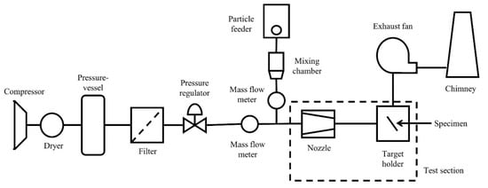
Figure 1.
Schematic layout of the experimental test bench.
2.2. Particle and Substrate Materials
The experimental tests were carried out with particle and substrate materials used in heavy-duty centrifugal fan operations. The powder used in the present application is a solid material produced as an intermediary product in the manufacture of Portland cement. It was made by sintering limestone and aluminosilicate materials, such as clay, during the cement kiln stage. The powder used in the present experimental campaign was collected directly from the plant where the fan operates. The powder morphology is depicted in Figure 2a, while its number and mass distribution are shown in Figure 2b. The particle density is 2.717 kg/m3, and its mean diameter is 4.34 µm. The Malvern Mastersizer 3000 (Malvern Panalytical, Malvern, UK) and the AccuPyc II 1340 pycnometer (Micromeritics Instrument Corporation, Norcross, GA, USA) were used to measure particle distribution and particle density, respectively.
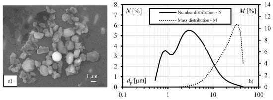
Figure 2.
Characteristics of the powder employed: (a) SEM observation, and (b) number and mass distribution.
Three commercial wear-resistant plates, named M1, M2, and M3, were tested in the present campaign:
- M1 is a layer-composite wear plate made by the open-arc welding of a flux-cored wire DIN 8555 alloy group 10 and additional metal alloy powder. Its deposit consists of primary carbides and complex carbides in a matrix of austenite and eutectic carbides. The carbide content is 62.1% (27.4% primary and 34.7% eutectic) and has the following structures: Cr7C3, Mo2C, NbC, and WC.
- M2 is a welding cladded-layer composite material with hard surfacing according to DIN 8555, alloy group 10, made with an open-arc welding procedure. The declared percentage of carbides is greater than 50%. The structures of the formed carbides are M7C3, Cr2B, and NbC.
- M3 is a nickel-based alloy rich in cast/crushed tungsten carbides (60% of the coating content). The coating is composed of Ni (37%), WC (60%), and other components (3%).
Due to their different chemical composition and properties, the erosion resistance of these materials changes accordingly. In particular, based on experienced evaluations, the M3 showed a higher wear resistance than M2 and M1.
2.3. Experimental Test Results and Model Fitting
The three materials are tested at three mean impact velocities and five impact angles (15°, 30°, 45°, 60°, and 90°). Each test is carried out with a mass flow rate of powder of 10 g min−1.
Each impact angle and velocity combination is repeated on different specimens three times. An error band, calculated following the procedure reported by Schrade et al. [11], has been used to account for the variability related to the test procedure. The experimental results are depicted in Figure 3: Figure 3a reports the ER values at normal impact angle and the interpolation lines derived from Equation (1), while Figure 3b reports the experimental values of the angle function. The M3 plate confirms the higher resistance to particle wear. M1 and M2 have comparable wear resistance. The angle function shows a clear mixture of ductile- brittle behavior of the erosion process over the impact angle: the maximum of the ER is located at almost 45°. The three plate materials show similar angle function f (α) trends.
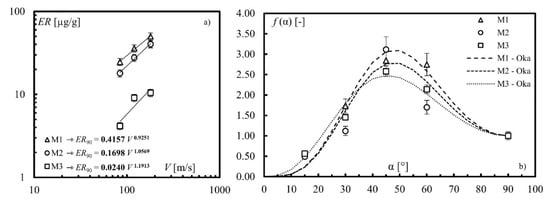
Figure 3.
Results of the experimental test: (a) erosion rate at normal impingement angle, and (b) erosion rate over the angle (experimental values and Oka’s model interpolation).
To obtain a general formulation of the angle function f(α) that can be employed in numerical simulations, the experimental results have been interpolated through Oka’s model equation [12], which calculates the angle function as a combination of trigonometric functions:
where n1 and n2 are numerical coefficients, and HV is the material hardness expressed in GPa. The results of Oka’s model interpolation are reported in Figure 3b as dashed lines, while the coefficients employed in Equation (3) are reported in Table 1 for the three tested materials.

Table 1.
Material properties and erosion coefficients of the wear-resistant plate materials.
3. Numerical Analysis
3.1. Fluid Dynamic Simulations
The fan under examination is a large-sized single-inlet centrifugal fan operating in a cement plant designed and built by Boldrocchi Group. The fan is installed in the Åalborg Portland cement plant. The fan comprises a constant-width closed impeller, 12 backward-curved single arc blades, and a constant-width spiral volute. The rear side of the impeller disk presents five radial ribs for axial thrust balancing. The impeller outside diameter is 4 m, and the fan design rotational speed is 652 rpm. An inlet box with three fixed vanes of constant thickness deflects the flow from the inlet duct, which is arranged normally to the impeller axis, into the axial direction through the fan inlet cone. The inlet cone is bolted to the front side plate of the volute, which is in common with the inlet box. Wear-resistant plates with a thickness of 10 mm are installed on the pressure side and at the leading edge of fan blades, on the inner surface of the impeller disk, on a portion of the impeller shroud near the blade trailing edge on the pressure side, and a band of the spiral volute facing the impeller outlet section. The volute and impeller of the fan are shown in Figure 4a. To characterize the internal flow field and the particle trajectories of the centrifugal fan, a 3D fluid dynamic multiphase simulation is performed at the fan actual working point in terms of mass flow rate and total pressure rise, i.e., 122 kg/s and 8300 Pa. The reader can refer to Aldi et al. [13] for all the CFD simulation setup and validation details.
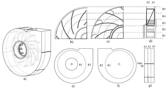
Figure 4.
The strategy of fan surface patching: (a) fan model, (b) hub, (c) shroud, (d) rotor, (e) volute front side, (f) volute back side, and (g) volute lateral side.
3.2. Strategy of Fan Surface Patching
To quantify the wear severity on specific zones, the machine is divided into patches, according to the scheme reported in Figure 4.
The impeller was divided into three zones: hub (back plate), shroud (front plate), and blades. Hub and shroud are divided according to radial discretization. The hub (Figure 4b) is divided into five annular areas, named progressively from R1 to R5, with thicknesses of 355 mm, 385 mm, 440 mm, 435 mm, and 435 mm, respectively. The shroud (Figure 4c) is divided into three circular areas named R3, R4, and R5. The sizes of R3, R4, and R5 are the same as the corresponding areas on the hub. The shroud patching also accounts for the additional wear protection plate (named TE) positioned on the trailing edge zone of the blade, in correspondence with the blade pressure side. Each blade has been divided into thirteen patches: one patch for the leading edge, six patches on the pressure side, and six patches on the suction side (Figure 4d). Both the pressure side and suction side of each blade have been divided into two axial zones (A1, and A2), and three radial zones (R3, R4, and R5). The radial division has been done following the R3, R4, and R5 divisions previously described on the hub and shroud.
The volute was divided into three main zones: the front side (inlet side), the lateral side, and the back side. The volute front and back sides were divided into two radial sectors named R1 and R2 (Figure 4e,f). The circular area named R1 is placed at the center of the volute and has a diameter of 4.40 m, slightly larger than the impeller diameter. The R2 sector comprises the remaining part of the volute front and back cases. The lateral side was divided into three axial sections (A1, A2, and A3), each of them with a thickness of 510 mm (Figure 4g). The volute cut-off is of great interest with respect to particle wear, since it is a zone that can be strongly affected by erosive processes. For this reason, the cut-off zone was isolated and analyzed separately.
4. Results
The complex flow field developed within the fan, and the high separation zone that arises, require the use of numerical simulation to predict the impact patterns on the fan components. The CFD simulation made it possible to track the particle trajectories and obtain information related to the impacts of the particles on the fan surfaces. Due to particle inertia, the impact regions are the result of the interaction between the particle trajectories and the flow field. In the present application, the particle density and diameter (see Figure 2) determine reduced particle inertia with a diffusion-inertial transportation regime of the particles [14]. Due to this, the particles follow the streamlines determining the interaction of a large portion of the fan surface with the particle impact. At the same time, the reduced inertia leads to a reduced particle kinetic energy responsible for a lower erosion rate (see [7] for more details). In the case of greater particle diameter (i.e., greater particle inertia), the impact pattern changes according to the reduced capability of the particles to follow the flow field. In this case, the most affected regions will be the impeller hub (back plate) and blade pressure side.
For the present analysis, all the internal fan surfaces are supposed to be covered with wear-resistant plates. Therefore, the wear on the fan zones is calculated by implementing Equations (1) and (3), based on the results of the CFD simulation, and using the coefficients in Table 1 for the three wear-resistant materials. The results are reported in terms of average thickness reduction (Δl) over 8000 h (almost one year) of operation on each patch of the fan.
4.1. Hub and Shroud
Figure 5 reports the thickness reduction on the shroud (Figure 5b) and the hub (Figure 5c). Based on the experimental results, M1 shows the worst performance in terms of wear resistance. Looking at the shroud, the three materials have different trends in the radial direction. This is mainly due to the different angle functions measured during the experimental tests (Figure 3b). This effect is visible when comparing M3 and M1 over R3, R4, and R5. However, higher wear intensity is found in the zone near the trailing edge, named TE. For all of the materials, the wear on the hub is high in the R1 zone, decreases in the radial direction until R3, and slightly increases towards R5. The center of the disc (R1) is critical since its positioning in front of the inlet section promotes a high impact frequency in that zone.
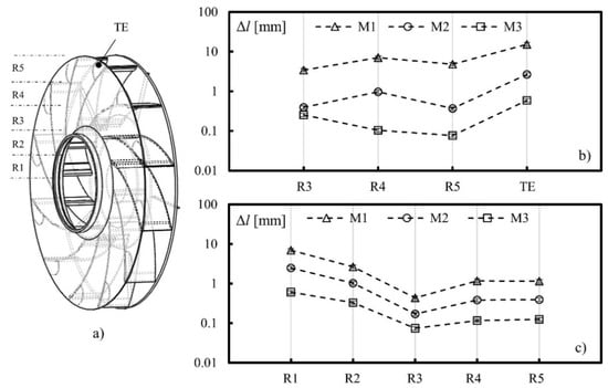
Figure 5.
Rotor wear: (a) patches coordinates and material loss, (b) on the shroud, and (c) on the hub. R1, R2, R3, R4 and R5 are the radial annular areas, TE is the trailing edge.
4.2. Blades
Figure 6 reports the results for the blade pressure side (Figure 6b,c) and suction side (Figure 6e,f). The leading edge results are included in Figure 6b. Regarding the pressure side of the blade, the wear severity decreases in the radial direction for the portion of the blade near the hub (A1) and increases in the radial direction for the portion near the shroud (A2). However, the wear on the A1 zone is more severe than A2. In particular, the leading edge is the impeller zone, which experiences high material loss. The trends of Δl for the three materials in the radial direction are similar, but shifted on the y-axis, highlighting the different wear resistance of the three plate materials. Regarding the suction side of the blade, the wear is almost uniform on the whole surface for a fixed plate material.
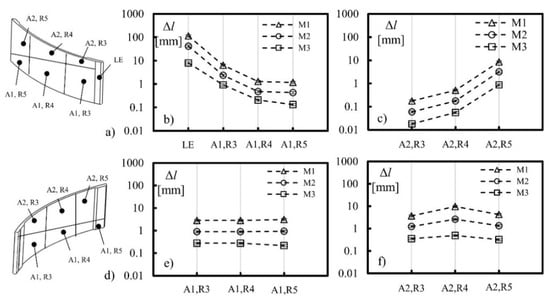
Figure 6.
Rotor wear: (a) coordinates of the patches on the pressure side and material loss, (b) on the axial section A1 and (c) on the axial section A2; (d) coordinates of the patches on the suction side and material loss, (e) on the axial section A1 and (f) on the axial section A2. R3, R4 and R5 are the radial annular areas, LE is the leading edge.
4.3. Volute
The results of the volute wear are reported in Figure 7 for the front side (Figure 7b), back side (Figure 7c), lateral side (Figure 7d), and cut-off (Figure 7e). The wear severity on the stationary parts is lower than that on the rotating part. This is mainly due to the lower particle impact number and impact velocity in these zones. The front side, back side, and lateral side have similar values of thickness reduction after 8000 h of operation. The cut-off is the most critical part of the volute: the wear severity increases over the axial direction. The maximum thickness reduction is found in the axial sector in front of the impeller outlet section, reaching a thickness reduction of 3 mm after 8000 h of operation over a cut-off radius of 175 mm.
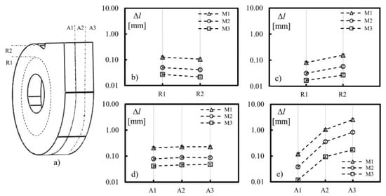
Figure 7.
Volute wear: (a) coordinates of the patches on volute and material loss, (b) on the front side, (c) back side, (d) lateral side, and (e) cut-off. R3 and R4 are the radial annular areas, A1, A2 and A3 are the axial areas.
4.4. Optimized Configuration
The combination of numerical and experimental methods made it possible to reliably assess the wear behavior of the fan operating with dust-laden flows. The results of the present work are reported in terms of thickness reduction over 8000 h of operation; the usability of such information has a key role in the estimation of the maintenance operation intervals along with the operative life of the machine. Customer warranty is, in fact, a serious concern for heavy-duty fan manufacturers, and its proper assessment could represent a substantial competitive advantage in the field of heavy-duty machine supply. Another critical role is the reduction of costs without affecting the reliability and durability of the machine. The coverage of all of the machine parts with the plate material with the highest wear resistance, without considering its price, will undoubtedly ensure the highest possible durability. However, this strategy will automatically push the machine out of the market. Intending to reach a compromise between costs and durability, the results presented previously were analyzed to identify an optimal configuration of the plate positioning. A thickness reduction of 3 mm over 8000 h of operation is set as an acceptable limit for the wear on the fan parts. This limit value was chosen by considering that the hard-facing material of the plates has a thickness of 5 mm. According to this choice, after 8000 h of operation, inspections should be carried out to assess the overall condition of the machine.
The optimized configuration for the impeller is presented in Figure 8 for the shroud (Figure 8b), the hub (Figure 8c), the pressure side (Figure 8d), and the suction side (Figure 8e). The plate materials have been positioned by combining their costs, their wear resistance, and the wear severity in the specific zone of the impeller. It can be noted that the material with the highest wear resistance (M3) is positioned only in the zones where the erosion severity does not allow the use of the cheapest materials (M1 and M2). Such zones are the leading edge (LE), a portion of the pressure side near the trailing edge (A2, R5), and a portion of the shroud corresponding to the trailing edge (TE). Similarly, M2 is employed in the center of the disc (R1), in the first radial sector of the shroud (R3), and the first radial sector of the pressure side (A1, R3). The remaining parts of the impeller were covered with M1. Looking at the stationary part, the low wear severity on the volute leads to the logical choice of using the material M1 for the front side, backside, and lateral side coverage. However, the high wear on the cut-off requires the positioning of the M2 material only in this zone. Even though such a solution can theoretically minimize the costs related to particle wear without compromising fan durability, it has to be highlighted that its implementation could be impractical due to compatibility issues that may arise when different hard-facing plates are welded together. However, the approach reported in the present work can be adapted to practical applications for only the coverage of the zones most affected by particle wear.
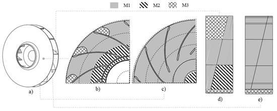
Figure 8.
Optimized configuration of the wear-resistant plates on the rotor: (a) view of the rotor, (b) shroud, (c) hub, (d) blade pressure side and (e) blade suction side.
5. Conclusions
The present work is devoted to assessing the wear severity on the internal parts of a heavy-duty centrifugal fan and optimizing the positioning of the wear-resistant plates along the flow path of the machine.
First, experimental tests were carried out to assess the wear resistance of the hard-facing plates against the dust processed by the fan. Next, a literature erosion model was used to interpolate the experimental results to obtain mathematical relations capable of predicting the wear magnitude under general impact conditions. Then, a multiphase fluid dynamic simulation of the fan was carried out to assess the particle impacts on the rotating and stationary parts. Finally, implementing the erosion model, fed with experimental coefficients, led to estimating the wear severity on each fan zone.
The rotating parts are affected by a higher level of wear than the stationary parts, and the leading edge is the zone affected by the highest amount of material loss. In addition, the three hard-facing alloys show significant differences in erosion resistance due to their different properties and chemical composition. The numerical results allowed the implementation of an optimized wear-resistant plate positioning strategy, pursuing cost reduction and increased fan durability.
Author Contributions
Conceptualization, P.S., M.P., A.V. and A.S.; methodology, N.A., N.C., M.P., A.S. and A.V.; formal analysis, N.A., N.C., A.S. and A.V.; investigation, N.A., A.S. and A.V.; resources, P.S. and O.M.; data curation, A.V.; writing—original draft preparation, A.V.; writing—review and editing, N.A., N.C., M.P., A.S., A.V. and P.S.; visualization, A.V. and M.P.; supervision, M.P. and P.S.; project administration, P.S.; funding acquisition, M.P. All authors have read and agreed to the published version of the manuscript.
Funding
This research was funded through a technological transfer grant by BOLDROCCHI GROUP Srl. Grant Number: 1.
Institutional Review Board Statement
Not applicable.
Informed Consent Statement
Not applicable.
Data Availability Statement
Not applicable.
Acknowledgments
The authors acknowledge the contribution of Nicola Zanini, Stefano Oliani and Ettore Fadiga for the support during the experimental campaign.
Conflicts of Interest
The authors declare no conflict of interest.
References
- Glasser, A.D.; Petlevich, W.J.; Sverdrup, E.F. Nature and Costs of Fan Erosion in Coal-Fired Electric Power Plants (No. EPRI-CS-1596); Westinghouse Electric Corp.: Pittsburgh, PA, USA, 1980. [Google Scholar]
- Cardillo, L.; Corsini, A.; Delibra, G.; Rispoli, F.; Sheard, A.G.; Venturini, P. Simulation of particle-laden flows in a large centrifugal fan for erosion prediction. In Turbo Expo: Power for Land, Sea, and Air; American Society of Mechanical Engineers: New York, NY, USA, 2014; Volume 45578, p. V01AT10A014. [Google Scholar]
- Castorrini, A.; Venturini, P.; Corsini, A.; Rispoli, F. Numerical simulation of the blade aging process in an induced draft fan due to long time exposition to fly ash particles. J. Eng. Gas Turbines Power 2019, 141, 011025. [Google Scholar] [CrossRef]
- Fritsche, M.; Epple, P.; Steber, M.; Rubwurm, H.J. Erosion optimized radial fan impellers and volutes for particle flows. In ASME International Mechanical Engineering Congress and Exposition; American Society of Mechanical Engineers: New York, NY, USA, 2017; Volume 7. [Google Scholar]
- Aldi, N.; Casari, N.; Pinelli, M.; Suman, A.; Vulpio, A.; Saccenti, P. Performance Modification of an Erosion-Damaged Large-Sized Centrifugal Fan. In Turbo Expo: Power for Land, Sea, and Air; American Society of Mechanical Engineers: New York, NY, USA, 2021; Volume 84898, p. V001T10A011. [Google Scholar]
- Fortini, A.; Suman, A.; Vulpio, A.; Merlin, M.; Pinelli, M. Microstructural and erosive wear characteristics of a high chromium cast iron. Coatings 2021, 11, 490. [Google Scholar] [CrossRef]
- Fortini, A.; Suman, A.; Zanini, N.; Cruciani, G. Erosive Wear Behavior of High-Chromium Cast Iron: Combined Effect of Erodent Powders and Destabilization Heat Treatments. Coatings 2022, 12, 1218. [Google Scholar] [CrossRef]
- Finnie, I.; McFadden, D.H. On the velocity dependence of the erosion of ductile metals by solid particles at low angles of incidence. Wear 1978, 48, 181–190. [Google Scholar] [CrossRef]
- EN 10269; Steels and Nickel Alloys for Fasteners with Specified Elevated and/or Low Temperature Properties. European Committee for Standardization: Brussels, Belgium, 2013.
- ASTM G76-04; Standard Test Method for Conducting Erosion Tests by Solid Particle Impingement Using Gas Jets. ASTM International: West Conshohocken, PA, USA, 2004.
- Schrade, M.; Staudacher, S.; Voigt, M. Experimental and numerical investigation of erosive change of shape for high-pressure compressors. In Turbo Expo: Power for Land, Sea, and Air; American Society of Mechanical Engineers: New York, NY, USA, 2015; Volume 56628, p. V001T01A001. [Google Scholar]
- Oka, Y.I.; Okamura, K.; Yoshida, T. Practical estimation of erosion damage caused by solid particle impact: Part 1: Effects of impact parameters on a predictive equation. Wear 2005, 259, 95–101. [Google Scholar] [CrossRef]
- Aldi, N.; Casari, N.; Pinelli, M.; Suman, A.; Vulpio, A.; Saccenti, P.; Beretta, R.; Fortini, A.; Merlin, M. Erosion behavior on a large-sized centrifugal fan. In Proceedings of the 13th European Turbomachinery Conference on Turbomachinery Fluid Dynamics and Thermodynamics, Lausanne, Switzerland, 8–12 April 2019; pp. 1–8. [Google Scholar]
- Young, J.; Leeming, A. A Theory of Particle Deposition in Turbulent Pipe Flow. J. Fluid. Mech. 1997, 340, 129–159. [Google Scholar] [CrossRef]
Publisher’s Note: MDPI stays neutral with regard to jurisdictional claims in published maps and institutional affiliations. |
© 2022 by the authors. Licensee MDPI, Basel, Switzerland. This article is an open access article distributed under the terms and conditions of the Creative Commons Attribution (CC BY-NC-ND) license (https://creativecommons.org/licenses/by-nc-nd/4.0/).