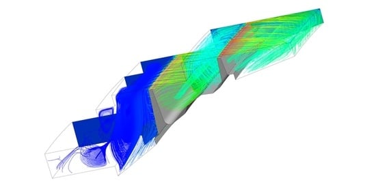
Article

Dimensionless Numbers Relationships for Outer Air Seal of Low Pressure Turbine †

by
Kacper Pałkus
1,2,* and
Piotr Strzelczyk
1
1
The Faculty of Mechanical Engineering and Aeronautics, Rzeszow University of Technology, al. Powstańców Warszawy 8, 35-959 Rzeszów, Poland
2
Doctoral School of Engineering and Technical Sciences, Rzeszow University of Technology, 35-959 Rzeszów, Poland
*
Author to whom correspondence should be addressed.
This paper is an extended version of our paper published In Proceedings of the European Turbomachinery Conference ETC14, Gdansk, Poland, 12–16 April 2021.
Int. J. Turbomach. Propuls. Power 2021, 6(3), 33; https://doi.org/10.3390/ijtpp6030033
Submission received: 28 May 2021 / Revised: 16 August 2021 / Accepted: 19 August 2021 / Published: 24 August 2021

Abstract

:
The dimensional analysis and the numerical parametric study of the typical outer air seal from a low-pressure turbine were performed in the framework of the presented paper. The most crucial variables for the flow through the outer air seal were identified and further dimensionless numbers were derived. The dependent quantities resulting from the analysis were: the axial Reynolds number (formulated with the bulk velocity, corresponding to the mass flow through the seal), the outlet swirl ratio (incorporating the exit flow angle, important for mixing) and the windage heating (related to the internal losses). Additionally, the discharge coefficient was cross-checked enabling further comparison with the available literature. The comprehensive numerical parametric study included all important contributors for the flow through the seal with a parameter operating range appropriate for engine outer air seals.

Graphical Abstract

1. Introduction

Recent advances in the Low-Pressure Turbines (LPT), dealing with super-critical profiles, ultra-thin trailing edges, and ultra-high lift blade shapes, to name a few, lead to the borders of maximal efficiency of these machines. However, there are still several areas that need further development because of their efficiency potential margin. One such field is the Outer Air Seals (OAS). In LPT, the most frequently applied concept is the labyrinth seal combined with abradables such as honeycombs. Labyrinth seals are already a very well-known solution—effective and reliable. Thus, they are the perfect choice for aircraft engines.
The majority of the labyrinth seals research was carried out for Inner Air Seals (IAS). Both kinds of seals operate under very different conditions. Since OAS are located at the outer diameter, they work at a much bigger radius than IAS. Due to that, there are locally very high circumferential Mach numbers. Moreover, at the outer diameter, configurations with two or three fins are typically applied. This is due to the fact that every additional mass at such a radius is unfavorable for the stresses of the rotating blade. Furthermore, the relative movements of the sealing parts are incomparably bigger at OAS, so that it is extremely demanding to maintain relatively small clearances between rotating and nonrotating parts. Last, but not least, OAS experience much less cooling and thus they operate at much higher temperatures, a limiting factor for many practical solutions.

1.1. Previous Work

For the previously mentioned reasons, the IAS regions were the first to attract the interest of many research groups attempting to optimize the device performance. There exist well-performing solutions of IAS, such as the brush seals investigated for instance by Dinc et al. [1], or the turning devices by Mahle [2].
Historically, one of the first studies of labyrinth seals is due to Wittig et al. [3], who performed systematic series of measurements on the straight-through seals. They mainly concentrated on the discharge characteristics and the friction factors for various configurations. The authors indicated that the scale has a significant impact on the seal performance. This is in agreement with the current knowledge stating that when flow phenomena “scale”, the similarity numbers must be preserved.
Waschka et al. [4], based on experimental evidence, suggested that the discharge behavior is dependent on the pressure ratio, the Reynolds, and the Taylor numbers. The other way to derive proper similarity numbers is through the application of Dimensional Analysis (DA). Denecke et al. [5] performed such an analysis for IAS and scaled engine conditions to the laboratory ones for 2D and 3D cases. The authors have further carried out a numerical parametric study to ascertain the influence of the derived parameters. To this aim, they have kept constant the discharge behavior and looked for the appropriate scaling of the windage heating and of the exit swirl. The main outcome of their Dimensional Analysis was that the ratios U / V a x ,   σ ,   K o u t are dependent on the following dimensionless parameters: c / R ,   Π ,   M u ,   R e U ,   K i n   k ,   P r ,   T u .
In another work by Denecke et al. [6], the dimensionless quantities were applied to prepare the experimental research in terms of total temperature increase due to losses and swirl development in convergent and divergent stepped labyrinth IAS. The authors also indicated that accurate measurements within such small devices are extremely difficult to complete, so that that the windage heating uncertainty was estimated to lie in the 2–30% range. Their work allowed Yan et al. [7] to carry further numerical studies of stepped IAS with and without the honeycomb. Those authors have shown a good agreement of their simulations with the experiments from Denecke et al. [6]; they further provided additional characterization of the seal windage heating and leakage flow.
A lot of correlations based on measurements were presented by Zimmermann and Wolff [8]. The researchers provided a complete study of the seal discharge characteristics as a function of the pressure ratio, the clearance size, the grooves, the fins number, the honeycomb cells size, and a few other parameters typical of straight and stepped configurations.
Recently, OAS have also been extensively investigated. Szymanski et al. [9] performed CFD simulations of these devices. They studied the effects of roughness and rotational speed on flow characteristics. The authors observed the influence of the very high rotational speeds (above 15,000 RPM) on the flow characteristics for small pressure ratios. Conversely, for low roughness at higher pressure ratios (above 1.5), they indicated a very limited impact of the rotational speed. Later on, Szymanski et al. [10] also compared two different experiments with the CFD outcomes, showing good agreements. Another very detailed numerical study about OAS with honeycomb is due to Fraczek et al. [11]. They have provided radial profiles both at the seal inlet and outlet including the honeycomb rubbing. Kluge et al. [12] have shown good agreement of the numerical predictions with the experimental data obtained on a new seal rig. The authors also indicated that the local flow parameters and vortices are not captured correctly. Wein et al. [13] compared experimental data with numerical computations checking multiple variants of different turbulence models with miscellaneous corrections to find the best setup for OAS. They have shown that general vortex structures and flow characteristics in comparison to PIV and 3D-PVT measurements are well captured. Nevertheless, the local flow behavior was still not adequately predicted.
Unsteady phenomena occurring in IAS were investigated for labyrinth seals by Gao et al. [14]. They showed that LES and URANS yield reasonably good agreement with steady-state measurements. Kluge et al. [15], for isolated OAS investigated in a novel rig, have also reported some unsteady pressure fluctuations at the outlet of the device, in a certain range of operation. Their comparison of numerical and experimental results shows that CFD models are able to capture the right frequency fluctuations modes.
In the above-mentioned publications, the CFD results for IAS and OAS are found to reflect well the general flow characteristics of labyrinth seals. The literature data show that steady simulations are able to capture the trends but misrepresent the local parameters estimate. Further, extensive studies for the local flow behavior, including LES, are already under investigation to compensate for the RANS modeling deficiencies in terms of the local flow features prediction.

1.2. Objectives of the Current Work

As mentioned in the previous section, the available literature does not frequently cover OAS. It is conjectured that due to the fairly different operating conditions characterizing IAS and OAS, the existing results and achievements may deviate in the case of OAS.
The present research facilitates comparison with other researchers’ outcomes, considering the significance of the already developed relations on Outer Air Seals.
To better understand the dependencies between the relevant quantities, localization of the key parameters which are crucial for OAS is needed, which is a simultaneous result of the application of DA.
A comprehensive parametric study of OAS, including all important contributors of the flow, with an appropriate parameters range for OAS and dependencies between similarity numbers, has not yet been carried out.
The present work contributes to deepening the understanding of several OAS issues and dependencies between the flow quantities; it further allows to find room for improvements in the performance of these devices.

2. Methodology

The present research deals with the aerodynamic investigation of OAS (see Figure 1). The investigation is divided into two parts. The first one consists of a Dimensional Analysis resulting in a set of dimensionless numbers characterizing the flow through the seal. The second part relies on a set of CFD investigations of typical stepped labyrinth OAS used in engine applications.
The aim of the research was the identification of the key factors influencing the flow through OAS and their mutual dependency. Recent studies have proven that CFD results show good agreement with experiments in terms of general flow characteristics, see e.g., [7,10]. Therefore, RANS are the proper choice for this kind of investigation. RANS directly provide averaged values of the flow quantities and, for general nondimensional relations, they are considered sufficient. Nevertheless, for several cases, URANS were also performed.
The most important quantitates used for the study (DA) are shown in Figure 1. These quantities were assumed to mainly contribute to the characteristics of the flow through the seal. The control stations where the flow quantities were mass averaged are also marked in Figure 1.

2.1. Dimensional Analysis

The DA allowed the identification of the key parameters controlling the flow in OAS and their reduction to dimensionless numbers. The DA is based on a mathematically proven theorem by Buckingham. It leads to the proper formulation of the similarity numbers and further to the similarity laws. As described by Qing-Ming [17], the DA method at first requires the appropriate selection of the fundamental quantities which drive the physical phenomenon. It is the most crucial step in a properly carried DA. While reviewing a physical problem, one shall consider the quantities which essentially influence the phenomenon. Following this concept, in the presented study, the variables most influencing the OAS characteristics were first found. The list of quantities relevant for the flow through OAS is given in Table 1.
A choice was made about the dependent and independent variables. This was determined by analyzing the crucial OAS aspects for LPT. Subsequently, on the basis of the DA theorem, the relations between these variables were determined. When too many quantities are prescribed they are reduced by the chosen measurement system and the redundancy is removed. The natural outcome of the procedure is a set of dimensionless numbers. It is also worth mentioning that the final form of the similarity numbers is conditioned by the choice of the fundamental unit system. In the present study, the most appropriate nondimensional numbers from the authors’ perspective are given in Equation (1). For OAS, they are: the axial Reynolds number R e a x (representing the mass flow behavior), the outlet swirl ratio K o u t (corresponding to the exit flow angle, important for mixing problems), and the windage heating σ (related to the internal losses). The dimensionless relations in general form are:
R e a x , K o u t , σ = f ( c R , Π , K i n , M u ,   k ,   p t , i n N μ )
More details on the performed dimensional analysis are given in Appendix A.
In the present study, the quantities on the right-hand side were varied and their influence on R e a x , K o u t , σ was checked. The relative clearance c / R was varied by the gap change at both fins. The geometrical features other than c / R were not varied, as this would generate too many configurations. Such geometrical dependencies were already thoroughly studied by Zimmermann and Wolf [8]. The other geometrical details of the investigated seal configuration having an impact on the seal performance are given in Appendix B. The Pressure Ratio Π was adjusted by varying the static pressure at the outlet. The inlet swirl ratio was prescribed through the velocity angle at the inlet. The circumferential Mach number M u has been calculated at the OAS inlet for the prescribed rotational speed. The ratio of the specific heats resulted from the assumed temperature corresponding to the engine conditions. The ratio p t , i n / N μ was varied by changing independently the rotational speed and the total pressure at the inlet.
Another commonly used quantity for air seals is the so-called discharge coefficient defined as:
C d = m ˙ m ˙ i d ,             m ˙ i d = p t , i n · A · f ( Π ) T t , i n ,         f ( Π ) = ( 1 Π ) 1 k   · 2 k R i ( k 1 ) [ 1 ( 1 Π ) k 1 k ]      
This coefficient is not an outcome of the DA. It rather refers to the velocity in an ideal nozzle according to the Saint-Venant–Wenzel formula. Denecke et al. [5] state that it incorporates much more information than just the mass flow, as it also embodies losses and flow characteristics for a specific geometry. This parameter is widely used in the engineering practice in many secondary airflow systems. Knowing the proper C d value and the basic flow variables, with the help of Equation (2) it is possible to calculate the mass flow through gaps, orifices, wyes, connectors, or any other system. Unfortunately, C d depends upon many parameters. Thus, it is not easy to predict its correct value. In the present research, C d will serve only as a comparison with the available literature, rather than as an outcome of the study. Here, the OAS flow characteristics are considered to be sufficiently well described by the numbers resulting from the DA. With this approach, the factors influencing particular flow phenomena can be separated.

2.2. Numerical Setup

2.2.1. Geometry

To study the influence of the nondimensional numbers on the behavior of the general OAS flow characteristics, a series of CFD analyses were performed employing the ANSYS Workbench package.
The study was performed on a model OAS typically used in the first stage of the LPT of the Energy Efficient Engine [16]. An overview of the studied configuration is given in Figure 1. The geometry is typical of LPTs. It is an OAS cavity volume of shrouded turbine blades with two fins positioned at a considerable average radius (R = 0.538 [m]), forming, together with the honeycomb, a stepped labyrinth. For simplicity reasons, a honeycomb itself was not modeled. The influence of the honeycomb can be superimposed a-posteriori to the general behavior of the seal, as confirmed by [7,8]. The minor, irrelevant features in the OAS geometry were simplified, according to standard good practices commonly followed in CFD, to avoid potential problems and numerical errors with improper grids.

2.2.2. Mesh

The model spans a 6° sector of the outer cavity in the tangential direction (according to the engine data, [16]), and it was meshed in ICEM CFD with hexahedral structured elements. A few variants of the mesh were checked. First, following [10], the analyses with y + 1 (approx. 3M cells) were prepared. Subsequently, the mesh was coarsened for the application of standard Wall Functions, resulting in y + 30 ÷ 50 (about 300 K cells, see Figure 2). The coarse mesh quality statistics were still satisfying. Table 2 shows the influence of the spatial discretization on the parameters of interest in the presented study. For this crosscheck, three grids were built. Two with y + 1 and one with coarser resolution (adopting WF) which was applied in this study.
Although there appear to be some differences in the outcomes of the different meshes in terms of the general dependencies of the characteristic parameters, in the forthcoming part of the study only the coarse grid results were considered to reduce the computational costs.

2.2.3. Boundary Conditions

The rotational periodicity was imposed on both sides of the model. The other Boundary Conditions are shown in Figure 2. At the walls, viscous flow conditions were prescribed. The rotating wall had a particular speed for each case. All walls were set to adiabatic. This assumption was considered reasonable for the general flow dependencies. The outlet was not lengthened, and use was made of the CFX functionality that automatically places a wall at each outlet section where backflow occurs. Such a solution was intended to model the flow near the outer diameter where the passing mainstream acts as a blockage for the leakage (see Figure 1). The leakage usually injects flow into the mainstream in the rear part of the cavity, and a vortex is typically created behind the second fin.
At the inlet boundary, total pressure and total temperature were set, based on the engine data. Depending on the case, the circumferential velocity angle was prescribed at the inlet, to include the pre-swirl into the simulation. The radial velocity angle at the inlet was assumed constant throughout the analyses, and equal to 45°. In engine applications, this parameter is strongly driven by the geometry. Due to the considerable extension of the OAS keep-out zones at the inlet and outlet of the device, it is impractical to influence this parameter, which is also considered to have a minor influence on the OAS operation. At the outlet boundary, a constant static pressure was imposed to keep the pressure ratio to the target value for the particular scenario. The modeled fluid was assumed compressible with a perfect gas equation of state. The specific heats and viscosity (Sutherland’s formula) were considered to be dependent on the temperature (thermally perfect gas). Throughout the analyses, a medium value of the turbulence intensity T u = 5 % was assumed at the inlet boundary. Such a value was considered to well represent the flow conditions typically occurring in OAS. The Prandtl number throughout the parametric study was set to be close to 0.7.

2.2.4. Solver

The analyses were performed using ANSYS CFX. Most of them were steady state. The SST was applied as a turbulence model as advised in [10,11,15]. The limiting convergence value was set to 1 × 10⁻⁴ (rms value), but frequently it dropped below 1 × 10⁻⁵. The simulations were carried out until all monitored parameters of interest had shown a pseudo-time constant behavior. Transient simulations were initialized from a steady solution. The numerical setup for the unsteady simulations was kept unchanged. The transient simulations were performed for several rotational speeds. The physical timestep corresponding to 1/1600 of the rotor revolution time, resulted in a maximum CFL number of about 20.

3. Results and Discussion

3.1. Axial Reynolds Number

The first dependent quantity according to Equation (1) is the axial Reynolds number R e a x , expressing the ratio of the inertia to the viscous forces. Thus, applied to OAS, R e a x incorporates information about the mass flow behavior, since it can be conveniently defined as follows:
R e a x = ρ V a x c μ = ρ V a x c R 2 π μ R 2 π = m ˙ 2 π R μ
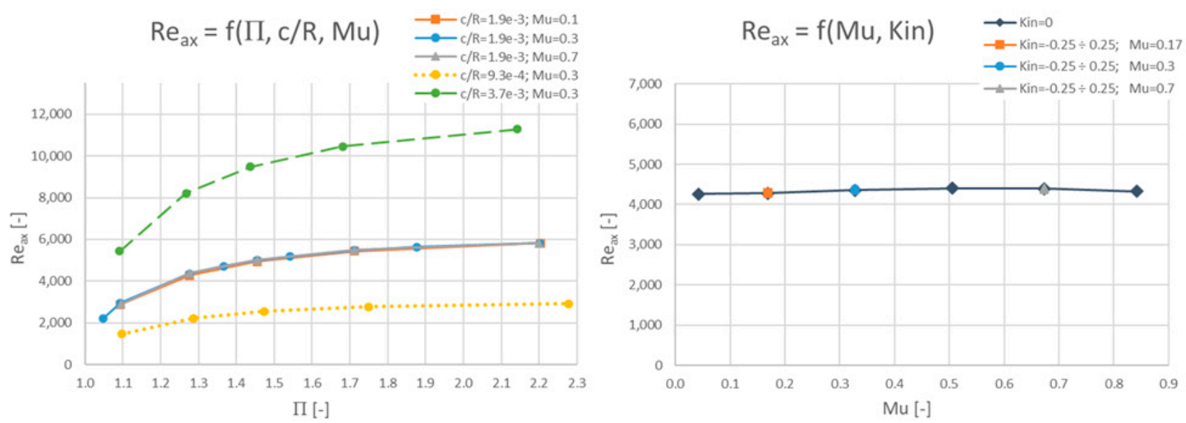
The outcomes from the numerical study on the axial Reynolds number are presented in Figure 3. From Equation (3), it is clear that, the bigger leakage mass flow through the OAS, the bigger the R e a x . The data show that the Reynolds number strongly depends on the pressure ratio Π and the relative clearance c / R . At the higher pressure ratios (approx. 1.7), the changes in the Reynolds number and, correspondingly, in the mass flow are smaller. This is due to the chocking occurring at the fins. It is also seen that for higher pressure ratios the growth rate in the R e a x weakens. Current aircraft LPT operate at considerably higher OAS pressure ratios ( 1.5 ÷ 1.7 ) then twenty years ago ( 1.3 ) . For this reason, OAS regions are even more important for nowadays engines because about 20–30% more leakage mass flow goes through the seals. Another parameter that drastically influences the axial Reynolds number is the clearance size, or in terms of nondimensional quantities, the relative clearance. It is obvious that with the increasing cross-sectional area, the mass flow and the corresponding R e a x will be higher. The present results and the dependencies of R e a x upon Π and c / R are in agreement with [7,10].
Figure 3 also shows that the Reynolds number is independent of the circumferential Mach number, thereby also from the rotational speed. Furthermore, a different inlet swirl has no influence on the R e a x (and consequently on the leakage mass flow). In conclusion, for the wide range of variables considered herein, the OAS leakage mass flow is generally independent of the rotation and the inlet velocity angle. Denecke et al. [5] stated that the mass flow is independent of rotational effects as long as the ratio U / V a x stays below 1. This is usually the case for IAS. From the outcomes of the presented study, for the practical cases of OAS, it is clear that the rotation and inlet velocity angle do not influence the mass flow even when the U / V a x ratio spans the 0.02 ÷ 2.4 range, corresponding to the M u range shown in Figure 3.
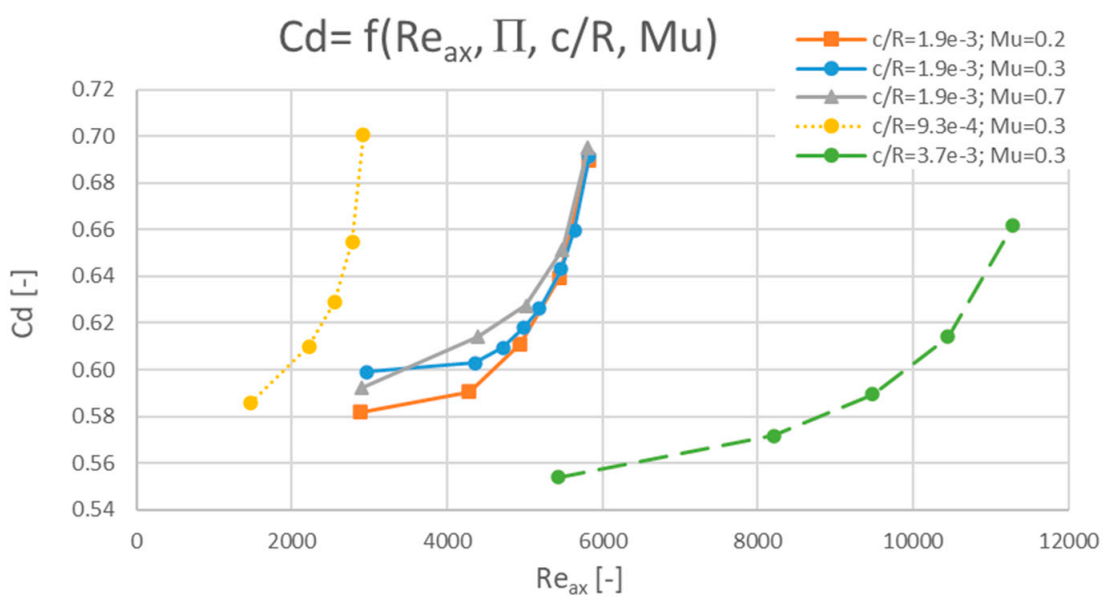
In addition, few other researchers point to independence from rotation. Zimmermann et al. [8] and Szymanski et al. [4] state that the influence of the rotation on the characteristics of the discharge coefficient C d can be neglected when R e a x > 10 , 000 . These rotation effects become significant with decreasing Reynolds number, because the pressure losses increase, due to the growing friction losses. Figure 4 presents C d plotted against R e a x with varying relative clearance, pressure ratio, and circumferential Mach number to facilitate the comparison with the available literature. The above-mentioned small dependency of C d on the rotation rate is clearly visible in Figure 4, already near R e a x 6000 .
Despite the generally good agreement with the literature results of the rotational effects with respect to the relative clearance, two different trends are found in the available research reports. Wittig et al. [3] and Waschka et al. [4] demonstrated that for the straight labyrinth seal with various fins configurations, C d decreases with a clearance reduction. Conversely, in the current study and similarly to Willenborg et al. [18], Schramm et al. [19], and Zimmermann and Wolff [8] in stepped labyrinths cases, C d has been found to decrease with increasing clearance. Moreover, Szymanski et al. [10], comparing two experiments with CFD, also observed two different unexplained trends of C d with respect to the clearance in both analyzed experiments.
The first and most basic difference between the mentioned cases is the seal configuration—straight or stepped. In the case of straight-through seals (still commonly applied at cylindrical parts of the engines), the bigger the gap, the bigger the C d . Whereas for stepped ones, the bigger the gap, the smaller the C d . Thus, for different types of geometries, there is a completely reverse discharge behavior. Similar conclusions were also drawn by Denecke et al. [20] who studied straight, forward, and backward stepped configurations with and without rub-grooves. They indicated that the outcomes valid for the stepped seals should not be put together with those of the straight seal type. Furthermore, the differences in the geometry result in a modified flow guidance and a visibly altered discharge behavior. In the case of the straight-through geometry, the leakage directly enters the downstream seal chamber, and it reduces the sealing. The step in the configuration serves as an additional stagnation point and redirects the jet towards the bottom of the seal improving the sealing.
All these findings show that accurate correlations and dependencies for the discharge coefficient are difficult to determine. Both R e a x and C d provide some information about the leakage mass flow. While the Reynolds quantifies the ratio of the inertia to viscous forces, the discharge coefficient C d compares the true mass flow to the ideal value as a result of the miscellaneous losses. It is also possible that the C d studied by other researchers was influenced by different geometric features such as the distance between the fins, the radii of the fins, and their shapes. That could have an impact on the results. Already, Zimmermann and Wolff [8] stated that the generalized correlation of C d cannot be very accurate. This is also addressed in the presented paper, because C d depends on very many variables. Nevertheless, the C d parameter is eagerly used, due to its convenient use in engineering applications as discussed in the previous section.

3.2. Leakage Exit Swirl Ratio

The dimensionless expression for the inclination of the flow velocity vector, resulting from the performed DA, is the swirl ratio K . This parameter indicates how big is the circumferential velocity of the flow with respect to the circumferential velocity of the rotor. In the case of OAS, the velocity of the blade tip reaches significant numbers, due to the high rotational speeds and the considerable radii. The outlet swirl is thus a very big contributor to the mixing of the OAS leakage and of the mainstream flow in LPT.
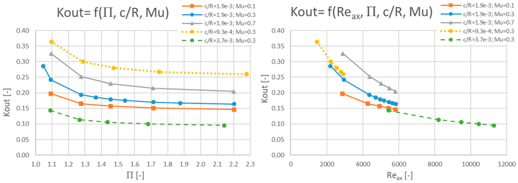
When it comes to the exit swirl ratio, parametrized with the rotational speed and the clearance decrease, the dependency on the pressure ratio is marginally higher. However, it can be assumed that even for high speeds and very small clearances, beginning with a certain value of the pressure ratio (approximately 1.4 ), the swirl ratio is independent from Π (see Figure 5). Such a behavior is present for different relative clearances and circumferential Mach numbers.
From Figure 5 it can be concluded that with a relative clearance increase and a M u decrease, the swirl ratio at the outlet of the cavity tends towards 0, that is the flow tends to be unturned. This is because the bigger the gap at the fins and the smaller the revolutions, the more flow crosses the OAS without undergoing any particular effect. Such a behavior, compared to the small relative clearances, indicates that the flow is especially strongly turned at the fins themselves. For smaller clearances, the shear layer dominates in the smallest cross-sectional area (at fins). In other words, very little flow is free from the boundary layer influence. The leakage is subjected then to viscous effects. Since the rotor is turning, the flow due to viscosity effects is also turned. The same conclusion is achieved in terms of the meaning of the Reynolds number, expressing the ratio of the inertia to the viscous forces. For small Reynolds, viscous forces are dominating, which is visible for small gaps in Figure 5. This is reflected in the higher swirl ratio at the outlet.
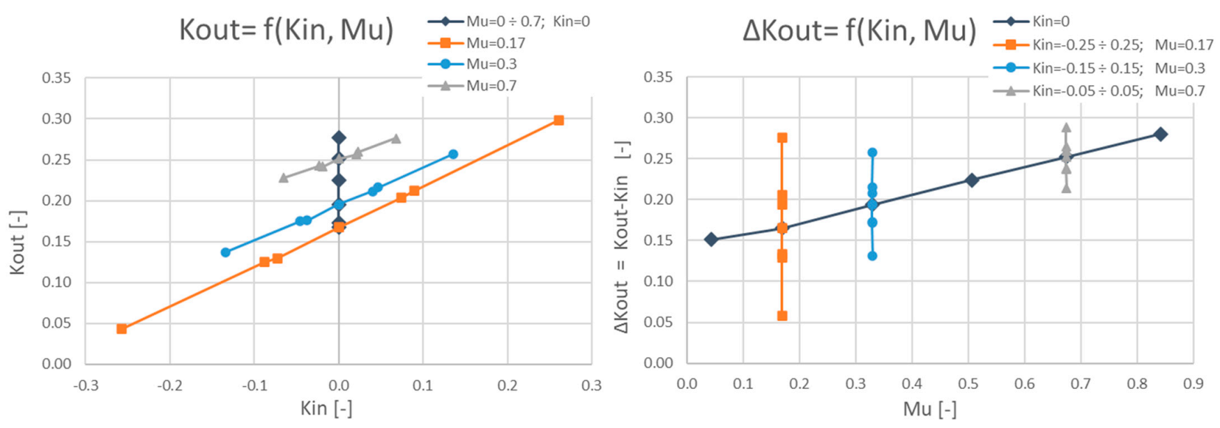
Figure 6 shows that the outlet swirl ratio is strongly dependent especially on two parameters: the circumferential Mach number of the rotor M u and the level of the swirl ratio at the inlet K i n . The inlet swirl corresponds to the initial inclination of the leakage velocity vector entering the cavity. It is obvious that when the swirl at the entrance of the cavity is higher, in the same manner, the outlet swirl will be higher. This is well visible from the curves presented in Figure 6, highlighting that the outlet swirl ratio linearly depends on the inlet pre-swirl. The slope of the lines for different M u is almost the same; only the level changes. This slope remains also unchanged when the velocity vector is directed against the rotational speed. It additionally confirms that both numbers M u and K i n resulting from the DA describe separate phenomena. Figure 6 also shows that a M u increase results in a linear increase of the outlet swirl ratio. The induced, additional turning at OAS is in the direction of the rotation. It is partly an effect of the flow turning at the rotating walls due to the viscosity of the fluid and partly to the interaction with the mid-chamber vortices. The results agree well with those reported in [5].

3.3. Windage Heating

Windage heating corresponds to the outlet temperature rise and is a measure of the power losses due to vortices, friction, etc. The outlet temperature increase comes from the work input by the rotating blade through viscous forces. In the present study, due to the assumption of adiabatic walls, the heat transfer associated with the effects of the cooling at the walls (normally present in the experiments) cannot be accounted for. Figure 7, providing windage heating dependency on the pressure ratio Π , indicates that σ shows very similar trends to K o u t . With increasing Π and c / R , windage losses tend to drop.
The smaller the leakage (smaller Reynolds number), the bigger the relative contribution of the viscous forces. Thus, the lesser flow in the axial direction (either due to the tight gaps or due to small pressure difference), the bigger the contribution of the circumferential stresses. Then, the more enhanced mixing due to the relatively bigger contribution of the viscous forces on the circumferential direction and the more increased windage heating. Much in the same way as for the exit swirl ratio, at higher pressure rations (approx. 1.4), σ is almost independent from Π . This leads to the conclusion that both quantities σ and K o u t should have similar trends. This is confirmed by the results presented in Figure 7, however, only when the inlet swirl does not vary. To compare cases with different pre-swirl levels, a difference operator (delta) between outlet and inlet swirl values is applied (see Figure 7, right panel). The right panel shows that the drivers for both σ and K o u t are identical with respect to the relative clearance, the pressure ratio, and the circumferential Mach number, that is to say, the trends of σ and K o u t are linear with respect to the changes in the mentioned parameters. However, the influence of the pre-swirl ratio is different, as shown by the decreasing slopes contrary to the increasing ones in the case of K o u t .
Figure 8 presents the influence of the circumferential Mach number and of the inlet swirl ratio on σ . Clearly, the increase in M u leads to a linear increase in the windage losses. With the higher speed of the rotor, the vortices generated by the enhanced circumferential component become stronger, yielding more windage losses. This was also shown in [5,7].
A reverse trend is visible in the second chart of Figure 8. A negative value of K i n indicates that the velocity vector points against the direction of rotation. The data clearly show that if velocity is inclined towards the rotation direction, the windage losses becomes smaller. On the other hand, if the velocity acts against the rotation, a larger interaction of the leakage with the vortices (induced by the rotation) will occur, leading to more losses. This contributes to the different trends between windage heating and exit swirl ratio.

3.4. Other Parameters Resulting from Dimensional Analysis

There are two other dimensionless numbers stemming from the performed DA: p t , i n / N μ and k . The ratio of specific heats k is considered to have a minor influence on R e a x ,   K o u t and σ . Additionally, it is impossible to influence this parameter during the design, because it is one of the characteristics of the fluid itself for a given case. Conversely, the ratio p t , i n / N μ can vary with respect to the inlet total pressure and the rotational speed. The effects of variations in this quantity on the dependent variables resulting from the DA is presented in Figure 9. For all below cases, the pressure ratio was kept at the same level.
Firstly, the impact of the ratio p t , i n / N μ on the R e a x is affected by other groups. It was already shown that the axial Reynolds does not vary with M u . On the other hand, it is obvious that an increase of the inlet pressure, that is of the density, will also lead to a proportional increase of the mass flow. This effect needs to be accounted for when evaluating the Reynolds number.
However, with respect to the other parameters, K o u t and σ , the ratio p t , i n / N μ exhibits almost the same trends, regardless of the p t , i n or M u variations. Both charts also show that the above-mentioned trends tend to show asymptotic behavior for large values of the p t i n / N μ ratio, and have steep gradients for smaller ones. The high gradients refer to the situation when the inlet total pressure is small and the rotation big. It leads to the conclusion that the bigger the total pressure (the bigger the leakage), the smaller the additional outlet swirl ratio and the windage losses. Since in LPT the total pressure decreases strongly along the machine, the downstream stations will experience higher turning of the leakages, higher windage losses, and correspondingly smaller leakages.

3.5. Unsteady Effects at OAS in Dimensionless Numbers

It has already been mentioned that RANS calculations provide time-averaged values of the flow quantities, and for general nondimensional relations they are sufficiently accurate. Nevertheless, for several cases with different rotational speeds, a set of URANS calculations was also performed to investigate the influence of the vortices’ unsteadiness on the dimensionless numbers. The differences between the steady and transient cases are shown in Table 3.
The unsteady simulations have shown minor variations in the nondimensional parameters resulting from the DA. The largest percentage difference yields a −1.1% value for the outlet swirl ratio. The vortices in the OAS configuration presently investigated do not show noticeable unsteady effects. RANS are still considered to representatively capture the trends of the nondimensional numbers. Nevertheless, some other additional effects could appear if the influence from the mainstream flow was considered.

4. Conclusions

The Dimensional Analysis and a numerical parametric study of an OAS were performed in the framework of the present paper. The most crucial variables were identified and further nondimensional numbers were derived. To investigate the influence of the parameters, a few CFD models of the typical LPT OAS were built. The general dependencies between the nondimensional quantities were found to be well modelled by RANS, offering a comprehensive overview of the OAS characteristics.
The Reynolds number has been found to be independent of the rotational speed and pre-swirl effects, and strongly depended on the relative clearance, pressure ratio, and p t , i n / N μ ratio.
Both the outlet swirl ratio and the windage heating, have shown the same trends, suggesting that they are driven by similar phenomena. The only different behavior was found with respect to the inlet swirl ratio. Both parameters appeared to be almost independent of the pressure ratio.
Additionally, the discharge coefficient relations were cross-checked to offer a ground for comparison with the available literature data. It was found that C d is essentially driven by multiple parameters. In the first place, it is chiefly influenced by the geometry: c / R ratio, seal configuration (number of stagnation points, steps), and pressure ratio Π . Of some importance are also M u , K i n , p t , i n / N μ , and k . The obtained results are in good agreement with the literature data. All findings show that accurate correlations and dependencies for the discharge coefficient are difficult to determine in a quantitative manner.
For the presently investigated OAS, and with reference to the parameters operating range corresponding to nowadays LPT conditions, the following dependencies were found:
R e a x = f ( c / R , Π ,   p t , i n N μ )
K o u t = f ( c / R , M u , p t , i n N μ , K i n ) = f ( R e a x ,   M u ,   K i n )
σ = f ( c / R , M u , p t , i n N μ , K i n ) = f ( Δ K o u t , K i n )
To facilitate the comparison of specific phenomena and prediction of OAS behavior, proper dimensionless numbers should be retained. With respect to the mass flow behavior, the axial Reynolds R e a x turns out to be the most important. The outlet swirl ratio K o u t is crucial for mixing, while the windage heating σ controls the internal losses.

Author Contributions

Conceptualization, K.P. and P.S.; methodology, K.P. and P.S.; software, K.P.; validation, K.P. and P.S.; formal analysis, K.P.; investigation, K.P.; resources, K.P.; data curation, K.P.; writing—original draft preparation, K.P.; writing—review and editing, K.P. and P.S.; visualization, K.P.; supervision, P.S.; project administration, K.P. All authors have read and agreed to the published version of the manuscript.

Funding

This research received no external funding.

Data Availability Statement

The data presented in this study are available on request from the corresponding author.

Conflicts of Interest

The authors declare no conflict of interest.

Abbreviations

The following symbols and abbreviations are used in this manuscript:
a Local speed of sound
b ,   b i any dimensional quantity c Clearance size
c p Specific heat capacity
c R Relative clearance
k Ratio of specific heats
m ˙ Leakage mass flow
p Pressure
A Cross-sectional area at fin
C d Discharge coefficient
K = V θ N R Swirl ratio
M u = U k R i T i n Circumferential Mach number
N Rotational speed
PrPrandtl number
R Average radius of fins
R i Individual gas constant
R e a x = ρ V a x c μ = m ˙ 2 π R μ Axial Reynolds number
T Temperature
TuTurbulence intensity
U =   π N 30 R Rotor fins circumferential velocity
V a x Axial velocity component
V r Radial velocity component
V θ Circumferential velocity component
α ,   β ,   δ any exponents
μ Viscosity
ρ Density
Π = p t , i n / p o u t Pressure Ratio
Ψ ,   Ψ i any dimensionless quantity σ = 2 c p ( T t , o u t T t , i n ) U 2 Windage heating
Subscripts:
t Total quantities
in, out Inlet, Outlet
Acronyms:
CFD Computational Fluid Dynamics
DADimensional Analysis
IAS/OASInner/Outer Air Seal
LESLarge Eddy Simulations
LPTLow Pressure Turbine(s)
PIV Particle Image Velocimetry
PVTParticle Velocimetry Tracking
(U)RANS(Unsteady) Reynolds-Averaged Navier-Stokes

Appendix A. Main Steps of the Dimensional Analysis

The basis for the dimensional analysis is the mathematically proven Buckingham’s theorem. Qing-Ming [17] indicated that the power law formula can express the dimension of any quantity. In the method, an emphasis is placed on the careful selection of fundamental quantities in solving problems. As noted by Qing-Ming [17], it is possible, based on the theorem, to find from the regular dimensional relationship:
b = f ( b 1 ,   b 2   ,   b n ) ,
of a physical problem, where the variables in a function are independent, the dimensionless relationship between the variables. After adopting the power formula, the relation can be presented as:
Ψ = c o n s t · Ψ 1 α ,   Ψ 2 β , Ψ N k δ ,  
In addition, as indicated by Qing-Ming [17], one should only consider the numbers essential for the problem being investigated. The irrelevant independent variables should be omitted.
When attempting to the analysis of a physical phenomenon, frequently it is better to start from the relationship in dimensionless form. Then, units do not need to be converted, and also the amount of work is considerably reduced because the number of independent variables is reduced, in addition, the results are more universal.
In the presented work, the essential for the researched phenomena were variables listed in the Table 1. Additionally, the set of variables is given in the form of function in Equation (A3).
f ( c ,   R ,   N ,   a ,   R i ,   μ ,   p t , i n ,   p t , o u t ,   T t , i n ,   T t , o u t ,   m ˙ ,   V θ , i n ,   V θ , o u t , V r , i n ,   V r , o u t , V a x , i n ,   V a x , o u t ) = 0
Base units were chosen: [Time], [Length], [Mass], and [Heat], which corresponds to [s], [m], [kg], and [K], respectively.
The chosen independent variables were: R ,   N ,   μ ,   T t , i n and their units: [ m ] ,   [ s 1 ] ,   [ k g · m 1 · s 1 ] ,   [ K ] .
The dependent variables though: c ,   a ,   R i ,   p t , i n ,   p t , o u t ,   T t , o u t ,   m ˙ ,   V θ , i n ,   V θ , o u t , V r , i n ,   V r , o u t ,   V a x , i n ,   V a x , o u t . Afterwards, each parameter was evaluated in terms of independent variables. Then, based on Buckingham’s theorem and the power low, the units were compared. As an example, in the presented work, mass flow through the seal considered with respect to the chosen independent variables:
m ˙ = f ( R ,   N ,   μ ,   T t , i n ) = const · R α · N β · μ γ · T t , i n δ
consideringly on the units:
[ kg · s 1 ] = [ m ] α · [ s 1 ] β · [ k g · m 1 · s 1 ] γ · [ K ] δ
Then, one obtains:
{ [ T i m e ] : 1 = β γ [ L e n g t h ] :     0 = α γ [ M a s s ] :           1 = γ                       [ M a s s ] :           0 = δ                     { α = 1 β = 0 γ = 1 δ = 0   m ˙ = f ( R ,   μ ) const · R 1 · μ 1 1 = m ˙ R μ   R e a x
The outcome is the quantity in the dimensionless form.
Next, one should look for the other known numbers and relate them to the investigated phenomenon. In the case of mass flow through the outer air seal, the corresponding number is axial Reynolds number, Equation (A6). The resultant dimensionless numbers for the outer air seal are given in Equation (1).

Appendix B. Details of the Investigated Seal Geometry

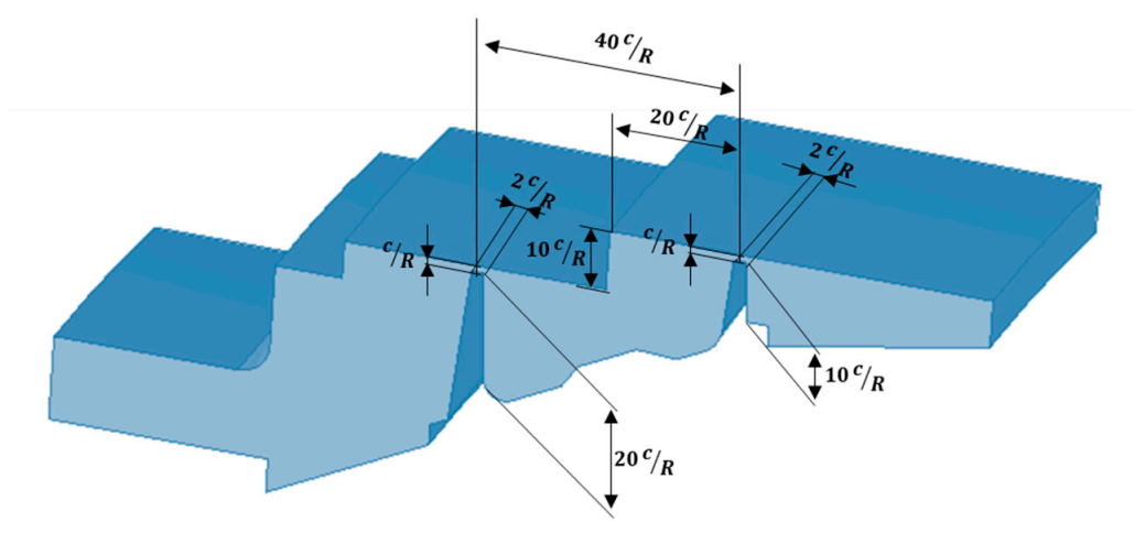
It is known from the works of other researchers, for example Zimmermann and Wolf [8], that the seal performance is influenced by the geometry itself. To provide better insight into the investigated seal, in Figure A1 and in Table A1 are given geometrical details of the configuration.
Table A1. Geometrical details of the outer air seal investigated in the study.
Clearance Size, c 0.001 [m]
Average radius of the fins, R 0.538 [m]
1st fin height 20 c R
2nd fin height 10 c R
Width of the fins 2 c R
Distance between the fins 40 c R
Step height 10 c R
Distance from the step to the 2nd fin 20 c R
Corner radii of the fins0 (sharp fins)
Figure A1. Geometrical details of the outer air seal investigated in the study.
Ijtpp 06 00033 g0a1

References

  1. Dinc, S.; Demiroglu, M.; Turnquist, N.; Mortzheim, J.; Goetze, G.; Maupin, J.; Hopkins, J.; Wolfe, C.; Florin, M. Fundamental Design Issues of Brush Seals for Industrial Applications. J. Turbomach. 2002, 124, 293–300. [Google Scholar] [CrossRef]
  2. Mahle, I. Improving the Interaction Between Leakage Flows and Main Flow in a Low Pressure Turbine. ASME J. Turbomach. 2010, 7, 1177–1186. [Google Scholar] [CrossRef]
  3. Wittig, S.L.K.; Dorr, L.; Kim, S. Scaling Effects on Leakage Losses in Labyrinth Seals. J. Eng. Power 1983, 105, 305–309. [Google Scholar] [CrossRef]
  4. Waschka, W.; Wittig, S.; Kim, S. Influence of High Rotational Speeds on the Heat Transfer and Discharge Coefficients in Labyrinth Seals. J. Turbomach. 1992, 114, 462–468. [Google Scholar] [CrossRef]
  5. Denecke, J.; Farber, J.; Dullenkopf, F.; Bauer, H.J. Dimensional Analysis and scaling of rotating seals. ASME J. Turbomach. 2005, 47268, 1149–1160. [Google Scholar] [CrossRef]
  6. Denecke, J.; Dullenkopf, K.; Wittig, S.; Bauer, H.-J. Experimental Investigation of the Total Temperature Increase and Swirl Development in Rotating Labyrinth Seals. ASME J. Turbomach. 2005, 3, 1161–1171. [Google Scholar] [CrossRef]
  7. Yan, X.; Li, J.; Song, L.; Feng, Z. Investigations on the Discharge and Total Temperature Increase Characteristics of the Labyrinth Seals with Honeycomb and Smooth Lands. J. Turbomach. 2009, 131, 041009. [Google Scholar] [CrossRef]
  8. Zimmermann, H.; Wolff, K.H. Air System Correlations: Part 1—Labyrinth Seals; ASME Paper 98-GT-206; ASME: New York, NY, USA, 1998. [Google Scholar]
  9. Szymanski, A.; Wroblewski, W.; Dykas, S. Flow Analysis of the Turbine Rotor Tip Seal on a Highly Rotary Test Rig. In Proceedings of the 11th European Conference on Turbomachinery Fluid dynamics & Thermodynamics, ETC11, Madrid, Spain, 23–27 March 2015; pp. 23–27. [Google Scholar]
  10. Szymanski, A.; Dykas, S.; Wroblewski, W.; Fraczek, D. Experimental and Numerical Validation Study of the Labyrinth Seal Configurations. In Proceedings of the 12th European Conference on Turbomachinery Fluid Dynamics & Thermodynamics ETC12, Stockholm, Sweden, 3–7 April 2017. [Google Scholar] [CrossRef] [Green Version]
  11. Fraczek, D.; Wroblewski, W.; Chmielniak, T. Influence of Honeycomb Rubbing on Tip Seal Performance of Turbine Rotor. In Proceedings of the 11th European Conference on Turbomachinery Fluid Dynamics & Thermodynamics, Madrid, Spain, 23–27 March 2015. [Google Scholar] [CrossRef]
  12. Kluge, T.; Wein, L.; Schmierer, R.; Seume, J.R. Sensitivity analysis, instrumentation and design, and experimental validation of a novel labyrinth seal rig. In Proceedings of the 13th European Conference on Turbomachinery Fluid dynamics & Thermodynamics ETC13, Lausanne, Switzerland, 8–12 April 2019. [Google Scholar] [CrossRef]
  13. Wein, L.; Kluge, T.; Seume, J.R.; Hain, R.; Fuchs, T.; Kähler, C.; Schmierer, R.; Herbst, F. Validation of RANS Turbulence Models for Labyrinth Seal Flows by Means of Particle Image Velocimetry. In Proceedings of the ASME Turbo Expo 2020: Turbomachinery Technical Conference and Exposition, London, UK, 21–25 September 2020. [Google Scholar] [CrossRef]
  14. Gao, F.; Chew, J.W.; Beard, P.; Amirante, D. Numerical Studies of Turbine Rim Sealing Flows on a Chute Seal Configuration. In Proceedings of the 12th European Conference on Turbomachinery Fluid dynamics & Thermodynamics ETC12, Stockholm, Sweden, 3–7 April 2017. [Google Scholar] [CrossRef] [Green Version]
  15. Kluge, T.; Lettmann, I.S.; Oettinger, M.; Wein, L.; Seume, J.R. Unsteady Flow Phenomena in Turbine Shroud Cavities. In Proceedings of the Global Power and Propulsion Society, Chania, Greece, 7–9 September 2020. [Google Scholar] [CrossRef]
  16. Leach, K.; Thulin, R.; Howe, D. Energy Efficient Engine. In Tubrine Indermediate Case ad Low Pressure Turbine Component Test Hardware Detailed Design Report; NASA CR-167973; PWA-5594-191; NASA Lewis Research Center: Cleveland, OH, USA, 1982; p. 44135. [Google Scholar]
  17. Qing-Ming, T. Dimensional Analysis with Case Studies in Mechanics; Springer: Berlin/Heidelberg, Germany, 2011; pp. 1–41. [Google Scholar]
  18. Willenborg, K.; Kim, S.; Wittig, S. Effects of Reynolds Number and Pressure Ratio on Leakage Loss and Heat Transfer in a Stepped Labyrinth Seal. J. Turbomach. 2001, 123, 815–822. [Google Scholar] [CrossRef]
  19. Schramm, V.; Willenborg, K.; Kim, S.; Wittig, S. Influence of a Honeycomb Facing on the Flow Through a Stepped Labyrinth Seal. J. Eng. Gas Turbines Power 2000, 124, 140–146. [Google Scholar] [CrossRef]
  20. Denecke, J.; Schramm, V.; Kim, S.; Wittig, S. Influence of Rub-Grooves on Labyrinth Seal Leakage. J. Turbomach. 2003, 125, 387–393. [Google Scholar] [CrossRef]
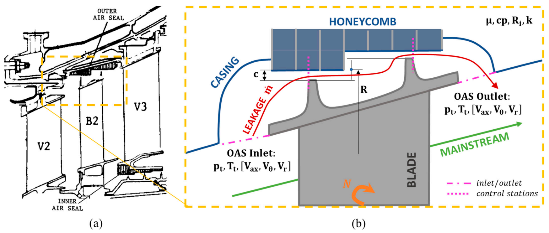
Figure 1. (a) A typical OAS of LPT [16]. (b) Meaningful quantities considered for flow through the OAS.
Ijtpp 06 00033 g001
Figure 2. OAS model, boundary conditions, and mesh.
Ijtpp 06 00033 g002
Figure 3. Dependency of axial Reynolds number on Π , c / R , M u , and K i n .
Ijtpp 06 00033 g003
Figure 4. Discharge coefficient for the researched OAS for different e a x ,   Π , c / R , and M u .
Ijtpp 06 00033 g004
Figure 5. Exit swirl ratio dependency on π , R e a x , c / R , and M u .
Ijtpp 06 00033 g005
Figure 6. Exit swirl ratio dependency on M u and K i n .
Ijtpp 06 00033 g006
Figure 7. Windage heating dependency on π , R e a x , c / R and M u and K i n .
Ijtpp 06 00033 g007
Figure 8. Windage heating against the circumferential Mach number and inlet pre-swirl ratio.
Ijtpp 06 00033 g008
Figure 9. Influence of p t i n / N μ on axial Reynolds number, outlet swirl ratio, and windage heating.
Ijtpp 06 00033 g009
Table 1. Selection of quantities applied for Dimensional Analysis of OAS.
Quantities Considered Meaningful for OAS DA c ,   R ,   N ,   a ,   R i ,   μ ,   p t , i n ,   p t , o u t ,   T t , i n ,   T t , o u t ,   m ˙ ,   V θ , i n ,   V θ , o u t , V r , i n ,   V r , o u t , V a x , i n ,   V a x , o u t
Base units[s], [m], [kg], [K]
Chosen independent variables R ,   N ,   μ ,   T t , i n [m], [s−1], [kg∙m−1∙s−1], [K]
Chosen dependent variables c ,       a ,     R i ,     p t , i n ,     p t , o u t ,     T t , o u t ,     m ˙ ,     V θ , i n ,   V θ , o u t , V r , i n ,   V r , o u t , V a x , i n ,   V a x , o u t
Table 2. Grid Convergence Index for the most important dimensionless OAS parameters.
r 21 r 32 ϵ 21 ϵ 32 p G C I 21 G C I 32
R e a x 1.3 1.4 0.005 0.034 6.0 1.8 × 10 3 2.2 × 10 3
K o u t 1.3 1.4 0.001 0.019 10.2 1.0 × 10 4 1.3 × 10 4
σ 1.3 1.4 0.011 0.047 4.2 6.6 × 10 3 7.7 × 10 3
C d 1.3 1.4 0.002 0.017 6.7 5.7 × 10 4 7.1 × 10 4
Table 3. Differences on dimensionless numbers between steady and unsteady solutions for OAS cases with c/R = 1.9 × 10⁻³; Π = 1.3 ;   K i n = 0 ; for different rotational speeds.
M u = 0.17 M u = 0.3 M u = 0.6
R e a x 0 % 0.5 % 0.3 %
K o u t 0.2 % 0.1 % 1.1 %
σ 0.4 % 0.8 % 0.9 %
C d 0.7 % 0.2 % 0.1 %
Publisher’s Note: MDPI stays neutral with regard to jurisdictional claims in published maps and institutional affiliations.