1. Introduction
The trend towards high power-density in turbomachines is directly linked to higher pressures and temperatures in the components. As a consequence, mechanical and thermal loads increase in a way that can require considerable redesign measures to ensure mechanical integrity. One of these is the introduction of component cooling. An efficient way to achieve this is through impingement cooling. Applying this approach to rotating-disk configurations, like back walls of bladed wheels or cavities, creates, from the physical point of view, an unsteady heat transfer situation, which requires large computational effort to be resolved. On the other hand, when a jet impinges on an axisymmetric wall, a time-averaged information on the temperature distribution is often sufficient for further analysis and design purposes. In this paper, a way to compute time-averaged temperatures through a steady-state CHT mixing-plane approach is presented, allowing to assess thermal loads in corresponding solids. The validity of the proposed approach is demonstrated using a centrifugal compressor stage with back wall jet impingement cooling. Validation is carried out by comparing the results of the fluid-solid mixing plane approach against full transient CFD analysis and measurement data for four different operating points.
1.1. High Pressure-Ratio Turbocharger Needs
The demand for increased turbocharger boost pressure is driven by economic and ecological aspects. The customer value is a higher power density for an increased power output and at the same time a reduced specific fuel consumption. However, this development comes with challenges in turbocharger components and, in particular, compressor design. One of those issues are the increased thermal loads of the compressor stage, with impact on possible material failure mechanisms, such as low cycle fatigue, high cycle fatigue, and creep. The consequence is the exceeding of allowed limits for prescribed wheel exchange-intervals. Changing from common compressor material to more heat resistant materials is often economically not acceptable due to considerably higher product and production costs.
1.2. Characteristics of Impingement Jet Cooling
Considering the aforementioned situation, a temperature reduction by efficient cooling is needed, if higher pressures are envisaged. One of the most effective known cooling-methods for fluid/solid interaction is impingement cooling, reaching heat transfer coefficients up to three times larger than conventional convection cooling. The basic mechanisms of impingement cooling, as well as the corresponding effects, have been extensively investigated experimentally and numerically for both single and multi-array configurations. Accordingly, there is a large body of literature present (see, for example, References [
1,
2]) and the phenomena are well understood. On the other hand, from the numerical point of view, the computation of impingement cooling still represents a challenge. The flow undergoes different states, from free shear flow in the jet over the anisotropic state in the impingement region to the thin boundary layer in the downstream part. Moreover, transition and secondary flows may play a considerable role, depending on the Reynolds number. Therefore, the numerical results are very sensitive on the chosen turbulence model [
3,
4]. Applying this method to the cooling of the compressor backwall involves additional effects, which further complicates the physical situation: the rotation will generate crossflow conditions, and if multiple jets are foreseen, complex horse-shoe vortex systems will develop, with corresponding effects on the single jets and on the shear flow along the wall.
A large number of studies on cooling mechanisms in the gas turbine components are often related to blade cooling in axial machines; for an overview, see References [
5,
6]. When moving to radial machines the range of studies reduces considerably, and for impingement cooling on rotating components there are very few publications, with very basic configurations [
7,
8,
9,
10,
11,
12,
13], often considering in an isolated way one single effect among all mentioned above. Therefore, the development of this type of cooling has been mostly performed using an experimental approach. Nevertheless, in order to better understand the flow physics and, thus, improve and optimize the device, a deeper insight, as well as a tool for parametric studies, is needed. When considering CFD as an appropriate method, the following points need to be considered, since, including impingement cooling in this particular physical situation is not straightforward:
Impingement cooling occurs in a stationary frame of reference, while the wall to be cooled is in a rotating frame of reference
Impingement cooling of a rotating wall is, therefore, an unsteady heat transfer problem
Full unsteady coupled CFD - heat transfer computations are usually too time consuming to be included as a standard tool in the design procedure due to large disparity in fluid and solid time scales.
1.3. Conjugate Heat Transfer (CHT)
Conjugate heat transfer (CHT) analysis describes the transfer of heat from a solid wall to the adjacent fluid. Considering turbomachinery applications, this concerns, e.g., the transfer of heat from the fluid in the compressor to the impeller blades, and vice versa. Applying dimensional analysis, it can be clearly seen that the time scales for the diffusion of heat in the fluid and the solid have differences of various orders of magnitude [
14]. Additionally, there is no convective transport of heat in the solid. Therefore, a full transient CHT simulation to solve the conservation equations in an unsteady manner would require computational times not affordable for everyday engineering development. Accordingly, there is a whole body of methods, and publications aimed to accelerate unsteady CHT simulations with various approaches [
14,
15,
16]. The main goal in the presented approaches is to resolve the transient behavior in the solid, for example, during engine start-up, in order to assess mechanical integrity. Therefore, even with the proposed acceleration techniques, computational times are considerably large, such as reported in Reference [
15], where a week is given as “typical” and “reasonably short time” for a simulation.
Parallel to applications where the transient behavior needs to be assessed, there is a series of situations which are inherently unsteady but for which a time averaged solution would be sufficient for the subsequent analysis of the results. This is, for example, present in cooling situations with discrete jets impinging on rotating disks. Reference [
9] gives a comprehensive overview of the problem and performs experiments to assess the time-averaged Nusselt-number over the disk radius for different radial injection locations. For design purposes the obtained Nusselt-number distribution is already sufficient. As a consequence, to support the design of efficient impingement cooling within the compressor development design-cycle, a procedure to compute the time-average effect of the cooling on the rotating disk would be sufficient. Numerical algorithms for steady state CHT coupling can be found, e.g., in Reference [
17]. This algorithm uses a weak coupling of the interface heat fluxes, i.e., the interface heat fluxes are only balanced at steady state and the solution is then advanced. Strongly coupled algorithms maintain the conservation of energy throughout the whole process by accounting for the interface heat flux through the coefficient matrix [
18]. The proposed approach uses such a tight coupling but implicitly embodies the theory of a mixed out steady state solution to overcome the need for transient simulations in the context of impingement cooling on centrifugal compressors.
2. Proposed Approach
On the fluid side, there are various approaches where the inherently unsteady rotor-stator interaction is approximated by a steady-state computation. This is necessary because unsteady computations during the design phase would be too time expensive. One of the most popular methods is the mixing-plane approach introduced by Denton [
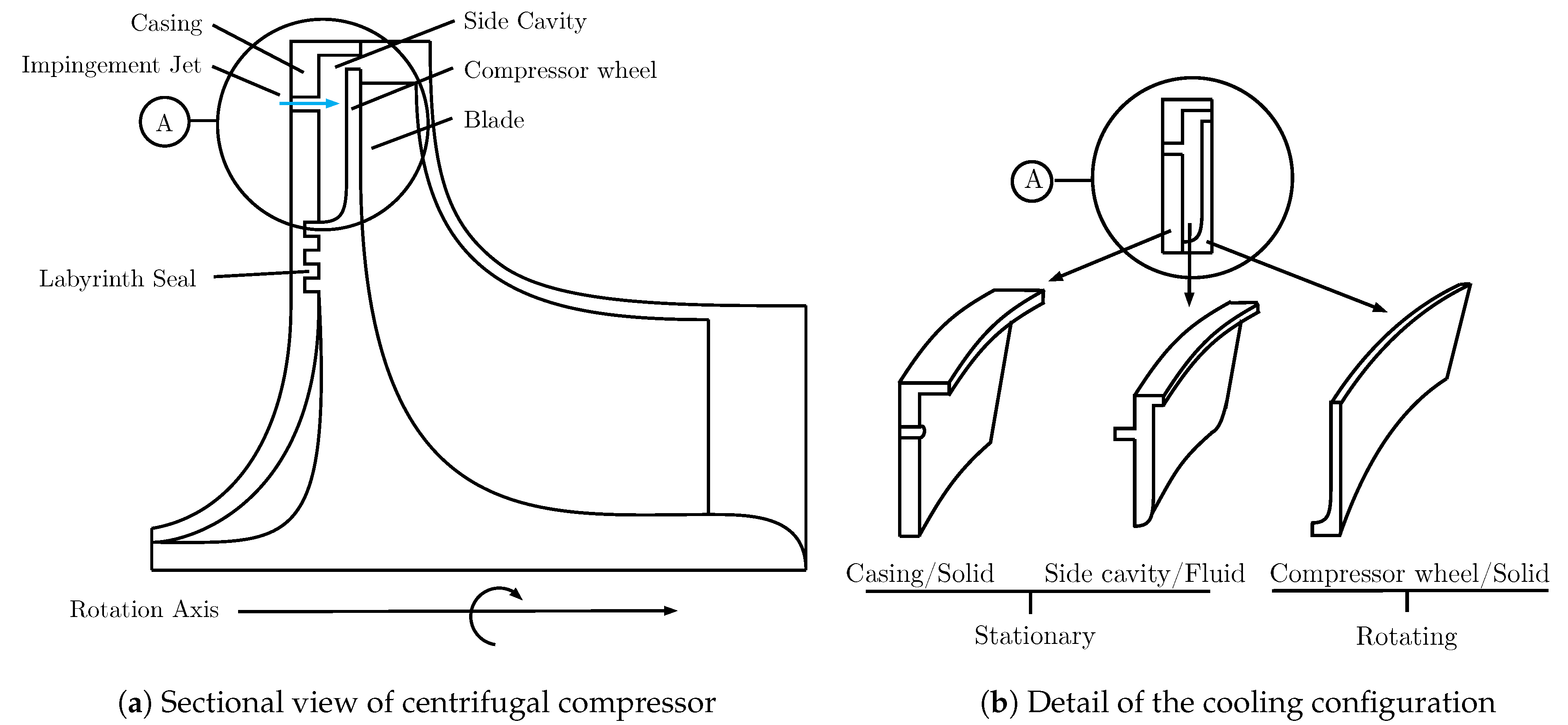
19], assuming that the upstream-component outflow quickly mixes out in circumferential direction, so that the downstream component “only” sees a circumferentially averaged state. This approach directly transforms the physically unsteady situation in a steady one from the numerical side. Using the same idea, a fluid-solid mixing-plane interface is proposed in order to obtain time-averaged results for CHT problems. The concept is introduced based on a schematic description of the impingement cooling on a centrifugal compressor given in
Figure 1.
Figure 1a shows a sectional view of a centrifugal compressor setup with jet impingement cooling. The cooling jet enters the side cavity through the stationary compressor casing and impacts on the hot compressor wheel. The region of interest is highlighted in
Figure 1a as region
A with the exploded view in
Figure 1b. The periodicity of the stationary casing and side cavity segment depends on the number of cooling holes and is, therefore, identical. With both domains being stationary, the coupling between these two regions can be achieved through well known standard CHT interfaces. The benefit of the proposed method is in the discretization of the interface that couples the stationary fluid side cavity with the rotation solid compressor wheel. Using a mixed out representation of the fluid-solid heat flux would allow us to connect these periodically different domains and render the problem steady state.
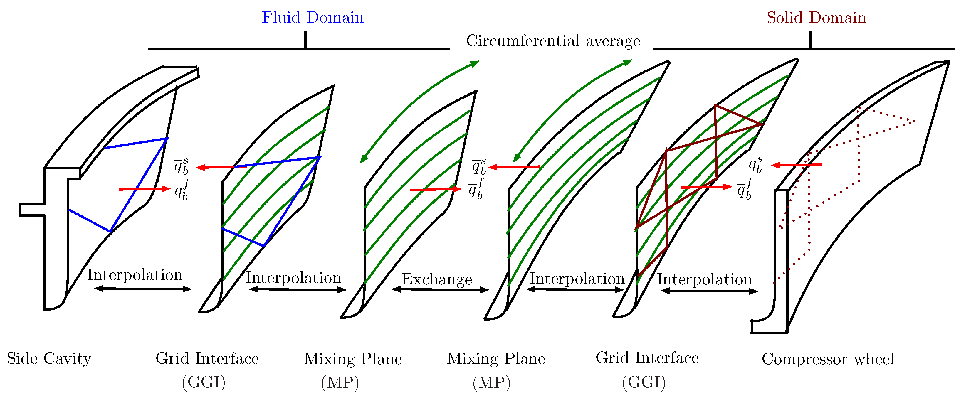
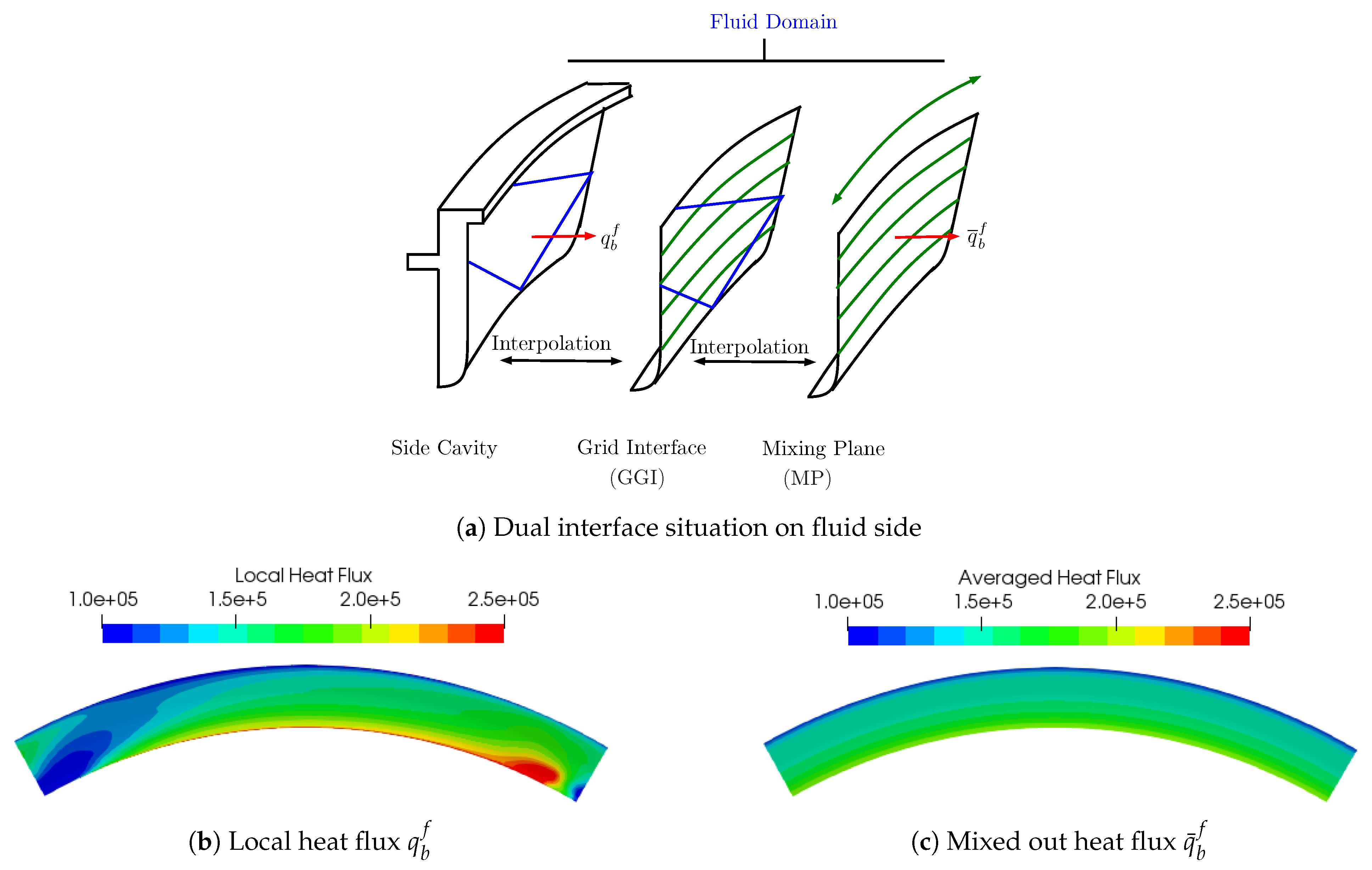
The method is schematically described in
Figure 2. A cooling jet passes through the side cavity of the centrifugal compressor and impinges on the back wheel of the impeller. However, different to a fully transient analysis, the side cavity is connected to the compressor back wheel through two mixing plane interfaces. The heat flux, transferred from the fluid to the solid, is, therefore, initially interpolated on the structured mixing plane (MP) interface through what is generally known as general grid interface (GGI). These interfaces allow the connection of different mesh structures. In a second step, this interpolated heat flux is averaged circumferentially and a steady state representation is given. The low timescale of the diffusive transport of heat inside the solid, together with the high rotational speed of the impeller, justify this approach. Measurements showed that the temperature at a given radius does not vary circumferentially.
This concept was first introduced in Reference [
20] inside of a commercial software with a relevant limitation: the heat flux was averaged after each outer iteration using an external tool and used thereafter as the new boundary condition. The averaged heat flux was, thus, a fully explicit contribution to the right-hand side of the linearized equation system. To avoid sudden changes in the boundary conditions from one iteration to the next, small time steps have to be chosen to maintain stability of the solution procedure.
In this article, this explicit CHT mixing plane (ECHT-MP) will be extended to a novel, fully implicit fluid-solid CHT mixing plane interface (ICHT-MP) to overcome the drawbacks of the previous formulation. The implementation in an in-house code is based on the general description of a fully implicit fluid-fluid mixing plane presented in a previous publication [
21] which was proven to provide accurate results and being numerically robust even at off design conditions when flow reversal occurred. First, the derivation and methodology are described. In a second step the model is used for a real centrifugal-compressor application. The results are then compared to those of a transient model and validated with experimental data, as well as the explicit CHT mixing plane (ECHT-MP) of Reference [
20].
3. Numerical Framework
In this section, the used in-house numerical framework is quickly introduced. The general fluid-fluid mixing plane concept is reviewed with respect to the already published fully implicit mixing plane formulation. The concept of the implicit averaging technique is then extended to fluid-solid CHT setups.
3.1. Coupled, Pressure Based CFD Algorithm
At the core of any CFD solver is the integration of the pressure-velocity coupling present in the Navier–Stokes equations. While the majority of developments was dedicated to solution procedures solving the momentum and continuity equations sequentially (segregated), recent developments have proven the superiority of the so called coupled approach that solves these equations simultaneously. Overall computational time for CHT computations is, therefore, not only affected by the fluid-solid coupling but also depends heavily on the solution strategy for the fluid part itself. This becomes especially true, once the time scale of the solid is not the limiting factor for the overall computational time. The coupled in-house code is written in C++ 17 and based on a block coupled pressure-based framework [
22,
23,
24].
3.2. General Description of the Mixing Plane Approach
The basic concept of the proposed CHT mixing plane is based on a novel fluid-fluid mixing plane approach presented in previous papers by References [
21,
25], which was motivated by several drawbacks of the available methods. In general, the mixing plane is a way to reproduce the time-averaged (i.e., stationary) impact of the transient rotor-stator interaction by mixing out the flow at the rotor-stator interface in circumferential direction. This not only allows to avoid costly transient simulations through steady-state computations, but also enables to perform computations using single passages of the components in cases of varying pitch between the stages. As a consequence, the use of mixing planes can reduce computational costs drastically.
While the basic working principle of mixing planes is clear, the physical derivation and numerical implementation allows great freedom. The most obvious and simplest approach is the use of explicit boundary conditions [
26,
27]. These boundary conditions split a physically connected domain into a numerically separated one. This is not only detrimental to the stability of the iterative solution procedure; it also rises questions on how to consistently evaluate primitive variables, such as pressure, velocity, and temperature, in order to fulfill the conservation equations.
An attempt to improve the behavior of explicit mixing plane interfaces are, e.g., the use of Dzung’s averaging technique [
28], to obtain primitive variables that better represent the conservation equations. This increase in accuracy has to be paid with a higher complexity of the code leading to a decrease in the robustness of the algorithm. Comparison between an explicit implementation using Dzung’s average and the novel implicit mixing plane approach was demonstrated by the authors in Reference [
21]. Computations with a centrifugal compressor stage clearly show the superior behavior of the implicit approach in terms of accuracy, robustness and computational speed.
The present paper describes the process to transfer the known benefits of the implicit fluid-fluid mixing plane coupling to fluid-solid CHT configurations. The derivation of the method is explained in the following sections.
3.3. CHT-Mixing Plane: Numerical Discretization
Similar to the fluid-fluid mixing plane introduced in Reference [
21], the fluid-solid mixing plane can be achieved by circumferentially averaging the coupling of the energy equation at the solid-fluid interface. The steady state representation of the energy equation for the conservation of total enthalpy is given in Equation (
1).
In a finite volume-based numerical scheme, this differential equation is integrated over discrete volumes using Gauss’s theorem, leading to a series of summations over the faces of these volumes as given in Equation (
2).
The basic constraint for the heat exchange between the solid and the fluid is the conservation of the heat flux
, i.e., the wall normal heat flux has to be the same from either side, finally leading to Equation (
3). The superscript
s stands for solid and
f for fluid, while
i refers to the interface face between the two regions.
With respect to the proposed CHT-mixing plane approach, this constrained has to be analyzed with respect to what was methodically described in
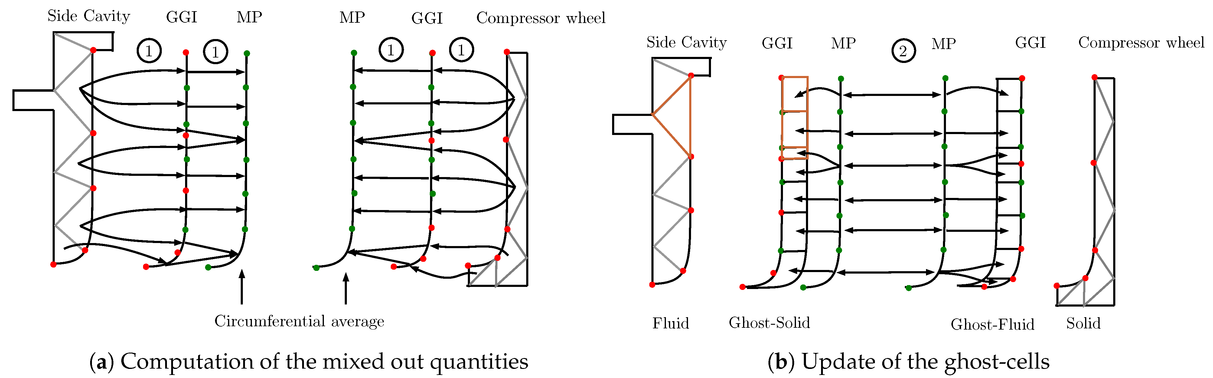
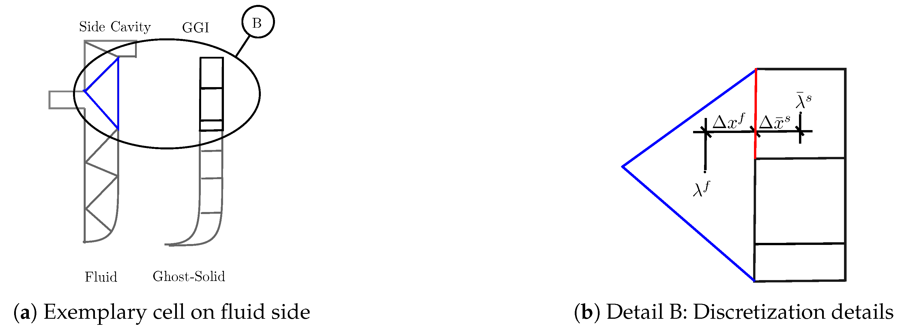
Figure 1. The details of the derivation are explained based on a 2D representation given in
Figure 3. Starting with
Figure 3a, the gray lines define the control volume faces in the fluid side cavity and the solid compressor wheel. The CHT boundary of each of these computational domains is connected to a structured mixing plane (MP) through a general grid interface (GGI) that allows for an interpolation between the physical boundary and the virtual mixing plane interface. In a first step, this GGI is used to compute and update any quantity that needs to be exchanged between the two computational domains and is interpolated on the structured MP. The MP is then used to compute the circumferential average of the respective quantity. In a second step, these quantities are exchanged between the MP planes and interpolated on what we call ghost cell on the GGI of the respective side.
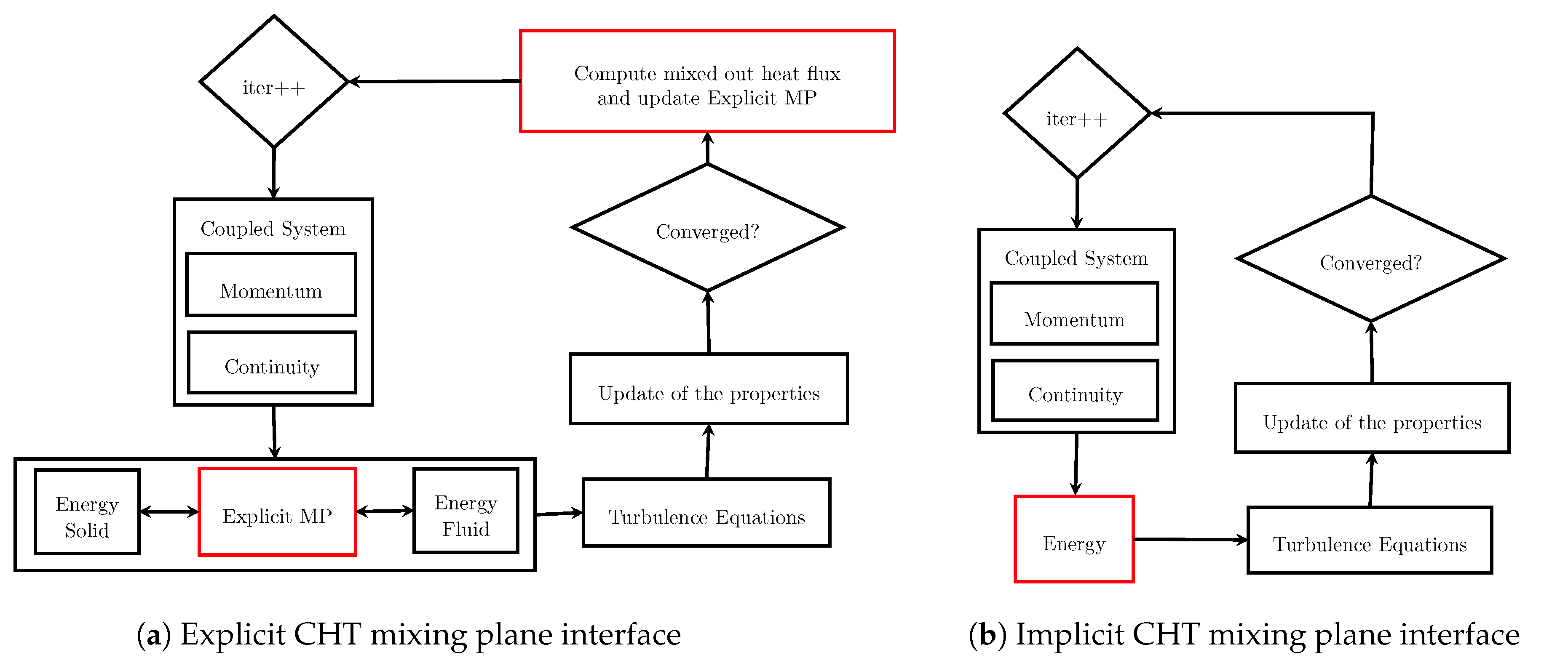
In order to further outline the difference between the previous CHT mixing plane concept of Reference [
20], the flow chart of the iterative solution procedure is compared against the proposed method of this article in
Figure 4.
The explicit implementation of the former CHT mixing plane concept of Reference [
20] is described based on what is given in
Figure 4a. With the heat flux at the solid-fluid interface being an explicit contribution to the right-hand side of the linearized equations system, the energy equation is, therefore, numerically completely separating the two computational domains. Even though they are assembled into the same coefficient matrix and solved simultaneously, the connectivity is not represented on the left-hand side. The update in the heat flux passing through the CHT interface is then computed externally using a procedure as described in
Figure 3, however, directly averaging the heat flux
. The proposed implicit CHT mixing plane follows a different approach. What is needed is an implicit discretization of the mixed out exchanged heat flux at the interface. An external update of the boundary heat flux is replaced and a fully coupled linearized equation system is found for the energy equation. Hence, the implicit flow chart is described in
Figure 4b.
In
Figure 3b, an exemplary fluid cell is already highlighted for the following derivation of the implicit discretization. The same procedure applies for any solid cell during the assembly of the heat flux.
Figure 5a repeats the situation for this exemplary fluid side discretization together with the ghost cells that represent the mixed out solid cells. The most important parameters for the later implicit discretization of the CHT mixing plane interface is given in
Figure 5b. In this figure,
is the conductivity,
the normal face to cell-center distance, and the overbar indicates the mixing procedure explained in
Figure 5b. During the Gauss integration of the fluid cell, instead of applying the surface integration to the single fluid boundary face, the integration is carried out over the faces connecting the fluid cell to the solid ghost cells. Quantities, that have been computed using the two-step dual interface mixing plane procedure, are marked with an overline as
.
Using Fourier’s law on the constraint for the conservation of the interface heat flux given in Equation (
3), a new expression is found as given in Equation (
4).
The definition of the temperature at the interface to the shadow cell is, therefore, found as given in Equation (6).
Therefore, when assembling the heat flux in the energy equation at a cell attached to a CHT mixing plane, the heat flux is computed as given in Equation (8). The equation is given exemplary for the fluid cell highlighted in blue; however, the procedure is applied identically on the solid side.
This concept is then applied for all remaining boundary-attached cells on the fluid and on the solid side, in order to obtain the coefficients to implicitly describe the dependency between owner and neighbor cells at the interface, thus solving the solid and the fluid domain in one single coefficients matrix.
4. Results
The proposed fully implicit CHT-MP is implemented in an in-house numerical framework using the coupled approach described above. Since validation is carried out against full transient solutions using a coupled commercial code, the following notations are introduced:
As already stated in the section introducing the used in-house framework, the developed numerical algorithm uses a so-called coupled algorithm, hence solving the momentum and continuity equation simultaneously. The same accounts for the used commercial code that was used as a reference for the validation.
4.1. Computational Domain and Numerical Setup
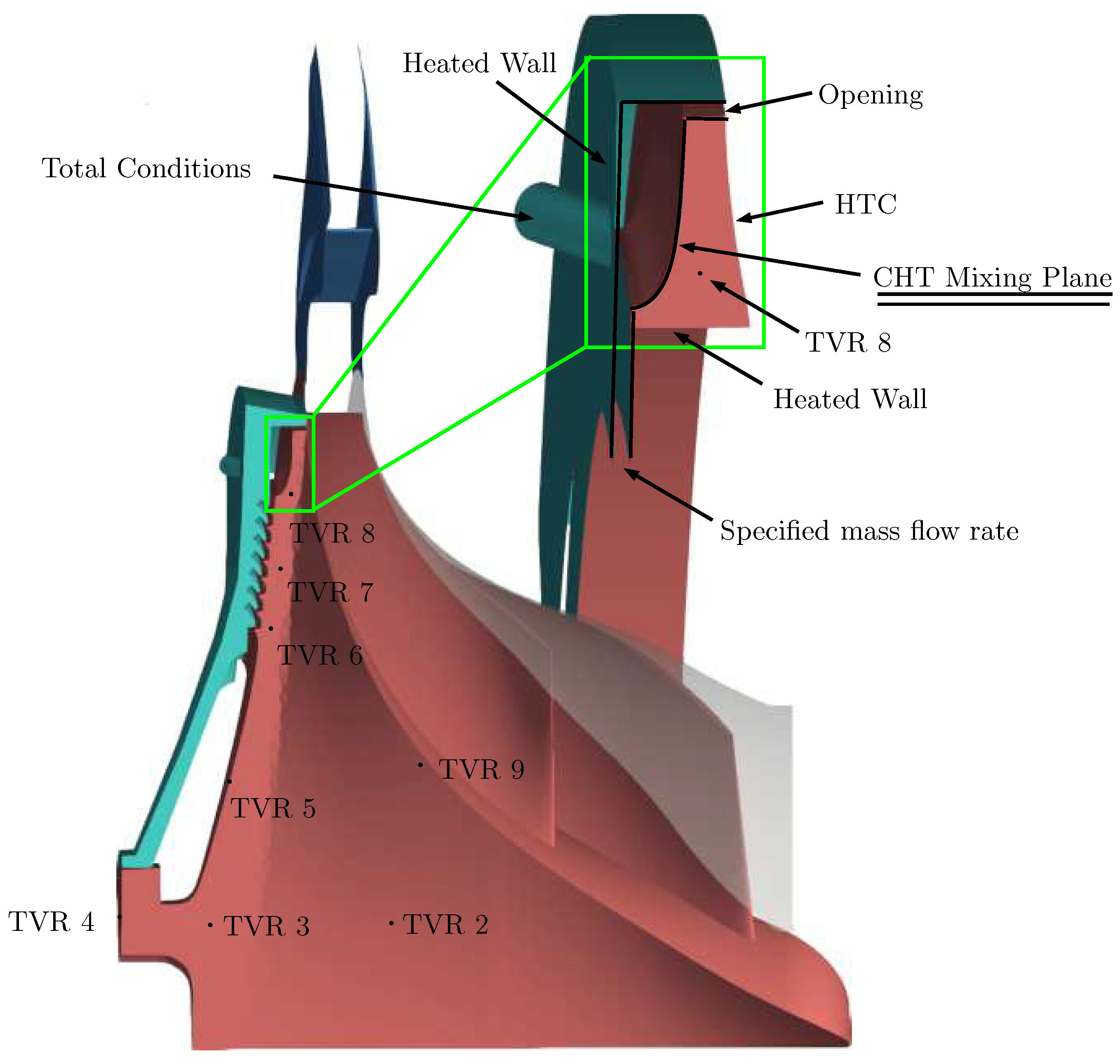
The compressor setup is given in
Figure 6. During the measurement campaign, eight different temperature sensors (TVR2–TVR9) were installed. Due to the availability of this extensive measurement data, a further reduction of the domain was possible for the validation of the chosen CHT-MP approach. For this particular case, the periodicity could be adopted for the unsteady computations. The computational domain is a 60° section highlighted in green, covering the location of measurement probe TVR8 for the later comparison.
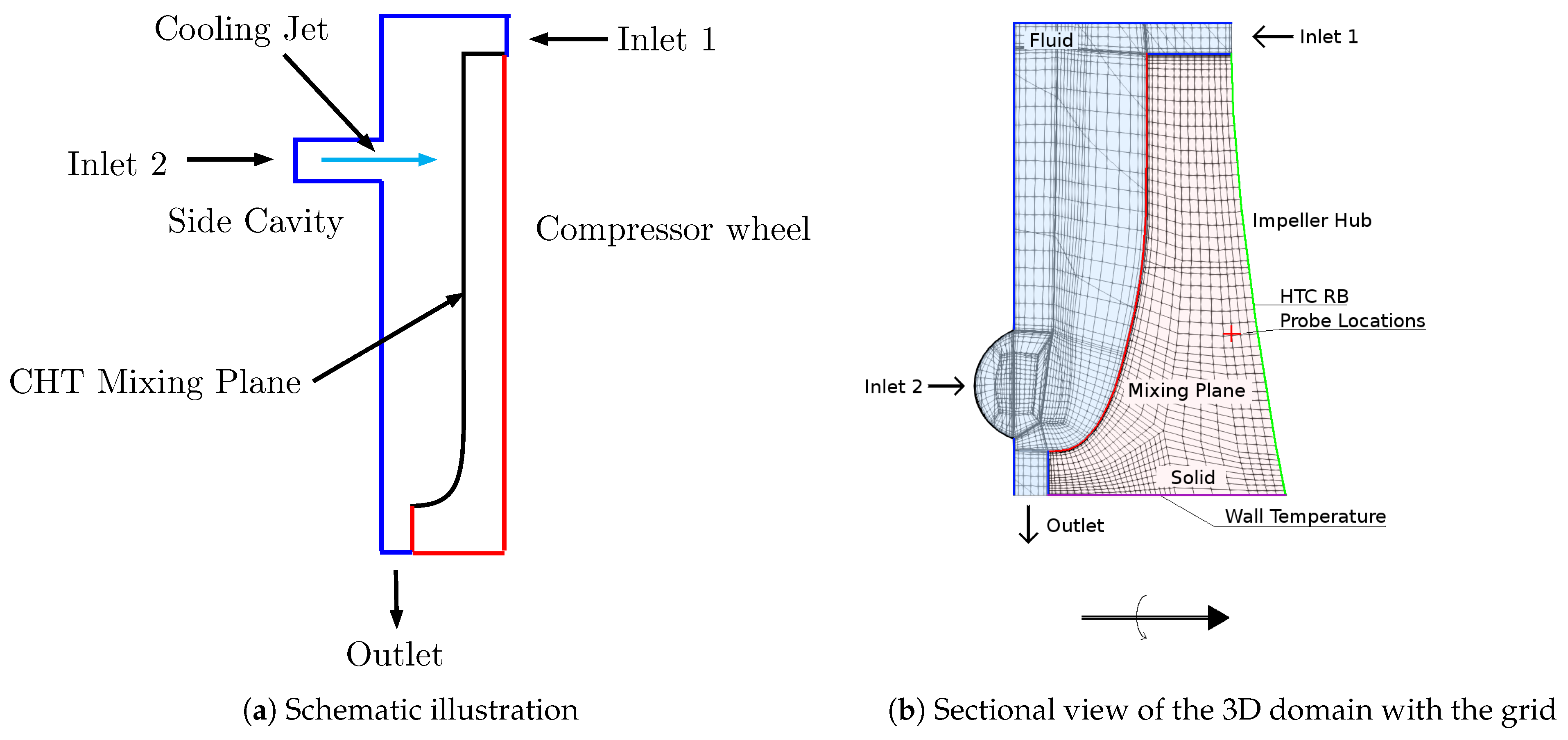
The boundary setup is given in
Figure 7 also showing the computational mesh. A mesh study describing the dependency of the solution on the grid resolution for this specific case was already carried out in Reference [
20] and, therefore, not repeated here. The results showed that for the presented thermal analysis, the viscous sublayer should be resolved. The mesh, consists of approximately 2mio hexahedra cells with a
value of around 4.
4.2. Validation
Validation is performed with both experimental and unsteady numerical data. For comparability, the same computational domain is used for the fully transient analysis, as well as for the steady CHT-mixing plane simulations. Improvements in computational time would, therefore, become even more dominant in standard jet-impingement cooling applications if the use of periodicity would not be possible, thus requiring full annulus computation.
For the fully transient analysis, the solid part is moving based on chosen time step and rotational speed of the impeller for the given operating conditions. A sliding mesh interface is used for the coupling between the solid and fluid domain. The steady state computations are performed using the developed implicit CHT mixing plane (ICHT-MP), thermally coupling the fluid and solid regions. Since in this case no rotation of the solid domain is necessary, a rotating wall velocity is imposed at the mixing plane location. The heat flux from the compressor side to the impeller wheel is modeled using a HTC boundary condition. The surface at the exit of the impeller wheel uses an opening type boundary condition, because depending on the operating conditions, flow reversal can occur. For the impingement jet, total temperature and mass flow are imposed, while, at the outlet the mass flow rate is prescribed. At the remaining walls, the temperature is imposed. Except for the HTC boundary condition, all imposed values are extracted from measurement data. The value for HTC is obtained from a full 360° numerical simulation.
4.3. Validation: Accuracy of the Results
In order to validate the proposed methodology, a comparison to experimental and unsteady CFD data obtained in Reference [
20] is performed. All results are non-dimensionalized by the design operating conditions (OP1) using the experimental values. Two setups have been computed, one using full load (100% machine speed) and another at part load (90% machine speed). For each of these operating points, three different coolant flow rates have been specified. The operating points and names are summarized in
Table 1, with
being the actual coolant mass flow of the impingement jet at the chosen operating point and
being the design coolant mass flow.
OP3 and OP6 are uncooled configurations and are, therefore, not included in the following results. However, since the previous results obtained using the explicit approach [
20] are not repeated here, the nomenclature in the operating points is kept to be consistent with the labeling used therein. Additionally, as stated in Reference [
20], the experimental temperature measurements in the rotating frame of the blade wheel were extremely challenging leading to some failure of the measurement equipment. This is the reason for the missing experimental data for OP1.
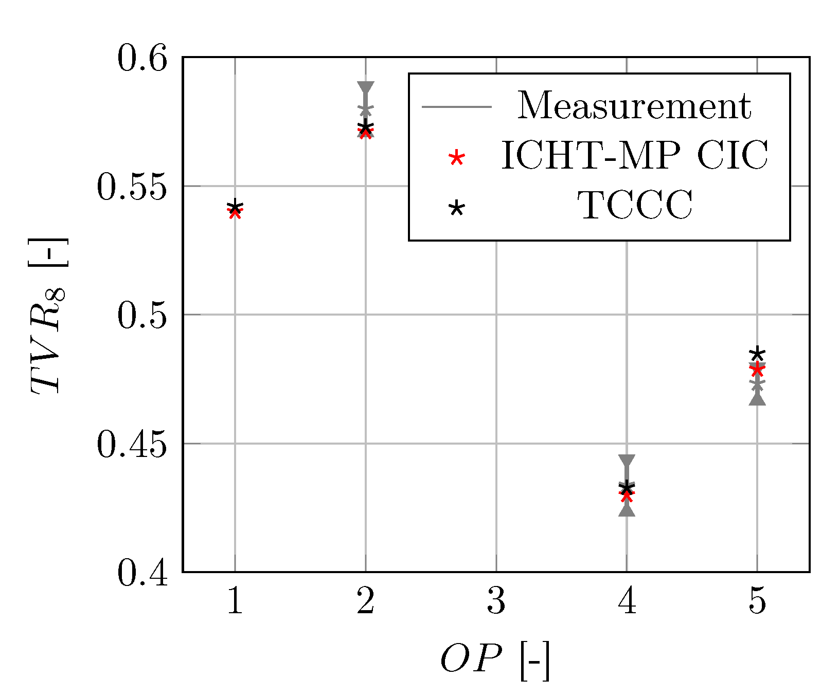
Figure 8 shows the normalized temperature at position TVR8 for the four operating points (OP1, OP2, OP4, OP5). Measurement data is given in gray, with error bars describing the associated uncertainty. Black marks correspond to time averaged results of the fully transient computation using sliding mesh interface (TCCC). Finally, the red marks are the results obtained using the proposed implicit CHT mixing plane with the coupled in-house code (ICHT-MP CIC).
All results obtained using the steady state approach using the CHT-MP are in very good agreement with the transient results. The numerical values for non-dimensional wheel temperature (TVR) are in the range of the uncertainty of the measurement campaign.
4.4. Validation: Conservation of the Averaged Heat Flux
The full dual-step mixing plane procedure for the interpolation of the mixed out heat flux was already schematically depicted in
Figure 2. In order to illustrate the outcome of this mixing process and to further access the conservation of the exchanged heat flux, the outcome is provided in
Figure 9. The illustration in
Figure 9a schematically describes the investigated situation. The local heat flux at the fluid boundary is given in
Figure 9b corresponding to
in
Figure 9a as extracted from the numerical solution. The averaged, exchanged heat flux is then given in
Figure 9c corresponding to
in
Figure 9a. With the conservation of the heat flux being the basic constraint given in Equation (
3), it is ensured, that the exchanged quantity is preserved through the interface.
4.5. Validation: Computational Time
While proving the accuracy of the presented fully implicit CHT-MP is clearly a necessity for the applicability of the approach, the main motivation behind the presented work was a reduction of the computational costs of CHT computations for turbomachinery applications to allow the use of the approach as a design tool. This section is, therefore, intended to summarize the results with respect to this subject.
An earlier implementation of an explicit version of a CHT-MP (ECHT-MP) in Reference [
20] has already proven the capability of such procedure to not only reproduce accurate time-averaged results but also greatly improve the computational time and costs.
Table 2 summarizes the findings in terms of computational time for a single operating point by means of a reduction factor. Reference [
20] reported a reduction factor of 17 for their implementation of the ECHT-MP into a coupled commercial code. These finding encouraged the implementation of the ICHT-MP into a coupled solver framework. For the current configuration with a low Reynolds mesh, an overall reduction factor of approximately 800 compared to the fully transient coupled simulation using commercial code (TCCC) was achieved. Using the ICHT-MP to allow for steady state solutions, no relaxation is needed in the solid domain, thus being the overall computational time only depending on the convergence rate of the numerical solution inside the fluid domain.
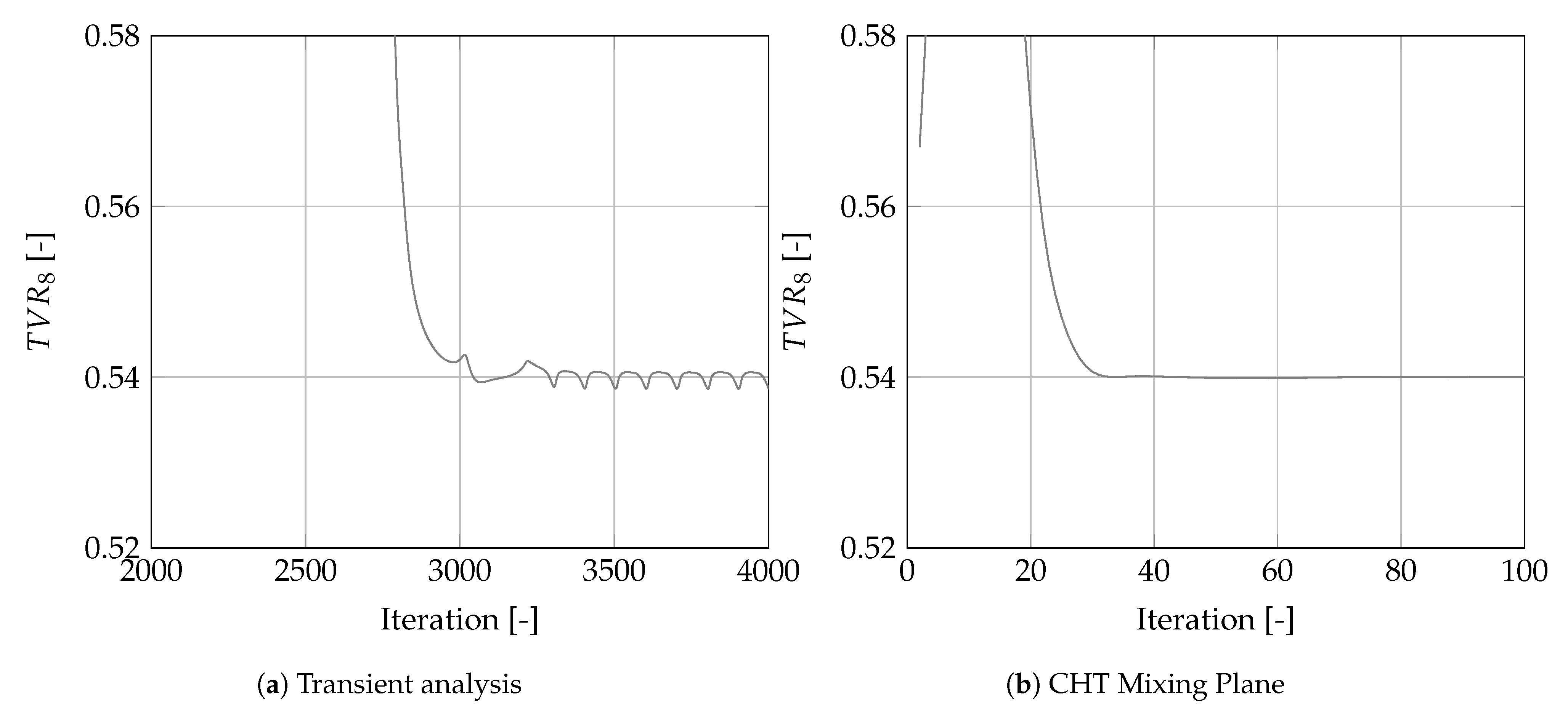
These findings are further outlined in
Figure 10, showing the convergence behavior against iterations of the temperature at the investigated probe location. It needs to be mentioned that the iterations for the transient analysis are the outer loop time steps, for each time step there is an additional amount of inner loops. As can be seen from
Figure 10a, it takes a considerable amount of time until the solution starts to oscillate around the quasi steady solution. Once this solution is obtained, the time-averaged solution is computed, requiring additional time steps. Using the proposed CHT mixing plane, the steady-state solution is found much faster, and no averaging is required thereafter (
Figure 10b).
5. Conclusions
In this paper, the development of a novel, fully implicit fluid-solid CHT mixing-plane interface has been presented. The proposed approach allows, with a similar procedure as for the fluid-fluid mixing plane, to simulate inherently unsteady CHT problems with steady state simulations. This makes the methodology particularly interesting when time-averaged solid temperatures are of interest, like, for example, on rotating disks cooled by jet impingement. Extensive validation using transient CHT simulations and measurement data does not only prove the accuracy of the developed approach but also a drastic impact on computational costs.
It was demonstrated that the ICHT-MP, together with the coupled in-house code, is capable of accurately reproducing the fully transient results obtained using a coupled commercial code for all four operating points of the given validation configuration. Additionally, all results are within the measurement uncertainty, proving the applicability to real scale engineering applications.
The major target of the proposed implicit CHT coupling through a mixing plane, which was a reduction of computational costs, was clearly achieved. In terms of computational time, the steady-state fluid-solid mixing plane approach drastically reduces the effort compared to a “classical” unsteady CHT simulation (i.e., same time for fluid and solid) by a factor of 800 with a coupled solver. As stated earlier, on this simplified case, it is possible to run transient analysis with periodic boundary conditions. For real compressor cooling configurations, this reduction is only possible when using steady-state computations based on the CHT mixing plane. Therefore, for the general case of compressor wheel impingement cooling, the reduction in computational time can be expected to be even higher.
Overall convergence is only defined by the convergence rate of the solution in the fluid domain, an issue which is addressed by the use of coupled solution strategies in the used framework. Using a coupled solver clearly emphasizes the advantages of using a steady-state approach: (1) it allows to compute the solid with very large time steps, and (2) convergence with low-Re meshes, necessary for heat transfer simulations, is not affected by large aspect-ratio cells as it is in segregated solvers.
This approach is, therefore, particularly attractive in the design phase, making it possible to assess time-averaged solid temperatures subject to unsteady cooling, since the time requirement for a CHT steady-state simulation is reduced by factors compared to a full unsteady computation.


 ,
, 


