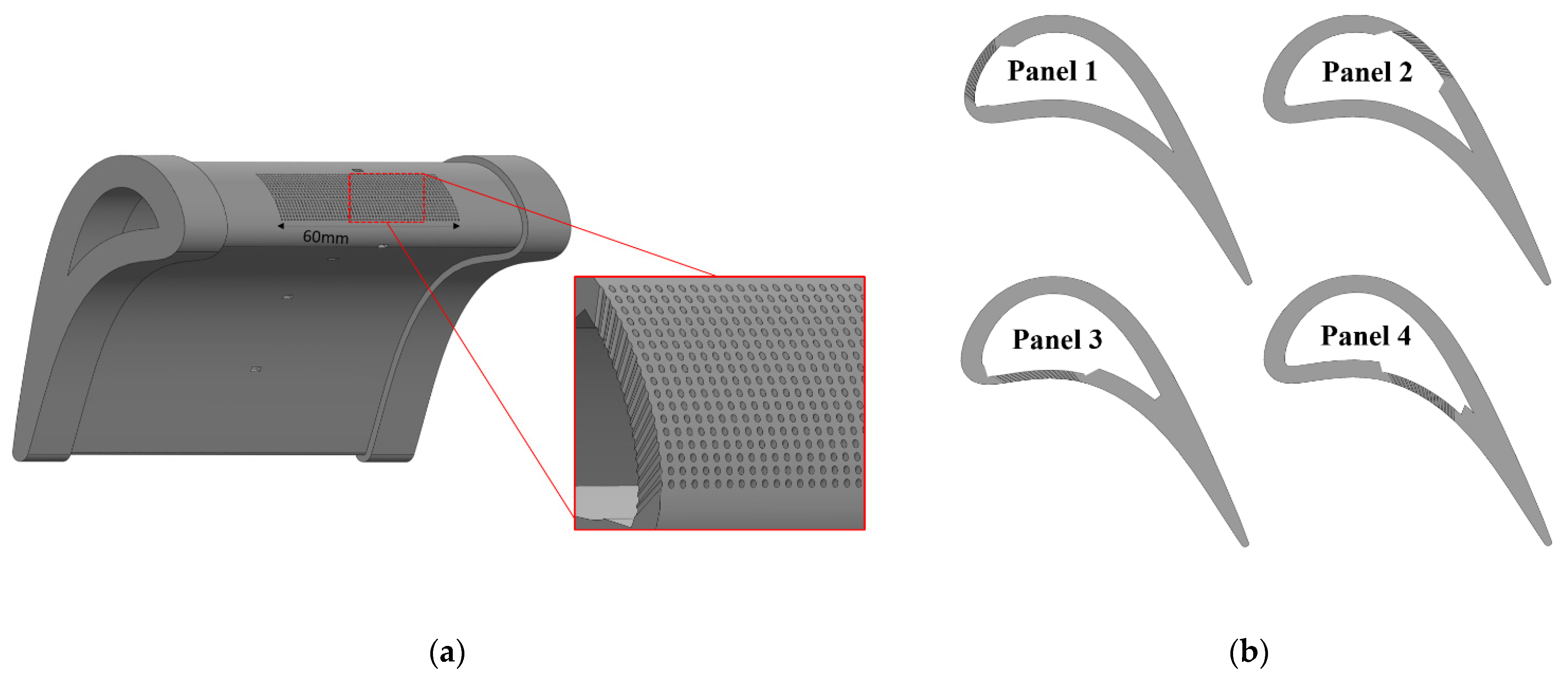
5.1. Varying Panel Locations
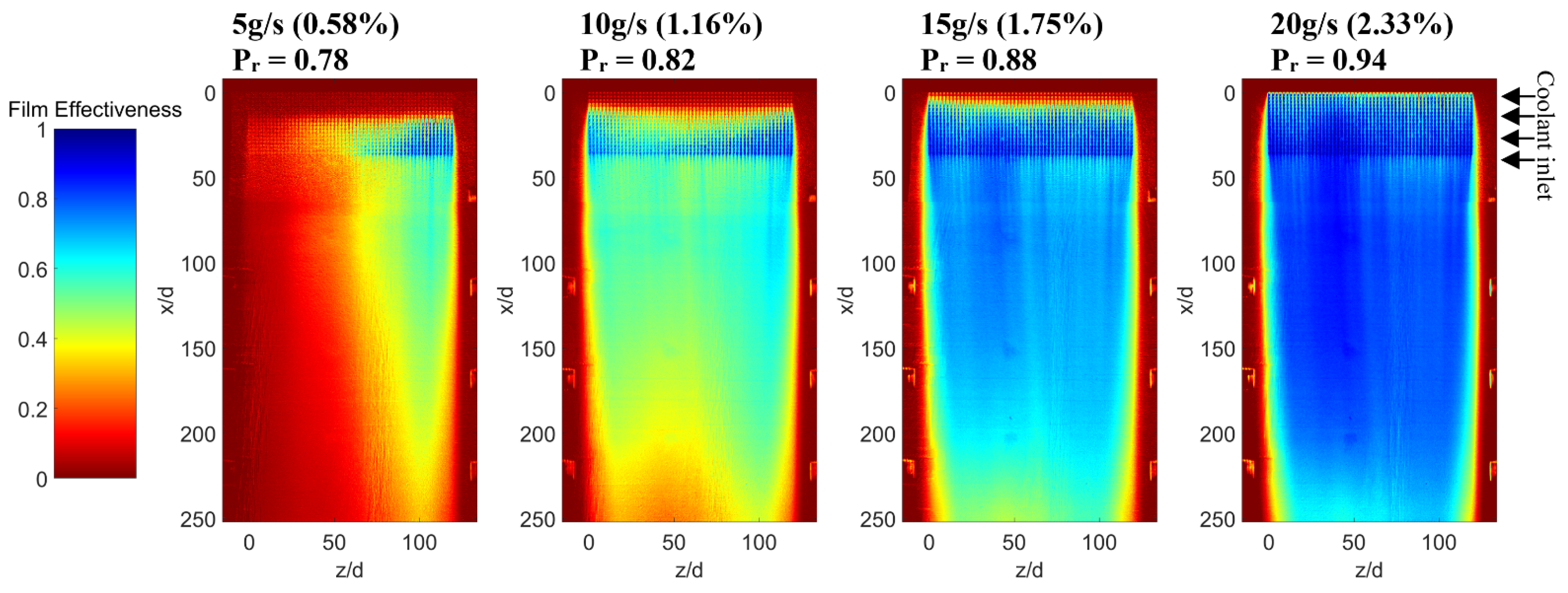
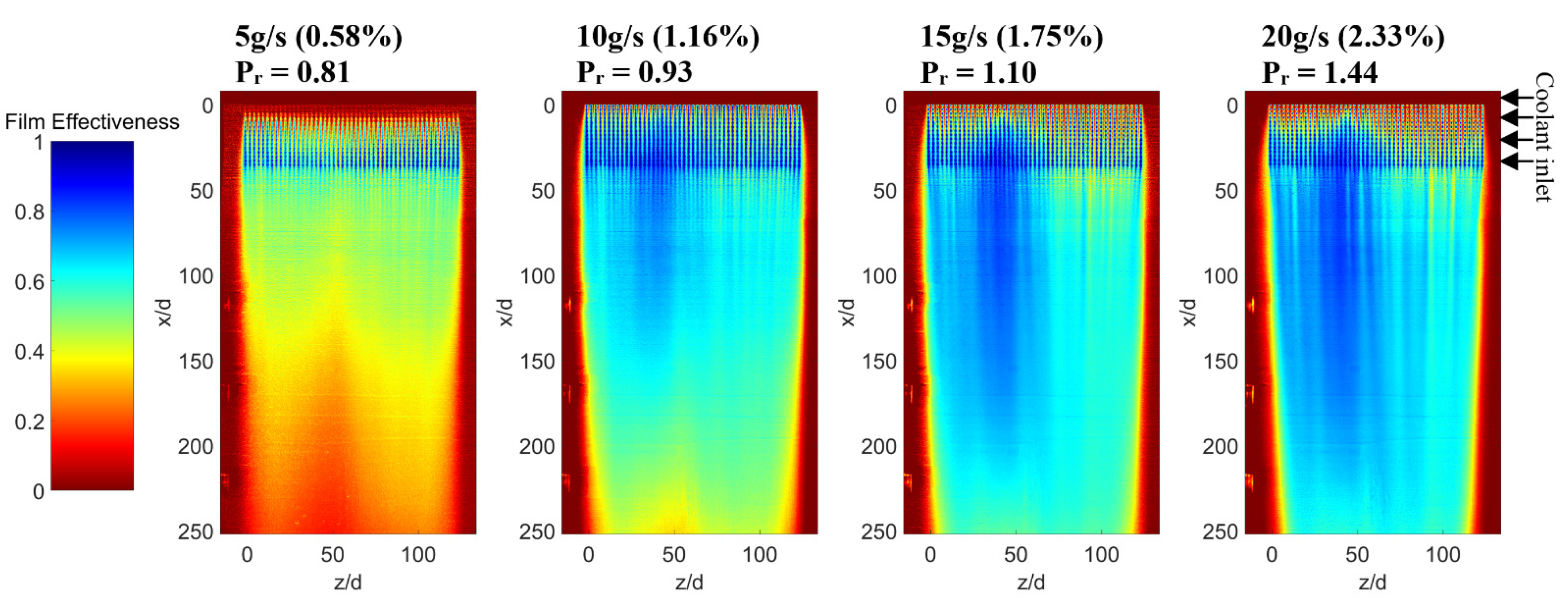
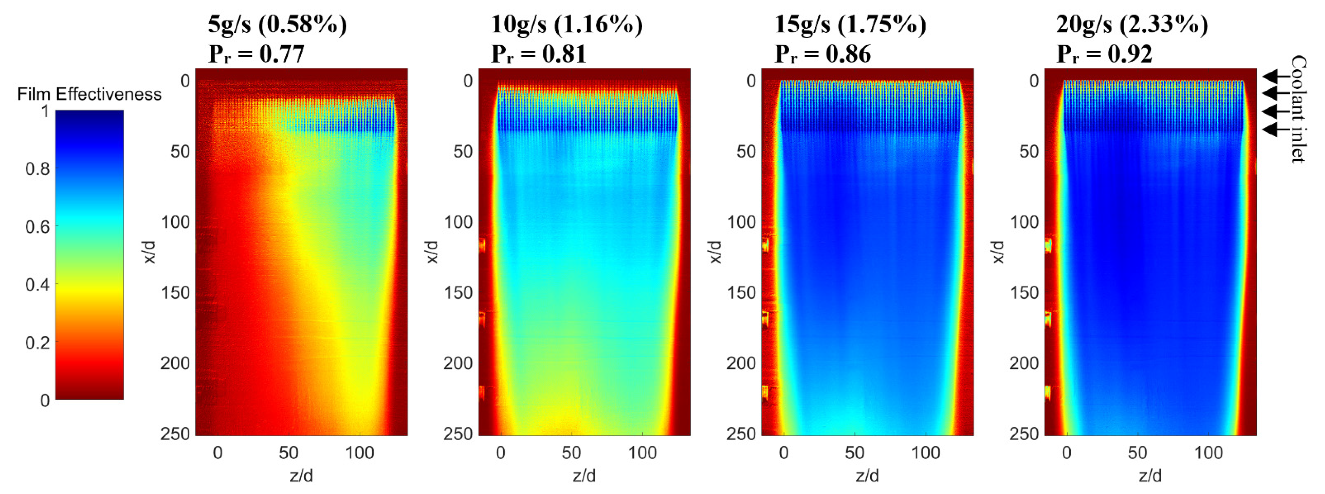
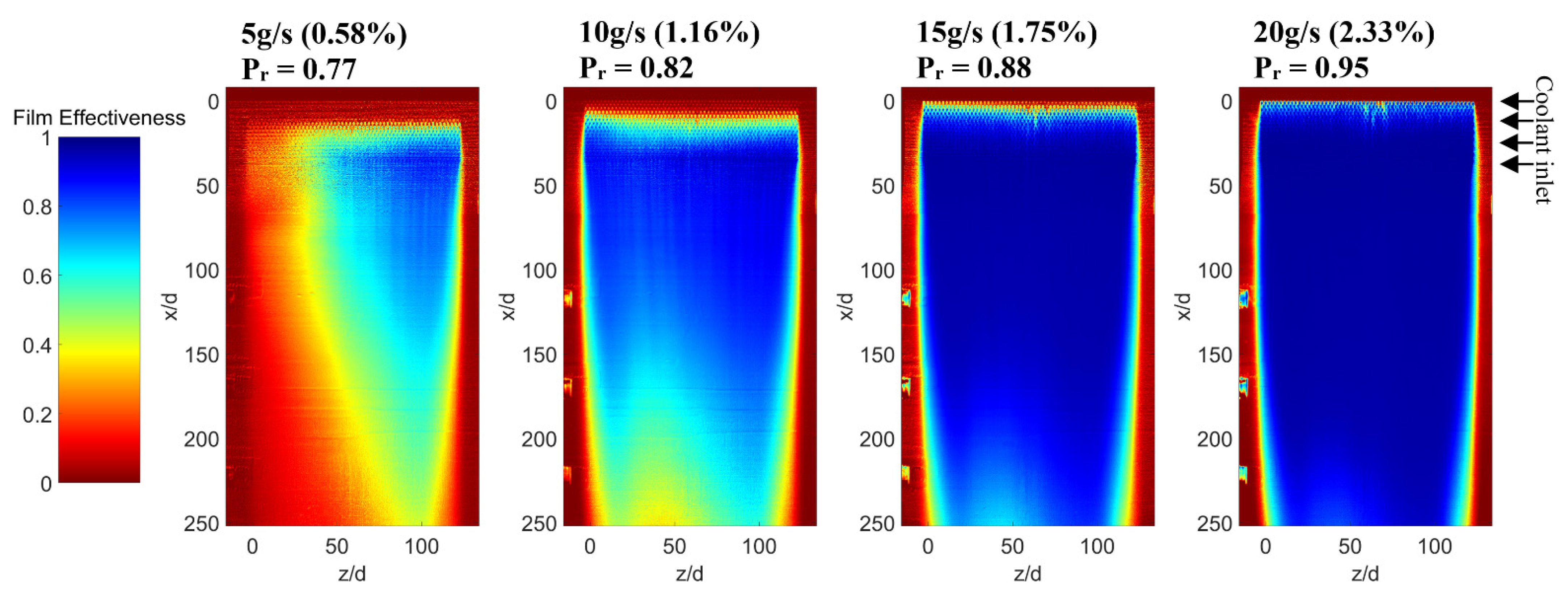
First, the film effectiveness map of Panels 1–4 across four different blowing rates are shown in
Figure 2,
Figure 3,
Figure 4 and
Figure 5 respectively. The charts show the entire width of the blade surface from the start of the panel at x/d = 0 down to the trailing edge. The ratio Pr between the coolant and mainstream inlet total pressures is also shown. The plots are arranged so that the coolant is always being fed from the right side of the image.
For all panels at low blowing rates, film distributions are uneven with coolant only being ejected from certain sections of the panels. This is mainly due to the significant external static pressure variation along the streamwise dimension of the panels. This favors flow towards the trailing edge of Panel 1, 2 and 4, and towards the leading edge of Panel 3, where a mild adverse pressure gradient occurs. The low internal pressure results in significant ingestion across the panels. Furthermore, variations in internal static pressure and coolant velocity within the blades lead to uneven spanwise distributions.
As the coolant flow rate is increased, the distribution is first matched in the spanwise direction and, as the internal blade pressure is further increased, coolant is observed being ejected by every row.
Due to the high resolution of the PSP, the films of the individual holes can be differentiated from the bulk of the coolant. These individual features mix out within a short distance of the end of the panels. On the other hand, the bulk of the panels form a much more robust sheet film.
At the highest mass flows, Panel 1 demonstrates an almost continuous unbroken film, with the entire region downstream of the panel being of a similar film effectiveness. Once above 5 g/s, the entire span of the panel is fed with coolant, increasing the coolant fraction raises the film effectiveness uniformly across the entire area. This is a sharp contrast to Panel 2, where a higher film effectiveness is achieved immediately downstream of the panel but quickly falls off. Increasing the coolant fraction slowly extends the film further downstream, requiring a higher coolant fraction in order to obtain high levels of film effectiveness at the trailing edge.
The difference in films between the two panels can in part be explained by the differences in local mainstream flow. Panel 1, shown in
Figure 2, is located in a region of high convex curvature and a significant portion of the downstream region is also convex. Furthermore, these films experience a very high favorable pressure gradient near the panel region. These two effects, combined with the low blowing ratio of the individual holes, result in the films remaining very close to the surface of the blade, with minimal decay. Any disturbances created by the small film jets are small enough to be stabilized by the larger dominant behavior of the mainstream flow. The rate of film decay only begins to increase near the trailing edge region where the curvature flattens out and the flow begins to slow down, increasing the boundary layer thickness as well as the turbulent mixing, resulting in a loss of measured film effectiveness. Evidence of this can be seen in both Panels 1 and 2; the films appear to narrow near the trailing edge as the boundary layers of the sides of the rig grow and push the films toward the middle.
As Panel 2 is positioned further back, it can be seen from
Figure 3 that it does not benefit from the early features of the suction surface. On top of the reversal of the pressure gradient, the Mach number at Panel 2 approaches 0.8, resulting in much more significant film to mainstream interactions within the panel itself.
The two pressure surface panels share a similar trend and distribution with a few notable differences. Both significantly favor the left side, most likely due to the higher internal static pressure inside this half of the blade, opposite the coolant feed. At higher mass fractions, the films start at very high levels but drastically fall off, particularly in Panel 3. This suggests the films follow a trend similar to the wall jet model, with a section of strong potential core in which the film remains mostly untouched by the mainstream, followed by a region of turbulent mixing, which typically dominates most conventional film behavior.
Figure 4 of Panel 3 demonstrates high levels of lateral mixing as the film does not manifest any features reminiscent of the individual holes. In contrast,
Figure 5 demonstrates that Panel 4 behaves more like the suction surface panels, with definitive streaks being visible, particularly at the higher mass fractions. This behavior is indicative of the high mainstream flow velocity and strong pressure gradient which dominates the flow. Beyond demonstrating a lack in lateral film spreading, the streaks are also indicative that the panels are not entirely successful in pushing the mainstream away from the surface of the blade as is typically expected in transpiration designs. The square arrangement of holes allows for streams of mainstream air to penetrate through the panels. This is best illustrated in Panel 4 at 15 and 20 g/s, where visible wakes of mainstream air can be seen compromising a large portion of the downstream film.
Despite these limitations, the overall film effectiveness of all panels remains high for even modest mass flow rates. Once the bulk film is established over the entire span of the panel, a very high average effectiveness is achieved by the spanwise uniformity of the film. This differs from typical film cooling designs that contain hot streaks between film cooling holes, greatly increasing the film to mainstream contact area.
The spatial data can be averaged out laterally, pixel by pixel, in order to obtain a spanwise average of the films as shown by
Figure 6. The averages are only performed over the 120 z/d midspan of the blade containing the transpiration panel. These plots allow for a greater analysis in the behavior of the films. In these plots the panel location is also indicated by the shaded area.
Immediately downstream of the panels, particularly on the suction surface, film lift-off can be observed. While the average blowing ratios of either panel does not exceed 0.3, the rows furthest downstream have a higher blowing ratio and the films require approximately 15 d to recover.
When compared to the other panels, Panel 1 undergoes a much lower rate of film decay, to the point at which the film effectiveness at the trailing edge is higher for Panel 1 than for Panel 2 for the same mass flow rates. Naturally, the blowing ratio of Panel 2 is lower than that of Panel 1 due to the higher mainstream velocity, yet the fact remains that the suction surface trailing edge is better served by Panel 1 than Panel 2, suggesting a fundamental difference in the structure and stability of the films.
Panels 3 and 4 follow a similar pattern to Panel 2, with some notable differences. Panel 3 is seen to benefit from a much smaller streamwise pressure gradient resulting in no visible ingestion near the leading edge, even at the lowest blowing rates. Panel 4 is seen to perform better than Panel 3, possibly due to the high positive pressure gradient and larger radius of curvature, minimizing the relative effects of destabilizing secondary flows.
The overall shape of the films is also not typically what is expected, with most analytical models predicting an exponential like decay. The results suggest more of a logarithmic decay, particularly in the case of higher blowing rates with the rate of film decay accelerating, instead of leveling off. One possible explanation is that the individual film rows reattach themselves one by one, rebuilding the film after a short period of film lift-off. On the other hand, the strong positive correlation between coolant mass flow rate and film effectiveness across all panels indicates that film lift-off is not yet the dominant mechanism at higher mass flows, as is often the case for conventional film holes.
Another possible reason for the behavior is contained within the tangential injection model for films by Seban and Back [
14]. This comparison is not unreasonable given the similarity in performance in flat plate tests between tangential injection and transpiration films as highlighted by Goldstein [
15]. According to this model, the films first form a wall jet region in which the films remain intact and only mix with the mainstream flow through diffusion mechanisms. This region is then followed by a region of turbulent boundary layer mixing where film effectiveness is expected to drop off dramatically.
Further justification can be found when considering the secondary flows within the panel films. Conventional films are typically dominated by strong coupled vortex pairs which lift off and then dissipate into the mainstream, as well as allow hot mainstream air to be pulled underneath the film. The quasi 2D behavior of the panel films delays mainstream gas from being pulled in from the sides, resulting in a tangential jet like film effectiveness distribution, particularly when good spanwise distribution is achieved.
5.2. Varying Panel Configuration
In the second part of the study, different permutations of panel designs were tested in the same location as Panel 1. By changing the hole pitch within the panel, the effective porosity was varied. The effectiveness data of these panels is shown in
Figure 7 and
Figure 8.
Increasing the pitch, as is the case for Panel 5 reduces the number of holes in the panel. This leads to a more uniform film distribution at a coolant mass flow of 5 g/s. As coolant mass fraction is increased, the film effectiveness plateaus at a relatively low value. The film is also dominated by significant variations in spanwise effectiveness, which appears as very predominant streaks. With greater spacing in between holes, there is more space for mainstream gas to push its way between the coolant jets and mix with the coolant. This effect is magnified as more coolant is added, with the right side of the panel performing worse at 15 and 20 g/s than at 10 g/s, with defined lines of film effectiveness below 0.4 visible.
Reducing the hole pitches has the opposite effect, with Panel 6 reaching a higher maximum film effectiveness than Panel 1. It is worth noting that the improvement of Panel 6 over Panel 1 is much less than that of Panel 1 over Panel 5, indicating diminishing returns as the porosity is increased and the near wall boundary layer becomes saturated with coolant.
The final panel tested was Panel 7, and is shown in
Figure 9. Here the pitch was kept the same as Panel 1 but every other row was shifted by half a pitch. Here the film effectiveness rate was measured to be highest across all panels, despite having the same number of holes and blowing ratio as Panel 1. Here the effect of individual holes can no longer be discriminated and the film appears much more uniform, as there is no path for the mainstream gas to push through the panel. Higher film effectiveness values are also achieved in between the holes of the panel, with the downstream region of the panel essentially obscured from view and saturated at the higher mass fractions. The significant improvement of Panel 7 over the others can also be attributed to the fact that the films are interacting more constructively. With the streamwise pitch essentially doubled, the film jets do not push each other off the surface as is the case with the non-staggered arrangement.
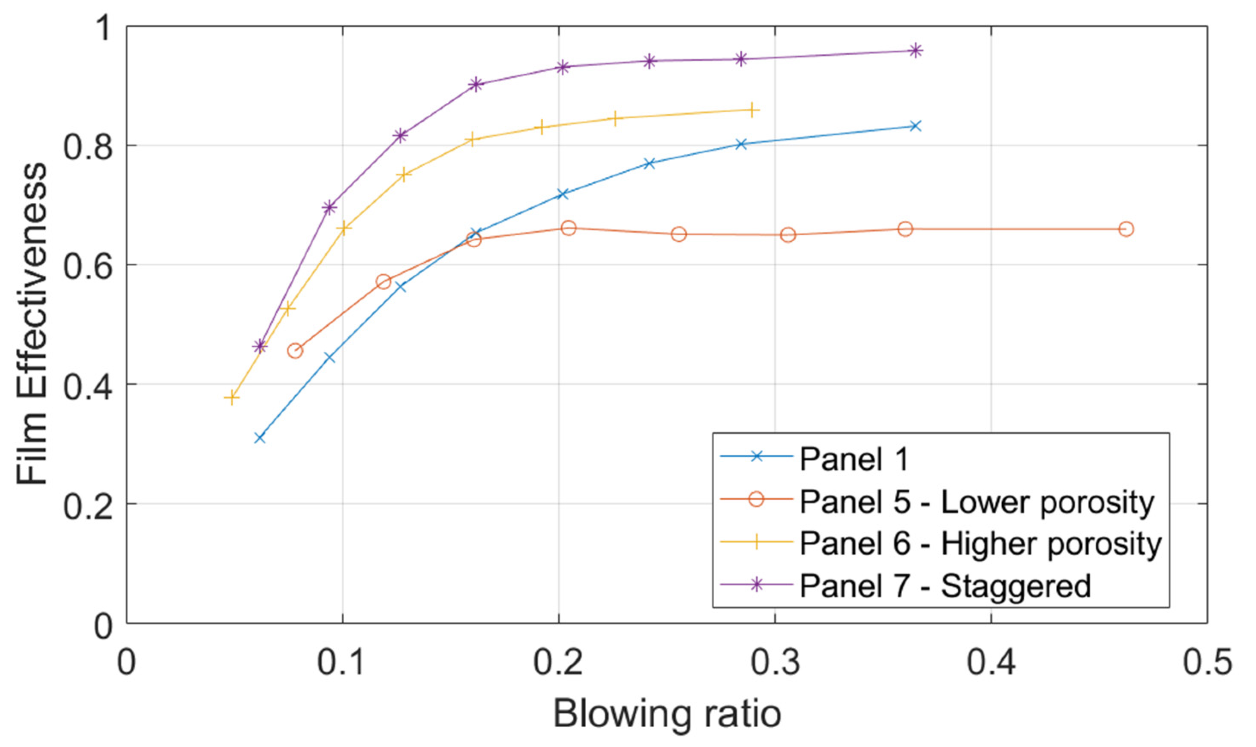
Figure 10 compares the film effectiveness of these panels at x/d = 75 against the calculated average blowing ratio of each panel.
A clear correlation between pitch and film effectiveness can be observed. While Panel 5 has a higher film effectiveness than Panel 1 at mean blowing ratios below 0.1 due to a better spanwise distribution, the maximum film effectiveness achieved does not exceed 0.65.
The effectiveness of all panels is observed to level off at a mean blowing ratio of approximately 0.2. This is significantly lower to most conventional film geometries, which tend to reach maximum effectiveness at a blowing of about 0.8. Additionally, this effectiveness does not drop back down as blowing ratio continues to increase indicating that, overall, film lift-off does not yet dominate the coolant flow.
While not necessarily lifting off, it still can be assumed that the films have reached a saturation point at higher mass flows and that additional coolant would not lead to an improvement in film effectiveness. Therefore the discriminating factor between Panels 1, 5, 6 and 7, is not the ability to add coolant to the boundary layer, but the ability to push the mainstream off of the blade surface. In conventional film theory, this would be equivalent to reducing the mass fraction of mainstream gas within the near wall boundary layer at the end of the panel.
The consequence of this is that instead of diluting the entrained hot air in the boundary layer with ever increasing mass flows of coolant, a high coolant to mainstream ratio can be achieved with much lower mass flows.
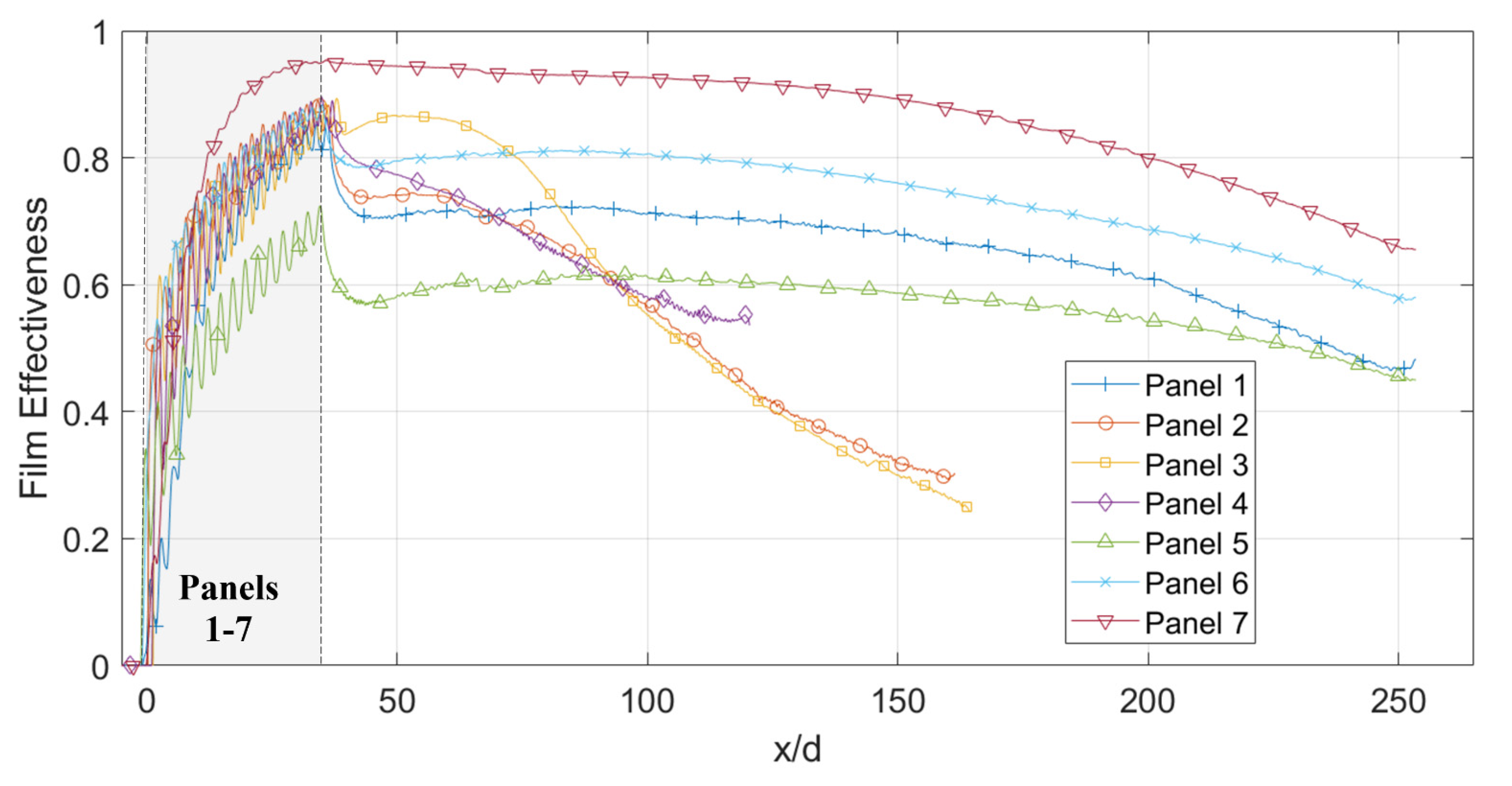
When comparing all of the different Panels at a mass flow for which the film is fully developed, further similarities and differences can be established. As shown by
Figure 11, all inline Panels with pitch to diameter ratios of 2.1 share approximately the same film effectiveness at x/d = 40. At this stage the film effectiveness is dominated by the Panels ability to add coolant to the boundary layer and fend off the mainstream gas. Once past this point, behavior becomes dominated by the particularities of the local mainstream flow such as the rate of boundary layer mixing and mainstream turbulence, with the film cooling geometry having only a minor effect due to the very low blowing ratios used. This is best exemplified by the near parallel behavior of Panels 1 and 5–7, showing that each is affected by the mainstream flow equally.
