Article

Effect of a Recirculating Type Casing Treatment on a Highly Loaded Axial Compressor Rotor

1
Japanese Acquisition Technology & Logistics Agency, Ministry of Defense, 1-2-10 Sakae-cho, Tachikawa-shi, Tokyo 190-8533, Japan
2
Department of Engineering, University of Leicester, Leicester LE1 7RH, UK
*
Author to whom correspondence should be addressed.
Int. J. Turbomach. Propuls. Power 2019, 4(1), 5; https://doi.org/10.3390/ijtpp4010005
Submission received: 9 August 2018 / Revised: 19 February 2019 / Accepted: 12 March 2019 / Published: 25 March 2019

Abstract

:
The tip leakage flow over the blades of an axial compressor rotor adversely affects the axial rotor efficiency and can determine the onset of tip leakage stall. The performance of a new casing treatment concept in the shape of an axisymmetric recirculation channel is explored by steady Reynolds-Averaged Navier–Stokes (RANS) realizable k-ε modelling on the NASA Rotor 37 test case. The modelling exposed a number of attractive features. The casing treatment increased the stall margin at no penalty to the rotor isentropic efficiency over the rotor operating line. A recirculation in the casing channel self-activated and self-adjusted with the rotor loading to provide more passive flow control at higher rotor loading conditions. The nozzle-shaped recirculation channel outflow opposed the tip leakage jet, re-located the casing surface flow interface further downstream, and reduced the rotor blade tip incidence angle. This combination of features makes the new casing treatment particularly attractive for applications to high thrust-to-weight ratio engines, typical of high-performance jet aircraft.

1. Introduction

Extending the envelope of stable operations allows designers to increase the Stall Margin (SM) between the normal operating line of the compressor and the compressor surge line. Alternatively, it allows operating the compressor at a higher pressure ratio without reducing the stall margin, to benefit the engine thermal cycle. There is, therefore, a significant amount of research and commercial interest in finding a way of widening the stable operating envelope of axial compressors that avoids introducing any isentropic efficiency penalty and that increases the compressor stage pressure rise. This paper reports seminal work on a rotor casing treatment with the potential of meeting these requirements. The potential outcome is a compressor capable of a higher stage pressure rise, resulting in a lower engine weight and in a lower engine cross-section.
Axial compressor stall and surge are established research topics among the aircraft engine community. Camp and Day [1] studied the axial compressor stall inception and identified the modal and spike stall inception modes through compressor rig experiments. Davis and Yao [2] provided an insight into the transient flow structure during the compressor stall inception by single/multi-passage time-resolved Reynolds-Averaged Navier–Stokes (RANS) simulations. Owczarek [3] pointed out how unsteady pressure pulses reflecting between the stator and the rotor blades affect the initiation of the rotating stall in axial compressors. Rotating stall onset is of greater concern in the presence of inflow distortion, which adversely affects high-spool speed and high-back pressure axial compressor operations [4]. Their numerical simulations showed that the inlet distortion had a stronger influence on the operation of the compressor stage under higher spool speed conditions and with higher back pressure conditions.
Mitigating the onset of stall is among the design requirements of axial compressors and modern aircraft engines use sweep and dihedral in three-dimensional blading to achieve this [5,6]. Vo [7] explored the alternative approach of active flow control by plasma actuators to extend the operating range of an axial compressor. His experiments with the low-speed axial compressor test rig and his numerical simulations on the same axial compressor showed that the actuators delayed the compressor stall inception by improving the flow structure near the compressor casing. Reutter et al. [8] investigated the effectiveness of a contoured end-wall design to suppress the blockage around the stator blade root. This specific end-wall contouring study was mainly aimed at improving the efficiency of the axial compressor and the contribution to improving the operational stability of the annular cascade by this approach was not discussed in depth.
Casing treatments have been investigated since at least 1971 [9] as an alternative or complementary approach to increasing the axial compressor stall margin; however, this approach is used less than three-dimensional blading. The casing treatments reported in previous studies can be broadly classified into two types, that is, non-axisymmetric slots and axisymmetric grooves.
The National Aeronautics and Space Administration (NASA) has shown that non-axisymmetric slots provide a significant enhancement in the stall margin but they were also found to penalize the compressor efficiency [9]. More advanced non-axisymmetric slot designs were investigated by Schnell et al. [10], who considered bend-skewed slots, and by Gourdain et al. [11], who evaluated axial slots with a curved roof through unsteady numerical simulations. Circumferential grooves provide lower gains in stall margin [9], but they do not show the compressor efficiency penalty of the non-axisymmetric slots. An axisymmetric groove is also simpler to manufacture. Currently, simple square grooves have been applied to the fan casing of the GE F110 turbofan engine [12].
Legras et al. [13] and Chen et al. [14] investigated the effect of multiple square grooves on the stable operating range of a transonic compressor through experiments and numerical simulations. Chen et al. [14] showed that the elimination of the reversed flow structure on the rotor tip correlated with the axial momentum delivered by the square grooves. Cevik et al. [15] studied circumferential grooves with a saw tooth shape. Houghton and Day [16,17], Sakuma et al. [18], and Mao et al. [19] investigated the influence of the position and size of a single square groove on the compressor performance. Sakuma et al. [18] found that a groove located at 0.2 axial chords from the leading edge of the blade was the best position for this design feature. Mao et al. [19] numerically showed that the circumferential groove also improves the operating range of an advanced counter-rotating axial flow compressor.
A further type of casing treatment is one that uses a recirculating channel. Koff et al. [20] used a channel in the casing wall with airfoils that aimed at reducing the tangential velocity component of the flow through it. Hathaway [21] modelled the flow through an axial compressor with a recirculating type casing treatment by solving the one-dimensional mass balance equations between the channel inlet and outlet. Their application to a NASA axial rotor indicates that this treatment extends the rotor operating range without producing an adiabatic efficiency drop. More recently, Dinh et al. [22] conducted a parametric study on the design of a recirculating type casing treatment. They varied the injection positions, the bleed position, and the width of the channel to evaluate their influence on the compressor performance and managed to identify a useful range of parameters for which the rotor is able to operate at lower mass flow rate conditions. Applying the recirculating type casing treatment is also expected to improve the performance of centrifugal compressors. Yang et al. [23] examined the effectiveness of the recirculating type casing treatment in a high-pressure ratio centrifugal compressor. The experiments showed a large improvement of the operating range at more than 0.9 design rotational speed conditions by the application of the casing treatment.
These feasibility studies on the recirculating type treatment show good promise; however, a more extensive concept validation in a multi-row axial compressor configuration is required.
Despite this scientific endeavor in evaluating casing treatments, two aspects appear to deter their widespread adoption in axial compressor designs. These are the concerns regarding having to compromise between stall margin and component efficiency, and engine weight increases from a thicker casing, both aspects affecting the engine fuel consumption. There appears to be a significant opportunity for a breakthrough design able to address both concerns. The potential impact of such a design, if adopted industry-wide, is high. The aim of this paper is to explore this by studying the flow of the passive control design shown in Section 2. This concept is explored by a numerical modelling approach described in Section 3. The simulation of a conventional square groove casing treatment is also carried out for comparison purposes. Section 4 validates a numerical model of the NASA Rotor 37 that is used in Section 5 for testing numerically the casing design of Section 2. In Section 6, conclusions are presented on whether the new concept indeed delivers a significant gain in the stall margin without compromising the compressor stage isentropic efficiency with a simple, manufacturable, light-weight geometry.

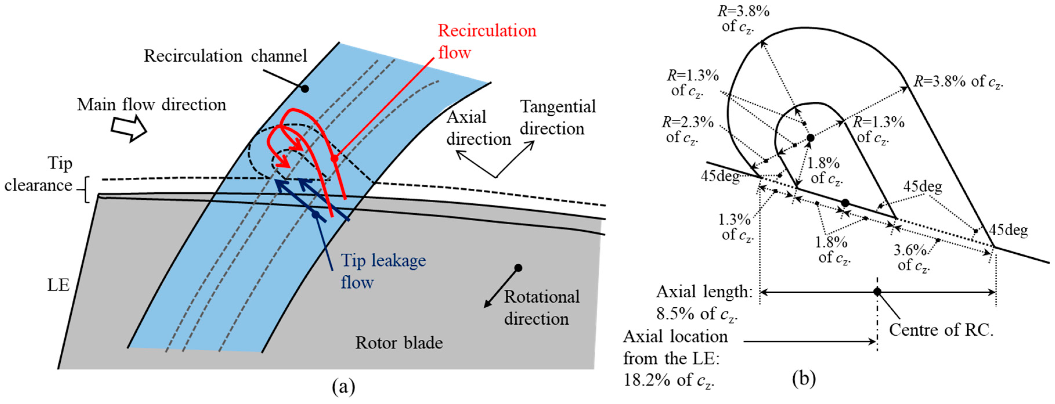
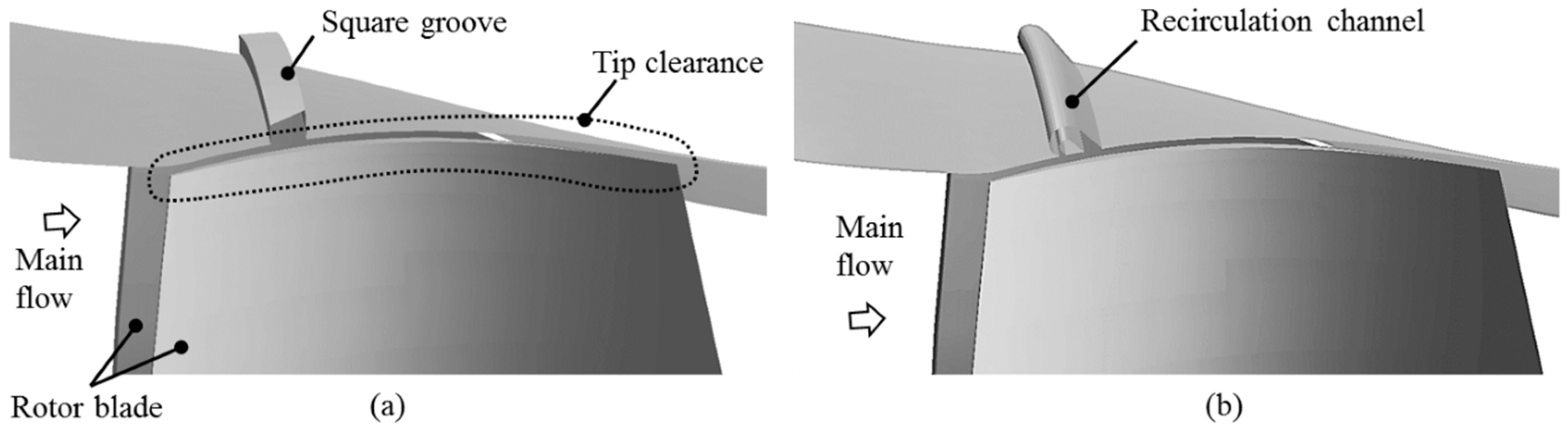
2. Axisymmetric Recirculation Channel Design for Axial Rotors

Rotor blades and axial flow compressors can feature a rotor tip type stall, by which reverse flow at the rotor tip progressively extends over the blade span. Rotor tip leakage promotes the onset of this reverse flow, as explained in Section 4. By controlling the rotor tip leakage, a delay in the tip stall onset is sought. Figure 1 describes the concept of a self-adjusting passive control technique for the rotor tip leakage. An axisymmetric channel was designed on the casing wall over the rotor blade. The size of the Recirculation Channel (RC) was small compared to the rotor blade, and the axial length of the RC was only 8.5% of the rotor blade tip axial chord cz as shown in Figure 1. This channel design broadly draws from a detail of a one-way valve by Nikola Tesla [24]. The angles of suction and of injection to the casing flow were set at 45°. A recirculating flow was induced in this RC by the pressure difference between the suction side and the pressure side of a rotor blade. This pressure difference was enhanced by the axial pressure gradient through the rotor passage. The induced flow was intended to seal the tip leakage flow near the casing wall. The channel outlet was of a subsonic nozzle shape to obtain a high momentum with a small recirculation mass flow rate. The axial component of this high momentum flow was in the positive axial direction. This was opposite to the axial velocity of the leakage flow. The high momentum flow therefore opposed the motion of the leakage flow. This leakage flow mitigation approach did not require reducing the rotor tip clearance. Therefore, this design was less likely to suffer from blade tip rubbing issues than more established flow resistive type approaches, such as labyrinth seals, which rely on small tip clearances. This recirculation channel design does not exclude in principle the use of abradable coatings on the casing surface.
A concept level assessment was performed on the manufacturability of the design of Figure 1b. In principle, the channel can be manufactured by investment casting, using a ceramic boss that is chemically removed after solidification. At least one alternative manufacturing technique is available, due to the good clearance between the inner and outer channel walls, by which the inner channel wall boss can be cast separately, either as a single piece or in azimuthal segments, and then slotted in place or assembled as required. The inner channel wall forms an axisymmetric boss, or ring, which requires at least three supporting struts in the azimuthal direction to be secured. The comparatively small azimuthal cross-section of the struts compared to the ring warrants not including this feature in the current study. The radii and angles reported in Figure 1 have been considered for manufacturability and none appear to be either too small or too sharp from a manufacturing prospective.

3. Numerical Approach for Validating the Design

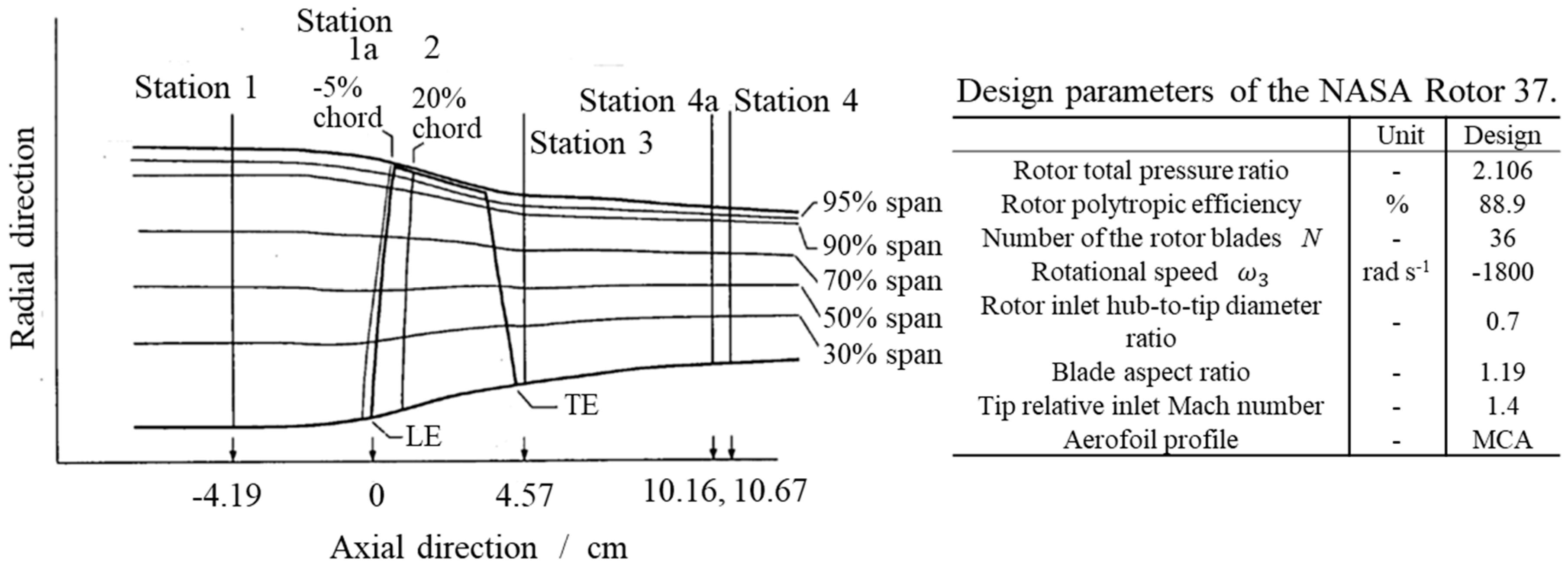
3.1. Axial Compressor Test Case

The NASA Rotor 37 [25,26] was used to validate the concept of the recirculation channel casing design. A meridional plane sketch of the NASA Rotor 37 is shown in Figure 2 and summarizes its main design parameters. This axial compressor rotor was designed by NASA as the first stage rotor of a core engine compressor and was tested experimentally at the NASA Glenn Research Center (formerly known as the NASA Lewis Research Center). Details of the compressor geometry and of the experimental measurements are provided in the literature [25,26,27]. Although many contributions to the aircraft propulsion research literature have used the NASA Rotor 37 as a test case, it is considered that several flow features are still not entirely explained. As the stage design total pressure ratio of 2.1 is relatively high compared to current axial compressors, this compressor geometry is representative of highly loaded compressors, such as the ones used in high-specific thrust engines of high-speed aircraft.
Figure 3 shows one flow passage of the NASA Rotor 37, rendered in three dimensions. The casing includes two treatments that are absent in the original geometry. The treatment in Figure 3a is a simple square groove used in previous work and the treatment in Figure 3b is that of the recirculation channel from the previous section. In this work, a circumferential square groove was selected as the reference casing treatment case because it is able to avoid the addition of unwanted adiabatic efficiency penalties by its application [9]. Both casing treatments were applied at approximately 20% axial chords downstream from the blade leading edge in the axial direction, since in Reference [18] this gave the best stall margin among the investigated axial locations. The height of the rotor blade tip clearance was set to 0.356 mm in all cases.

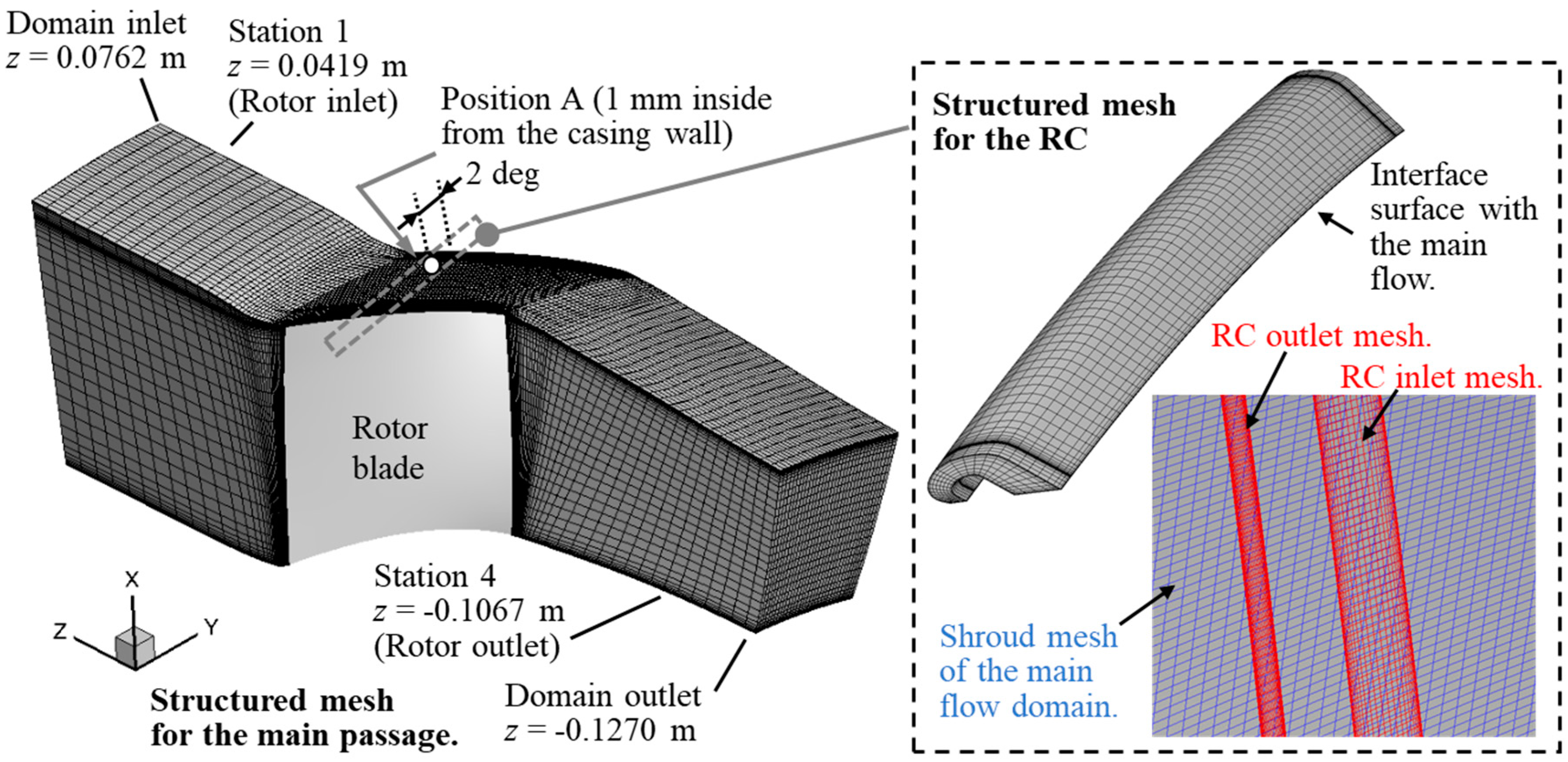
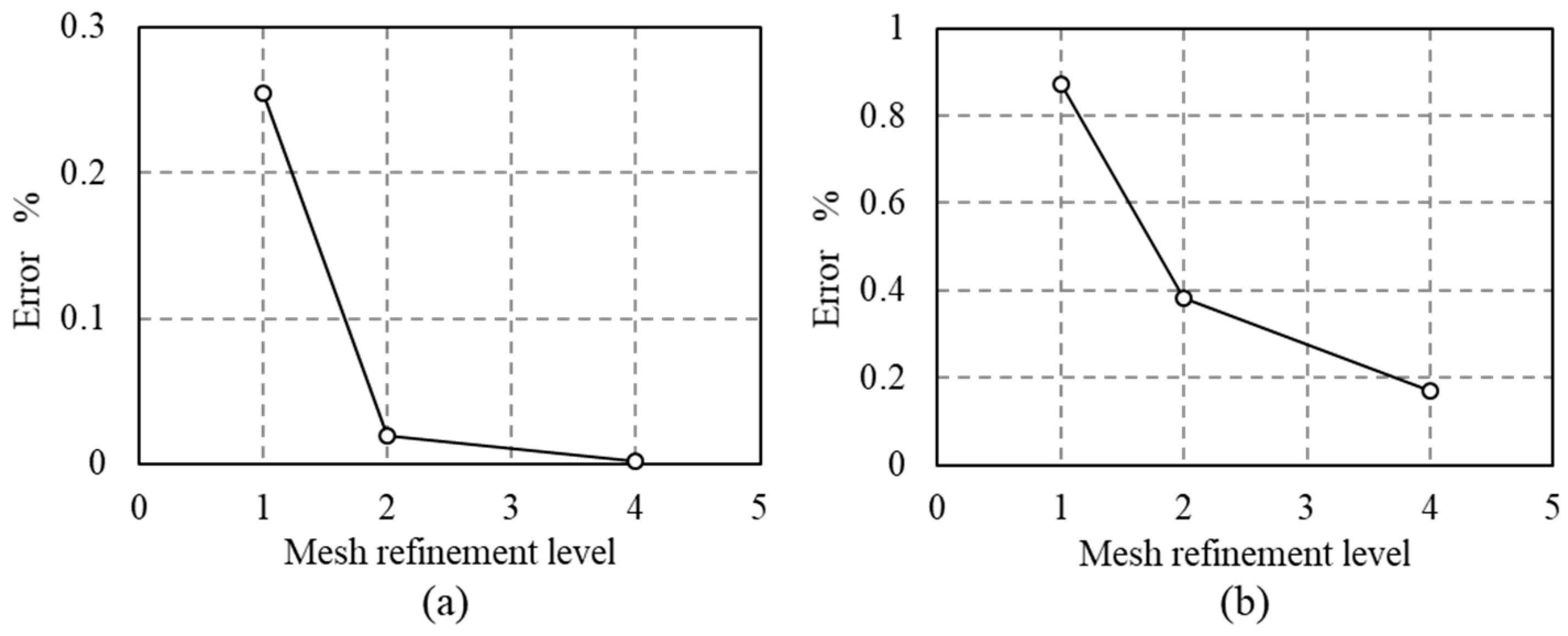
3.2. Computational Grid

The flow through one passage of the NASA stage 37 rotor row was modelled by the computational domain and mesh shown in Figure 4. ANSYS ICEM CFD (ANSYS Inc., Canonsburg, PA, USA) was used for generating a structured computational mesh. In Figure 4, the mesh is shown coarsened by a factor of two in each spatial direction, for graphical rendering purposes. Only one blade-to-blade passage was modelled for limiting the cost of the computation. This configuration corresponded to 1/36th of the rotor full annulus. A 5 × 10⁻⁶ m constant height for the first cell normal-to-solid surfaces was used throughout the domain, which achieved an average near-wall resolution of y+ ≈ 1.5. To estimate the error caused by the spatial discretization on the flow predictions, a mesh convergence study was carried out using Richardson’s extrapolation that was generalized by Roache [28]. Figure 5 summarizes the result of the grid convergence study. In this work, three meshes were used to discretize the rotor passage with a constant refinement ratio rm = 2.0. These were a coarse mesh of 0.7 M nodes (mesh A), a mesh of intermediate spatial refinement of 1.5 M nodes (mesh B), and a fine mesh of 3.1 M nodes (mesh C). In the present work, two grid convergence indexes (GCI) were calculated. These meshes did not include the recirculation channel domain. The first GCI was calculated based on the adiabatic efficiency of the rotor blade row and the second GCI was based on the local value of the static pressure near the rotor pressure side tip at the near-stall (NS) operating condition. The location of the local static pressure monitor was denoted as Position A in Figure 4. Position A sits directly under the recirculation channel inlet shown in Figure 3, and it is where Section 5.2 reports the breakdown of the tip leakage vortex, which is identified as the main driver of the stall inception in this rotor. The difference between the adiabatic efficiency ηn predicted using the nth mesh and the one obtained from Richardson’s extrapolation ηR was used to define the relative error as e = η n η R 1 1 . Based on this, the magnitude of the adiabatic efficiency error for mesh B was estimated to be 0.020%. The GCI computed from the local static pressure at Position A in Figure 4 predicted with the mesh A and that with the mesh B was higher than the GCI computed from the local static pressure at the position A predicted with the intermediate mesh (mesh B) and that with the fine mesh (mesh C). The estimated magnitude of the local static pressure error for the mesh B was 0.383%, which was sufficiently small for the purpose of this study. Specifically, this study used computational fluid dynamics to estimate the performance changes from variances of the compressor passage geometry as opposed to absolute performance values. This allows to accept the stated small GCI errors and to use the refinement level of the intermediate mesh (mesh B) for the remainder of this study.
The structured mesh for the recirculation channel was first created as a stand-alone mesh and then it was abutted to the main passage mesh by defining the interface between the two. Along the common boundary between the two meshes, the abutting meshes were non-conformal. Therefore, the flow properties were interchanged between the two domains by a Gaussian-gradient-based spatial interpolation. Figure 4 shows an enlarged view of the interface between the RC and the main flow path. The number of nodes generated for the recirculation channel domain shown in Figure 4 was 0.2 M.

3.3. Numerical Modeling

The calculations were run as steady and time-resolved RANS simulations with the realizable k-ε turbulence closure model [29]. ANSYS Fluent was used as the flow solver. Table 1 shows the flow conditions used in this simulation. The working fluid was dry air, with constant specific heats, modelled under ideal gas assumptions. The flow governing equations were the compressible Reynolds-Averaged Navier–Stokes equations for viscous fluids.
In this study, the specific heat at constant pressure cp was set to 1004 J kg−1 K−1 [26]. The thermal conductivity κ was calculated by kinetic theory [30]. The air viscosity was estimated by Sutherland’s law.
The Roe flux difference split method was used, in combination with the Roe approximate Riemann solver [31], to estimate the convective fluxes at the finite-volume unit cell boundaries throughout the computational domain. The flow state inside each unit cell was reconstructed using a third-order Monotone Upwind Scheme for Conservation Laws (MUSCL) from Roe [31]. The implicit integration method by Weiss et al. [32] iterates the numerical solution to a converged steady state. Pseudo-time advancement was performed by local time-stepping with the Courant number limited to 5. An under-relaxation factor of 0.8 was used for the specific turbulent kinetic energy k and for the specific dissipation rate of specific turbulent kinetic energy ε to improve the numerical stability of the computation. At the computational domain inlet, an axially uniform inflow was imposed based on the inflow stagnation pressure and on the inflow stagnation temperature reported in Table 1. The inflow was turbulent and uniform inflow k and ε fields were prescribed based on the turbulence intensity and on the turbulent length scale values of Table 1. At the computational domain outlet of Figure 4, the static pressure was imposed under the condition of radial equilibrium and all other variables were extrapolated from the computational domain interior.
For time-dependent RANS, a macroscopic pressure resistance model defined in Equation (1) was applied at the outlet boundary in order to model the pressure drop during the stall inception process.
P o u t = 101.325 + 1 2 c t ρ ¯ u ¯ a 2 1000
In Equation (1), ct is the pressure resistance coefficient of the downstream throttle valve which was used in the experiment to set the operating condition of the compressor rotor, ρ ¯ is the mass-averaged fluid density at the computational domain outlet, and u ¯ a is the mass-averaged axial velocity at the computational domain outlet. All other variables were extrapolated from the computational domain interior.
At all solid boundaries, no-slip adiabatic conditions were used. At the pitch-wise boundaries, pitch-wise periodic conditions were imposed based on the one-pitch rotational periodicity of the fan blade row. Steady RANS convergence was deemed to be achieved when the change in the mass flow rate was 0.001% of the inflow. This was achieved by performing between 10,000 and 30,000 iterations, depending on the rotor back pressure. The simulations were conducted on the University of Leicester (Leicester, UK) high-performance computing cluster ALICE, which had 4760 Intel 2.4 GHz cores (Intel Corporation, Santa Clara, CA, USA). Parallelization was achieved by domain decomposition using the METIS algorithm in ANSYS Fluent for partitioning the computational mesh in 16 zones. The computation used 16 strands distributed across up to 16 cores. The wall time required for the calculation of 5000 iterations was 2.0 h.

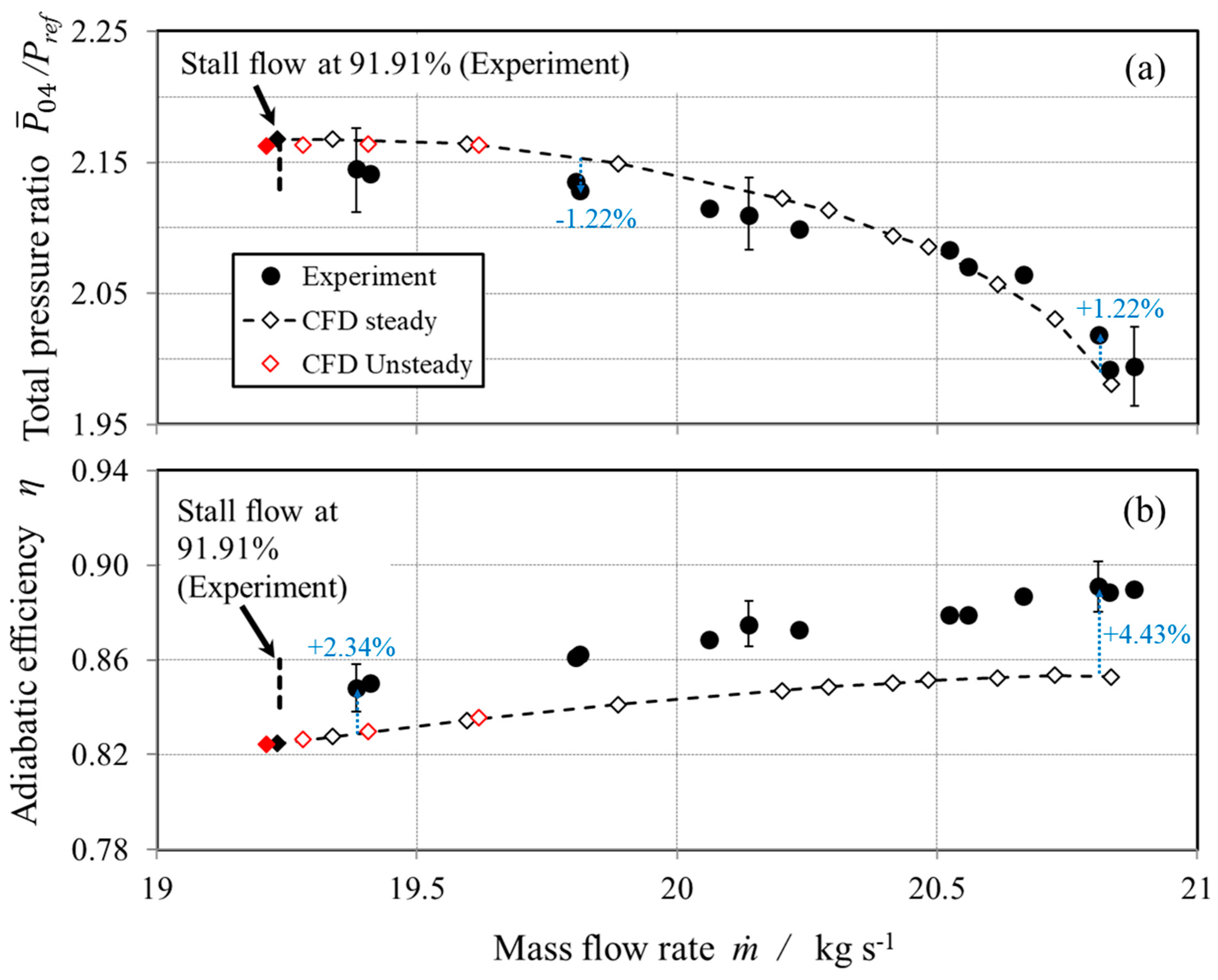
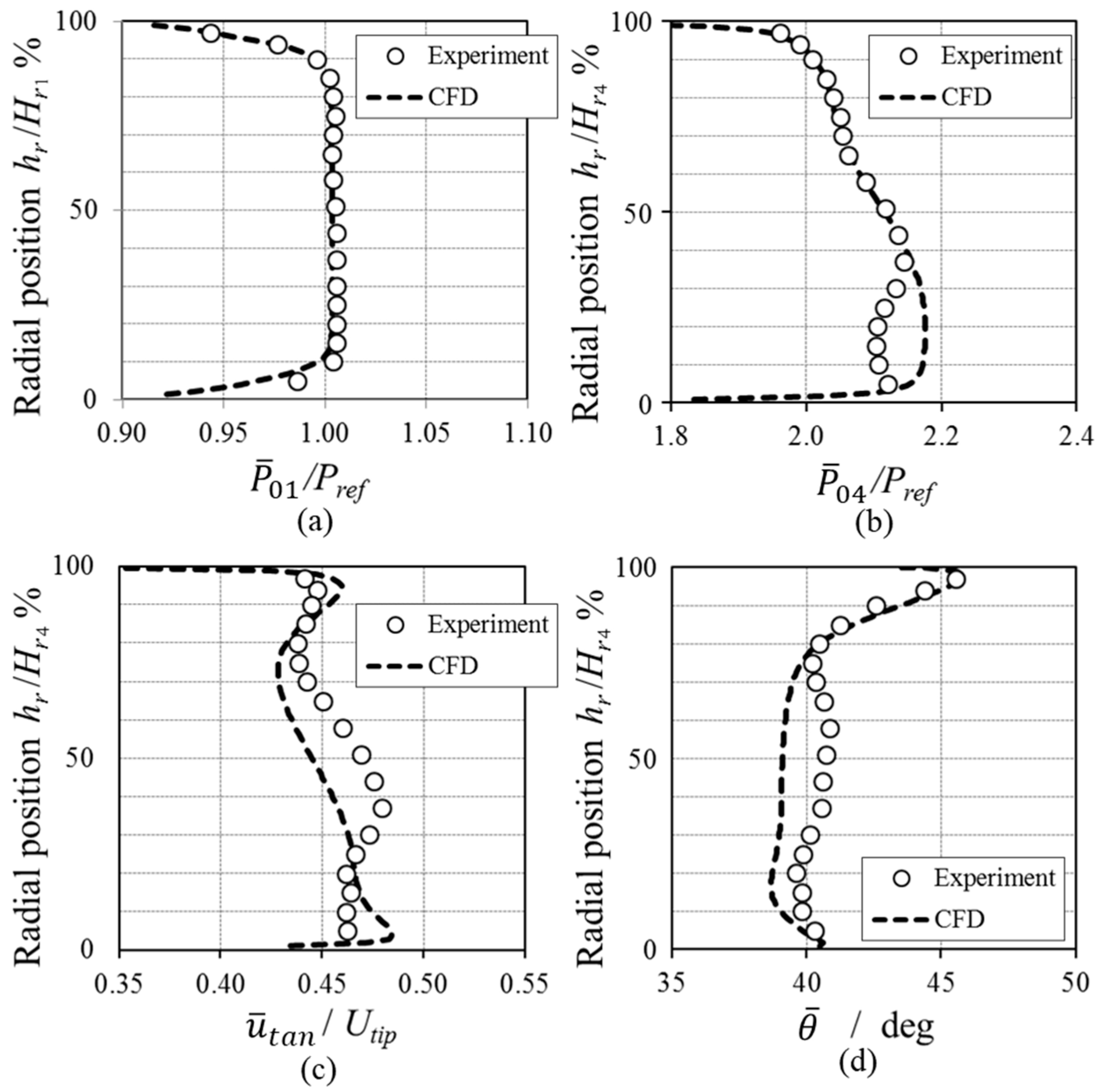
4. Validation of the Numerical Model

Figure 6 shows the NASA Rotor 37 performance predicted by the current numerical model compared to reference measurements and numerical predictions from the literature. Table 2 compares the choked mass flow rate and the normalized mass flow rate at near-stall condition between Computational Fluid Dynamics (CFD) and experiment. The procedure for identifying the NASA Rotor 37 operating limits was the same as in [33]. The predicted choked mass flow rate was 20.84 kg/s, which is within the measurement uncertainties (±0.3 kg s−1) given in [34] of the corresponding experimental value. The operating condition that had the lowest mass flow rate among the numerically converged simulations was defined as the operating limit of this rotor. This was identified by running simulations with progressively higher values of back pressure Pout. The final increment of the back pressure to detect the stall inception was fixed to 0.3% of the atmospheric pressure in all the calculations shown this paper. Although the current numerical model overestimates the total pressure ratio at low-mass flow rate conditions, the predicted total pressure characteristic shows a good agreement with the experimental data, as the trend line of the predictions lies within the measurement uncertainty of the experimental data. The shape of the adiabatic efficiency curve was overall well predicted; however, the predicted rotor adiabatic efficiency was about two percent lower than that measured in the experiments. This underestimation of adiabatic efficiency is a known feature of numerical analyses of the NASA Rotor 37, as reported in [33]. As pointed out by Denton [33], the difference in the procedure of mass-averaging on the measurement plane may cause this systematic underestimation of the adiabatic efficiency.
The current numerical model predicts the near-stall condition at m ˙ N S = 19.23 kg s−1, which is slightly lower than that reported in the experiment, without any casing treatment. As shown in Table 2, the choked mass flow rate and the mass flow rate at the near-stall condition predicted by the current numerical simulations lie within the spreads of the predictions from the literature. The numerical simulations show disparities of ±1.22% in total pressure ratio and show disparities between 2.34% and 4.43% in adiabatic efficiency against the experimental results.
Figure 7 compares the radial profiles of mass-averaged pressure, velocity, and flow angle at Station 4 of Figure 4 between the CFD and the experiment. These profiles are in good agreement with the experimental results, shown by the symbols. The results shown in Figure 6, Figure 7, and Table 2 indicate that the current steady RANS simulation with the realizable k-ε turbulence model was capable of evaluating the performance of the NASA Rotor 37 for the purpose of assessing different casing treatments.

5. Results and Discussions

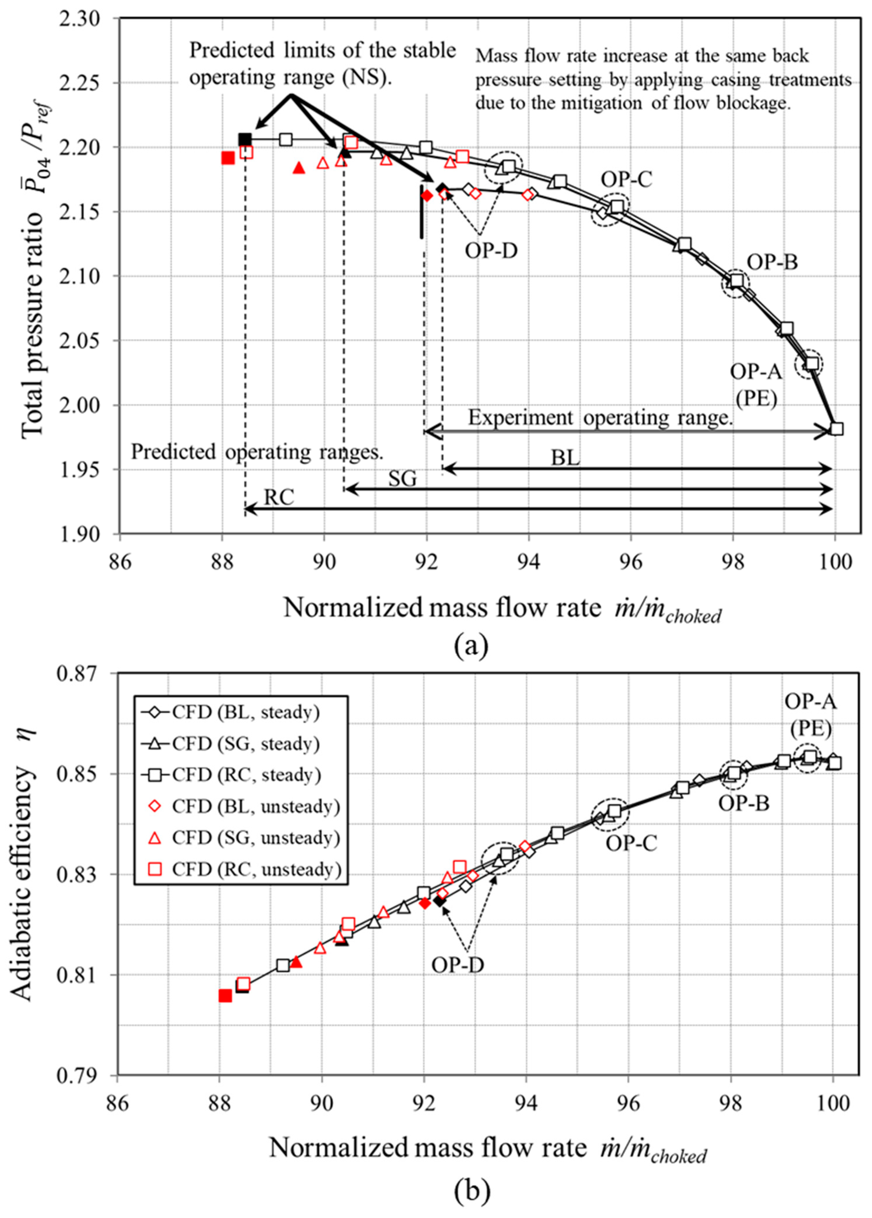
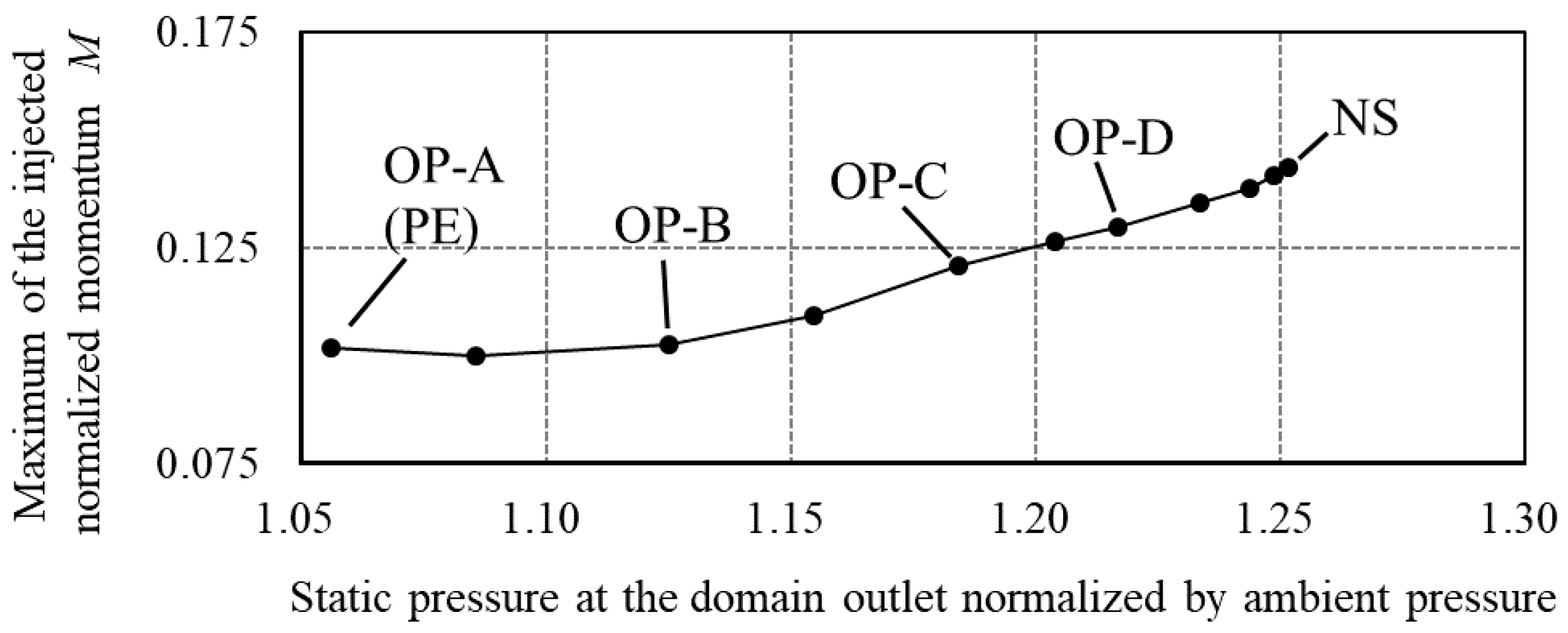
5.1. Overall Compressor Performance Characteristics

Figure 8 compares the compressor performance characteristics with and without the casing treatments of Section 2. Five different operating conditions are identified, labelled OP-A to NS. These range from the Peak Efficiency (PE) regime at OP-A, to the stall limit of the baseline case (OP-D), to the Near Stall (NS) condition of the cases with casing treatment. Time-resolved RANS calculations were conducted at near stall operating conditions in order to improve confidence in the results reported with steady RANS simulations. The choked mass flow rate m ˙ c h o k e d of the Baseline (BL) case, with no casing treatment, was used to normalize the abscissa. By applying the casing treatments, the mass flow rate at OP-D increased, due to the reduction in the flow blockage through the main passage near the casing, as shown in Figure 9. The overall performance of each configuration obtained by steady RANS simulations is summarized in Table 3. The operating points predicted by the transient analysis follow the operating line predicted by the steady RANS simulations. The operating ranges obtained by unsteady RANS simulations tend to be larger than those obtained by steady RANS simulations. The stall margin (SM) was calculated by Equation (2) overleaf, as used in [18] and [37]. The adiabatic efficiency η was calculated by Equation (3). The SM increment predicted by the square groove (SG) CFD test case was within the range of 1.9% to 3.7% as reported in [18]. By the application of the recirculation channel (RC), the operating range was extended to 86.8% of m ˙ c h o k e d . The extension of the SM was approximately 5% with respect to the baseline case (BL) and it is shown in Figure 8a to be greater than that obtained by using the square groove (SG) casing treatment.
Past work on the development of effective casing treatments for extending the stall margin of axial compressors reported component efficiency penalties associated with this approach [16]. Figure 8b is very encouraging as it shows that the casing treatments considered herein are predicted to have a small positive effect on the rotor adiabatic efficiency. Hathaway [21] applied a recirculating casing treatment to Rotor 67 and showed a larger stall margin improvement than this study. Since the casing treatment applied in [21] was longer in the axial direction than in the current study, it is thought that a larger pressure difference between the channel inlet and the channel outlet was obtained in [21], which may explain the larger improvement in the compressor stall margin reported in [21].
BL: Baseline casing; SG: Casing with Square Groove [12]; RC: Casing with Recirculation Channel.
SM = [ 1 m ˙ N S · ( P ¯ 04 / P ¯ 01 ) P E m ˙ P E · ( P ¯ 04 / P ¯ 01 ) N S ] × 100 ,
η = [ ( P ¯ 04 / P ¯ 01 ) ( γ 1 ) / γ 1 T ¯ 04 / T ¯ 01 1 ] × 100 .

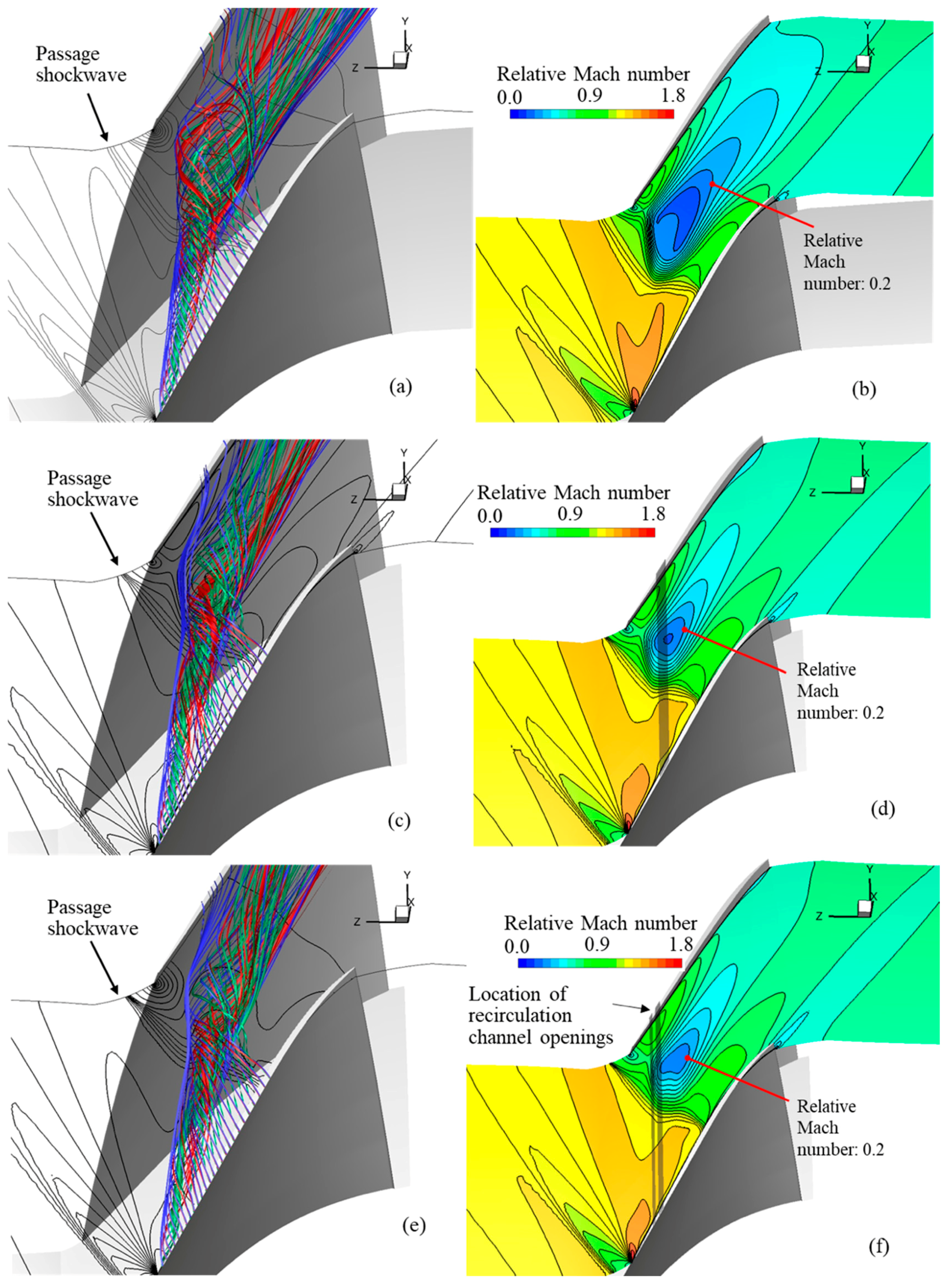
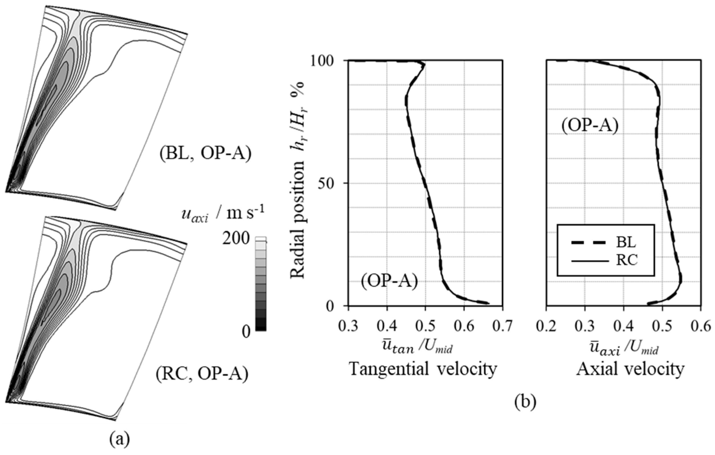
5.2. Analysis of the Passage Flow Structures

It is of interest to examine the flow structure through the rotor with and without the casing treatments to gain an insight on how the recirculation channel design can deliver the stall margin gains without showing any adiabatic efficiency drop, as reported in the previous section. Figure 9 gives an annotated comparison of the passage flow structure near the casing, without casing treatment, in Figure 9a,b, with the square groove treatment, in Figure 9c,d, and with the recirculation channel treatment, in Figure 9e,f. The streamlines are traced from the same seeds placed inside the tip clearance. These streamlines are colored by the height of the seeds. The blue, red, and green streamlines were generated from seeds placed at 85%, 50%, and 15% tip clearance height, respectively. Figure 9a,c shows that the tip leakage flow feeds a longitudinal vortex, which is often referred to as the tip leakage vortex. The color code of the seeds shows that the leakage flow at a 15% and 50% tip clearance height mostly forms the vortex core. The blue streamlines in Figure 9a,c,e circulate mostly outside of this longitudinal vortex and pass near the pressure side of the adjacent blade. The tangling of the strands of different colors displays the radial mixing action by the tip leakage vortex. The tip leakage vortex is shown in Figure 9a to break down in the middle of the passage, where it crosses the passage shockwave. The passage shockwave is indicated by a cluster of static pressure contours in Figure 9a,c that stems from the blade leading edge. Upon breaking down, the tip leakage vortex generates a low velocity region, as indicated by localized relative Mach number minima located mid-way pitch-wise between the two blades. This low-velocity region effectively creates a passage blockage between the rotor blades and it is an unwanted feature. By the application of the recirculation channel treatment, Figure 9f shows that the size of this low-velocity region near the casing was visibly reduced. The volume where the relative Mach number equals 0.2 or less was reduced to about 1/11th of the corresponding BL case volume, by adding the RC to the compressor casing.
As mentioned in the discussion of Figure 8 and reported in Figure 3, the recirculation channel casing treatment simulation showed a slight increase tendency in the component adiabatic efficiency. Since the recirculation channel mitigates the blockage near the casing wall, this effect is consistent with this improvement in the rotor adiabatic efficiency.
Figure 10 shows the comparison of the flow angle distributions around the rotor leading edge (LE), near the casing, with and without the casing treatments. The locations of the channel inlet and of the channel outlet are highlighted by blue rectangles in Figure 10c,d. The blockage associated with the vortex breakdown is shown to the right of the rotor blade leading edge as a high-flow angle region. The main passage flow tries to find a way around this blockage by deviating towards the blade suction side (SS). This leads to a high-flow angle over the blade leading edge in Figure 10a. The high incidence in combination with the tip leakage flow causes a rotor tip leading edge flow separation over the rotor blade SS, as shown in Figure 10a. By adding the recirculation channel casing treatment, the blockage reduces and relocates to the axial position of the casing treatment. The reduced blockage decreases the leading edge flow angle and mitigates the high-angle flow responsible for the separation in the neighboring passage, as highlighted by red lines of θ = 110 degrees in Figure 10c. Figure 10d shows that the recirculation channel retains its effectiveness at mitigating the flow blockage at the NS conditions.
By reducing the flow separation through this mechanism, the radial profiles of axial velocity downstream of the recirculation channel outlet in Figure 11 show important changes near the casing. The negative uaxi/Umid denotes axial velocity directed upstream. Near the casing, the dashed lines in Figure 11 show reversed flow in the simulation without the casing treatment. By adding the RC casing treatment, the magnitude and the extent of the reversed flow were significantly reduced at the operating conditions OP-A and OP-D, as shown by the continuous line. This improved the main passage flow close to the casing, over the top 0.3% to 0.4% of the blade span. The axial velocity profile over the remainder of the span appeared to be substantially unchanged. The recirculation channel casing treatment enabled operating the rotor at a higher back pressure and at a lower mass flow rate than the baseline (BL) geometry without the casing treatment, as shown in Figure 3a. Figure 11 shows reversed flow near the casing at this increased back pressure condition. No dashed-line velocity profile is shown at the NS condition in Figure 11 for the baseline and for the square groove simulations as, at this condition, the rotor is stalled.
It is of interest to study the effect of the casing treatment on the rotor outflow, with the aim of investigating whether this outflow would have any negative effect on the operation of any stator blade row that may be downstream of it. For this purpose, Figure 12a shows the velocity distributions at the axial plane 1 mm downstream from the rotor blade row exit axial plane. The distribution of axial velocity at the peak efficiency condition OP-A indicates that the influence of the RC on the exit flow was negligible. This is confirmed by Figure 12b, which shows the circumferentially averaged profiles of tangential velocity and of axial velocity at the same test plane. Along the blade span, the changes in normalized u = t a n and u = a x i were small between the BL case and the RC case. This was because the recirculation channel applied in this study only affected the near-casing flow and left the remainder of the velocity profile substantially unchanged. Furthermore, the injection was not intense away from flow stall, at the operating condition (PE), at which the typical engine operating line is set [38]. Specifically, the normalized momentum injected in the axial direction M was 0.102 at the OP-A (PE) condition, as reported in Section 5.3.

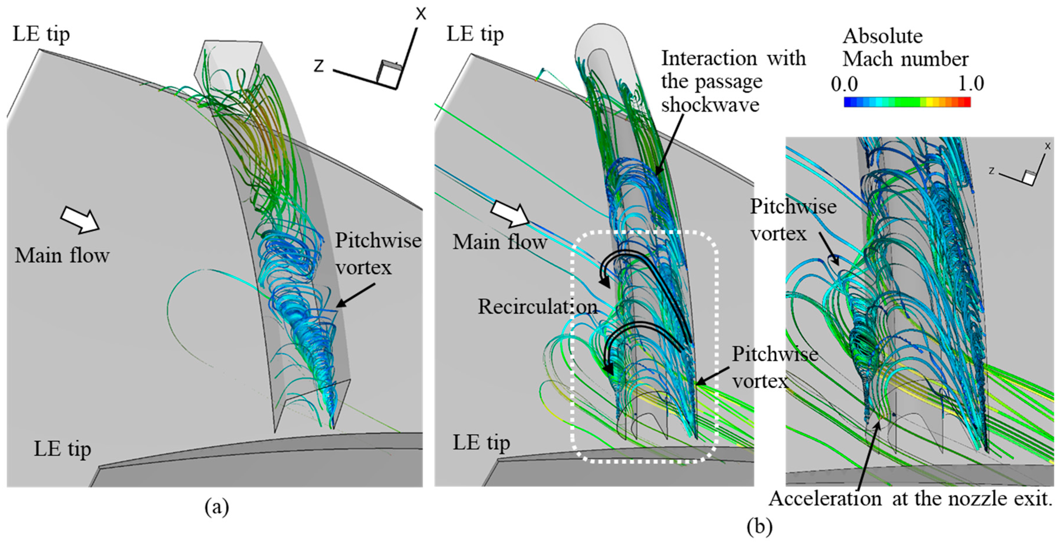
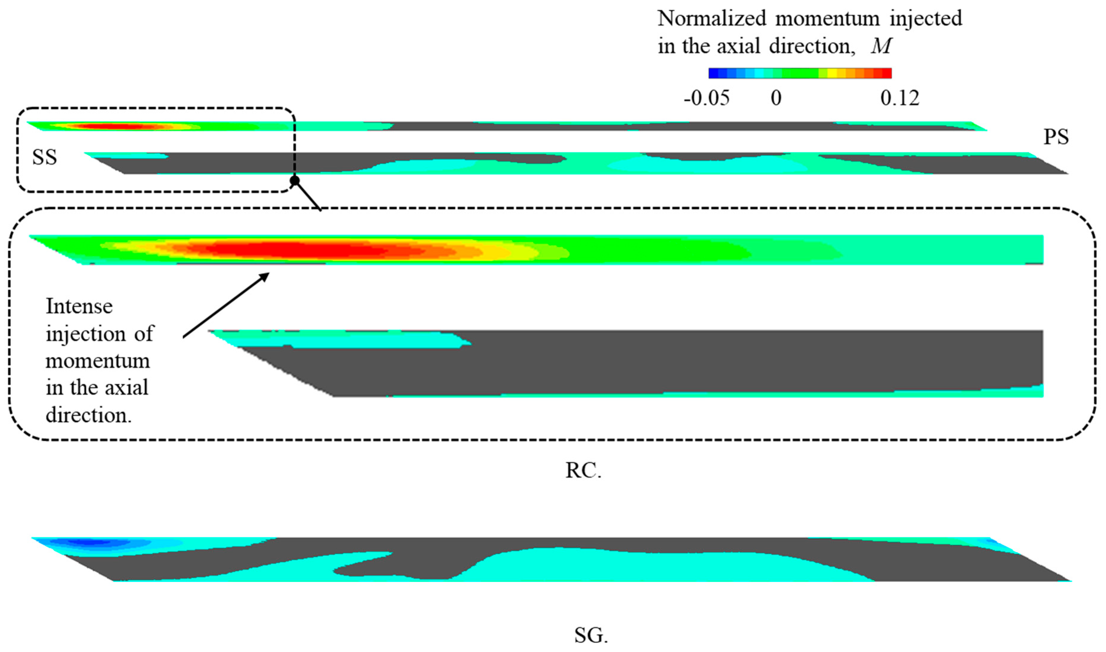
5.3. Flow Structure Inside the Casing Treatments

Figure 13 shows the flow structure through the square groove and through the recirculation channel casing treatments, by streamlines of absolute velocity. The sharp edge between the square groove and the casing is shown in Figure 13a to trip the inflow into the groove, which spins a pitch-wise vortex. The same flow feature was reported in Reference [18]. The pitch-wise growth of this vortex, upon approaching the neighboring blade at the top of Figure 13a, may provide a sealing effect for the tip leakage. The flow structure obtained through the recirculation channel of Figure 13b was instead quite different. Above the tip of the rotor, the flow was induced into the channel from right to left, as indicated by the black arrows. The axial flow velocity through the channel had the opposite direction to that of the main flow, which is shown by the large white arrow in Figure 13b. This motion is referred to as a recirculation. The channel outlet (left hand side opening) had a reducing radial cross-section that acted like a nozzle, which accelerated the channel outflow, as indicated by the green–yellow color of the streamlines at this location. The simulations indicated that most of the recirculation occurred above the passing rotor blade. About 40% of the pitch from the blade SS was affected by flow injection from the RC. Further away pitch-wise from the blade tip suction side, the streamlines were shown to no longer be going from the channel inlet to the channel outlet, in correspondence to the pitch-wise location of the passage shockwave shown in Figure 9c. This was actually a positive feature of this axisymmetric casing treatment, as it provided the controlling flow just over a passing rotor blade to control locally the tip leakage flow, and allowed the main passage flow to flow through unobstructed.
Figure 14 shows the distribution of the normalized axial momentum at the recirculation channel inlet and outlet. The normalized momentum was calculated as M = ρ u r a d u a x i / ρ r e f ( U m i d ) 2 , where ρ r e f was the inlet ambient condition and U m i d was the blade mid-span velocity. The portion of the channel inlet and outlet where u r a d was negative and the flow injected into the main passage was contoured by levels of M. Areas where u r a d was positive and the flow moved from the main passage into the casing recess are shown by a uniform grey tone. Flow injection into the main passage mitigated the tip leakage flow by the mechanism described in Section 5.5. Areas where u r a d was positive cannot provide mitigation by the same mechanism, therefore they have no obvious role to play in controlling the tip leakage flow. For comparison purposes, the equivalent results from the square groove casing treatment are presented in the same figure, showing the surface where the groove opens into the rotor main passage. Compared to the square groove case, far more axial momentum was added at the channel outlet near the blade SS by using a recirculation channel, as highlighted by the magnified detail of the recirculation channel inlet and outlet in Figure 14. This result reinforces the evidence of the recirculation channel being a self-activating passive flow control system for rotor tip leakage.
Figure 15 illustrates how the maximum normalized axial momentum injected into the main passage by the recirculation channel changes with the compressor loading. At low-loading conditions, including at the peak efficiency (PE) operating point, the injected maximum normalized axial momentum was nearly constant, with value of 0.102. After passing the OP-B, the injected momentum increased monotonically up to the stall inception. This feature shows an interesting and welcome self-regulating property of the recirculation channel treatment. This treatment increases the axial momentum that opposes the tip leakage flow at higher loading conditions, where stronger reverse flow occurs in the baseline configuration, as shown in Figure 11. The recirculation channel treatment is, therefore, both self-activating and self-adjusting, providing an appropriate passive flow control. No active (actuator/sensor) external control is required to adjust the injection to changes in the rotor loading.

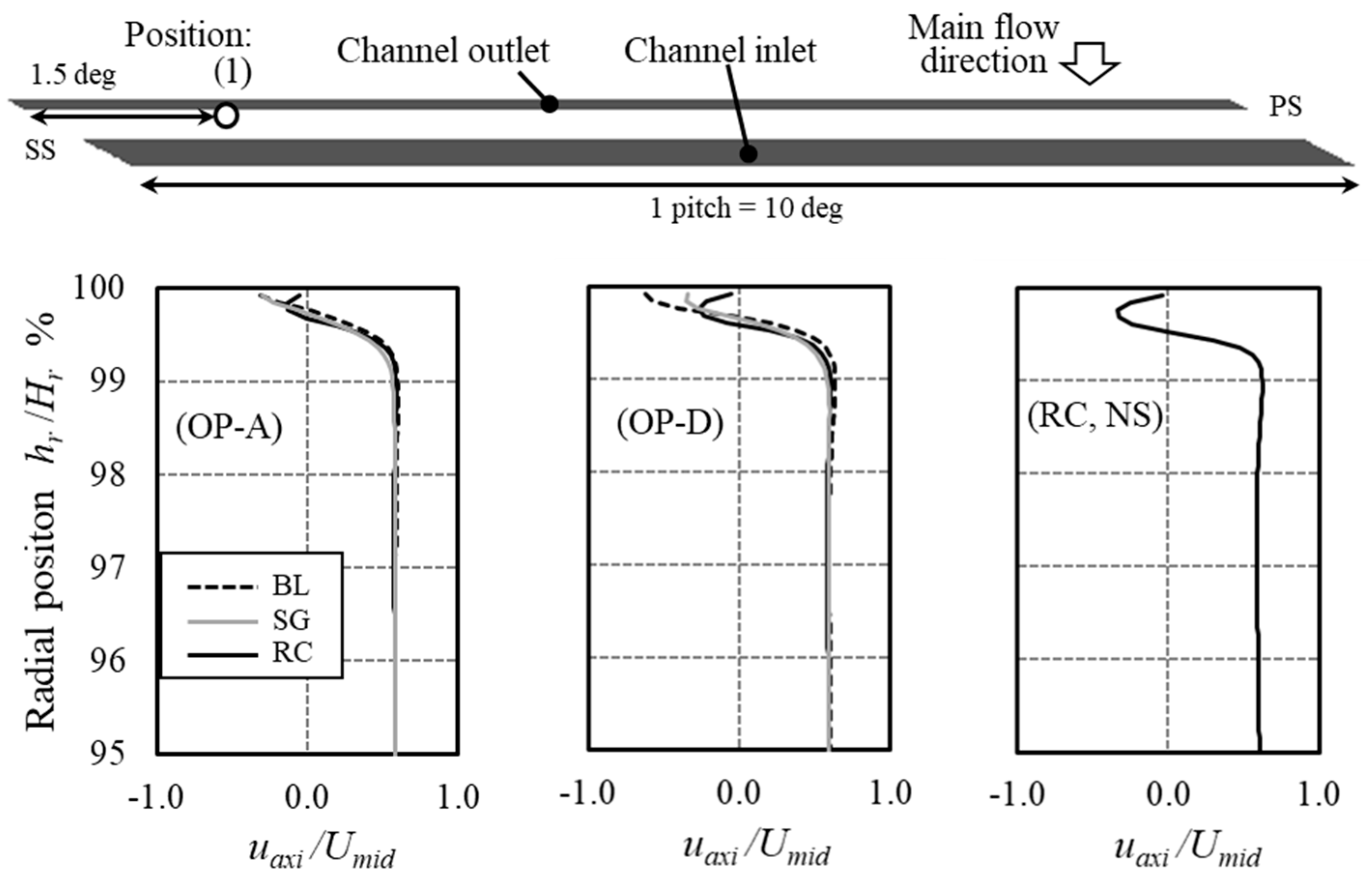
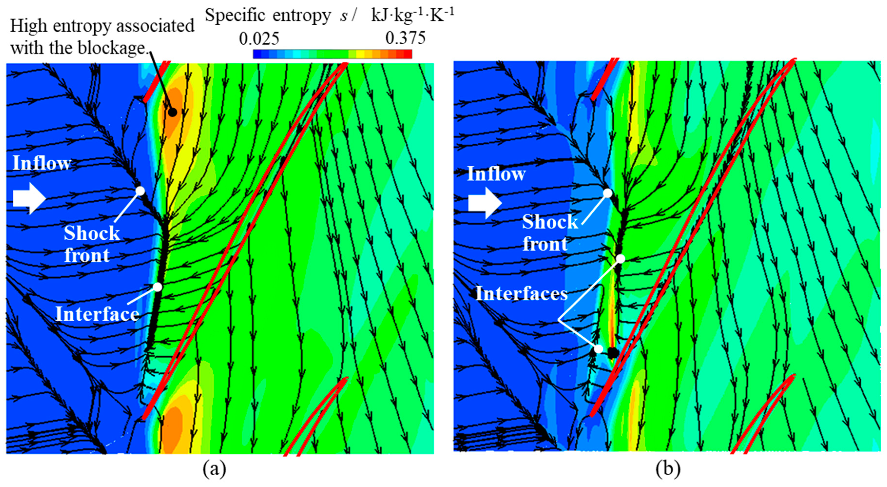
5.4. Flow Structures over the Casing Wall

Figure 9 highlights how the recirculation casing wall was effective in reducing the passage blockage caused by the interaction between the tip leakage vortex and the rotor blade leading edge shock. The changes in the near-casing flow pattern that deliver this improvement are analyzed in Figure 16, which shows the surface streamlines on the casing wall and the entropy distribution. Over the casing wall, a substantial area was wetted by reversed flow. Figure 16 shows the interface between the rotor tip clearance flow and the main flow over the casing, which is labelled “Interface” in Figure 16. This interface, in the configuration without casing treatment of Figure 16a, runs into the shock front, creating a high-entropy region associated with the flow blockage identified in Figure 9 and in Figure 10. By adding the recirculation channel wall treatment, Figure 16b shows that the interface of Figure 16a is split into two separate interfaces. The second interface occurs further downstream than in Figure 16a, at a greater axial distance from the rotor blade leading edge axial plane. The second interface was formed where the flow injection from the casing treatment collided with the tip leakage flow. This second interface was generated by the physical requirement of separating flows of opposing directions, namely, the tip leakage flow and the injected flow, by a zero-velocity boundary. The flow blockage region, which the entropy iso-levels indicate as developing downstream of the interface axial location in Figure 16a,b, is shown to have been reduced in Figure 16b. Flow injection from the RC mitigates the reverse flow near the casing and allows the blade’s leading ledge shockwave to move axially downstream. The interaction between this shockwave and the tip leakage vortex was, therefore, also delayed axially, mitigating the vortex breakdown, which was a significant entropy production process near the pressure side of the blade.

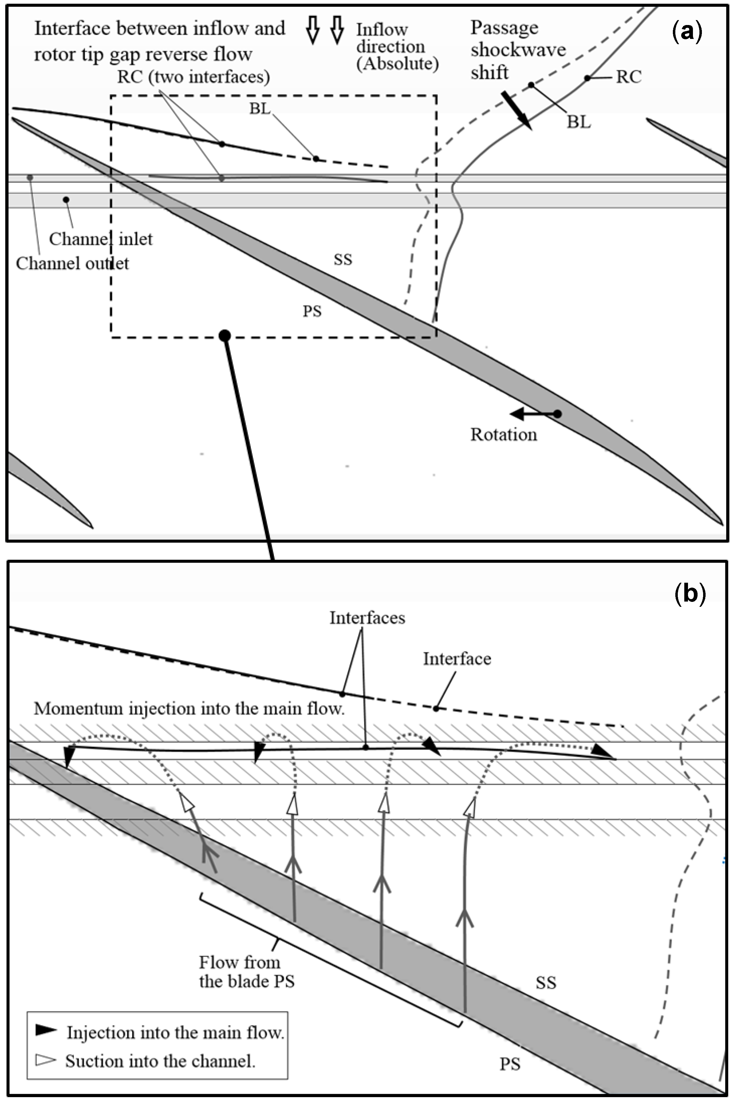
5.5. Summary of the Working Principle of the Casing Channel

Figure 17 brings together in a schematic the main effects of the recirculation channel casing treatment identified in the previous sections. The main passage flow runs from top-to-bottom as shown by the white arrows in Figure 17a. As the rotor blade rotates below the axisymmetric channel, the pressure difference between the blade pressure side and the blade suction side works in combination with the positive axial static pressure gradient to drive fluid from the channel inlet to the channel outlet, where the nozzle shape of the channel generates an outflow of high-axial momentum in the positive axial direction. This induced flow is illustrated in Figure 17b, which is a magnification of the dashed-line inset of Figure 17a. As the working fluid runs through the recirculation channel in the casing, it spreads pitch-wise outwards from the blade camber line, affecting the incoming flow across a larger portion of the blade pitch. Close to the untreated casing, an interface sets between the oncoming and tip leakage flow along the dashed line labelled “Interface” in Figure 17. By adding the recirculation channel treatment, the dashed-line interface is replaced by two interfaces, shown by continuous lines in Figure 17, one of which is further downstream. This new downstream flow structure constrains the region of reverse flow, relocating it further downstream in the main passage. This reduces the volume of reverse flow over the casing wall, which reduces the flow blockage near the casing wall. In turn, this provides a benefit to the stall margin of Rotor 37.
These changes are beneficial to the rotor performance. Adding axial momentum through the channel outlet reduced the extent of the reverse flow near the casing wall. This addition of axial momentum also reduced the size of the vortex breakdown, which occurred due to the interaction between the tip leakage vortex and the passage shockwave. This reduced the flow incidence angle at the rotor blade tip and consequently delayed the onset of separated flow on the blade suction side, which triggered a stall at the rotor blade tip. As a result, stall inception was delayed by the recirculation channel casing treatment without compromising the rotor adiabatic efficiency.

6. Conclusions

A recirculating type casing treatment was explored numerically for the treatment of secondary flows linked to stall onset at the casing of axial rotors in axial compressors. This was aimed at addressing the current gap between academic research on casing treatments and their widespread adoption in high-performance engine designs. A targeted literature review on casing treatments points to possible concerns about the design complexity and robustness, the added weight, as well as having to trade off significant gains in stall margin against a stage isentropic efficiency penalty along the engine operating line. This led to favoring three-dimensional blading rather than casing treatments for improving the stall margin in current generation jet engines that use highly loaded axial compressors. The design concept explored in this work has shown potential for addressing some of these concerns. As such, it has the potential impact of opening the use of combinations of casing treatments and three-dimensional blading in flying high-performance engines. This paper has reported seminal work on an axisymmetric recirculation channel in the casing of the NASA Rotor 37 test case that provided a stall margin gain higher than that from using the square groove casing used in past engine designs, while providing no component efficiency drop.
Steady RANS predictions indicate the recirculation casing has a number of attractive features. This channel provided a self-adjusting control flow of the rotor tip leakage that did not require any sensor nor actuator, so that this control system is strictly passive. The control flow through the passage was shown to be induced by the pressure difference across the rotor blade tip, so that the controlling flow is active where tip leakage occurs, and it is essentially inactive away from the moving blade. This passive flow control is therefore self-activating. As the controlling flow through the recirculation channel is driven by the rotor loading, the recirculating flow is predicted to provide more controlling axial momentum at the higher loading conditions. These are the conditions at which larger rotor tip separated flow areas initiate rotor tip stall in the rotor geometry without this casing treatment.
By analyzing the three-dimensional RANS flow predictions, a good insight was obtained into the mechanism. The recirculating flow occurs by the pressure difference between the pressure side and the suction side of the rotor blade. This additional flow mitigates the flow blockage over the shroud wall, by modifying the interaction between the leading edge shock wave and the tip leakage vortex. By this mechanism, the recirculation channel improves the stall margin of a highly loaded rotor, susceptible to rotor tip stall.
This numerical investigation on a recirculation channel treatment for highly loaded axial rotors and compressors has shown good promise for this casing treatment concept. Further work on the optimization of the channel shape, the experimental verification of the design, and testing on a prototype engine may lead to its wide-spread adoption in high-performance aircraft engines.

Author Contributions

M.K. performed the simulations and analyzed the results, under the supervision of A.R.; M.K. and A.R. jointly wrote the paper.

Funding

M.K.’s Ph.D. was supported by the Japanese Acquisition Technology and Logistic Agency, Government of Japan. This research used the ALICE high-performance computing facility at the University of Leicester. Graphical rendering software licenses were originally acquired with EPSRC support on Grant GR/N23745/01.

Acknowledgments

The authors wish to acknowledge the insightful guidance on end-wall contouring design and axial compressor numerical modelling by Tie Chen, Christos Georgakis, and Peter Millington, GE Power, Rugby, UK.

Conflicts of Interest

The authors declare no conflict of interest.

Abbreviations

The following symbols and abbreviations are used in this manuscript:
Nomenclature
c z rotor blade tip axial chord, m
erelative error
h r radial position, m
H r height of the main passage, m
Iturbulence intensity
lturbulence length scale, m
Mnormalized momentum
m ˙ mass flow rate, kg s−1
Nnumber of rotor blades
Ppressure, Pa
r m refinement ratio
ufluid velocity, m s−1
Urotor blade speed, m s−1
y+near-wall resolution
γspecific heat ratio
ηadiabatic efficiency
θflow angle, deg
κthermal conductivity, W m−1 K−1
ρdensity, kg m−3
ω 3 rotational speed, rad s−1
Subscripts
axiaxial direction
chokedchoked condition
incomputational domain inlet boundary
midmid-span of the rotor blade
nmesh index
outcomputational domain outflow boundary
RRichardson’s extrapolation
radradial direction
refreference
tantangential direction
tiptip of the rotor blade
0stagnation condition
1station 1
4station 4
Superscripts
-mass-averaged value
Abbreviations
BLbaseline
LErotor blade tip leading edge
RCrecirculation channel
SGsquare groove

References

  1. Camp, T.R.; Day, I.J. A Study of Spike and Modal Stall Phenomena in a Low-Speed Axial Compressor. J. Turbomach. 1997, 120, 393–401. [Google Scholar] [CrossRef]
  2. Davis, R.L.; Yao, J. Computational Approach for Predicting Stall Inception in Multistage Axial Compressors. J. Propuls. Power 2007, 23, 257–265. [Google Scholar] [CrossRef]
  3. Owczarek, J.A. On Initiation of Stall in Axial Flow Compressors. Int. J. Turbomach. Propuls. Power 2017, 2, 5. [Google Scholar] [CrossRef]
  4. Haug, J.P.; Niehuis, R. Full Annulus Simulations of a Transonic Axial Compressor Stage with Distorted Inflow at Transonic and Subsonic Blade Tip Speed. Int. J. Turbomach. Propuls. Power 2018, 3, 7. [Google Scholar] [CrossRef]
  5. Gallimore, S.J.; Bolger, J.J.; Cumpsty, N.A.; Taylor, M.J.; Wright, P.I.; Place, J.M.M. The Use of Sweep and Dihedral in Multistage Axial Flow Compressor Blading—Part 1: University Research and Methods Development. J. Turbomach. 2002, 124, 521–532. [Google Scholar] [CrossRef]
  6. Gallimore, S.J.; Bolger, J.J.; Cumpsty, N.A.; Taylor, M.J.; Wright, P.I.; Place, J.M.M. The Use of Sweep and Dihedral in Multistage Axial Flow Compressor Blading—Part 2: Low and High-Speed Designs and Test Verification. J. Turbomach. 2002, 124, 533–541. [Google Scholar] [CrossRef]
  7. Vo, H.D. Rotating Stall Suppression in Axial Compressors with Casing Plasma Actuation. J. Propuls. Power 2010, 26, 808–818. [Google Scholar] [CrossRef]
  8. Reutter, O.; Rozanski, M.; Hergt, A.; Nicke, E. Advanced Endwall Contouring for Loss Reduction and Outflow Homogenization for an Optimized Compressor Cascade. Int. J. Turbomach. Propuls. Power 2017, 2, 1. [Google Scholar] [CrossRef]
  9. Osborn, M.W.; Lewis, W.G., Jr.; Heidelberg, J.L. Effect of Several Porous Casing Treatments on Stall Limit and on Overall Performance of an Axial-Flow Compressor Rotor; No. NASA/TN D-6537; NASA: Washington, DC, USA, 1971.
  10. Schnell, R.; Voges, M.; Mönig, R.; Müller, M.W.; Zschnerp, C. Investigation of Blade Tip Interaction with Casing Treatment in a Transonic Compressor—Part 2: Numerical Results. J. Turbomach. 2010, 133, 011008. [Google Scholar] [CrossRef]
  11. Gourdain, N.; Leboeuf, F. Unsteady Simulation of an Axial Compressor Stage with Casing and Blade Passive Treatment. J. Turbomach. 2009, 131, 021013. [Google Scholar] [CrossRef]
  12. Wadia, A.R.; James, F.D. F110-GE-132: Enhanced Power Through Low-Risk Derivative Technology. J. Turbomach. 2000, 123, 544–551. [Google Scholar] [CrossRef]
  13. Legras, G.; Trébinjac, I.; Gourdain, N.; Ottavy, X.; Castillon, L. A Novel Approach to Evaluate the Benefits of Casing Treatment in Axial Compressors. Int. J. Rotating Mach. 2012, 2012, 1–19. [Google Scholar] [CrossRef]
  14. Chen, H.; Huang, X.; Shi, K.; Fu, S.; Ross, M.; Bennington, M.A.; Cameron, J.D.; Morris, S.C.; McNulty, S.; Wadia, A. A Computational Fluid Dynamics Study of Circumferential Groove Casing Treatment in a Transonic Axial Compressor. J. Turbomach. 2014, 136, 031003. [Google Scholar] [CrossRef]
  15. Cevik, M.; Vo, H.D.; Yu, H. Casing Treatment for Desensitization of Compressor Performance and Stability to Tip Clearance. J. Turbomach. 2016, 138, 121008. [Google Scholar] [CrossRef]
  16. Houghton, T.; Day, I. Enhancing the Stability of Subsonic Compressors Using Casing Grooves. J. Turbomach. 2010, 133, 021007. [Google Scholar] [CrossRef]
  17. Houghton, T.; Day, I. Stability Enhancement by Casing Grooves: The Importance of Stall Inception Mechanism and Solidity. J. Turbomach. 2011, 134, 021003. [Google Scholar] [CrossRef]
  18. Sakuma, Y.; Watanabe, T.; Himeno, T.; Kato, D.; Murooka, T.; Shuto, Y. Numerical Analysis of Flow in a Transonic Compressor with a Single Circumferential Casing Groove: Influence of Groove Location and Depth of Flow Instability. J. Turbomach. 2013, 136, 031017. [Google Scholar] [CrossRef]
  19. Mao, X.; Liu, B.; Zhao, H. Numerical Investigation for the Impact of Single Groove on the Stall Margin Improvement and the Unsteadiness of Tip Leakage Flow in a Counter-Rotating Axial Flow Compressor. Energies 2017, 10, 1153. [Google Scholar] [CrossRef]
  20. Koff, S.G.; Mazzawy, R.S.; Nikkanen, J.P.; Nolcheff, N.A. Case Treatment for Compressor. U.S. Patent 5,282,718, 3 August 1992. [Google Scholar]
  21. Hathaway, M.D. Self-Recirculating Casing Treatment Concept for Enhanced Compressor Performance; No. NASA/TM-2002-211569; NASA: Washington, DC, USA, 2002.
  22. Dinh, C.T.; Ma, S.B.; Kim, K.Y. Effect of a Circumferential Feed-Back Channel on Aerodynamic Performance of a Single-Stage Transonic Axial Compressor. In Proceedings of the ASME Turbo Expo 2017: Turbomachinery Technical Conference and Exposition, Charlotte, NC, USA, 26–30 June 2017. Paper No. GT2017-63536. [Google Scholar] [CrossRef]
  23. Yang, M.; Martinez-Botas, R.; Zhang, Y.; Zheng, X. Effect of Self-Recirculation-Casing Treatment on High Pressure Ratio Centrifugal Compressor. J. Propul. Power 2016, 32, 602–610. [Google Scholar] [CrossRef]
  24. Tesla, N. Valvular Conduit. U.S. Patent 1,329,559, 2 February 1916. [Google Scholar]
  25. Reid, L.; Moore, D. Design and Overall Performance of Four Highly Loaded, High-Speed Inlet Stages for an Advanced High-Pressure-Ratio Core Compressor; No. NASA/TP-1337; NASA: Washington, DC, USA, 1978.
  26. Dunham, J. CFD Validation for Propulsion System Components; No. AGRAD-AR-355; The Advisory Group for Aerospace Research and Development (NATO): Neuilly sur Seine, France, 1998. [Google Scholar]
  27. Arima, T.; Sonoda, T.; Shirotori, M.; Tamura, A.; Kikuchi, K. A Numerical Investigation of Transonic Axial Compressor Rotor Flow Using a Low-Reynolds-Number k-ε Turbulence Model. J. Turbomach. 1999, 121, 44–58. [Google Scholar] [CrossRef]
  28. Roache, P.J. Perspective: A Method for Uniform Reporting of Grid Refinement Studies. J. Fluid. Eng. 1994, 116, 405–413. [Google Scholar] [CrossRef]
  29. Shih, T.-H.; Liou, W.W.; Shabbir, A.; Yang, Z.; Zhu, J. A New k-ε Eddy-Viscosity Model for high Reynolds Number Turbulent Flows—Model Development and Validation. Comput. Fluids 1995, 24, 227–238. [Google Scholar] [CrossRef]
  30. Tsederberg, N.V. Thermal Conductivity of Gases and Liquids; Edward Arnold: London, UK, 1965; ISBN 026220004X. [Google Scholar]
  31. Roe, P.L. Characteristic-Based Schemes for the Euler Equations. Annu. Rev. Fluid Mech. 1986, 18, 337–365. [Google Scholar] [CrossRef]
  32. Weiss, J.M.; Maruszewski, J.P.; Smith, W.A. Implicit Solution of the Navier-Stokes Equations on Unstructured Meshes. In Proceedings of the 13th Computational Fluid Dynamics Conference, Snowmass Village, CO, USA, 29 June–2 July 1997. Paper No. AIAA-97-2103. [Google Scholar] [CrossRef]
  33. Denton, J.D. Lessons from Rotor 37. J. Therm. Sci. 1997, 6, 1–13. [Google Scholar] [CrossRef]
  34. Suder, K. Experimental Investigation of the Flow Field in a Transonic, Axial Flow Compressor with Respect to the Development of Blockage and Loss; No. NASA/TM-107310; NASA: Washington, DC, USA, 1996.
  35. Hah, C. Large Eddy Simulation of Transonic Flow Field in NASA Rotor 37; No. NASA/TM-2009-215627; NASA: Washington, DC, USA, 2009.
  36. Kim, D.-W.; Kim, J.-H.; Kim, K.-Y. Aerodynamic Performance of an Axial Compressor with a Casing Groove Combined with Injection. In Proceedings of the 13th Computational Fluid Dynamics Conference, Snowmass Village, CO, USA, 29 June–2 July 1997. Paper No. AIAA-97-2103. [Google Scholar] [CrossRef]
  37. Cumpsty, N.A. Compressor Aerodynamics; Longman Scientific & Technical: London, UK, 1989; ISBN 058201364x. [Google Scholar]
  38. Cumpsty, N.A. Jet Propulsion: A Simple Guide to the Aerodynamic and Thermodynamic Design and Performance of Jet Engine; Cambridge University Press: Cambridge, UK, 1997; ISBN 0521596742. [Google Scholar]
Figure 1. The concept of the self-adjusting passive control technique. (a) Conceptual sketch of the recirculation channel (RC) for the axial compressor rotor; (b) meridional cross-section of the recirculation channel. All dimensions are normalized by the rotor blade tip chord cz and all axial locations are referenced to the rotor blade tip Leading Edge (LE).
Ijtpp 04 00005 g001
Figure 2. Meridional sketch of the NASA Rotor 37 used as the benchmark axial rotor test case [26].
Ijtpp 04 00005 g002
Figure 3. Overview of the casing treatments applied over the NASA stage 37 rotor. (a) Square groove [18]; (b) recirculation channel.
Ijtpp 04 00005 g003
Figure 4. NASA Rotor 37 passage computational domain and mesh with circumferential recirculation channel.
Ijtpp 04 00005 g004
Figure 5. Error reduction with increasing spatial resolution based on Richardson’s extrapolation. (a) Adiabatic efficiency; (b) local static pressure near the rotor pressure side tip.
Ijtpp 04 00005 g005
Figure 6. Overall performance characteristics of the NASA Rotor 37. Comparison between the current predictions and the experimental data. (a) Total pressure ratio; (b) adiabatic efficiency.
Ijtpp 04 00005 g006
Figure 7. Circumferentially mass-averaged radial profiles at Station 4 of Figure 4. Comparison between CFD and experimental data reported in [26,27]. (a) Normalized total pressure at Station 1; (b) normalized total pressure at Station 4; (c) normalized tangential velocity at Station 4; (d) flow angle at Station 4.
Ijtpp 04 00005 g007
Figure 8. Overall compressor performance characteristics showing the impact of the investigated casing treatments. (a) Total pressure ratio across the rotor; (b) adiabatic efficiency.
Ijtpp 04 00005 g008
Figure 9. Analysis of the passage flow structures showing comparisons of the vortex breakdown and of the low-velocity region. (a) Streamlines and static pressure contours on 95% span surface (ΔP = 10kPa), BL (OP-D); (b) relative Mach number contours on 95% span surface, BL (OP-D); (c) streamlines and static pressure contours on 95% span surface (ΔP = 10kPa), SG (OP-D); (d) relative Mach number contours on 95% span surface, SG (OP-D); (e) streamlines and static pressure contours on 95% span surface (ΔP = 10kPa), RC (OP-D); (f) relative Mach number contours on 95% span surface, RC (OP-D).
Ijtpp 04 00005 g009
Figure 10. Contours of flow angle showing the flow structure near the rotor blade LE at 0.99 blade span. (a) BL (OP-D); (b) SG (OP-D); (c) RC (OP-D); (d) RC (NS).
Ijtpp 04 00005 g010
Figure 11. Radial profiles of Reynolds-Averaged Navier–Stokes axial velocity predictions near the casing wall showing the change with the rotor loading. These radial profiles were extracted at the constant pitch-wise angle of Position (1) shown in the sketch above the graphs.
Ijtpp 04 00005 g011
Figure 12. Axial and tangential velocity distributions across the axial plane 1 mm downstream of the rotor blade row exit axial plane. (a) Contours of axial velocity viewed from downstream of the rotor; (b) circumferentially mass-averaged profiles of tangential velocity and of axial velocity.
Ijtpp 04 00005 g012
Figure 13. Streamlines showing the flow structure inside two different casing treatments. (a) Square groove (OP-D); (b) recirculation groove (OP-D).
Ijtpp 04 00005 g013
Figure 14. Distribution of the injected momentum in the axial direction showing an intense injection near the blade SS (OP-D).
Ijtpp 04 00005 g014
Figure 15. Variation in the injected flow momentum M, showing that M increases with compressor loading.
Ijtpp 04 00005 g015
Figure 16. Surface streamlines and the entropy contours near the casing wall showing the creation of flow interfaces near the rotor LE. (a) BL (OP-D); (b) RC (OP-D).
Ijtpp 04 00005 g016
Figure 17. Diagram summarizing the working principle of the casing channel.
Ijtpp 04 00005 g017
Table 1. Flow conditions used for the numerical model.
Variables Values
InletTotal pressure, P0inkPa101.325
Total temperature, T0inK288.15
Turbulence intensity, I%3
Turbulence length scale, lm0.0114
OutletStatic pressure, PoutkPaVaried from 101.3 to stall inception.
Table 2. Comparison of choked mass flow rate and of mass flow rate at the near-stall condition.
Choked Mass Flow Rate (kg s−1)Normalized Mass Flow Rate at Near-Stall Condition (%)
Experiment20.9391.9
(Stalled flow)
Kawase and Rona (this study)20.8492.3
Arima et al. [27]20.7792.4
Sakuma et al. [18]20.7892.1
Hah [35]20.9292.3
Kim et al. [36]-90.3
Table 3. Summary of the overall performance obtained by steady RANS simulations with and without the casing treatments.
BLSGRC
Stall Margin (SM)%13.0715.9318.14
ΔSM%0.002.855.07
Choked mass flow rate m ˙ chokedkg s−120.8320.8320.84
Adiabatic peak efficiency η%85.33785.30685.341
Δη%0.00−0.031+0.004
BL: Baseline casing; SG: Casing with Square Groove [12]; RC: Casing with Recirculation Channel.

