Abstract
For modern axial fans optimized for low self-noise, additional noise emission from guard grilles mounted downstream of the fan can become one of the dominant sources of sound. In the present case, the overall sound power level increases by up to 6 dB. Based on narrow-band acoustic measurements and numerical Lattice-Boltzmann simulations of wind tunnel setups using round wires, it is observed that periodic flow separations behind the wires (von Kármán vortex street) lead to a pronounced hump in the noise spectrum. This occurs in a frequency range that corresponds to the grille-induced noise increase observed with an axial fan under comparable flow conditions. By examining various wire geometries, it was found that disrupting the von Kármán vortex street along the longitudinal direction of the wire and reducing the homogeneity of flow separation can significantly decrease sound generation. As a result, a guard grille prototype incorporating the most promising structures was manufactured for a modern low-noise axial fan. Comparative experimental results for the fan are presented.
1. Introduction
In many fan applications, guard grilles are installed on the suction and/or pressure side to prevent contact with rotating components. It is well established that such grilles can significantly increase acoustic emissions. For low self-noise fans, grille-induced noise often dominates the overall sound power.
Figure 1a depicts an axial fan with a diameter of D2 = 630 mm, as commonly employed in heat pump systems. Figure 1b illustrates the same fan equipped with a downstream guard grille composed of concentric round wires, stabilized by a crosswise support structure. This structure connects the grille to the outer fan housing and, in the present configuration, also serves as a mount for the motor and impeller assembly.
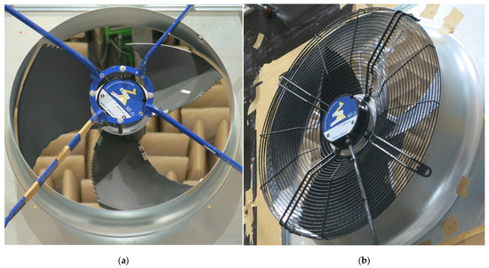
Figure 1.
Experimental setup for acoustic measurements of an axial fan: (a) configuration without downstream guard grille; (b) configuration with downstream guard grille comprising concentric round wires and structural support elements.
The noise emission of the two fan configurations was experimentally investigated in the ZIEHL-ABEGG anechoic test facility. This facility comprises two large anechoic chambers separated by a partition wall, onto which the fan and nozzle were mounted. For further details regarding the ZIEHL-ABEGG anechoic test facility, refer to Section 2.1 Wind Tunnel Configuration. The sound power was measured independently on the suction and pressure sides, employing an enveloping surface approach. Figure 2a presents the dimensionless static pressure rise ψstat and the specific A-weighted overall sound power level on the pressure side LWA6spec as functions of the specific diameter δ, recorded at a rotation speed of n = 770 rpm.
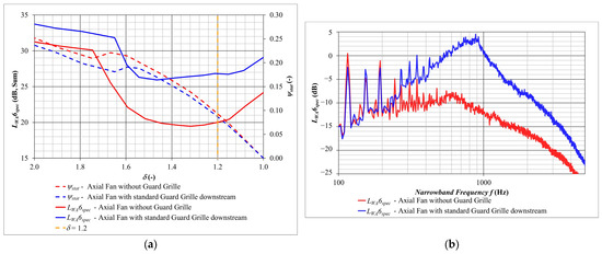
Figure 2.
Experimental results for an axial fan operating at n = 770 rpm, comparing configurations without (red) and with (blue) a downstream guard grille: (a) specific A-weighted overall sound power level on the pressure side, LWA6spec, as a function of the specific diameter δ; (b) corresponding A-weighted narrowband sound power spectrum at δ = 1.2.
The specific diameter δ depends on the dimensionless volume flow rate φ and the dimensionless static pressure rise ψstat according to the relation δ = ψstat1/4/φ1/2. The dimensionless volume flow rate φ is defined as φ = QV/(u2 π D22 0.25), where QV is the volume flow rate, u2 is the circumferential velocity and D2 is the outer diameter of the impeller. The dimensionless static pressure rise ψstat is given by ψstat = Δpstat/(0.5 ρ u22), where Δpstat is the static pressure rise, u2 is the circumferential velocity and ρ is the fluid density [1].
The presence of the guard grille leads to a marked increase in noise emission when compared to the unshielded fan. This increase is particularly pronounced at low δ values, corresponding to higher volume flow rates, where LWA6spec rises by approximately 6–7 dB. To gain deeper insights into this effect, Figure 2b illustrates the spectral distribution of LWA6spec at δ = 1.2. The spectrum of the fan equipped with a guard grille reveals a distinct hump peaking around f = 900 Hz. This spectral feature persists across various operating conditions and shifts toward higher frequencies with increasing volume flow. Similar observations were reported by Schneider et al. [2] for axial fans fitted with guard grilles.
In the case of a cylinder in crossflow—a simplified model for the wires of a guard grille—periodic flow separations, known as the Kármán vortex street [3], can be observed. This flow phenomenon generates tonal or narrowband acoustic emissions. The vortex shedding frequency f, which corresponds to the dominant frequency of the emitted noise, depends on the free-stream velocity v∞ (estimated from the volume flow rate and the nozzle outlet area), the wire diameter Dwire, and the Strouhal number Sr, according to the relation f = Sr v∞/Dwire (see [4,5,6]).
The Strouhal number itself varies as a function of the Reynolds number Re. For the performance curve presented in Figure 2a, the maximum flow velocity is estimated to be v∞ = 8 m/s without blockage by the guard grille and v∞ = 11 m/s with blockage. Locally, in the immediate downstream region of the fan and for larger fan sizes or higher rotational speeds, even higher flow velocities can occur. Therefore, the relevant velocity range for investigating and optimizing the acoustic behaviour of guard grille wires is v∞ = [4, …, 20] m/s, corresponding to a Reynolds number range of Re = [650, …, 3250]. Based on [6], a representative Strouhal number of Sr = 0.21 can be assumed.
For the operating point shown in Figure 2b at δ = 1.2, the upstream velocity is estimated to be v∞ ≈ 7 m/s without the grille and ≈9.5 m/s with grille blockage, using a wire diameter of Dwire = 2.5 mm. This yields a vortex shedding frequency of approximately 600–900 Hz (assuming Sr = 0.21), which corresponds well to the prominent hump observed in the narrowband spectrum in Figure 2b.
Foundational research on sound generation by vortex shedding from cylindrical structures in fluid flow is provided by Blevins [7], who offers a comprehensive overview of both theoretical principles and experimental observations. Vortex shedding is identified as a dipole sound source, producing periodic acoustic tones in applications such as power lines and heat exchangers. Moreau et al. [8] examined flow-induced noise from a wall-mounted finite-length cylinder in cross-flow. Unlike infinite-length cylinders, finite configurations introduce additional noise mechanisms—particularly tip and junction effects—which are less relevant for fan guard grilles. Zdravkovich [9] investigated the aeroelastic behaviour of two interacting cylinders in various arrangements, focusing on flow-induced oscillations. The presence of a neighbouring cylinder significantly alters the flow field and can lead to synchronization between vortex shedding and structural oscillation frequencies, depending on spacing, Reynolds number, and damping.
Noise generation from tandem cylinder arrangements was studied by Hutcheson et al. [10] and Geyer et al. [11]. Hutcheson et al. [10] analyzed vortex shedding noise as a dipole source, showing its dependence on flow velocity and cylinder diameter within a Reynolds number range of 3.8 × 10³ to 105. Tandem configurations revealed strong wake interference affecting downstream noise generation, while side-by-side setups showed complex interactions influenced by spacing. Geyer et al. conducted experiments in a small aeroacoustic wind tunnel, investigating far-field noise and flow fields for various spacings, diameters (18–30 mm), flow velocities (10–40 m/s), and inflow turbulence. Their findings confirmed that the wake of the upstream cylinder strongly influences the tonal noise of the downstream cylinder.
For noise reduction, Hutcheson et al. [10] tested wire wraps and collar distributions, which disrupted spanwise coherence and reduced vortex shedding noise. Geyer [12] explored porous materials, showing that increased porosity, thickness, and reduced airflow resistivity effectively narrowed the tonal peak in the sound spectrum. Li et al. [13] studied the impact of helical grooves on aerodynamic noise and flow behavior, concluding that optimized groove geometry can significantly reduce vortex shedding noise over a Reynolds number range of 2.8 × 10⁴ to 8.6 × 10⁴. Jia et al. [14] applied reinforcement learning to actively control flow around elliptical cylinders, successfully suppressing vortex shedding, reducing drag, and minimizing lift fluctuations.
The literature already offers a variety of investigations and optimization approaches for cylinders in cross-flow. However, the industrial applicability of some proposed methods—such as porous materials or helically structured wires—is limited or not feasible for the thin wires typically used in fan guard grilles. Therefore, the objective of this work is to investigate the noise generation of such wires and to develop an industrially viable method for reducing their acoustic emissions.
To further investigate the noise generation mechanisms of various wire geometries, a dedicated wind tunnel setup was designed and constructed for experimental acoustic measurements (Section 2, Experimental Investigation). Additionally, unsteady Lattice-Boltzmann simulations of the wire arrangements within this setup were conducted to complement the experimental data (Section 3, Numerical Investigation). Based on the results, the wire geometry was optimized (Section 4, Noise Reduction through Surface Modification of Wires). In the subsequent step, the most promising optimization technique was applied to a complete guard grille. First results are presented in Section 5, Optimization of a Real Fan Guard Grille.
2. Experimental Investigation
2.1. Wind Tunnel Configuration
To investigate the aeroacoustic characteristics of flow around wire arrangements, a dedicated wind tunnel was designed and fabricated using additive manufacturing (Figure 3 and Figure 4a). Figure 3 shows a schematic cross-section of the wind tunnel. The setup features a smooth inlet and outlet cone, both with circular cross-sections, connected by a central flow section with a square cross-section. Within this central region, up to nine wires with diameter Dwire = [1, …, 6] mm can be mounted in parallel at equidistant spacing (Figure 4b), with a centre-to-centre distance of 10 mm—mirroring the configuration of the guard grille shown in Figure 1b. The geometry of the inlet and outlet transitions is carefully designed to ensure smooth flow development, while a long calming section promotes a stable and reproducible inflow. Although a fully homogeneous flow cannot be guaranteed due to boundary layer effects, the configuration ensures sufficient reproducibility for relative comparisons of different wire geometries in an industrial context.
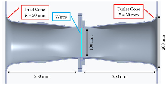
Figure 3.
Schematic cross-section of the wind tunnel setup for experimental investigation of wire-induced noise.
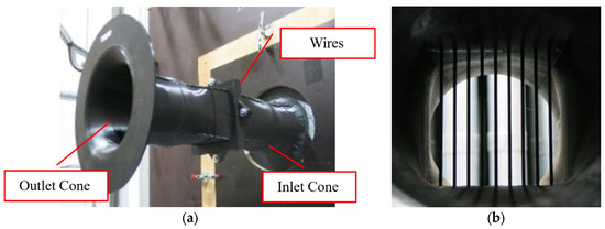
Figure 4.
Wind tunnel setup for experimental investigation of wire-induced noise: (a) 3D-printed wind tunnel with smooth inlet and outlet cones; (b) central test section featuring an array of nine equally spaced wires.
The wires under investigation may be fabricated from metal, coated materials, or produced via high-resolution 3D printing using a resin printer (Elegoo Jupiter 6K). For acoustic testing, the wind tunnel is installed centrally within the partition wall of the ZIEHL-ABEGG anechoic test facility. In this facility, the aerodynamic performance data, such as static pressure and volume flow, and the acoustic measurements are recorded simultaneously. Acoustic measurements are conducted on both the upstream and downstream sides of the wind tunnel using twelve microphones positioned on an enveloping hemispherical measurement surface with a radius of 1.5 m, in accordance with DIN EN ISO 3745 (Class 1) [15] and ISO 13347-3 [16]. Broadband absorbers on the side walls of the anechoic chambers ensure measurements under free-field conditions, where acoustically no significant reflections occur. Using the facility’s auxiliary fan upstream of the wind tunnel, a range of flow velocities v∞ is generated.
2.2. Experimental Results
Figure 5 presents the experimental results for the acoustic emission of nine equally spaced round wires with a diameter of Dwire = 2.5 mm positioned in the wind tunnel, as previously shown in Figure 4b. The overall pressure-side sound power level LW6 increases markedly with the upstream flow velocity v∞ (Figure 5a). The self-noise of the empty wind tunnel, recorded without wires, remains negligible for v∞ ≥ 12 m/s (Figure 5a). Figure 5b shows the narrowband spectra of the wire configuration for various flow velocities v∞, determined from the measured volume flow rate and the square cross-sectional area at the wire location, neglecting blockage effects. A pronounced spectral hump is observed for all v∞, with both its frequency and magnitude increasing with flow velocity—consistent with the behaviour expected from a von Kármán vortex street [3]. At these frequencies and velocities, the background noise of the wind tunnel is negligible. At lower free-stream velocities v∞, background noise becomes more dominant and the spectral humps can no longer be distinctly observed. In the range of 3000 to 4000 Hz the second harmonics of these spectral humps are observed. Additional peaks around 300 Hz are considered negligible, as they are also part of the background noise of the wind tunnel. It is therefore assumed that effects at the in- or outlet of the wind tunnel cause this low-frequency noise.
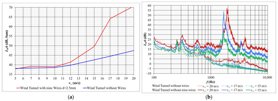
Figure 5.
Experimental results for the acoustic emission of nine equally spaced round wires (Dwire = 2.5 mm): (a) overall pressure-side sound power level LW6 as a function of the upstream flow velocity v∞; (b) comparison of narrowband spectra LW6 as a function of frequency for different values of v∞.
Figure 6 illustrates the narrowband spectra from Figure 5b as a function of Strouhal number Sr. In line with theoretical expectations, the observed spectral hump occurs, for all v∞, at nearly the same Strouhal number. However, assuming no blockage, the observed humps appear at Sr ≈ 0.24–0.25, which is higher than the theoretical value of Sr = 0.21. Accounting blockage effects caused by the wire array, the hump appears at Sr ≈ 0.185–0.195, showing slightly better agreement with the theoretical prediction. Nevertheless, for better comparison between different wire configurations, Sr is calculated using v∞ without accounting for blockage.
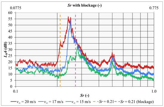
Figure 6.
Experimental results for the acoustic emission of nine equally spaced round wires (Dwire = 2.5 mm): narrowband spectra LW6 out of Figure 5b as a function of Strouhal number Sr calculated with and without blockage.
The corresponding vortex shedding frequencies are summarized in Table 1. The experimentally observed tonal frequency fexp is consistently higher than the theoretical vortex shedding frequency ftheo, calculated using Sr = 0.21 and assuming no blockage. When blockage due to the wire array is considered, the adjusted theoretical frequency ftheo,9wires shows significantly better agreement with the measurements. Residual discrepancies are likely due to inhomogeneities in the local flow field caused by boundary layer development and the transition of the wind tunnel’s cross-section from circular to square. At the two lowest free-stream velocities v∞, the background noise of the wind tunnel becomes non-negligible, making the spectral humps at the vortex shedding frequency difficult to clearly identify.

Table 1.
Comparison of the theoretical vortex shedding frequency ftheo (without blockage), the corrected theoretical frequency ftheo,9wires (accounting for blockage by nine wires), the experimentally observed hump frequency fexp (nine-wire setup), and the numerically predicted hump frequency fsim from simulation (single-wire setup).
In further experiments with Dwire = [1.5, 2.5, 3.5] mm, the relative variation in the emitted noise frequency, f, was found to be consistent with the theoretical relationship between Dwire and f. This confirms that the conceived wind tunnel setup provides sufficiently reproducible flow conditions for subsequent investigations aimed at optimizing wire design for aeroacoustic performance.
3. Numerical Investigation
3.1. Numerical Setup
To gain deeper insights into the flow-induced noise mechanisms, numerical simulations were carried out using PowerFLOW 5.5a, a commercial Lattice-Boltzmann Method (LBM) solver. The LBM inherently operates in a transient and weakly compressible regime, enabling direct access to both hydrodynamic sound source mechanisms and acoustic propagation. It resolves the time-space evolution of a truncated particle distribution function on a lattice grid, with particle collisions driving the system towards equilibrium via a collision operator. The method employs 19 discrete velocity directions, sufficient to recover the compressible Navier–Stokes equations for a perfect gas under low Mach number, isothermal conditions [17]. In PowerFLOW, the model utilizes a single relaxation time linked to the dimensionless laminar kinematic viscosity [18]. For turbulent flow modelling, this relaxation time is replaced by an effective turbulent relaxation time derived from a systematic Renormalization Group procedure, as detailed in [19]. This approach enables resolution of both large-scale flow structures within the domain and smaller turbulent eddies near surfaces in the spirit of a Large Eddy Simulation (LES).
To reduce computational cost, a simplified geometry of the wind tunnel was modelled, as shown in Figure 7. The model excludes the two anechoic chambers used in the experimental setup. The tunnel itself consists of a 1 m inlet channel and a 1.5 m outlet channel, both with a constant square cross-section of 150 mm. Wire arrangements—either single or in arrays—can be inserted between inlet and outlet sections. Figure 8 provides a detailed view of the computational domain near the wires, illustrating a configuration with 15 wires (a) and a single wire (b) in the simplified wind tunnel model. Boundary conditions are imposed as follows: a constant atmospheric pressure of p = 101,325 Pa is defined at the inlet (left yellow surface), while a volumetric flow rate QV is imposed at the outlet (right yellow surface), thereby controlling the upstream velocity v∞. The tunnel walls are modelled as rigid, acoustically reflective surfaces without damping, allowing for channel modes and potential signal reflections. Nevertheless, relative comparisons of different configurations remain meaningful. The fluid was defined as air at 20 °C with the following properties: density of 1.204 kg/m3, kinematic viscosity of 1.48 × 10⁻⁵ m2/s and molecular weight of 28.97 kg/kmol.

Figure 7.
Computational domain of the simplified wind tunnel model used for Lattice-Boltzmann simulations, including inlet and outlet channels, wire arrangement region, and boundary conditions for flow and pressure specification at the in- and outlet.
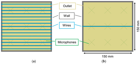
Figure 8.
Detailed view of the computational domain near the wires: configuration of 15 wires (a) and a single wire (b) in the simplified wind tunnel model.
The mesh is defined via nested refinement zones, with each level halving the grid spacing. In the critical region around the wires—25 mm upstream and 115 mm downstream—the cell size is refined to 0.4 mm. The finest mesh, with a resolution of 0.1 mm, is applied within a 1 mm envelope surrounding the wire surfaces. For acoustic post-processing, nine virtual microphones are placed along several upstream and downstream cross-sections. Their signals are integrated across the entire cross-sectional area to obtain a representative total sound level. While capturing far-field acoustics would require microphones placed outside the tunnel, this would also entail significantly increased computational demand. Within the microphone regions, the mesh size is 0.8 mm. This results in a timestep of 1.649 × 10⁻⁷ s and an update frequency in the microphone region of 7.582 × 10⁵ Hz.
The simulation domain comprises approximately 141 million fluid cells and 8 million surface elements for a single wire configuration, and up to 168 million fluid cells and 11 million surface elements for 15-wire array. Simulations were performed for different upstream velocities v∞, defined via the outlet flow rate QV. To initialize the solution, a preliminary coarse-mesh simulation (minimum cell size 0.4 mm) was conducted, excluding the two finest mesh levels. Final high-resolution simulations covered a physical time span of 0.066 s, with acoustic data collected over the final 0.04 s of each run. Microphone signals were sampled at a rate of 1.896 × 10⁵ Hz to capture highly time-resolved data.
For the numerical investigations, wires of different diameters (Dwire = [1.5, 2.5, 3.5] mm) were simulated at upstream velocities (v∞ = [8, 10, 12, 15] m/s) either in an array of 15 wires or as a single wire. According to the experimental setup, the wires in the 15-wire configuration were evenly spaced with a centre-to-centre distance of 10 mm (Figure 8a).
3.2. Numerical Results
To validate the numerical model, simulation results are compared to experimental measurements obtained at the ZIEHL-ABEGG anechoic facilities, as described in Section 2.1, Wind Tunnel Configuration, and Section 2.2, Experimental Results.
Figure 9a presents the third-octave band spectra of the pressure-side sound power level LW6 for a single round wire with diameter Dwire = 2.5 mm in the virtual wind tunnel. Simulations were done at various upstream velocities v∞, with microphones positioned 125 mm downstream of the wire. For each velocity, a distinct hump is observed in the sound spectra. Plotted against the Strouhal number, it becomes evident that these humps consistently occur at approximately Sr ≈ 0.21, regardless of the velocity v∞—in good agreement with the theoretical prediction (Figure 9b). As in the experimental data (cf. Figure 5b), both the amplitude and the centre frequency of the spectral hump increase with increasing v∞, consistent with the theoretical behaviour of a von Kármán vortex street.
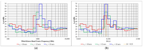
Figure 9.
Simulated third-octave band spectra of the pressure-side sound power level LW6 (a) as a function of frequency and (b) Strouhal number for a single round wire with Dwire = 2.5 mm in the wind tunnel, shown for different upstream velocities v∞.
Table 1 compares the theoretical vortex shedding frequency ftheo (calculated assuming no blockage and a Strouhal number Sr = 0.21) with the experimentally determined frequency fexp (for nine wires) and the numerically predicted centre frequency fsim (for a single wire in the LBM simulation), across several upstream velocities v∞. The numerical predictions agree well with the theoretical expectations.
Given the close correspondence between the simulated acoustic response and both experimental and theoretical results, it can be concluded that the simulation setup is sufficiently accurate for detailed investigations of the flow field, noise generation mechanisms, and acoustic optimization strategies with respect to wire geometry.
Figure 10 provides insight into the flow structures developing downstream of a single round wire. The vorticity magnitude visualized on a plane perpendicular to the wire axis (Figure 10a) clearly illustrates the formation of a von Kármán vortex street, consistent with the expected periodic shedding behaviour. In a horizontal plane through the wire axis (Figure 10b), a coherent vortex shedding pattern can be observed along the longitudinal direction of the wire, indicating a largely homogeneous separation behaviour over its span.
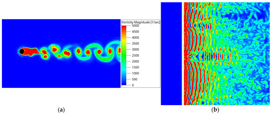
Figure 10.
Simulated flow field for a single round wire (Dwire = 2.5 mm) at an upstream velocity of v∞ = 10 m/s: (a) vorticity-magnitude plot in a plane perpendicular to the wire axis, showing the formation of a von Kármán vortex street; (b) vorticity-magnitude plot in a longitudinal plane through the wire axis, illustrating the coherent vortex-shedding pattern along the span of the wire.
4. Noise Reduction Through Surface Modification of Wires
4.1. Experimental and Numerical Investigation of Resin Printed Prototypes
Based on the hypothesis that coherent vortex shedding along the longitudinal axis of a wire is responsible for the prominent spectral hump observed in the acoustic measurements, the optimization strategies aim to disrupt this coherence and promote more irregular vortex shedding behaviour. Inspired by approaches from civil engineering, where Scruton helices have been successfully applied to reduce vortex-induced vibrations of cylindrical structures [20,21], this concept was adapted for axial fan guard grille wires. Helically structured wires were designed using 3D CAD and fabricated via high-resolution resin printing. Numerical simulations of these geometries revealed a slight reduction in sound emission at the vortex shedding frequency, along with a visibly more irregular vortex pattern downstream. However, due to manufacturing constraints—particularly in the context of steel wire guard grilles—the industrial feasibility of such helically structured wires remains limited, making them impractical for large-scale application.
Consequently, a more manufacturable alternative was investigated, involving the application of small disruptive bodies directly onto the wire surface. Two design examples are illustrated in Figure 11. The number (4 per cm2 for version 2 up to 8 per cm2 for version 1 and 3) and size (version 1 and 2: 1.0 × 0.5 × 0.5 mm3 and version 3: 0.6 × 0.3 × 0.3 mm3) of these protrusions were varied, while keeping the wire diameter Dwire constant. Figure 12a presents the simulated third-octave band sound power levels LW6 for wires with surface disruptions compared to a reference wire at an upstream velocity of v∞ = 10 m/s. The introduction of disruptive elements resulted in a substantial noise reduction of 10 to 30 dB at the vortex shedding frequency. The greatest reduction was achieved using the variant with the largest and most densely arranged protrusions (Version 1).

Figure 11.
Two geometrical variants of optimized wires featuring surface-mounted disruptive bodies: (a) Version 1 with a higher number of smaller protrusions; (b) Version 2 with fewer but larger protrusions.
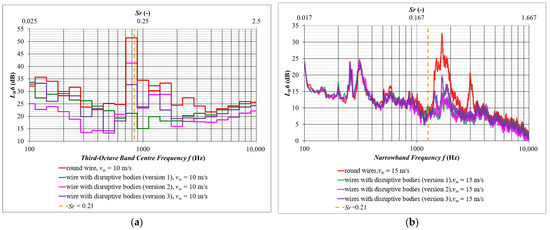
Figure 12.
Numerical and experimental results for round wires with disruptive surface bodies in the wind tunnel: (a) comparison of simulated third-octave band spectra of LW6 at v∞ = 10 m/s and (b) comparison of experimentally measured narrow-band spectra of LW6 at v∞ = 15 m/s.
Experimental validation at v∞ = 15 m/s yielded comparable results, as shown in Figure 12b. Measurements at 10 m/s were not suitable due to the dominant self-noise of the wind tunnel, and simulations at higher velocities are pending. In the experiments, the modified wires were again printed using resin and installed as an array of nine equally spaced elements. The measured narrowband spectra confirm the simulated trend: disruptive elements reduced the primary vortex shedding tone (at approximately 1600 Hz) by 10–20 dB and the second harmonic (around 3000 Hz) by approximately 10 dB. Low-frequency tones (250–300 Hz), attributed to wind tunnel self-noise, are considered irrelevant for this analysis.
Interestingly, the experimental ranking of geometries differed slightly from simulation results. The wire variant with fewer but larger surface protrusions (Version 2) yielded the best noise reduction in the measurements. This deviation may stem from limitations in the simulation mesh resolution, which might not fully capture the flow interactions with the fine surface structures. Due to the substantial computational cost, further mesh refinement was not pursued.
For the wires with disruptive bodies, the von Kármán vortex street is still clearly observable, as visualized in Figure 13a, albeit in a less homogeneous and less symmetrical form compared to the reference wire. The vorticity magnitude on a horizontal plane through the wire axis, shown in Figure 13b, illustrates that the vortex shedding becomes notably more irregular and less coherent along the longitudinal direction of the wire due to the presence of disruptive bodies on its surface. This reduction in spatial coherence is considered to be the primary mechanism behind the observed decrease in noise emission.
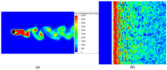
Figure 13.
Simulation results for a single wire with a diameter of Dwire = 2.5 mm and surface-mounted disruptive bodies (Version 1) at an upstream velocity of v∞ = 10 m/s: vorticity magnitude on a plane perpendicular to the wire axis (a), and on a longitudinal plane through the wire axis (b).
4.2. Experimental Investigation of Surface-Treated Steel Wires
The industrial realization of wires with discrete disruptive bodies, as employed in previous prototype studies, presents significant manufacturing challenges and cost implications. To address this, an alternative approach involves generating a roughened surface by embedding or attaching small particles—such as sand—into the coating layer of steel wires. In the present study, several wire specimens were fabricated by applying sand of varying grain sizes and quantities to a wet coating layer. Figure 14 presents magnified images of representative samples produced using this technique. For these samples sand with grain size [0.3–0.6] mm was used. Acoustic measurements conducted with these surface-treated steel wires confirm the beneficial effect of the surface irregularities (Figure 15). Compared to smooth round steel wires (Figure 15a), the treated wires exhibit a noticeable reduction in overall sound power level LW6 across the entire range of upstream velocities tested. While the prototypes fabricated via resin printing achieved superior attenuation at higher velocities (v∞ ≥ 15 m/s), the surface-treated steel wires still show significant noise mitigation. Specifically, the narrow-band spectra at v∞ =15 m/s reveal a substantial reduction in the tonal peak associated with the vortex shedding frequency and its second harmonic (Figure 15b). Notably, noise emissions at other frequencies remain largely unaffected.

Figure 14.
Surface-treated round steel wires: microscopic images showing sand particles (grain size [0.3–0.6] mm) embedded in the coating layer to create a roughened, acoustically disruptive surface: (a) wire with a higher particle density; (b) wire with a lower particle density.
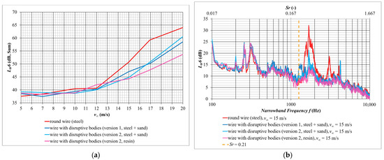
Figure 15.
Experimental results for round steel wires with a diameter of Dwire = 2.5 mm featuring surface-mounted disruptive bodies (sand): (a) overall pressure-side sound power level LW6 as a function of upstream velocity v∞; (b) comparison of the corresponding narrow-band spectra of LW6 at v∞ = 15 m/s.
Further research is required to optimize parameters such as the grain size, density, and spatial distribution of the surface roughness elements. In Section 5, Optimization of a real Fan Guard Grille, this approach is extended to complete guard grilles, followed by a comprehensive assessment of their aerodynamic and acoustic performance in full-scale fan installations.
5. Optimization of a Real Fan Guard Grille
In the subsequent step, the optimized surface treatment was applied to an entire guard grille of an axial fan with a diameter of 630 mm. The corresponding acoustic measurements were conducted in the ZIEHL-ABEGG anechoic facility. Figure 16a displays the experimental setup with the axial fan equipped with the downstream-optimized guard grille. Analogous to the treatment of individual wire segments, sand was randomly distributed onto the wet coating of the grille to create a rough, acoustically disruptive surface Figure 16b. Systematic variation in the grain size and the treated areas revealed that sand with grain size of [0.6–1.2] mm applied on the outer region of the guard grille—highlighted in Figure 16c—has the most significant influence on the acoustic optimization. This indicates that the peripheral zones contribute disproportionately to the generation of tonal components and should therefore be prioritized in surface modification strategies.
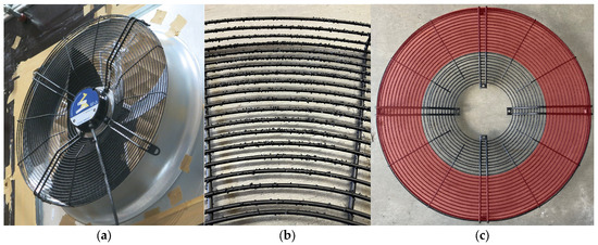
Figure 16.
(a) Experimental setup of the axial fan with downstream guard grille featuring disruptive surface treatment; (b) detailed view of the treated guard grille surface; and (c) identification of the critical outer region primarily responsible for acoustic optimization effects.
Figure 17a presents the dimensionless performance curve along with the sum of the specific A-weighted pressure side sound power level, LWA6spec, for an axial fan of diameter 630 mm equipped with a downstream guard grille featuring disruptive surface treatment, compared to a standard guard grille. Notably, at lower specific diameters (δ ≤ 1.4), the guard grille with disruptive bodies achieves a reduction in the sum of LWA6spec of up to 1.5 dB. However, this acoustic benefit is accompanied by a slight increase in pressure drop, leading to a reduction in maximum static pressure rise. It should be noted, however, that effects related to the operating point are fully incorporated in the specific A-weighted overall sound power level LWA6spec. The spectral analysis of LWA6spec at δ = 1.2, depicted in Figure 17b, confirms that the disruptive bodies significantly suppress the characteristic acoustic hump in the range of 700–1000 Hz—attributed to vortex shedding—by several decibels. These findings are in good agreement with the prior experimental investigations on isolated wire segments in the wind tunnel. Future work will focus on identifying the optimal configuration in terms of size, density, and placement of the disruptive elements to maximize noise reduction while minimizing aerodynamic penalties.
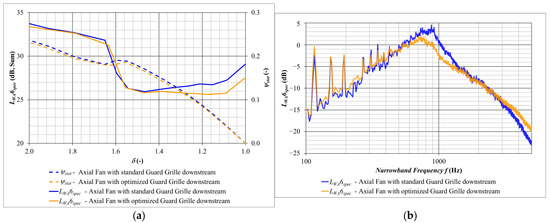
Figure 17.
Experimental results for an axial fan of size 630 mm equipped with a standard downstream guard grille (blue) and with a downstream guard grille featuring disruptive surface elements (orange): (a) specific A-weighted overall pressure side sound power level LWA6spec; and (b) corresponding spectral content at δ = 1.2.
6. Conclusions
In axial fan applications, the rotating components must often be protected by a guard grille, typically composed of wires with circular cross-section. Particularly for modern axial fans designed for low self-noise operation, these guard grilles can become significant—if not dominant—aeroacoustic noise sources. In the case studied, the installation of a downstream guard grille resulted in an increase in the A-weighted overall sound power level on the pressure side by up to 7 dB.
To investigate the underlying mechanisms of noise generation by wire-induced flow disturbances, both an experimental wind tunnel setup and a corresponding numerical model based on a Lattice-Boltzmann solver were developed. The observed spectral peaks in the experimental and simulated results align with the frequency ranges associated with increased noise emissions from guard grilles under comparable flow conditions. The unsteady flow simulations revealed that periodic vortex shedding (von Kármán vortex street) downstream of round wires contributes significantly to the emitted noise. Moreover, the vortex street appears highly homogeneous and coherent in the axial direction of the wires.
Subsequent simulations and measurements demonstrated that disrupting the coherence of the vortex shedding in the longitudinal direction—by introducing surface irregularities—leads to a marked reduction in sound emission at the vortex shedding frequency. One effective method involved applying small disruptive bodies to the wire surfaces. Experimental results showed that even a randomly distributed application of fine sand particles on the surface coating of steel wires led to substantial reductions in sound emissions.
Initial tests with a fully treated guard grille confirmed these findings, showing a clear reduction in sound power at the vortex shedding frequency, consistent with earlier wire-segment experiments.
It is particularly noteworthy that relatively simple surface modifications—such as the application of small disruptive elements—are effective in breaking the coherence of the vortex shedding structures. These interventions significantly reduce the sound emission at the critical shedding frequency and its harmonics without requiring fundamental changes to the overall grille geometry or wire layout. The approach is not only experimentally confirmed at the wire level but also scalable to a full fan installation.
Nonetheless, the acoustic benefit is accompanied by a measurable increase in aerodynamic resistance. This underlines the need for a careful balance between noise reduction and pressure performance. In practical applications, the trade-offs must be evaluated in the context of system requirements and regulatory constraints.
The findings open promising pathways for noise optimization of guard grilles in axial fans, but further work is needed to refine surface treatment techniques, explore long-term durability, and ensure cost-efficient manufacturability at industrial scale.
Author Contributions
Conceptualization, S.H. and F.L.; methodology, S.H. and F.L.; software, S.H.; validation, S.H.; investigation, S.H.; data curation, S.H.; writing—original draft preparation, S.H. and F.L.; writing—review and editing, S.H. and F.L.; visualization, S.H.; funding acquisition, F.L. All authors have read and agreed to the published version of the manuscript.
Funding
This research was funded by Bundesministerium für Wirtschaft und Energie—BMWE, grant number 03EN4065E.
Informed Consent Statement
Not applicable.
Data Availability Statement
The data presented in this study are available on request from the corresponding author due to privacy reasons.
Conflicts of Interest
The authors declare no conflicts of interest.
Abbreviations
The following variable symbols, units and definitions are used in this manuscript:
| D2 | (m) | outer diameter of the fan |
| Dwire | (m) | diameter of the wire |
| f | (Hz) | frequency |
| ftheo | (Hz) | theoretical vortex shedding frequency |
| ftheo,9wires | (Hz) | theoretical vortex shedding frequency with blockage of nine wires |
| fexp | (Hz) | experimentally measured frequency |
| fsim | (Hz) | simulated frequency |
| LW6 | (dB) | pressure side sound power level |
| LWA6 | (dB) | A-weighted pressure side sound power level |
| LW6spec | (dB) | specific pressure side sound power level |
| LWA6spec | (dB) | specific A-weighted pressure side sound power level |
| n | (rpm) | rotation speed of the impeller |
| p | (Pa) | pressure |
| QV | (m3/h) | volume flow rate |
| Re | (-) | Reynolds number |
| Sr = f Dwire/v∞ | (-) | Strouhal number |
| u2 | (m/s) | circumferential velocity |
| v∞ | (m/s) | free-stream velocity |
| δ | (-) | specific diameter |
| φ | (-) | dimensionless volume flow rate |
| ρ | (kg/m3) | density |
| ψstat | (-) | dimensionless static pressure rise |
References
- Eck, B. Ventilatoren, 6th ed.; Springer Verlag: Berlin/Heidelberg, Germany, 2003; pp. 9–14. [Google Scholar]
- Schneider, M.; Lucius, A.; Pazhanisamy, R. Einfluss von Schutzgittern auf die Akustik von Axialventilatoren. In Proceedings of the DAGA—Jahrestagung für Akustik, Wien, Austria, 15–18 August 2021. [Google Scholar]
- Kármán, T.v. Über den Mechanismus des Widerstandes, den ein bewegter Körper in einer Flüssigkeit erzeugt. Nachr. Ges. Wiss. Göttingen, Math. Phys. Klasse 1911, 1911, 509–517. Available online: https://eudml.org/doc/58812 (accessed on 26 November 2024).
- Strouhal, V. Über eine besondere Art der Tonerregung. Ann. Phys. 1878, 241, 216–251. [Google Scholar] [CrossRef]
- Henn, H.; Sinambari, G.R.; Fallen; M. Ingenieurakustik, 4th ed.; überarbeitete und erweiterte Auflage; Vieweg+Teubner: Wiesbaden, Germany, 2008; p. 170. [Google Scholar]
- Schlichting, H.; Gersten, K. Grenzschicht-Theorie, 10th ed.; überarbeitete Auflage; Springer Verlag: Berlin/Heidelberg, Germany, 2006; p. 19. [Google Scholar]
- Blevins, R.D. Review of Sound induced by Vortex Shedding from Cylinders. J. Sound Vib. 1984, 92, 455–470. [Google Scholar] [CrossRef]
- Moreau, D.J.; Doolan, C.J. On the sound produced by flow interaction with a wall mounted finite length cylinder. In Proceedings of the Acoustics 2012: Annual Conference of the Australian Acoustical Society, Fremantle, Australia, 21–23 November 2012. [Google Scholar]
- Zdravkovich, M.M. Flow induced oscillations of two interfering circular cylinders. J. Sound Vib. 1985, 101, 511–521. [Google Scholar] [CrossRef]
- Hutcheson, F.V.; Brooks, T.F. Noise radiation from single and multiple rod configurations. Int. J. Aeroacoustics 2012, 11, 291–333. [Google Scholar] [CrossRef]
- Geyer, T.F.; Abromeit, P.; Prügel, M. Noise generation by tandem cylinders of different diameter in cross-flow. In Proceedings of the DAS/DAGA 2025—51st Annual Meeting on Acoustics, Copenhagen, Denmark, 17–20 March 2025. [Google Scholar]
- Geyer, T.F. Experimental evaluation of cylinder vortex shedding noise reduction using porous material. Exp. Fluids 2020, 61, 153. [Google Scholar] [CrossRef]
- Li, T.; Lu, N. Numerical investigation on noise and flow characteristics of a circular cylinder with helical grooves. Discov. Appl. Sci. 2025, 7, 699. [Google Scholar] [CrossRef]
- Jia, W.; Xu, H. Vortex shedding suppression in elliptical cylinder via reinforcement learning. arXiv 2025, arXiv:2410.00421v2. [Google Scholar] [CrossRef]
- DIN EN ISO 3745; Akustik—Bestimmung der Schallleistungspegel von Geräuschquellen aus Schalldruckmessungen—Verfahren der Genauigkeitsklasse 1 für Reflexionsarme Räume und Halbräume. DIN Deutsches Institut für Normung e.V.: Berlin, Germany, 2017. [CrossRef]
- ISO 13347-3; Industrial Fans—Determination of Fan Sound Power Levels Under Standardized Laboratory Conditions—Part 3: Enveloping Surface Methods. International Organization for Standardization: Geneva, Switzerland, 2004.
- Chen, S.; Doolen, G.D. Lattice Boltzmann method for Fluid Flow. Annu. Rev. Fluid Mech. 1998, 30, 329–364. [Google Scholar] [CrossRef]
- Marié, S. Etude de la Méthode Boltzmann sur Réseau Pour les Simulations en Aéroacoustique. Ph.D. Thesis, Université Pierre et Marie Curie, Paris, France, 2008. [Google Scholar]
- Chen, H.; Filippova, O.; Hoch, J.; Molvig, K.; Shock, R.; Teixeira, C.; Zhang, R. Grid refinement in Lattice Boltzmann methods based on Volumetric Formulation. Phys. A Stat. Mech. Its Appl. 2006, 362, 158–167. [Google Scholar] [CrossRef]
- DBZ Deutsche Bauzeitschrift—Thyssenkrupp Testturm, Rottweil. Available online: https://www.dbz.de/artikel/thyssenkrupp-testturm-rottweil-3156533.html (accessed on 26 November 2024).
- SKI Consult—Wirbelerregte Querschwingung. Available online: https://ski-consult.de/taetigkeitsbreiche/strukturanalysen/wirbelerregte-querschwingung/ (accessed on 26 November 2024).
Disclaimer/Publisher’s Note: The statements, opinions and data contained in all publications are solely those of the individual author(s) and contributor(s) and not of MDPI and/or the editor(s). MDPI and/or the editor(s) disclaim responsibility for any injury to people or property resulting from any ideas, methods, instructions or products referred to in the content. |
© 2025 by the authors. Published by MDPI on behalf of the EUROTURBO. Licensee MDPI, Basel, Switzerland. This article is an open access article distributed under the terms and conditions of the Creative Commons Attribution (CC BY-NC-ND) license (https://creativecommons.org/licenses/by-nc-nd/4.0/).