Abstract
This paper presents an analysis of the stability margin improvement (SMI), which is also known as stall margin improvement, achieved by continuous tip air injection. New piezoelectric actuators were designed and manufactured with a new engine inlet for the Larzac 04 C5 jet engine. It has noninvasive injection positions that do not have any measurable effect on the inlet air flow when it is switched off. The main focus of the system design was to achieve high power of the injected air and, as a result, a high SMI. The results presented enable a maximum SMI of 99%. A variety of engine operating conditions and injection positions were experimentally tested and discussed regarding SMI. Additionally, the complex relationship between SMI gains and thrust specific fuel consumption (TSFC) is explored in a power balance analysis, revealing a trade-off between SMI improvement and increased energy consumption.
1. Introduction
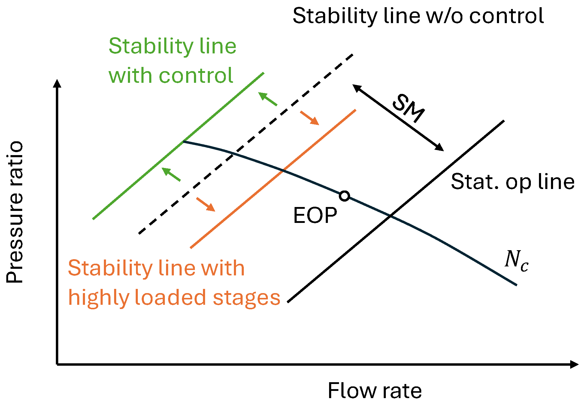
The design of axial compressors for turbofan engines is driven by the demand for improved performance and efficiency, particularly in achieving a high thrust-to-weight ratio. This ratio is a critical factor in modern aviation, as it directly influences an aircraft’s payload capacity, fuel efficiency and overall operational performance. To achieve this, the Overall Pressure Ratio (OPR) of the engine must also be maximized, as a higher OPR contributes to improved thermodynamic efficiency and reduced specific fuel consumption. However, these advancements place greater demands on the compressor design, requiring higher blade loading and subjecting the internal flow to stronger pressure gradients. This, in turn, challenges the flow stability of the compressor system and reduces the Stability Margin (SM), as illustrated in Figure 1. This is also known as the Surge Margin. Depending on the flight condition, the Engine Operating Point (EOP) can shift along the speed line towards lower mass flow rates and higher pressure ratios. If the stability line is reached, a rotating stall and/or surge occur and can inflict drastic damage on the complete engine system, resulting in loss of thrust. According to this, many efforts have been made for decades to increase compressor flow stability and have resulted in the development of control techniques to shift the surge line and increase the SM again, see Figure 1.
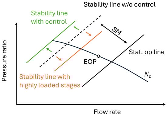
Figure 1.
Schematic shift of the stability line due to highly loaded stages and control mechanisms.
The closer the EOP gets to the stability line, the more the compressor is throttled, and the incidence angle at the blade increases. The larger the incidence angle, the larger the flow turning on the profile until a separation occurs on the suction side of the blade. Close to the stability line, various aerodynamic phenomena overlap. Based on the results of Day [1] the flow in most axial compressors and most jet engines has a spike-type inception. The original definition of spikes assumes the formation of a separation on the suction side as a result of a local change in angle of incidence at the blade tip leading edge [2,3]. As a result of that, the control mechanisms have to affect the flow in the blade tip region.
Hathaway [4] has summarized various passive casing treatments, such as honeycombs and circumferential grooves with varying geometries. However, these passive control techniques are often associated with efficiency penalties that do not meet the high efficiency demands of modern aircraft engines [5]. Therefore, active systems are developed to only influence the flow when required. A technology that is used for actively promoting stability is tip air injection. Due to the injection of high energy flow, the relative flow angle (incidence angle) at the blade tip is affected, and the relative velocity increases. This suppresses the occurrence of disturbances and ensures that the flow is reattached to the suction side of the blade. The first-known idea for this technique dates back to 1950 [6]. The positive mechanism of tip air injection could be demonstrated by Epstein, Greizer et al. [7] and Day [1], who were able to extend the operating limit of a compressor by air injection. According to Suder et al. [8] air injection at the tip can improve the stability limit, particularly in tip-critical rotors. This was also confirmed by Freeman et al. [9] who further validated this method on a Viper engine.
Similarly, or even better, the results are validated on subsonic compressor rigs, where the SM was doubled [10]. However, Wang et al. [11] shows that the effect also achieves good results on transonic running compressors, but these are lower than on subsonic compressor test benches. In the field of transonic compressors, various research groups have explored setups with different numbers of injection positions. Suder et al. [8], in their study of a high-speed transonic compressor with constant injection, found that a large number of injection positions was not necessary. In their experiments, the increase in stability margin improvement beyond four injection positions was minimal. Adding more injection positions slightly extended the operating range but led to a disproportionately higher increase in the injected mass flow rate, ultimately reducing overall efficiency. From these studies, Suder concluded that the velocity or mass flow at each individual injection position plays a more crucial role than simply increasing the number of injection points. Supporting this, numerical investigations by Beheshti et al. [12] demonstrated that narrower nozzles with higher velocities resulted in a better operating range expansion. On a multi-stage transonic compressor, Li et al. [13] shifted the instability behavior from the first to the second due to the tip air injection. Kefalakis and Papailiou [14], working on a test rig based on the first stage of the Larzac 04 Low-Pressure Compressor (LPC), confirmed that fewer injection positions at lower air mass flows produced a greater relative improvement in operating range. However, when more injection positions were used, they observed an overall increase in mass flow rate, which significantly extended the compressor’s operating limit. This finding is critical for the efficiency of a closed system in aircraft engines.
Also, the Institute of Jet Propulsion (IJP) at the University of the Bundeswehr Munich validated the performance of tip injection on a Larzac 04 C5 turbofan [15,16,17,18,19]. A high stability margin improvement was presented by Stößel [20]. However, the invasive design is disadvantageous when switched off. For this reason, Kern [21] developed an injection system with a non-invasive design that positively influences the operating limit. In his investigations [17], he found that the positive influences on the stability limit depend on the injected mass flow multiplied by the injected velocity squared, which is defined as the power of injection in this paper:
This leads to two questions of this work:
- Q1: How three parameters, the velocity, the mass flow, and the power of the injection, affect the SMI?
- Q2: Are fewer injection positions better in terms of SMI and overall power balance?
2. Larzac 04 C5
The Larzac 04 C5 has already proven its suitability for active stability control via tip air injection several times [15,16,17,18,19] and was, therefore, used in the tests for this paper. The Larzac 04 C5 is a twin-shaft turbofan engine designed for the Alpha Jet [22]. The design of the engine in the C5 configuration is shown in Figure 2. A two-stage LPC provides compression with a total pressure ratio of 2.26. Downstream, the fluid is divided into bypass and the core with a Bypass ratio (BPR) of 1.13. The bypass and core mass flows are discharged through separate nozzles, which provide conditions particularly suitable for the study of active injection, which will be discussed in more detail in the next section. The main performance and geometry data of the Larzac 04 C5 are summarized in Table 1.
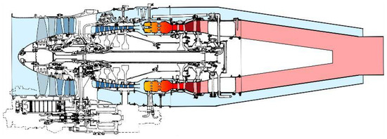
Figure 2.
Sectional view of the Larzac 04 C5 engine [23].

Table 1.
Design Performance data of the Larzac 04 C5 jet engine [19].
The focus of this work is the Larzac 04 C5 LPC, which, unlike other military engines, does not use an IGV. The rotor has 23 blades in the first stage and 29 blades in the second stage. Both rotors are subjected to transonic blade tip inflow conditions in the relative frame of reference and have a design Mach number at the tip of 1.37 for the first stage and 1.22 for the second stage. This design is similar to modern standards and allows a higher stage pressure ratio compared to subsonic compressors. However, this requires a blade tip profile geometry that does not cause excessive flow loss at high Mach numbers, but takes advantage of the compression of the resulting shocks.
A unique feature of the Larzac 045C is the inlet adapter, which connects the inlet to the LPC. This is designed as a separate component and can be removed without mechanical intervention in the compressor. This makes it possible to install test rigs, like an AFC, only less than 30 mm in front of the blade leading edge. To make air injection tests independent of external air sources, high-pressure air can be supplied from the engine through the bleed air ports. These are located in the stator of the fourth stage of the HPC, just before the combustion chamber. Tests on the IJP have shown that approximately 2% of the inlet air mass flow can be extracted in this way [24].
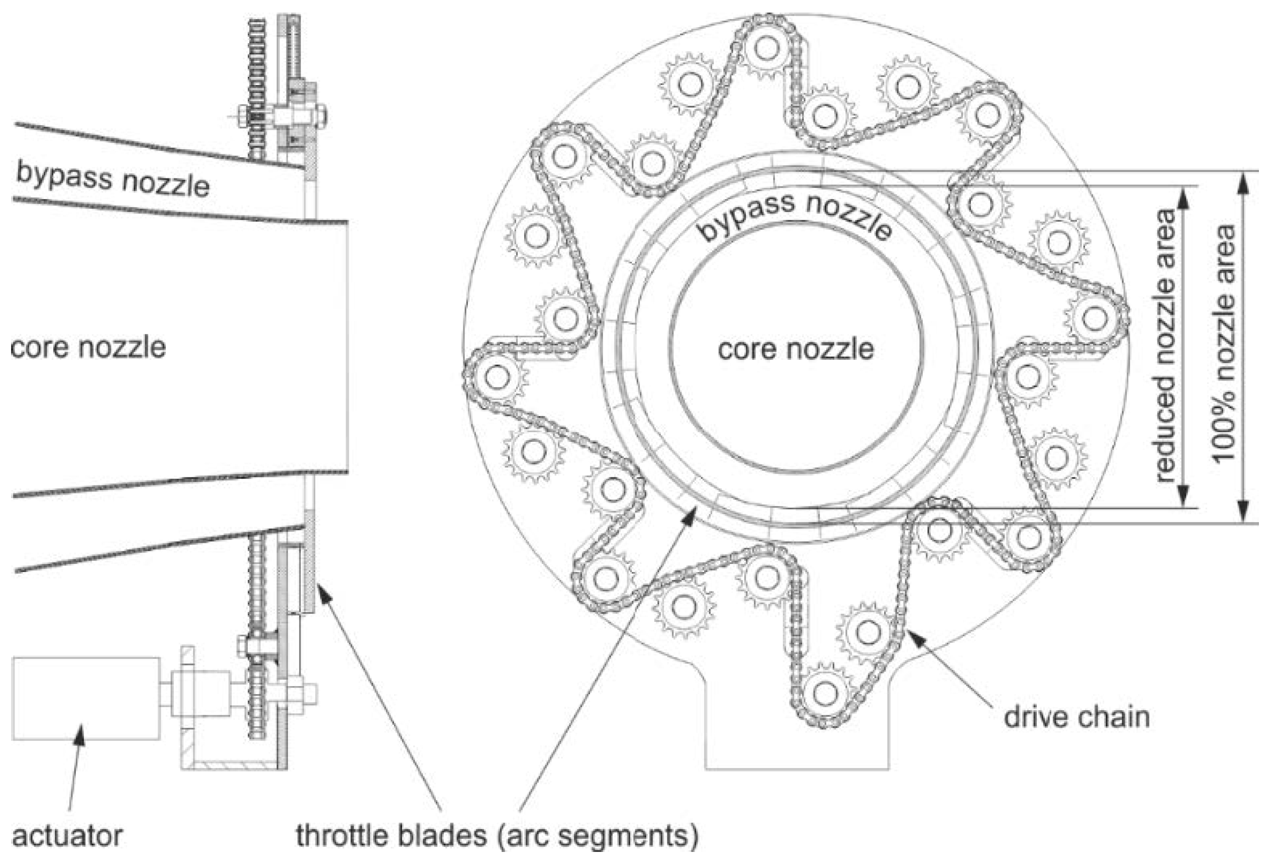
To evaluate the effectiveness of air injection, flow instabilities must be induced in the LPC. To conduct that, the above-mentioned nozzle configuration with separate bypass and core outlets is advantageous, because it allows the low-pressure compressor to be throttled independently of the HPC. To throttle the LPC, a bypass throttle device was installed on the Larzac 04 C5, shown in Figure 3. It consists of multiple throttle sections that reduce the nozzle exit area from 100% to a minimum of 10%. This setup allows exceeding the stability limit in a controlled way and thus to measure the characteristics of the Larzac 04 C5 LPC in a reproducible way.

Figure 3.
The bypass nozzle of the Larzac 04 C5 engine [23].
The loads resulting from the flow separation induce extreme loads to the compressor blade, so that such tests are only possible due to the robust design of the engine and, in particular, of the LPC. To avoid imminent damage to the test vehicle, the stability limit was not approached at more than corrected speed. Rotor 1 of the compressor is already operating in the transonic range at , so all relevant flow phenomena are already present at 90% and the full function of the active injection can be demonstrated.
3. Experimental Setup
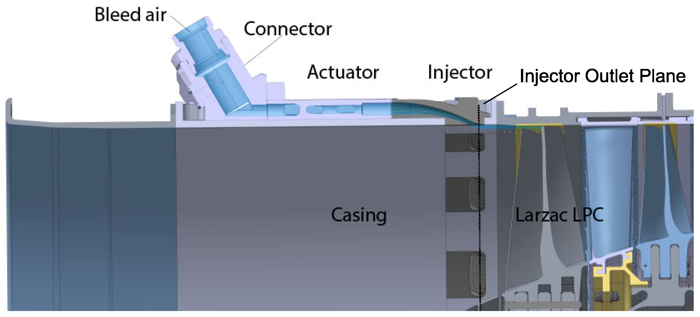
Based on the knowledge gained on injection systems at IJP through former studies in this field of research, the power of the injection should be maximized in the new setup to gain the highest possible and most efficient SMI [17]. Separate (discrete) injection positions can generate more power of the injection with the available mass flow. To control the mass flow to be injected, the actuators described in Section 3.1 are used in a non-invasive design. In order to install these actuators directly upstream of the rotor of the first stage of the Larzac 04 C5, a new casing and injector were designed and manufactured. A sectional view shows the arrangement of the AFC system and the LPC of the Larzac 04 C5, see Figure 4. This injection system uses the Coandă-effect to align the injected flow with the casing wall. By using the Coandă-radius, the streamlines follow the wall contour and the airflow reaches the blade tip region at high velocity. The Coandă-effect inside injection systems is already used by Strazisar et al. [25] and Kern et al. [21].
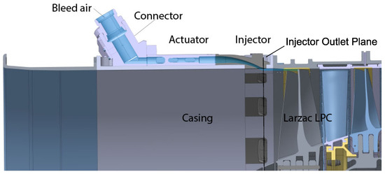
Figure 4.
Sectional view of one injection position inside the new AFC-System and the Larzac 045C LPC adapted from [26].
The bleed air of the Larzac 04 C5 engine is connected to special connectors which are installed upstream of the actuator (valve), see Figure 4. Downstream of that, the injector with its Coandă-radius is located. The final design of the new AFC system consists of 17 actuators and 17 injectors and a casing on which they are installed, which was developed as part of the ACONIT-project [27]. The number of discrete ports is a compromise of available installation space, maximizing mass flow and design constraints for the actuator system. The AFC system is installed directly in front of the Larzac 04 C5 fan rotor at the test bed of the Institute of Jet Propulsion (ground test conditions), as presented in Figure 5. Further information on experimental setup can be found in the ACONIT Report [28,29].
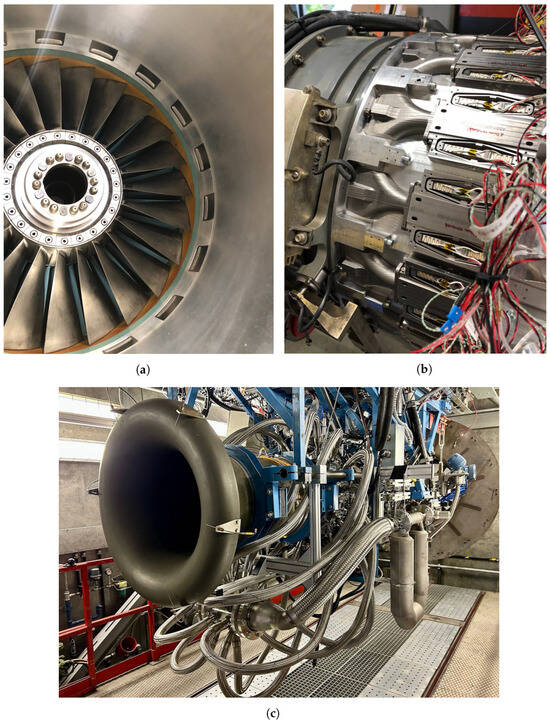
Figure 5.
Experimental test setup on the Larzac 04 C5 engine. (a) AFC inner inlet view w/o spinner [30]. (b) Actuators and injectors installed into the casing. (c) Final test setup installed into the test bed [31].
3.1. Piezoelectric Actuator
The Pulsed Jet Actuator (PJA), referred to as the actuator in the following, is designed by Cedrat Technologies (Meylan, France) and operates based on piezoelectric principles. Piezoelectric materials rapidly expand when a voltage is applied, making them the key component of the actuator. The role of this actuator is to be a fast valve with a really low response time. This valve is normally closed without any voltage and completely opened at the full voltage of 150 V. The objective is to have the valve completely closed in normal conditions and to have the valve completely open when the flow needs to be controlled. The actuator was designed to meet several requirements to be operated with the engine. First, about the fluidic parameters, the actuator must reach a mass flow of 30 g/s and must work with a relative pressure up to Pa. In addition, the desired working frequency ranges from continuous opening to 200 Hz pulsed. About the thermal aspects, the actuator should work with hot, pressurized air, coming from the engine, at a maximum temperature of 330 °C. Furthermore, the actuator must withstand engine vibrations. Finally, the actuator needs a time response for initial opening close to 1 millisecond. This fast time response is one of the reasons for the piezoelectric choice for the AFC application in the Larzac 04 C5 engine.
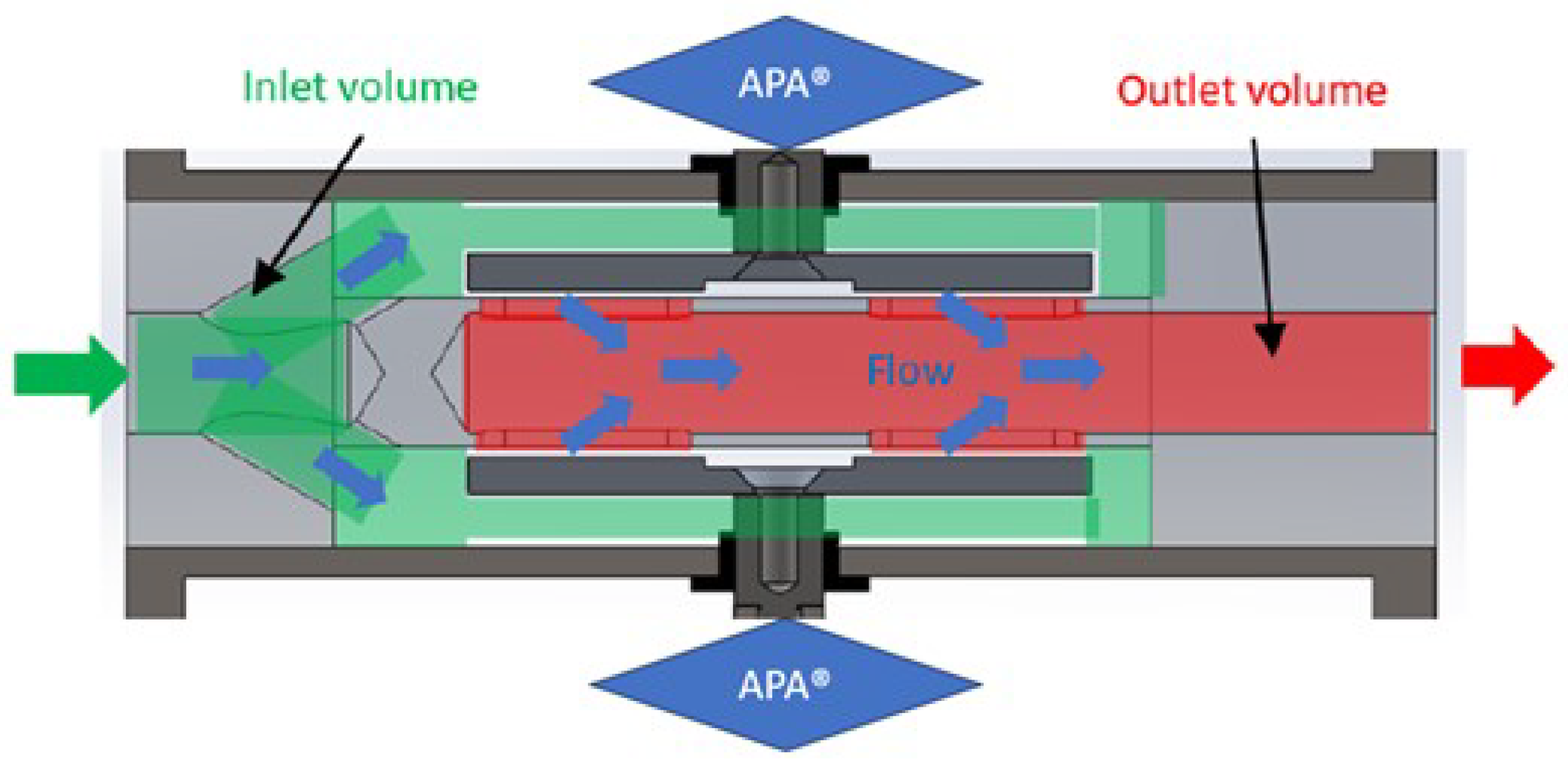
The final actuator consists of a piezoelectric active system that functions as a PWM (Pulse Width Modulation) valve, including the piezoelectric actuators, called APA® and a passive system, including the injector used to optimize the flow. In detail, the active system is composed of two customized APA400MML® working in parallel (Figure 6). The role of these piezoelectric actuators is to open/close two valves, see Figure 7 in gray. The APA400MMLs are positioned in parallel to the flow and expand under electrical voltage. This force expands the frame of the APA400MML and thus opens up the flow path within the actuator. The maximal gap inside the valve is 300 µm on both sides and can be controlled up to 200 Hz (square on/off modulation). The APA400MML® is customized because the interfaces were modified and it is thermally compensated to limit the impact of the thermal evolution on the performances. Indeed, the work of optimization to limit the effects of the thermal expansion allowed to reduce the Coefficient of Thermal Expansion (CTE) of the APA® from 145 ppm/K to 38 ppm/K. This reduction is limiting the impact of the temperature on the leakage when the valves are closed.
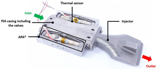
Figure 6.
Overview of the pulsed jet actuator with an attached injector.

Figure 7.
Detail of the valves inside the pulsed jet actuator (in open configuration).
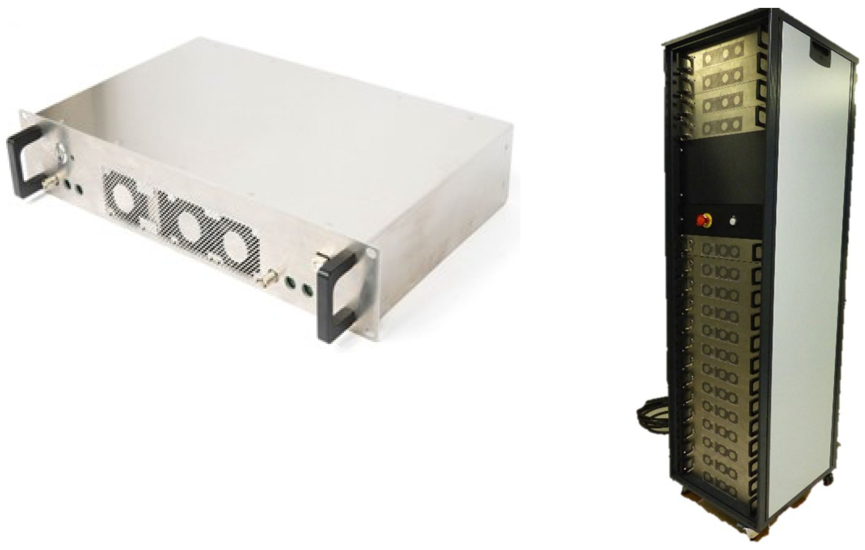
The actuators are driven by 17 independent piezoelectric linear amplifiers, called PLA25® see Figure 8. This has many advantages in terms of controlling each separately, for example, for a mass flow calibration.
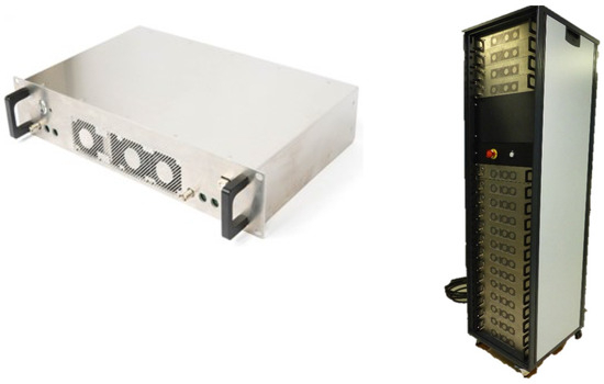
Figure 8.
New PLA25 (left) and final version of the cabinet (containing 17 PLA25®) used to drive the 17 actuators (right).
Downstream of the actuator, the injector is located, see Figure 6. Since the geometry of the injector cannot be varied in the setup, the injection velocity is primarily determined by the injected mass flow and input conditions of the air entering the AFC system. The injector geometry is designed for an injection mass flow of 30 g/s, resulting in 0.5 kg/s when all actuators are active, which the Larzac 04 C5 reaches at . However, if the injection mass flow is reduced, the flow velocity of the injected mass flow will decrease.
3.2. Measurement Equipment
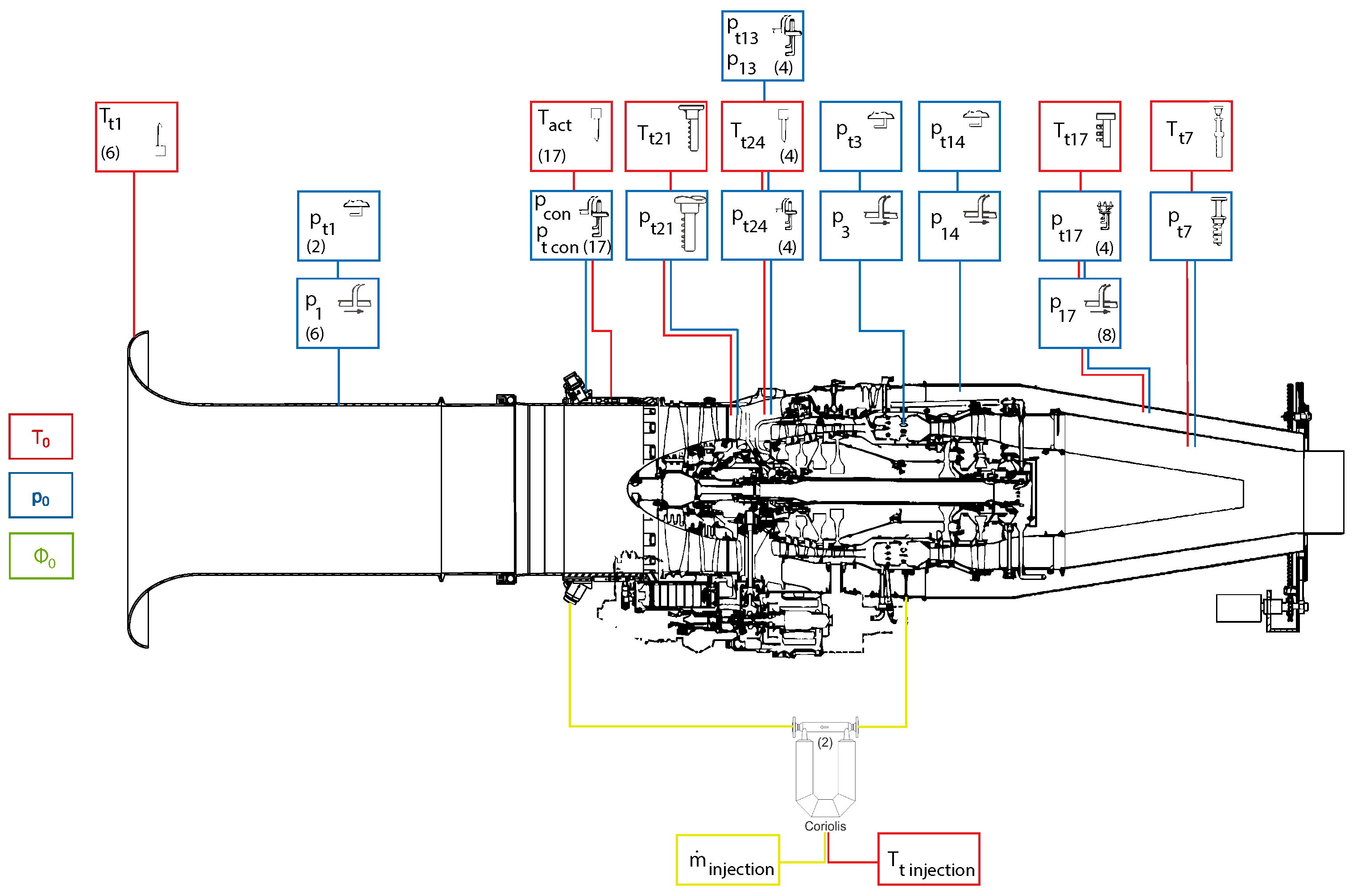
Besides the regular performance and operation surveillance instrumentation such as spool speed, fuel flow, thrust, etc., the Larzac 04 test vehicle comprises extensive instrumentation at the LPC, which is shown in Figure 9. The red markers indicate the positions of temperature probes, the blue markers represent pressure measuring probes and the yellow markers show the mass flow measurement points. The number in brackets indicates the number of equivalent positions in the test vehicle. To adjust the variables to ISA standard conditions, ambient temperature, ambient pressure and humidity were recorded and used to calculate the corrected values. The bleed air mass flow rate and temperature are determined using two Coriolis flow meters located just after the bleed air leaves the HPC. In addition to the previously mentioned instrumentation, the Larzac 04 C5 was equipped with instrumented stator vanes featuring pressure probes. These probes provided detailed information on the radial flow differences downstream of the rotors. Additionally, a high-frequency measurement system with piezoelectric pressure transducers from Kulite was used. These transducers are described in detail by Kern et al. [23] and are documented in the ACONIT Report [32].
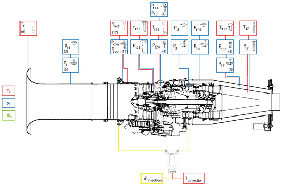
Figure 9.
Global measurement position on the Larzac 04 C5 engine [28] based on [17].
3.3. Method
All tests were carried out applying the same procedures. During the tests, various engine operating points (EOP) of the LPC were approached, using the corrected LPC spool speed () and the bypass throttle as control variables. The throttle controls the back pressure and thus the position of the EOP between the steady-state operating line and the stability limit.
Both steady-state and transient tests were performed. In steady-state tests, a specific EOP is held constant for 10 s with the throttle fully open. Transient tests involve a change in the EOP (throttle closing) while the data are being recorded. For this purpose, the bypass throttle is closed slowly until the stability limit is exceeded and then opened quickly to avoid unnecessary loads on the test vehicle. For the Larzac 04 C5, the corrected LPC spool speeds of 54%, 76%, 81% and 90% are of particular interest and, in accordance with the previous work, are focused on here. At 54% corrected speed, the relative velocity at the rotor tip is still well below Ma = 1. At 76%, the relative velocity at the rotor tip of the first compressor stage approaches Mach 1, leading to the formation of localized supersonic flow segments along the blades and within the passages. Consequently, the passage flow in the tip region becomes fully supersonic at 81% and 90% corrected speeds.
After the test without injection, the tests with injection were performed. In this test, the injection is already active at the stable operating line and the throttling of the engine is conducted in the same way as in the test without injection. This paper focuses on two configurations, differing in the number of injection positions utilized. Depending on the variation of how many injectors are active, the cases for this paper with eight active positions are called eight jets and the case with all injection positions active is called 17 jets. To evaluate the effect of the injection, the stall margin improvement is used. To differentiate it from the stall and surge mechanisms, it is called stability margin improvement (SMI) in this paper and the definition by Weigl et al. [33] is used. First, the stability margin (SM) is determined using the pressure ratio () and the mass flow for the stationary operating point (ref) and the point at the Stability Line (SL) as follows:
The potential stability margin is defined once for the case without injection (Baseline) and once for the case with injection. This results in the stability margin improvement as follows:
By defining the SMI, a statement can be made about the performance of the injection system.
- SMI Influencing factors
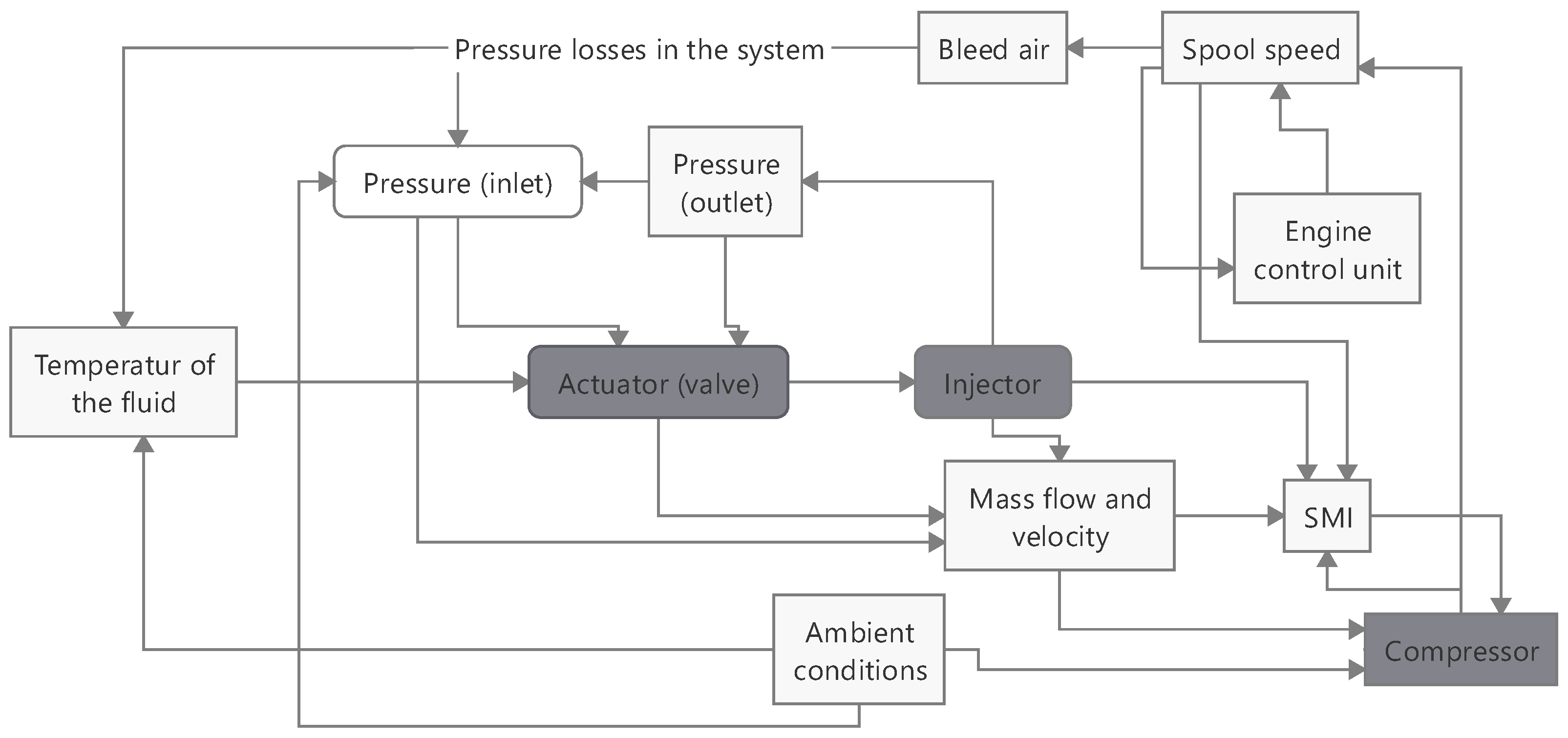
Unlike in a controlled test rig, where parameters can be adjusted individually, using bleed air does not allow the independent variation of parameters like pressure and mass flow. By using bleed air, many different factors have an influence on the change in the SMI. This is illustrated by Figure 10. The hardware components are highlighted in gray, and the flow components in white. For example, the spool speed has an influence on the bleed air mass flow. This, in turn, has an influence on the pressure losses in the system. This leads to speed-dependent temperatures and pressure upstream of the actuator. Depending on the temperature, the gap width of the actuator changes, which consecutively changes the mass flow. The pressure also has an influence on the air mass flow to be passed through. Depending on the mass flow, the downstream injector creates a back pressure for the actuator, which changes the pressure difference in the actuator, and therefore, the mass flow. All of this has an influence on the SMI and the compressor, which in turn, has an influence on the spool speed. Subsequently, the spool speed, in turn, has an influence on the engine control unit, as this regulates the fuel mass flow depending on the speed and thus changes the speed.
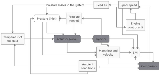
Figure 10.
Visualization of different factors of the AFC on the SMI.
4. Experimental Results
Before starting to compare the results, it is important to distinguish between values per jet and the global values across all jets. For example, at the mass flow of eight jets is higher per injector than in the configuration with 17 jets (see Table 2). However, the total mass flow, considering the sum of all jets, is larger in the 17-jet configuration. Due to the fact that the total system is self-regulating, for a given spool speed, the mass flow regulates itself due to pressure losses in the system of the bleed air; only the actuators regulate the start or stop (open and close) of the injection.
Table 2.
Mass flow and power of the injection for different jets and spool speeds.
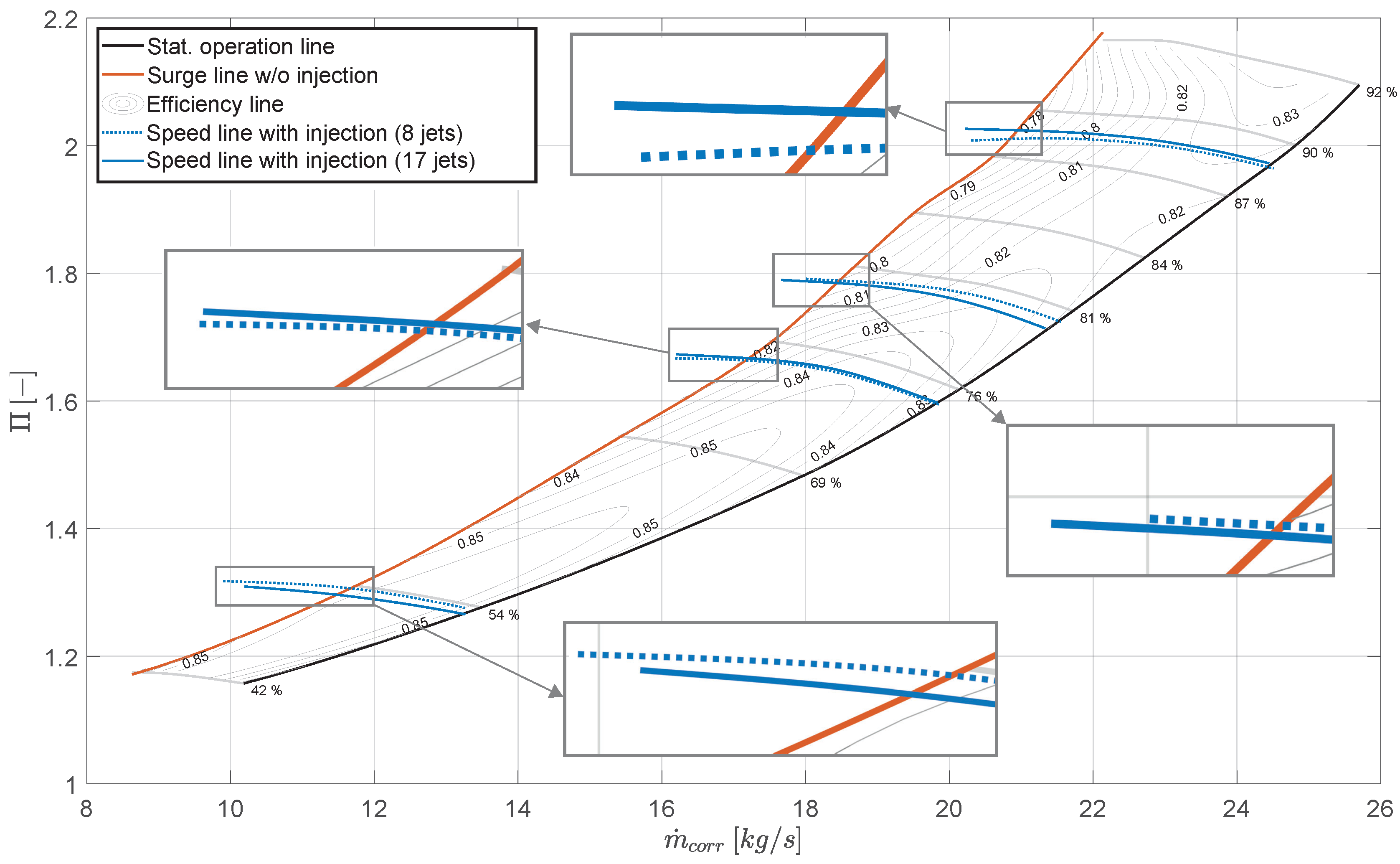
First, the SMI at different spool speeds will be considered and later the comparison at the same speed will be conducted. Therefore, the effects of the injection with regard to the SMI can be demonstrated well in the Larzac 04 C5 fan map, see Figure 11. In this figure, the stability line without injection is printed in orange, while the speed lines with injection are shown in blue. The results with eight jets are printed in a dashed line and the results with 17 jets are printed in a solid line. It is clearly seen that many stable EOPs are left of the stability line without injection. Taking the definition of SMI (see Equation (3)), in all cases with injection, an improvement is observed. The highest SMI, no matter with 8 or 17 jets, occurs at an operating point of , but as the LPC spool speed increases, the SMI decreases. These findings are consistent with previous studies, which have also reported higher SMIs at mid-speed levels and lower SMIs at high speeds [8,20].
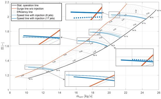
Figure 11.
Fan map of the setup with 8 and 17 jets.
Suder et al. [8] attribute this to the choking velocity of the injector in their setup, which is fixed and independent of compressor speed. As spool speed increases, the inlet velocity rises, reducing the velocity difference, which in turn, affects the SMI.
However, on the Larzac engine, the velocity at the Injector Outlet Plane (IOP) increases with rising spool speed, driven by the higher bleed air pressure. As a result, the injection Mach number increases even further compared to the axial inlet Mach number. For example, at with 17 jets, the axial Mach number difference between the injected Mach number at the IOP () and the intake Mach number () is . This value is lower than the difference observed at (), see Table 2. Notably, the velocity corresponds directly to the Mach number. Yet, despite the greater velocity difference at the higher spool speed, the SMI is notably lower. The same effect is observed for the configuration with eight jets, which contradicts the initial hypothesis proposed by Suder et al. [8].
All of these previous parameters refer to the injector plane, located approximately 30 mm upstream of the Leading Edge (LE). However, the critical area for analysis is the blade tip region. In this region, the relative Mach number is determined by the superposition of axial and circumferential velocities, both of which increase with higher spool speeds. Depending on the extent of these increases, the incidence angle at the blade tip also changes. For the Larzac engine, the exact Mach numbers directly in front of the LE are not known. However, assuming that the reduction in at the same spool speeds follows a similar proportional trend and by comparing the change in incidence between cases with injection of eight jets at and , it can be estimated that the change in incidence angle () caused by the increased axial velocity at the same spool speed is approximately . The positive change in the incidence angle indicates that the compressor’s throttling capacity is limited, as the deflection angle becomes excessively large even at low throttling levels. This observation provides a plausible explanation for the reduced SMI observed at higher spool speeds. But for 17 jets, the incidence angle between the spools’ speeds remains relatively unchanged across the first three speed lines and only shows a slight variation () at and the SMI also decreases with higher spool speeds. This suggests that other factors may be contributing to the observed decrease in SMI. To better understand the influence of the mass flow, the Mach number of the injection and the power of the injection, each spool speed will be investigated separately in the following.
- SMI on the same spool speed
With reference to the Larzac fan map (see Figure 11), it can be observed that the SMI varies between configurations with eight and 17 jets.
At a spool speed of , the configuration with eight jets achieves a higher SMI. Analyzing the mass flow per jet (), the Mach number at the injector outlet () and the power of injection per jet (), all these values are higher for the eight-jet configuration, correlating with the higher SMI. This supports Hathaway’s [4] finding that maximizing the speed per injector is critical for generating a large SMI.
Similarly, the power of injection per jet, as described by Kern [17], is also greater for the eight-jet configuration, reinforcing his conclusion about the importance of high per-jet injection power. However, when considering the global power of injection, which sums the power of all jets, the total value is lower at . This observation diverges from Kern’s original suggestion [17] that global injection power directly correlates with SMI. Taking a look at Kern’s setup, which does not have discrete jets, this split up of the definition is not necessary. But using discrete ports, the relevance of the global values and per jet becomes crucial. This suggests that the power per jet is more significant than the sum of the power of the injection, a conclusion that aligns with the findings of Suder et al. [8].
At or above, the SMI for the case with 17 jets is always higher. But the mass flow, velocity and power of injection per jet are higher for the case with eight jets, which contrasts with the trend observed at the lower spool speed. At higher spool speeds, only the total power of injection is higher with 17 jets. This suggests that achieving the highest possible power of injection per jet does not necessarily lead to the highest SMI. Instead, it is crucial to consider both the number of jets (which its ) and sum of the power of the injection per jet. It appears that up to a certain ratio, the power per jet has a dominant effect on SMI. However, beyond this point, the total power becomes more significant. Based on the available data, this turning point occurs when the power per jet in the 17-jet configuration exceeds approximately two-thirds (66%) of the power per jet in the eight-jet configuration.
Focusing on the flow conditions in the blade tip region at , the Mach number at the Injector Outlet Plane () is approximately 0.3 times higher for the eight-jet configuration compared to the 17-jet case. This difference influences the relative flow angles in the blade tip region. For the eight-jet configuration, the relative angle is 9 degrees lower along the stable operating line at the same spool speed. A lower relative angle reduces the risk of flow separation on the blade surface, allowing the compressor to be throttled more before reaching stall. This extended throttling range results in a higher SMI for the eight-jet configuration compared to the 17-jet setup.
As spool speeds increase, the difference in () between the two configurations diminishes. Consequently, the relative angle differences in the blade tip region also decrease. This suggests that, beyond the effects of mass flow, Mach number and injection power, the relative angle in the blade tip region plays a critical role in determining the achievable SMI. By influencing flow separation behavior, this parameter directly affects the compressor’s flow stability and performance.
In summary, while both Mach number and power of the injection seem to be good indicators of a high SMI, other factors, such as spool speed and the number of jets play a crucial role as well. Moreover, comparisons between parameters should only be made at the same spool speed. Even then, it is difficult to identify a single parameter that consistently leads to a high SMI, despite the apparent importance of velocity and power of the injection. The stall and surge behavior in a turbofan engine remains a highly complex phenomenon that is not yet fully understood in detail [34]. As a result, it is not possible to pinpoint one defining parameter for achieving a high SMI. Instead, the entire system, including the actuator valve geometry, available mass flow and compressor configuration, must be thoroughly analyzed.
Cost-to-Benefit Analysis
In addition to examining SMI, this section focuses on the energy consumption associated with the injection of bleed air. The injection of highly compressed HPC air upstream of the LPC reduces the overall efficiency of the engine. The part of the air recirculated from the HPC is not available for the gas turbine cycle. To maintain the operating point, a higher energy input into the combustion chamber is required in the form of a higher fuel mass flow. Alternatively, if the energy input remains constant, there should be a reduction in the excess power behind the turbine, resulting in lower thrust. The relationship between these parameters is commonly expressed in terms of Thrust Specific Fuel Consumption (TSFC). It can, therefore, be used to evaluate the effects of extracting bleed air, for example, to use with injection systems, as presented here and to perform a complete cost-benefit analysis of the aircraft engine [19]. In this context, the definition proposed by Stößel [19] is used to assess the cost-benefit ratio of AFC on the Larzac engine, which is fundamentally based on TSFC.
describes the mass flow of the fuel and F the thrust of the engine. It compares the TSFC without (reference) and with a certain amount of bleed air, for the same EOP, which is related to the steady-state operating line at the corresponding LPC spool speed. The difference between the two is then determined and normalized to the reference TSFC.
This definition is chosen on the basis of engine design and test methodology. While fuel consumption can be accurately determined on the test vehicle, thrust measurement is affected by the positioning of the engine in the test facility and the flow disturbances caused by the bypass throttle during speed line testing. To mitigate the effects of these system-related effects, the is determined without throttling. This approach assumes consistent bleed air extraction across the throttle line and minimal influence from changes in EOP during this process. These assumptions have been shown to be broadly consistent up to the critical point just prior to the onset of compressor stall. Although this is the threshold for stable engine operation, the cost estimate for air injection is still considered sufficient. If the value of the TSFC is positive, then the fuel consumption is higher and/or the thrust is lower.
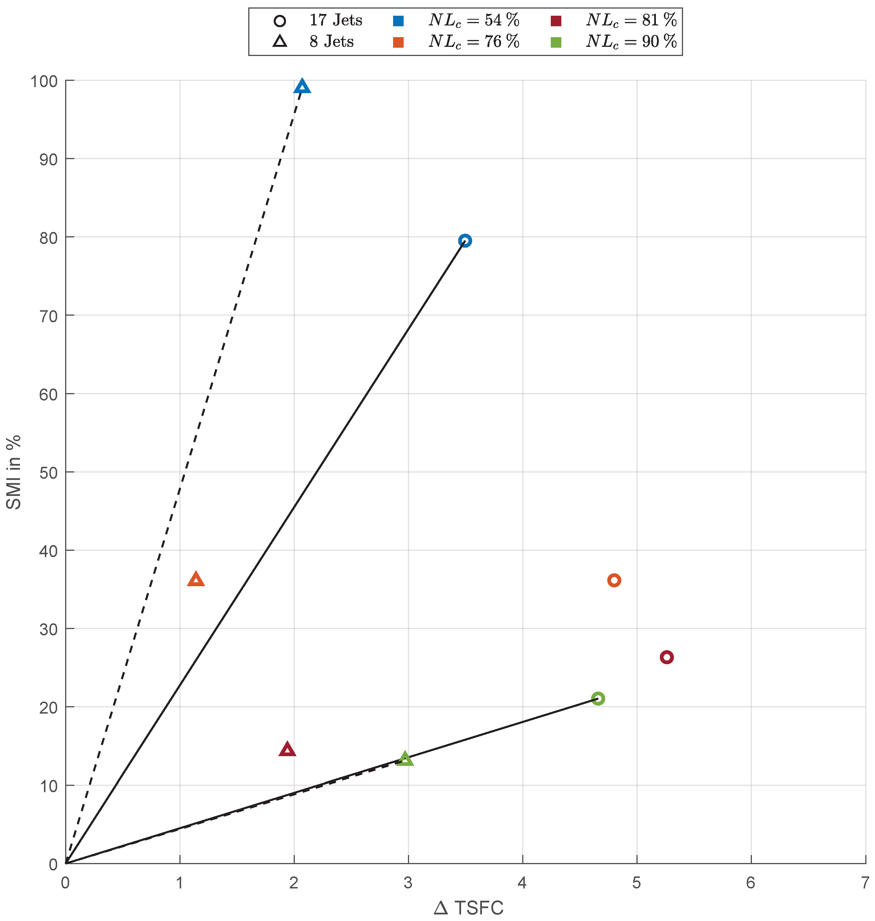
In the following section, the previously presented and analyzed SMI results are incorporated into the energy balance for a comprehensive cost-to-benefit analysis. As mentioned before, the most substantial SMI gains were observed at a spool speed of . For all configurations, a positive is notable, see Figure 12. The reason for the positive is primarily the reduction in thrust that occurs when bleed air is extracted. For example, at the operating point of , it was observed that a bleed air extraction of approximately 1.8% resulted in a 5.5% decrease in thrust. This behavior aligns with previous findings on engine bleed air extraction, for example, by Yuhas et al. [35].
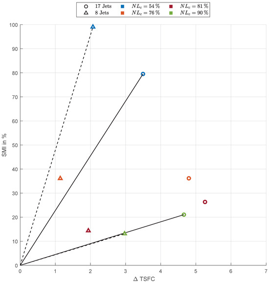
Figure 12.
Visualization of the TSFC and SMI at various experimentally investigated injection rates.
As in the previous chapter, the SMI is generally higher when using 17 injectors, except for the configuration at . Regarding , the configurations with only eight injectors consistently exhibit lower values compared to those with 17 injectors. In the cost-to-benefit analysis, a Pareto front () is included in the diagram for the operating points at and . The dashed line represents the configuration with eight jets, while the solid line corresponds to the configuration with 17 jets.
The diagram reveals that the eight-jet configuration demonstrates a steeper gradient, indicating a more favorable cost-to-benefit ratio at these spool speeds. However, as spool speed increases, the gradients for both configurations converge. This suggests that the relative advantage of the eight-jet configuration diminishes not only in terms of SMI but also with regard to the cost-to-benefit ratio. At , the gradients for both configurations become nearly identical.
Across all measurements, the for the eight-jet configuration is consistently lower than for the 17-jet configuration, reflecting a lower energy requirement. From this perspective, tip air injection with fewer jets appears to be more energy-efficient. The exception is at , where the cost-to-benefit analysis shows comparable performance between the two configurations.
5. Conclusions
In the previous sections, the function of the actuator, the AFC with the bleed air extraction and re-injection on the Larzac 04 engine, was shown. It was also demonstrated that the operating limits of the engine are extended with the AFC system up to 99%, which is substantially more than casing treatments. Furthermore, this system does not have a measurable negative impact on the flow when it is switched off [29].
Considering the extension of the operating range, the largest SMI was achieved at lower EOPs. However, the positive effect of the injection decreased with increasing speed. The first question of this paper addresses how the three parameters, velocity, mass flow and injection power, affect the stability margin improvement (SMI). It is demonstrated that the engine system and even the stall and surge conditions are very complex. It is not possible to indicate one parameter that is linked to a high SMI. But it seems that the power of the injection, with the high impact of the injection velocity, seems a good parameter, but also other factors and parameters have an impact.
With regard to the distribution of AFC ports (second question) fewer injection positions are better in terms of SMI and overall power balance. It is demonstrated that with an increase in the injected mass flow, the TSFC also rises. In this context, the performance of configurations with fewer jets is noteworthy. While the SMI was slightly lower (except at ), the , the injection penalty, was significantly reduced. Due to this reduction in TSFC, the current system is not suitable for continuous operation in a jet engine but may be ideal for short-term use. However, the thrust reduction during phases of bleed air extraction must be considered. Moreover, the evaluation of the power balance reveals potential for further optimization of the system, highlighting the overall benefits and future prospects of the AFC system.
Future work should focus on further optimizing the power balance and investigating advanced actuator designs to reduce flow loss and unsteady behavior. Additionally, integrating the AFC system with adaptive control strategies could enable a more dynamic response to varying operating conditions, enhancing its efficiency and applicability. By addressing these challenges, the AFC system could evolve into a viable solution for improving jet engine performance, not only during critical phases but also for broader applications in next-generation propulsion systems.
Author Contributions
Conceptualization, Y.S. and M.S.; methodology, Y.S., M.S. and A.B.; validation, Y.S., M.S. and D.K.; formal analysis, Y.S., M.S. and D.K.; investigation, Y.S. and M.S.; resources, Y.S., M.S. and D.K.; writing—original draft preparation, Y.S. and M.S.; writing—review and editing, Y.S. and M.S.; visualization, Y.S., M.S. and A.B.; supervision, M.S. and D.K.; project administration, M.S. and D.K.; funding acquisition, M.S. All authors have read and agreed to the published version of the manuscript.
Funding
This project (ACONIT) has received funding from the Clean Sky 2 Joint Undertaking under the European Union’s Horizon 2020 research and innovation programme under grant agreement No. 886352. We acknowledge financial support by FORscience Research Fund of the Universität der Bundeswehr München.
Institutional Review Board Statement
Not applicable.
Informed Consent Statement
Not applicable.
Data Availability Statement
Data available on request.
Acknowledgments
We are grateful to the technical staff at the IJP and all members of the ACONIT-project for the support during the project.
Conflicts of Interest
Author Arnaud Barnique was employed by the company CEDRAT TECHNOLOGIES SA. The remaining authors declare that the research was conducted in the absence of any commercial or financial relationships that could be construed as a potential conflict of interest.
Abbreviations
The following abbreviations are used in this manuscript:
| Compressor Ratio | |
| Humidity (relativ) | |
| ACONIT | Actuators for Surge Control in Gas Turbine |
| AFC | Active Flow Control |
| BAF | Bleed Air Feeding |
| BPR | Bypass ratio |
| CON | Connector |
| EOP | Engine Operating Point |
| F | Thrust |
| HPC | High Pressure Compressor |
| IGV | Inlet guide vane |
| IJP | Institute of Jet Propulsion |
| IOP | Injector Outlet Plane |
| LCP | Low Pressure Compressor |
| Low Pressure Spool-speed | |
| Corrected Low Pressure Spool-speed | |
| Corrected Mass Flow | |
| OPR | Overall Pressure Ratio |
| Power of the injected air per jet | |
| p | Static Pressure |
| Total (Stagnation) Pressure | |
| PJA | Pulsed Jet Actuator |
| SL | Stability Line |
| SM | Stability Margin |
| SMI | Stability Margin Improvement |
| Total Temperature | |
| TSFC | Thrust Specific Fuel Consumption |
References
- Day, I.J. Active Suppression of Rotating Stall and Surge in Axial Compressors. J. Turbomach. 1993, 115, 40–47. [Google Scholar] [CrossRef]
- Camp, T.R.; Day, I.J. A Study of Spike and Modal Stall Phenomena in a Low-Speed Axial Compressor. In ASME 1997 International Gas Turbine and Aeroengine Congress and Exhibition; ASME: New York, NY, USA, 1997. [Google Scholar] [CrossRef]
- Vo, H.D. Role of Tip Clearance Flow on Axial Compressor Stability. Ph.D. Thesis, Massachusetts Institute of Technology, Cambridge, MA, USA, 2002. [Google Scholar]
- Hathaway, M.D. Passive Endwall Treatments for Enhancing Stability; NASA/TM—2007-214409, ARL–TR–387; Glenn Research Center, NASA: Cleveland, OH, USA, 2007.
- Yoon, S.; Cargill, P. Casing Treatment: Its Potential and Limitations. J. Turbomach. 2023, 145, 041011. [Google Scholar] [CrossRef]
- Wilde, G.L. Improvements in or Relating to Gas Turbines. Patent No. GB 702576, 13 December 1950. [Google Scholar]
- Epstein, A.H.; Williams, J.E.F.; Greitzer, E.M. Active suppression of aerodynamic instabilities in turbomachines. J. Propuls. Power 1989, 5, 204–211. [Google Scholar] [CrossRef]
- Suder, K.L.; Hathaway, M.D.; Thorp, S.A.; Strazisar, A.J.; Bright, M.B. Compressor Stability Enhancement Using Discrete Tip Injection. J. Turbomach. 2001, 123, 14–23. [Google Scholar] [CrossRef]
- Freeman, C.; Wilson, A.G.; Day, I.J.; Swinbanks, M.A. Experiments in Active Control of Stall on an Aeroengine Gas Turbine. In Proceedings of the ASME 1997 International Gas Turbine and Aeroengine Congress and Exhibition, Orlando, FL, USA, 2–5 June 1997. [Google Scholar] [CrossRef]
- Moubogha, J.; Margalida, G.; Joseph, P.; Roussette, O.; Dazin, A. (Eds.) Surge Margin Improvement by Continuous and Pulsed Tip Injection; Paper ID: ETC2021-639; European Turbomachinery Society: Florence, Italy, 2021; Volume 2021. [Google Scholar]
- Wang, W.; Liu, B.; Lu, J.; Feng, J.; Chu, W.; Wu, Y. Comparative Study of Tip Injection in a Transonic and Subsonic Compressor. J. Turbomach. 2022, 144, 061009. [Google Scholar] [CrossRef]
- Beheshti, B.H.; Ghorbanian, K.; Farhanieh, B.; Teixeira, J.A.; Ivey, P.C. A New Design for Tip Injection in Transonic Axial Compressors. In Proceedings of the Proceedings of the ASME Turbo Expo 2006, New York, NY, USA, 6–11 May 2006; pp. 39–47. [Google Scholar] [CrossRef]
- Li, J.; Liu, Y.; Du, J.; Zhang, H.; Nie, C. Implementation of stability-enhancement with tip air injection in a multi-stage axial flow compressor. Aerosp. Sci. Technol. 2021, 113, 106646. [Google Scholar] [CrossRef]
- Kefalakis, M.; Papailiou, K.D. Active Flow Control for Increasing the Surge Margin of an Axial Flow Compressor. In Proceedings of the Volume 6: Turbomachinery, Parts A and B. ASMEDC, Barcelona, Spain, 8–11 May 2006; pp. 101–111. [Google Scholar] [CrossRef]
- Bindl, S. Realisierung Einer Autarken Applikation zur Erkennung und Unterdrückung von Verdichterinstabilitäten am Turbostrahltriebwerk Larzac 04. Ph.D. Thesis, University of the Bundeswehr Munich, München, Germany, 2010. [Google Scholar]
- Leinhos, D.C. Aktive Stabilisierung der Verdichterströmung in Einem Zweikreis-Turbostrahltriebwerk. Ph.D. Thesis, University of the Bundeswehr Munich, Neubiberg, Germany, 2003. [Google Scholar]
- Kern, F. Erkennung und Vermeidung von Verdichterinstabilitäten am Turbostrahltriebwerk Larzac 04. Ph.D. Thesis, University of the Bundeswehr Munich, Neubiberg, Germany, 2022. [Google Scholar]
- Scheidler, S.G. Untersuchung der Systemaspekte Stabilitätsverbessernder Maßnahmen in Gasturbinen. Ph.D. Thesis, University of the Bundeswehr Munich, Neubiberg, Germany, 2005. [Google Scholar]
- Stößel, M. Umsetzung und Erprobung eines Ejektor-Einblasesystems zur Stabilisierung des Niederdruckverdichters am Turbostrahltriebwerk Larzac 04. Ph.D. Thesis, University of the Bundeswehr Munich, Neubiberg, Germany, 2017. [Google Scholar]
- Stößel, M.; Bindl, S.; Niehuis, R. Ejector Tip Injection for Active Compressor Stabilization. In Proceedings of the ASME Turbo Expo 2014: Turbine Technical Conference and Exposition, Düsseldorf, Germany, 16–20 June 2014; Volume 2A: Turbomachinery; American Society of Mechanical Engineers: New York, NY, USA, 2014. [Google Scholar] [CrossRef]
- Kern, F.; Brehm, S.; Niehuis, R. Ejector tip injection system for active aerodynamic compressor stabilization part I: Design and experiment. In Proceedings of the 12th European Conference on Turbomachinery Fluid Dynamics and hermodynamics, European Turbomachinery Society, European Conference on Turbomachinery Fluid Dynamics and hermodynamics, Stockholm, Sweden, 3–7 April 2017. [Google Scholar] [CrossRef]
- Chuslo, L.A.; Greenburg, H.D. LARZAC: A Small Turbofan Engine for Military and General Aviation Aircraft; SAE Technical Paper Series; SAE International400 Commonwealth Drive: Warrendale, PA, USA, 1974. [Google Scholar] [CrossRef]
- Kern, F.; Bindl, S.; Kreitz, K.; Niehuis, R. Raising the Technology Level of an Instrumented Jet Engine Compressor Vane fabricated by Additive Manufacturing. In Proceedings of the XXIV International Symposium on Air Breathing Engines, ISABE-2019-24028, Canberra, Australia, 22–27 September 2019; pp. 1–15. [Google Scholar]
- Höhne, M. Untersuchung der aktiven Verdichterstabilisierung durch Verwendung eines Ab-, Ein- und Umblasesystems am Turbostrahltriebwerk LARZAC 04. Diplomarbeit Thesis, Institute of Jet Propulsion, University of the Bundeswehr Munich, Neubiberg, Germany, 2009. [Google Scholar]
- Strazisar, A.J.; Bright, M.M.; Thorp, S.; Culley, D.E.; Suder, K.L. Compressor Stall Control Through Endwall Recirculation. In Proceedings of the ASME Turbo Expo 2004, New York, NY, USA, 14–17 June 2004; pp. 655–667. [Google Scholar] [CrossRef]
- Schäfer, Y.; Stößel, M.; Kozulovic, D.; Niehuis, R. Entwurf Einer Aktiven Verdichterstabilisierung Durch Diskrete Lufteinblasung an Dem Turbofantriebwerk Larzac 04; Deutsche Gesellschaft für Luft- und Raumfahrt–Lilienthal-Oberth e.V.: Bonn, Germany, 2022. [Google Scholar] [CrossRef]
- Dazin, A.; Joseph, P.; Romano, F.; Gallas, Q.; Marty, J.; Aigouy, G.; Stößel, M.; Niehuis, R. The ACONIT project: An innovative design approach of active flow control for surge prevention in gas turbines. IOP Conf. Ser. Mater. Sci. Eng. 2021, 1024, 012068. [Google Scholar] [CrossRef]
- Schäfer, Y.; Stößel, M.; Kozulovic, D. D4.4 Final Test Report: ACONIT (Grant Agreement ID: 886352); European Commission: Brussels, Belgium, 2022. [Google Scholar] [CrossRef]
- Schäfer, Y.; Stößel, M.; Kozulovic, D. Study of Actuators and Injectors for Tip Air Injection in the Axial Compressor of the Larzac 04 Jet Engine. In Proceedings of the GPPS Chania24, Chania, Greece, 4–6 September 2024. [Google Scholar] [CrossRef]
- Schäfer, Y.; Stößel, M.; Kozulovic, D. D4.1 Critical Design Review (CDR): ACONIT (Grant Agreement ID: 886352); European Commission: Brussels, Belgium, 2022. [Google Scholar] [CrossRef]
- Schäfer, Y.; Stößel, M.; Kozulovic, D. D4.2 Test Readiness Review (TRR) Report: ACONIT (Grant Agreement ID: 886352); European Commission: Brussels, Belgium, 2023. [Google Scholar] [CrossRef]
- Schäfer, Y.; Stößel, M.; Kozulovic, D. D4.3 Documentation Test Databases: ACONIT (Grant Agreement ID: 886352); European Commission: Brussels, Belgium, 2023. [Google Scholar] [CrossRef]
- Weigl, H.J.; Paduano, J.D.; Fréchette, L.G.; Epstein, A.H.; Greitzer, E.M.; Bright, M.M.; Strazisar, A.J. 1997 Best Paper Award—Controls and Diagnostics Committee: Active Stabilization of Rotating Stall and Surge in a Transonic Single-Stage Axial Compressor. J. Turbomach. 1998, 120, 625–636. [Google Scholar] [CrossRef]
- Day, I.J. Stall, Surge, and 75 Years of Research. J. Turbomach. 2016, 138, 011001. [Google Scholar] [CrossRef]
- Yuhas, A.; Ray, R. Effects of bleed air extraction of thrust levels on the F404-GE-400 turbofan engine. In Proceedings of the 28th Joint Propulsion Conference and Exhibit, Nashville, TN, USA, 6–8 July 1992; p. 3092. [Google Scholar]


Disclaimer/Publisher’s Note: The statements, opinions and data contained in all publications are solely those of the individual author(s) and contributor(s) and not of MDPI and/or the editor(s). MDPI and/or the editor(s) disclaim responsibility for any injury to people or property resulting from any ideas, methods, instructions or products referred to in the content. |
© 2025 by the authors. Published by MDPI on behalf of the EUROTURBO. Licensee MDPI, Basel, Switzerland. This article is an open access article distributed under the terms and conditions of the Creative Commons Attribution (CC BY-NC-ND) license (https://creativecommons.org/licenses/by-nc-nd/4.0/).