1. Introduction
In the context of the European Horizon 2020 VOSTARS project [
1], we identified over 150 requirements by involving three teams of surgeons from different specialties, all of them had previous experiences with AR headsets and surgical navigators in the maxillo-facial, ENT (ear, nose, and throat), and neurosurgery areas. General opinions and advice were also collected from the industrial partners of the project consortium working in the surgical navigation field. The aim of this project was to develop a new-concept augmented reality (AR) head-mounted display (HMD) specifically tailored to support manual surgical procedures. The headset, intended to be connected to an external workstation, together with the associated software framework, was designed to support the in situ visualization of medical imaging data and is capable of deploying both video (VST) and optical (OST) see-through visualization modalities [
2].
The application or design requirements are related to optical aspects, electronics, form-factors, rendering modalities, and mechanical aspects. Taking into account the requests and feedback of the surgeons and the industrial partners, by common consensus we extracted a subset of ergonomics requirements, which are the
conditio sine qua non for the development of AR HMDs intended to be used as surgical guidance tools and, more broadly, as guiding tools for use in highly challenging manual procedures that must be carried out in the peripersonal space. Most of the literature on AR HMD technology deals with the requirements, and associated proposed solutions, of single hardware components with a non-holistic approach and without a clear focus on ergonomics, particularly when such devices are to be used to support highly challenging manual activities that must be carried out in the peripersonal space (i.e., for surgical guidance). State-of-the-art works have focused either on the AR display technology adopted [
2,
3,
4,
5,
6,
7] or optical elements [
8], electronic components, and rendering techniques [
9]. However, the same attention has not been devoted to mechanical requirements, particularly with regard to the ergonomics needed for the development of a non-general-purpose headset. As to the human-factor aspects, research works have mostly focused on the visualization issues that still hinder the mass adoption of similar devices [
10,
11]. We believe that the fact that most studies were and are still conducted by exploiting commercial AR headsets is
per se an intrinsic limitation. General-purpose OST-HMDs, such as the Microsoft© HoloLens
™ 1 and 2 and Magic Leap
™ 1 devices, are increasingly proposed as promising tools in the context of computer-aided surgery. Their use has been demonstrated on phantoms [
12,
13,
14,
15], in cadaver studies [
16,
17], and/or in pre and intra-operative planning tasks [
18,
19,
20,
21,
22]. More recently, one study demonstrated the use of Microsoft© HoloLens
™ 2 device in spine surgery on a real patient [
23]. The results of the study were rather promising, though, as stated by the authors, “
another potential limitation for broad clinical usage is the potential inconvenience associated with wearing a head-mounted device. Further studies evaluating experience and surgeon’s acceptance using this navigation are in progress”.
In their work in the context of image-guided neurosurgery, Nguyen et al. [
24] reported that seven out of nine participants of their user study felt some fatigue when wearing the HoloLens
™ 1 AR HMD after 10–15 min of use because of the way its weight is distributed. The authors stated that, since much of the weight is placed on the user’s forehead and nose, this may cause the user to progressively shift his/her gaze downwards over time. This gradual shift in posture could therefore cause neck strain and general discomfort.
Likewise, Lin et al. [
25] drew the same conclusion when describing the evaluation of a novel system for surgical telementoring based on Microsoft© HoloLens
™ 1 in the context of a user study where surgery residents performed lower-leg fasciotomies on cadaver patient models. More in detail, the authors reported that HoloLens
™ 1 “
inherits additional limitations of the AR HMD, such as a small field of view of the active part of the display, which confines annotation display to the center of the mentee’s field of view. Another limitation is the poor ergonomics of operating with a heavy and sometimes poorly fitting contraption attached to one’sh ead.”
Regarding surgery-specific HMDs, in [
26,
27], the first commercial FDA-approved AR headset for spine surgery was tested on real patients (Augmedics©, Chicago, IL, USA). The system features an OST HMD and relies on conventional marker-based target tracking: a registration marker was fixed on a clamp rigidly anchored to the spine. The approach is quite promising in terms of surgical outcome, but it also requires additional procedural steps (e.g., intra-operative CT for image-to-patient registration) and, once again, the ergonomics evaluated by the authors was sub-optimal: “
potential AR-mediated navigation adoption limitations include mechanical discomfort, visual discomfort and visual obstruction.” In the light of this, this work aims to describe these key requirements for the development of an ergonomic HMD for surgical guidance, the technical solutions we chose to meet such requirements, and the final results we obtained.
2. Research Gaps in Human Factors and Ergonomics Aspects of AR HMDs
Overall, in addition to the standard AR display-related performance, ergonomics and mechanical design play a crucial role in facilitating the acceptance of the AR HMD not only in the operating room but more broadly for all applications that require a high manual dexterity.
Yet, as stated by Garrett et al. [
28], “
virtually no research is currently available that addresses the safety and ergonomic impact of long-term usage; specifically, in the areas of cognition, upper body musculoskeletal disorders development, and impacts on the vestibular system. While mixed reality technologies have the potential to increase production and reduce quality failures, the safety and ergonomics risk hazards in industrial and occupational settings are unknown.”
Similarly, in their recent review of 82 articles focusing on the potentials and challenges associated with AR HMDs specifically devoted to aid logistics and supply chain management, Rejeb et al. [
29] pointed out that there are few studies that propose solutions to ergonomic challenges, especially when considering long-term usage. In addition, the authors explicitly recommend that AR HMD designers should work with ergonomics experts and ensure that devices are investigated across different working conditions.
This is also in accordance with the findings of Ito et al. [
30], who state that improving the comfort of HMDs requires specific considerations regarding weight balance.
As reported in the previous section, in their work concerning the potential benefits offered by AR in the operating room in the context of image-guided neurosurgery, Nguyen et al. [
24] highlighted that weight distribution is one of the main factors impacting the musculoskeletal system, which represents a limiting factor for the widespread adoption of mobile AR devices in the healthcare sector. Similar results were also obtained in [
25], a user study where several participants reported back and neck strain as they were forced to move the weight of their head and of the display away from their body.
To the best of the authors’ knowledge, no specific studies have been reported in the literature that provide insights into the design ergonomic requirements of AR HMDs specifically devoted to surgical navigation.
3. Materials and Methods
In this section, we describe the fundamental ergonomics requirements for the development of an AR HMD for surgical guidance. These requirements were identified by the members of the VOSTARS consortium with an activity that involved three groups of surgeons from different specialties: maxillo-facial, ENT (ear, nose, and throat), and neurosurgery. The collection of requirements started with interviews conducted by the team leader of each group of surgeons of their colleagues and involved a total of 10 surgeons (9 males and 1 female) with previous experience in using surgical navigators. The surgeons involved in the project helped designers by identifying their requirements after they had tested consumer-grade AR headsets, such as Microsoft© HoloLens™ 1, Magic Leap™ 1, and Lumus© Optical devices. This step ended with two plenary technical meetings involving all the partners of the project consortium, led by the industrial partner that develops and sells the surgical navigation systems. During these events, the surgeons’ and industrial partners’ requests were summarized. Some of these requirements were specific to the project and, above all, to the industrial product that VOSTARS aimed to develop with a high technology readiness level (TRL) (as dictated by the rules of the European project); therefore, we selected application requirements and optional requirements, as well as legal, regulatory, and normative requirements, each associated with the general conditions of use and environment. The application or design requirements are related to optical aspects, electronics, form-factors, rendering techniques, and mechanical aspects. Finally, taking into account the requests and feedback received from the surgeons and industrial partners, we agreed to extract a subset of seven ergonomics requirements we considered essential for AR HMDs to be used as surgical guidance tools and, more broadly, as guiding tools for highly challenging manual procedures in the peripersonal space.
Some of these requirements are intrinsically quantitative, while others are only qualitative in nature. However, we also tried to translate qualitative requirements into measurable quantitative values. Thereafter, in this study we report a list of the seven ergonomics requirements identified, not in order of relevance. Each requirement is explained starting from the surgeons’ feedback and is more stringent than those specified for general-purpose devices.
- (1)
The visor must provide unoccluded visibility of the working area (e.g., the surgical area).
The surgeon must be able to see and be in control of what happens around him/her and to freely interact with the surgical team. Specifically, the surgeon must see his/her own hands while he/she is handling surgical instruments. Therefore, while the surgeon is moving their gaze sideways and downwards, the peripheral vision of the surgical field should not be impaired; this also means that any rigid frame embedding the display’s optical combiners (OCs) should be avoided or made very thin.
- (2)
The surgeon must be allowed to wear his/her ophthalmic glasses.
The display eye relief (i.e., the eye-to-OC distance) should be at least 3 cm so that the surgeon is allowed to wear his/her ophthalmic glasses.
- (3)
The right and left OCs must be adaptable in order to match the majority of users in terms of interpupillary distance (IPD).
The HMD must be adaptable to all possible users, including those with the smallest and largest IPDs. The mean adult IPD is 63 mm, with the vast majority of adults having IPDs in the range 50–75 mm and with the wider range of 45–80 mm likely to include (almost) all adults [
31]. From a design standpoint, this requirement can be split into two: an opto-electronic requirement regarding the display and a mechanical one regarding the possibility of adjusting the relative distance between the display OCs. For clarity, but without any intention to be exhaustive because this aspect is beyond the scope of this article, for binocular viewing systems such as a wearable display device, the OCs have a small lateral margin to approximately center the user’s eyes on their optical axis. This small lateral margin of adjustment for varying IPDs is commonly referred to as the eye-box for each OC and is the range of allowed eye positions from where the whole image produced by the display is visible.
Therefore, a purely opto-electronic solution is not sufficient, and even rather impractical for consumer HMDs, to satisfy all possible users, as it would need an excessively wide eye-box. For this reason, the combination of both a mechanical and an opto-electronic solution is desirable. This requirement was transposed by us considering an IPD range between 56 and 70 mm.
- (4)
The visor must be tiltable.
The declination angle of the HMD is defined as the angle between the reference line that connects the top of the ears to the corner of the eyes and the optical axis of the display. The importance of the declination angle of the HMD is a key ergonomics factor. This requirement derives from the position of the surgeon when they are standing alongside the surgical table during most procedures. In this working position, surgeons usually prefer to direct their gaze downwards rather than tilting their neck to prevent work-related pain and injuries, especially when they have to maintain the position for a long time. The maximum head tilt recommended by ergonomic professionals is <
[
32]. A gaze rotation of about
downward is sufficient to view the patient without forcing neck rotation. Studies conducted by Takagi et al. [
3,
33] have demonstrated that the best position of the axis of rotation for display tilting is around the
x-axis of Fick [
34], as shown in
Figure 1, which is the horizontal axis that passes through the center of the eye and enables its pure vertical movement to preserve the quasi-orthoscopic setup of the HMD in VST mode as much as possible. For this reason, this requirement has been transposed as follows: rotation around the
x-axis of Fick up to 30
.
- (5)
When AR is not needed, the surgeon must be able to see naturally without completely removing the HMD.
Although there may be cases during a surgical procedure where the visor can be used intermittently, all the surgeons declared that removing and replacing their headset more than once is not advisable. From a design standpoint, this requirement has two consequences: on one hand, it means that the surgeon should be asked to wear the visor at the beginning of the procedure and remove it only when the surgical task is over; on the other hand, it means that a mechanism to make the visor as “transparent” as possible without removing it is needed.
- (6)
The visor should not be adjusted and/or moved by the surgeon during the procedure to maintain hand sterility.
This requirement has several implications, inter alia, ease of handling, but also that the assistant must not interfere with the surgeon during the procedure to handle the tilt or remove the visor.
- (7)
The total weight of the headset must be <350 g.
This requirement tells us what surgeons consider to be an ideal AR headset for surgery: something akin to their ophthalmic glasses, rather than a bulky helmet. Keeping in mind the weights and size of today’s commercially available AR headsets, this requirement gives us an idea of how far we are from the final goal.
The commercially available solutions mentioned in the previous paragraph meet none or only a few of the reported ergonomics requirements.
4. Solution
In this section, we will see how the ergonomics requirements identified were addressed by us in terms of dedicated mechanical solutions.
We decided to create a system that was as modular and simple as possible. The idea was that being a prototype, the HMD had to be able to be easily, quickly, and frequently assembled and disassembled by one, not necessarily qualified, operator using common tools.
The visor can be broken down into the following macro parts:
4.1. The U-Shaped Handle
Considering that the surgeon cannot touch and/or adjust the visor (requirement 6) and that the headset must be adjustable (requirement 4), we designed an ad hoc U-shaped handle that looks like a sort of ring or halo around the head of the surgeon. The underlying rationale is that an assistant can grip the handle from behind the surgeon’s shoulders without interfering with the surgeon during the procedure.
In our solution, this is a real handle system that operates with a mechanism that we will now describe in detail. From a kinematic point of view, the handle has two different rotation axes linked by two sliders placed on both sides of the surgeon’s face: one axis corresponds to the
x-axis of Fick’s coordinate system, which defines the axes moving with the eye [
35,
36], which hereinafter we will refer to as rotation around the eyes, passing through the eyes’ center of rotation as requested by requirement 4, whereas the second axis passes above the user’s ears and will be hereinafter be referred to as rotation around the ears, as shown in
Figure 1.
The exact position of this second rotation axis was determined after many iterations by optimizing forces and momenta when the final components were chosen. Rotation around the eyes is used to move the visor down as required by the surgeon; rotation around the ears is used to move the visor upward when the surgeon wants to view the field without removing the whole headset (requirement 5) and, above all, for safety reasons. Thus, we have two axes of rotation for two different events: the first aims to support the setting of the headset to a comfortable position. The second axis aims to control the “flip-up/parking” headset position. We carefully considered these two situations when we created the mechanism of the handle in detail: even if the movement seems to be identical, as they both operate the same handle, the downward rotation around the axis passing through the user’s eyes is controlled in a different way compared to the upward rotation around the user’s ears. More specifically, rotation around the ears is, properly speaking, a rototranslation. In the following subsections, we will give more details on how this mechanism works. Regarding the fulfilment of requirement 7, the handle is a counterweight. Without knowing a priori the weight of the opto-electronic components that are installed in the frontal part, we assumed that the majority of the total weight would be there. Knowing that we could not afford to have all the necessary components miniaturized ad hoc, it was decided that instead of striving for maximum weight reduction (which we have as far as possible regardless), we should aim to optimize the weight distribution. So, while, on one hand, we added weight by using the handle with respect to other more compact solutions, on the other hand, we shifted from a concentrated load, the one related to the opto-electronic part, to a more distributed load by moving the center of gravity of the visor towards the center of gravity of the head, from the forehead to the temples. Hence, we obtained, for the same weight, a better overall effect in terms of comfort. These aspects are discussed in detail in
Section 4.3.
4.1.1. Connection with the Head Mount
The mechanism that connects the head mount to the handle is itself part of the so-called handle system. The handle system is adaptable and it connects the handle, a rigid component with a fixed distance between its arms, with the head of the surgeon, the size of which varies, as shown in
Figure 2. We measured the head size of all the surgeons involved in the project and created a database for 10 surgeons (9 males and 1 female). The mechanism has to cover the gap between the temples and the handle. This gap varies from 0.5 up to 15 mm for each side. Another issue strictly connected to the previous one is that the surfaces connecting the inner part of the handle to the surgeon’s temples are not parallel, and the angle they also form changes from case to case.
Our solution was to create long and flexible sliders so that the handle system appeared as shown in
Figure 3.
Each slider has four holes, one for each angle of inclination, varying by steps of , from up to . These holes are placed on the same circumference with the center aligned with the axis around the eyes.
4.1.2. Rotation around the Eyes
In normal conditions, the system is engaged and stable. As shown in
Figure 4, by pushing a bar that is almost hidden inside the handle, the assistant activates a kinematic chain that unlocks the handle when the pins are pressed inside. In this way, the assistant can start rotating the visor around the eyes and release the bar. When the visor reaches more or less the desired angle, the assistant can simply continue the rotation until the pins snap inside the each holes of the slider (corresponding to the desired inclination) with a “click”.
To set up the visor in another configuration or to bring it back to the previous one, the procedure is identical.
4.1.3. Rotation around the Ears
When AR is not needed (requirement 5), the assistant adopts the same procedure described above by pushing the anti-panic handle to rotate the visor: when the visor is rotated back to reach the position, it stops rotating around the axis through the user’s eyes and starts moving around the axis passing through the user’s ears. When this rotation exceeds , the visor shifts naturally, pushed by its weight, to a block system that maintains the visor in an upright position. To resume working with the visor after it has been lifted, the procedure must be repeated in the reverse order.
4.2. The Frontal Part of the Visor
The frontal part of the visor contains the main electronic and optical components of the headset, which are:
To offer a modular solution that is easy to assemble and disassemble, we installed all the opto-electronic components on a rigid square frame, as shown in
Figure 5.
The displays were custom-made by Optinvent S.A., France [
37]. Among the other characteristics, the optical layouts of the waveguide-based OST displays:
are vertically oriented, and therefore leave the peripheral vision clear (requirement 1);
have no additional frame, which avoids the occlusion of the surgeon’s vision of the working area (requirement 1);
have a large field of view (FOV), a large eye-relief, a large eye-box, and a high optical engine transmissivity (requirement 2 & requirement 3);
have a refined shape to avoid contact with the surgeon’s cheeks or nose, especially when the visor is tilted downward by , which prevents problems such as sweat fogging the lenses or discomfort.
The pair of stereo RGB cameras are anchored to the displays to form a pair of camera/display modules (one for each side), and the IPD can be adjusted by loosening and tightening dedicated screws, as prescribed by requirement 3. As mentioned in [
33], the RGB cameras are placed as close as possible to the user’s eyes so as to preserve a quasi ortho-stereoscopic vision in VST mode. Moreover, the two displays are tilted downward and convergent to intercept a fixation point at around 40 cm from the user (i.e., the average working distance for a manual procedure). The shift from VST and OST mode is made possible by two customized, electrically controlled, optical shutters placed in front of the displays, manufactured by LC-Tec Displays AB, Sweden [
38]. These are transparent when the system works in OST mode and become opaque in VST mode. In order to meet the requirement 2 and improve comfort, and particularly to avoid excessive contact pressure or prevent sweat between the rear part of the visor and the surgeon’s forehead, we can adjust the frontal part with respect to the handle system by setting it with up/down and near/far movements. These mechanisms are inserted inside two lateral guides which connect the handle system with the frontal part. The near/far movement is guided by two precision screws, while the up/down movement is set manually by changing the position of two pins in a discrete way. The range is 4 mm up and 6 mm down with a step of 2 mm, as shown in
Figure 6.
The frontal part is not compact in terms of size, but still allows the surgeon to maintain his/her natural vision almost completely, this meeting requirement 1. Even the position and size of the eye tracking cameras have been defined to not obstruct the view.
4.3. The Head Mount
The head mount is a really unique device, as it provides:
a stable system on the head;
a balanced weight distribution;
connection with the handle system;
the secure maintenance of the visor in place.
Regarding the first two points, we conducted several tests in order to find the best points of contact with the head where the weight of the visor should be unloaded. We found out that weight is an important constraint in terms of ergonomics but not so critical under reasonable values, since it can be reduced in terms of the user’s perception once a good weight distribution is obtained. In other words, lighter HMDs may be perceived by the user as more cumbersome and intolerable than heavier ones. As shown in
Figure 7, this solution is based on two parts: a front unit and a rear unit. The rear unit can rotate with respect to the frontal one and is placed so as to be adjusted and tightened around the nape. We found that this is the best rear position, since it provides excellent stability thanks to a homogeneous weight distribution over the head, thus ensuring comfortable wearability. Comfort can be further improved by providing interchangeable sponges of different levels of hardness. The mechanisms used for locking/unlocking the straps (not shown in
Figure 7) are different for the frontal part and the rear part. The frontal part is fastened with a cinch, hook, and loop straps. This self-engaging design wraps firmly onto itself, provides a snug and secure fit when fastened, features easy engagement and fast release, and cinches tight for a secure hold. The rear part can be adjusted with a wheel ratchet size adjustment system. However, we observed that this solution is not good for the frontal part, as the weight tends to loosen and open the straps.
Regarding the last two points, on both sides the head mount has two protrusions with a hole in the middle, which fulfils these functions.
4.4. The Setup Procedure
Another crucial aspect is how we guarantee rotation around the axis through the centers of the eyes. The idea was that a perfect alignment was impossible to obtain for the simple reason that it is difficult to establish where the centers of the user’s eyes are exactly. The visor must be set up personally for each surgeon, a procedure that must be completed at least once before the first usage.
First, the surgeon must wear the head mount and adjust it until he or she feels it is stable, with the straps well tightened, especially those around the nape.
Then, the handle is mounted on the protrusions that are on both sides of the head mount and secured with two screws. During this operation, the head mount can be shifted until, ideally, the center of the circular part of the handle system on both sides is as close as possible to the centers of the surgeon’s eyes.
Finally, the frontal part should be adjusted. This macro part can be set by controlling the distance between the cover and the forehead and/or moving it up and down with respect to the line of sight until it is perfectly centered. During this step, the distance between the camera/display module is also adjusted, if needed, taking into account the IPD of the user.
5. Results
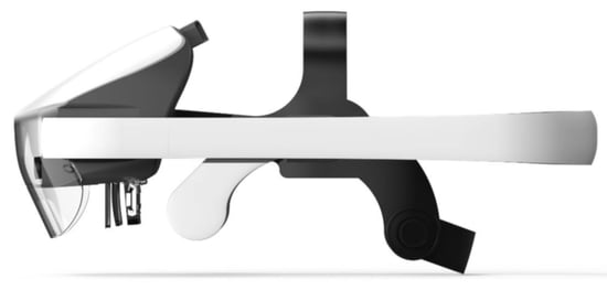
In
Figure 8 and
Figure 9, we show the mechanical solutions proposed and the visor in its standard configuration, tilted downward and upward.
Its main features are:
Length: 360 mm,
Height: 150 mm,
Width: 240 mm,
Weight: 840 g.
The weight indicated above does not include the weight of the cables that connect the visor to the workstation. Indeed, the visor is just a component of the entire system and also includes a workstation (a dedicated laptop running the software framework that controls the AR platform), a safety board, and an emergency pedal [
39]. The laptop must be placed far from the surgical table so that it does not interfere with the surgical staff.
Moreover, for the same reason, cables must be lifted from the ground to prevent anyone from tripping over them.
In
Table 1, we compare our prototype with the most commonly used consumer-grade AR HMDs in terms of the design solutions proposed to address the ergonomics requirements.
The prototype was preliminarily tested by three final users who specialized in maxillo-facial surgery, paediatric neurosurgery, and neurosurgery. All these final users were surgeons and members of the consortium, with substantial experience with other AR devices and particularly with our proof-of-concept version of the VOSTARS headset [
39,
40]. All the surgeons performed AR exercises by wearing the visors for at least 15 min consecutively. After the exercises, the surgeons were administered a brief five-entry monotone Likert questionnaire regarding their overall impression of the design. The results are shown in
Table 2, with scores ranging from 1 (totally disagree) to 5 (totally agree).
6. Discussion
The overarching objective of this article is the presentation of a list of key ergonomics design requirements that will be the pillars for the creation of a truly ergonomic AR visor to support manual activities. This work was carried out in full awareness that, so far, not much attention has been dedicated to exhaustively listing such design specifics in the literature. The authors hope that this article may provide a good guide for future engineers or, in the best of predictions, be a milestone for the good design of future devices. These requirements were selected from a longer list of requirements that led us to the development of a new-concept AR HMD devoted to surgical guidance (i.e., the VOSTARS system). In this work, we identified these design requirements, explained how these requirements have been addressed through innovative mechanical solutions, and discussed how these solutions have been or could be used for the implementation of an AR headset to support highly challenging manual procedures such as surgery. The result of our work is the list of requirements identified, which may be validated in the future as we optimize our prototype or by someone else who may follow these requirements to test their own devices in an operating theater.
Henceforth, we will use
Figure 8 and
Figure 9 as references for our discussion and
Table 3 to discuss the proposed solutions.
Although our solution is not compact in terms of its size, it fulfils requirement 1 in terms of vision: the view is only obstructed when looking upwards, but remains unobstructed in all the other directions. This was made possible mainly thanks to the ad hoc vertical OCs produced by Optinvent S.A., which do not include any frame around them and offer a high optical engine transmissivity. The large eye relief and eye-box, together with the possibility to set the frontal part in all directions (upward, downward, forward, and backward), allow the surgeon to comfortably wear his/her ophthalmic glasses, even bulky ones, in compliance with requirement 2. By manually setting the position of the OCs according to his/her own IPD, the surgeon can obtain an orthoscopic view, as requested by requirement 3. The visor allows for a downward tilt of up to 30
, as dictated by requirement 4. This inclination was made possible by enabling the rotation of the visor around the user’s eyes axis. Moreover, the visor can be rotated upward when needed, and, in this case, the rotation is around the user’s ears axis, as specified by requirement 5. The U-shaped handle allows an assistant to rotate the visor without interfering with the surgical procedure and thereby maintain the sterility of the surgeon, as specified in requirement 6. The total weight of the whole visor is undoubtedly higher than the weight specified by requirement 7 (i.e., ≤350 g). Yet, we tried to mitigate this issue by balancing the weight around the user’s head. Moreover, there are wide margins of improvement with a more manufacturing-oriented approach that includes the miniaturization of integrated circuits and most opto-electronic components. However, the fact that the surgeons wore the visor on their heads for 15 min can be considered a great success because it means that a correct distribution of weight can make all the difference (point 1 & 2 in
Table 2). It must be noted that we carried out another test involving the same maxillo-facial surgeon who performed the tests on the table. When we removed only the protective glass from the front (60 g), the comfort increased considerably and the time of use of the visor increased accordingly. The surgeon felt comfortable wearing the visor for over half an hour while he was applying a suture on a medical mannequin.
The miniaturization of all components is essential to not only reduce the total weight of the device, but also to reduce its overall size. The next steps required to improve the general wearability of the device will be to enlarge the straps on the nape and to move the position of the straps of the frontal part to the parietal side of the head (points 3 & 4 in
Table 2). The movement of the handle is fluid, but less than expected. This depends on the considerations we developed in
Section 4.1.1 regarding the gap and lack of parallelism between the handle and the user’s temple and how these values can vary significantly from case to case (point 5). A further improvement to reduce the weight could be obtained by simply modifying the shape of the bar, which is currently too large, even if it is considered to be an anti-panic solution. The mechanical design itself can be improved through a more manufacturing-oriented approach. The total number of components could be reduced and, each movement, now controlled in discrete steps, could be replaced by a continuous movement mechanism, a feature that could significantly affect the evaluation of point 5. Finally, the weight and the overall size of the device could be reduced as well by taking into account different manufacturing solutions with respect to the current prototype.
It is worth mentioning that a first proof-of-concept version of the headset, with the same main components and the same software framework for surgical navigation [
39,
41], has already been used to guide complex 3D trajectory tracing tasks on 3D-printed replicas of bony anatomies [
40,
42] and on real patients to aid surgeons in performing Le Fort 1 osteotomies in craniomaxillofacial surgery [
43].
7. Conclusions
In the context of a European project, we identified over 150 design requirements for the development of an AR HMD specifically tailored to support highly challenging manual surgical procedures. The requirements were established by surgeons from different specialties and by industrial players working in the surgical field who both had a strong commitment to the exploitation of this technology. Some of these requirements are specific to the project, while others can be seen as “must-have” or key features for an efficient and reliable AR headset devoted to supporting manual activities in the peripersonal space. In full awareness of the fact that, so far in the literature, not much attention has been dedicated to exhaustively listing such design specifics, this article aims to be a good guide for future engineers or, at best, a milestone for the good design of future devices. In this work, we disclosed ergonomic design requirements from the surgeon’s viewpoint and explained how these requirements have been addressed through possible mechanical solutions and how these innovative solutions can be used for the implementation of an AR headset for surgery. Preliminary evaluation tests have shown that, even if the overall results are not conclusive, they are rather encouraging, and the weight reduction remains the only real open issue. Many improvements can still be made, such as miniaturizing the opto-electronic components of the device and the mechanical design itself through a more manufacturing-oriented approach. However, a more structured user study is needed to provide conclusive evidence regarding the effectiveness and reliability of the proposed mechanical solutions in addressing the key ergonomic requirements analyzed in this paper. We believe that the ideas and solutions proposed in this paper may pave the way for the creation of an authentically ergonomic AR headset to support high-precision manual procedures such as surgery.
Author Contributions
Conceptualization, G.B. and V.F.; methodology, R.D., H.H. and H.L.; software, R.D. and H.L.; validation, G.B. and M.C.; resources, M.C.; writing—original draft preparation, R.D. and F.C; writing—review and editing, R.D. and F.C.; visualization, R.D.; supervision, V.F.; project administration, M.C. All authors have read and agreed to the published version of the manuscript.
Funding
This research was funded by the Horizon 2020 H2020-ICT-2016-2017, grant number 731974, and by the Italian Ministry of Education and Research (MIUR) in the framework of the CrossLab project (Departments of Excellence), Laboratory of Augmented Reality, University of Pisa, Pisa, Italy.
Institutional Review Board Statement
The study was conducted according to the guidelines of the Declaration of Helsinki, and approved by the Ethics Committee of Area Vasta Emilia Centro University of Bologna (protocol code 3749/2019, date of approval 22 October 2019) and the Italian Ministry of Health (protocol code 70942, date of approval 17 December 2019).
Informed Consent Statement
Informed consent was obtained from all subjects involved in the study. Written informed consent was obtained from the patient(s) to publish this paper.
Data Availability Statement
Not applicable.
Acknowledgments
The authors wish to thank all the members of the consortium. Special thanks go to Khaled Sarayeddine, Simon Julien, Daniel László-Deli, Donghyun Kim, Sungchul Yang, and Pierre Sorgniard.
Conflicts of Interest
The authors declare no conflict of interest.
Abbreviations
The following abbreviations are used in this manuscript:
| AR | Augmented Reality |
| CT | Computed Tomography |
| FOS | Fast Optical Shutter |
| FOV | Field Of View |
| HMD | Head-Mounted Display |
| IMU | Inertial Measurement Unit |
| IPD | InterPupillary Distance |
| LC | Liquid Crystal |
| OC | Optical Combiner |
| OST | Optical See Through |
| RGB | Red Green Blue |
| TRL | Technology Readiness Level |
| VOSTARS | Video Optical See-Through Augmented Reality (Surgical) System |
| VST | Video See Through |
References
- VOSTARS H2020 Project, G.A. 731974. Available online: http://www.vostars.eu/ (accessed on 1 November 2021).
- Rolland, J.P.; Fuchs, H. Optical Versus Video See-Through Head-Mounted Displays in Medical Visualization. Presence 2000, 9, 287–309. [Google Scholar] [CrossRef]
- Takagi, A.; Yamazaki, S.; Saito, Y.; Taniguchi, N. Development of a stereo video see-through HMD for AR systems. In Proceedings of the IEEE and ACM International Symposium on Augmented Reality (ISAR 2000), Munich, Germany, 5–6 October 2000; pp. 68–77. [Google Scholar] [CrossRef]
- Hua, H.; Javidi, B. A 3D integral imaging optical see-through head-mounted display. Opt. Express 2014, 22, 13484–13491. [Google Scholar] [CrossRef] [PubMed]
- Park, J.H.; Kim, S.B. Optical see-through holographic near-eye-display with eyebox steering and depth of field control. Opt. Express 2018, 26, 27076–27088. [Google Scholar] [CrossRef] [PubMed]
- Itoh, Y.; Langlotz, T.; Sutton, J.; Plopski, A. Towards Indistinguishable Augmented Reality: A Survey on Optical See-through Head-Mounted Displays. ACM Comput. Surv. 2021, 54, 1–36. [Google Scholar] [CrossRef]
- Xiong, J.; Hsiang, E.L.; He, Z.; Zhan, T.; Wu, S.T. Augmented reality and virtual reality displays: Emerging technologies and future perspectives. Light. Sci. Appl. 2021, 10, 216. [Google Scholar] [CrossRef]
- Kress, B.C. Optical Architectures for Augmented-, Virtual-, and Mixed-Reality Headsets; SPIE: Bellingham, WA, USA, 2020. [Google Scholar]
- Naira, E.; Shaker, E.S.; Ahmed, A.; Hassan, S.; Mohammed, E.; Louai, A.; Nagham, M. Overlapping Shadow Rendering for Outdoor Augmented Reality. Comput. Mater. Contin. 2021, 67, 1915–1932. [Google Scholar] [CrossRef]
- Robert, P.; Marc D., W.; Byron J., P. Perceptual Issues in the Use of Head-Mounted Visual Displays. Hum. Factors 2006, 48, 555–573. [Google Scholar] [CrossRef]
- El Jamiy, F.; Marsh, R. Survey on Depth Perception in Head Mounted Displays: Distance Estimation in Virtual Reality, Augmented Reality, and Mixed Reality. IET Image Process. 2019, 13, 707–712. [Google Scholar] [CrossRef]
- Wang, L.; Sun, Z.; Zhang, X.; Sun, Z.; Wang, J. A HoloLens Based Augmented Reality Navigation System for Minimally Invasive Total Knee Arthroplasty. In Intelligent Robotics and Applications; Yu, H., Liu, J., Liu, L., Ju, Z., Liu, Y., Zhou, D., Eds.; Springer International Publishing: Cham, Switzerland, 2019; pp. 519–530. [Google Scholar]
- Gibby, J.T.; Swenson, S.A.; Cvetko, S.; Rao, R.; Javan, R. Head-mounted display augmented reality to guide pedicle screw placement utilizing computed tomography. Int. J. Comput. Assist. Radiol. Surg. 2019, 14, 525–535. [Google Scholar] [CrossRef] [PubMed]
- Rose, A.S.; Kim, H.; Fuchs, H.; Frahm, J.M. Development of augmented-reality applications in otolaryngology–head and neck surgery. Laryngoscope 2019, 129, S1–S11. [Google Scholar] [CrossRef]
- Gao, Y.; Lin, L.; Chai, G.; Xie, L. A feasibility study of a new method to enhance the augmented reality navigation effect in mandibular angle split osteotomy. J. Cranio-Maxillofac. Surg. 2019, 47, 1242–1248. [Google Scholar] [CrossRef] [PubMed]
- Müller, F.; Roner, S.; Liebmann, F.; Spirig, J.M.; Fürnstahl, P.; Farshad, M. Augmented reality navigation for spinal pedicle screw instrumentation using intraoperative 3D imaging. Spine J. 2020, 20, 621–628. [Google Scholar] [CrossRef] [PubMed]
- Burström, G.; Persson, O.; Edström, E.; Elmi-Terander, A. Augmented reality navigation in spine surgery: A systematic review. Acta Neurochir. 2021, 163, 843–852. [Google Scholar] [CrossRef]
- Jang, J.; Tschabrunn, C.M.; Barkagan, M.; Anter, E.; Menze, B.; Nezafat, R. Three-dimensional holographic visualization of high-resolution myocardial scar on HoloLens. PLoS ONE 2018, 13, e0205188. [Google Scholar] [CrossRef] [PubMed]
- Tepper, O.M.; Rudy, H.L.; Lefkowitz, A.; Weimer, K.A.; Marks, S.M.; Stern, C.S.; Garfein, E.S. Mixed Reality with HoloLens: Where Virtual Reality Meets Augmented Reality in the Operating Room. Plast. Reconstr. Surg. 2017, 140, 1066–1070. [Google Scholar] [CrossRef]
- Li, Y.; Chen, X.; Wang, N.; Zhang, W.; Li, D.; Zhang, L.; Qu, X.; Cheng, W.; Xu, Y.; Chen, W.; et al. A wearable mixed-reality holographic computer for guiding external ventricular drain insertion at the bedside. J. Neurosurg. JNS 2019, 131, 1599–1606. [Google Scholar] [CrossRef]
- Incekara, F.; Smits, M.; Dirven, C.; Vincent, A. Clinical Feasibility of a Wearable Mixed-Reality Device in Neurosurgery. World Neurosurg. 2018, 118, e422–e427. [Google Scholar] [CrossRef]
- Scherl, C.; Stratemeier, J.; Rotter, N.; Hesser, J.; Schönberg, S.O.; Servais, J.J.; Männle, D.; Lammert, A. Augmented Reality with HoloLens® in Parotid Tumor Surgery: A Prospective Feasibility Study. ORL 2021, 83, 439–448. [Google Scholar] [CrossRef]
- Farshad, M.; Fürnstahl, P.; Spirig, J.M. First in man in-situ augmented reality pedicle screw navigation. N. Am. Spine Soc. J. (NASSJ) 2021, 6, 100065. [Google Scholar] [CrossRef]
- Nguyen, N.Q.; Cardinell, J.; Ramjist, J.M.; Androutsos, D.; Yang, V.X.D. Augmented reality and human factors regarding the neurosurgical operating room workflow. In Optical Architectures for Displays and Sensing in Augmented, Virtual, and Mixed Reality (AR, VR, MR); Kress, B.C., Peroz, C., Eds.; International Society for Optics and Photonics, SPIE: San Francisco, CA, USA, 2020; Volume 11310, pp. 119–125. [Google Scholar] [CrossRef]
- Lin, C.; Andersen, D.; Popescu, V.; Rojas-Muñoz, E.; Cabrera, M.E.; Mullis, B.; Zarzaur, B.; Anderson, K.; Marley, S.; Wachs, J. A First-Person Mentee Second-Person Mentor AR Interface for Surgical Telementoring. In Proceedings of the 2018 IEEE International Symposium on Mixed and Augmented Reality Adjunct (ISMAR-Adjunct), Munich, Germany, 16–20 October 2018; pp. 3–8. [Google Scholar] [CrossRef]
- Molina, C.A.; Sciubba, D.M.; Greenberg, J.K.; Khan, M.; Witham, T. Clinical Accuracy, Technical Precision, and Workflow of the First in Human Use of an Augmented-Reality Head-Mounted Display Stereotactic Navigation System for Spine Surgery. Oper. Neurosurg. 2020, 20, 300–309. [Google Scholar] [CrossRef]
- Yahanda, A.T.; Moore, E.; Ray, W.Z.; Pennicooke, B.; Jennings, J.W.; Molina, C.A. First in-human report of the clinical accuracy of thoracolumbar percutaneous pedicle screw placement using augmented reality guidance. Neurosurg. Focus 2021, 51, E10. [Google Scholar] [CrossRef] [PubMed]
- Garrett, G.A.; Reid, C.R.; Jenkins, M.; Talbot, T.; Doherty, S. Effects of Prolonged Use of Mixed Reality Systems in Occupational Settings Discussion Panel. Proc. Hum. Factors Ergon. Soc. Annu. Meet. 2018, 62, 2104–2106. [Google Scholar] [CrossRef]
- Rejeb, A.; Keogh, J.G.; Leong, G.K.; Treiblmaier, H. Potentials and challenges of augmented reality smart glasses in logistics and supply chain management: A systematic literature review. Int. J. Prod. Res. 2021, 59, 3747–3776. [Google Scholar] [CrossRef]
- Ito, K.; Tada, M.; Ujike, H.; Hyodo, K. Effects of the Weight and Balance of Head-Mounted Displays on Physical Load. Appl. Sci. 2021, 11, 6802. [Google Scholar] [CrossRef]
- Dodgson, N.A. Variation and extrema of human interpupillary distance. In Stereoscopic Displays and Virtual Reality Systems XI; Bolas, M.T., Woods, A.J., Merritt, J.O., Benton, S.A., Eds.; International Society for Optics and Photonics, SPIE: San Jose, CA, USA, 2004; Volume 5291, pp. 36–46. [Google Scholar] [CrossRef]
- Voruganti, K. Practice dentistry pain-free: Evidence-based strategies to prevent pain and extend your career. Br. Dent. J. 2009, 206, 181. [Google Scholar] [CrossRef][Green Version]
- Cattari, N.; Cutolo, F.; D’Amato, R.; Fontana, U.; Ferrari, V. Toed-in vs Parallel Displays in Video See-Through Head-Mounted Displays for Close-Up View. IEEE Access 2019, 7, 159698–159711. [Google Scholar] [CrossRef]
- Wright, K.W. Anatomy and Physiology of Eye Movements. In Pediatric Ophthalmology and Strabismus; Springer: New York, NY, USA, 2003; pp. 125–143. [Google Scholar] [CrossRef]
- Robinson, D.A. A Method of Measuring Eye Movemnent Using a Scieral Search Coil in a Magnetic Field. IEEE Trans. Bio-Med. Electron. 1963, 10, 137–145. [Google Scholar] [CrossRef]
- Iskander, J.; Hossny, M.; Nahavandi, S. A Review on Ocular Biomechanic Models for Assessing Visual Fatigue in Virtual Reality. IEEE Access 2018, 6, 19345–19361. [Google Scholar] [CrossRef]
- Optinvent. Available online: https://www.optinvent.com/ (accessed on 1 November 2021).
- Lc-Tec. Available online: https://www.lc-tec.se/ (accessed on 1 November 2021).
- Cercenelli, L.; Carbone, M.; Condino, S.; Cutolo, F.; Marcelli, E.; Tarsitano, A.; Marchetti, C.; Ferrari, V.; Badiali, G. The Wearable VOSTARS System for Augmented Reality-Guided Surgery: Preclinical Phantom Evaluation for High-Precision Maxillofacial Tasks. J. Clin. Med. 2020, 9, 3562. [Google Scholar] [CrossRef] [PubMed]
- Condino, S.; Fida, B.; Carbone, M.; Cercenelli, L.; Badiali, G.; Ferrari, V.; Cutolo, F. Wearable Augmented Reality Platform for Aiding Complex 3D Trajectory Tracing. Sensors 2020, 20, 1612. [Google Scholar] [CrossRef] [PubMed]
- Cutolo, F.; Fida, B.; Cattari, N.; Ferrari, V. Software Framework for Customized Augmented Reality Headsets in Medicine. IEEE Access 2020, 8, 706–720. [Google Scholar] [CrossRef]
- Condino, S.; Montemurro, N.; Cattari, N.; D’Amato, R.; Thomale, U.; Ferrari, V.; Cutolo, F. Evaluation of a Wearable AR Platform for Guiding Complex Craniotomies in Neurosurgery. Ann. Biomed. Eng. 2021, 49, 2590–2605. [Google Scholar] [CrossRef] [PubMed]
- VOSTARS Project: Video in the Operating Room. Available online: https://www.youtube.com/watch?v=N8qZUj4amm0&feature=emb_title/ (accessed on 18 October 2021).
| Publisher’s Note: MDPI stays neutral with regard to jurisdictional claims in published maps and institutional affiliations. |
© 2022 by the authors. Licensee MDPI, Basel, Switzerland. This article is an open access article distributed under the terms and conditions of the Creative Commons Attribution (CC BY) license (https://creativecommons.org/licenses/by/4.0/).


 ,
, 


