1. Introduction
The international circumpolar active layer (CALM) and permafrost temperature (GTN-P) monitoring systems in the natural landscapes of the Arctic and Subarctic have shown their effectiveness and viability. The observations of these systems are in demand by analysts and researchers studying the impact of climate warming on permafrost. At the same time, the changes in the permafrost of settlements have been practically ignored by scientists. The ongoing studies on this topic, as well as long-term observations of permafrost parameters in cities, are not systematic. They are often carried out by initiative groups of scientists without proper funding or a long-term perspective. It is believed that monitoring the state of permafrost in urban cities and towns is not directly related to fundamental science and is an applied form of research.
The purpose of this research was to substantiate new approaches to the organization of permafrost monitoring in urbanized areas. To achieve this, it was proposed to analyze the results of our work on the organization of a network of observations of dangerous exogenous cryogenic processes in Anadyr. An important part of this research was an analysis of recent publications devoted to the study of permafrost formation processes in anthropogenic landscapes, applied research methods, and the peculiarities of the impact of climate change on the urban environment in the cryolithozone. The introductory part of this work also presents a critical analysis of the existing approach to the organization and management of the geotechnical monitoring of permafrost in populated areas. A description of the research object is provided from the point of view of the suitability of Anadyr for the introduction and testing of new approaches to monitoring permafrost and assessing the impact of climate change on the urban environment. When describing dangerous ground-warming zones identified by GPR profiling, remarks are made about their genesis, seasonal dynamics, and evolution. This article concludes with the authors’ proposals on the organization of monitoring and a network for the placement of observation wells and geophysical profiles in Anadyr.
2. Statement of Problem
About 5 million people live in 1162 settlements in the circumpolar permafrost region. Of these, 3.3 million live in areas where there is active degradation of permafrost caused by climate warming [
1,
2,
3]. The main threats to the population are breakage and permanent disruptions to the functioning of residential, energy, and transport infrastructure. According to independent estimates in the Arctic and Subarctic, the loss of the bearing capacity of building foundations, depending on the time of their construction and the rate of climate warming, is 12–40% [
4,
5]. Model calculations show that, with the warming of permafrost from −4 to −1 °C in the 21st century, the loss of the bearing capacity of pile foundations will reach 75% [
3].
The restoration of infrastructure in the cryolithozone will require significant financial expenditures from the governments of circumpolar states [
4,
6]. At the same time, the existing permafrost–climate forecast models take little account of the specifics of the geocryological conditions of urbanized territories [
4]. Therefore, it is difficult to predict the real amounts of materials and the financial costs necessary for the complete reconstruction of the infrastructure. Thus, the best option at this stage of uncertainty is to adapt the existing infrastructure of populated areas to the current climate changes [
7]. To achieve this, it is necessary to establish the systematic monitoring of the permafrost conditions of cities and towns, with a focus on stopping the threats of expanding ground-thawing zones, which include the destruction of buildings, utilities, and road surfaces [
8].
Researchers studying the influence of climate warming on the permafrost roof in natural landscapes, along with an increase in the thickness of the active layer, are paying attention to the threat of the subsidence of the Earth’s surface, which is associated with the melting of shallow underground ice [
9,
10]. The subsidence of the surface is a consequence of thermokarst, which is described in classical scientific works on geocryology and is extremely uneven in space [
11,
12]. In natural landscapes, the result of thermokarst on flat terrain is the formation of swamps and shallow lakes, and on mountain slopes, it results in linear melting zones, which represent groundwater runoff routes. In addition to low-mountain landscapes, linear thermokarst is typical for marine and river terraces [
13,
14,
15,
16,
17,
18]. On the surface, taliks usually correspond to depressions and shallow ravines with drying streams [
16,
19]. The thickness of subaerial and subaqual talik zones is usually 5–12 m, but they can reach 18–20 m [
4,
14,
15]. Infiltrating atmospheric precipitation, melt water from underground ice, and condensation waters are the sources of nutrition for the suprapermafrost waters of taliks [
20]. The formation and runoff of condensation waters in the active layer of the mountain–tundra landscapes of the cryolithozone comprise one of the main sources of nutrition for rivers and groundwater [
21]. Under the conditions of the rugged relief of the slopes and the mosaic structure of the cryolithological basis of the landscape, talik zones form a complex structure [
4,
17,
18,
22,
23,
24,
25,
26]. By changing the configuration of the boundaries, hydrogenic talik zones thaw out arrays of frozen soils, not from the surface, as with the radiation–convective effect of the atmosphere, but along the front of their expansion and deepening. Most of the populated areas in the Arctic and Subarctic are located on sea and river terraces, as well as on the slopes of low mountains.
It is difficult to predict the development of talik zones in natural and anthropogenic landscapes using climate modeling. This is due to the fact that the dynamics of hydrogenic taliks are indirectly related to current climate changes through intermediate links of climatic and cryohydrogeological processes [
1,
14,
16,
18]. Therefore, in order to predict the impact of talik zone dynamics on the stability of the foundations of buildings and structures, comprehensive monitoring of the physical and spatial characteristics of thawed and thawing grounds is necessary, followed by the statistical modeling of dangerous exogenous cryogenic processes.
An H.M. French talik refers to the unfrozen ground located between the layer of seasonal freezing and the upper surface of permafrost rocks [
27]. In another definition, only thawed areas of permafrost surrounded by frozen grounds are classified as talik zones. Other definitions of taliks are also known, in which the authors focus on certain aspects of talik formation or the physical parameters of thawed soil [
28]. Therefore, it is necessary to clarify which taliks pose a threat to the infrastructure of populated areas and require monitoring:
Talik zones bounded by permafrost from below, consisting of thawed or cooled plastically frozen soils with temperatures above the freezing point of soil and loosely bound water (>Tbf). For soils of a sandy–clay composition, the freezing point, Tbf, is usually in the range from −0.3 to −1.5 °C [
29].
Buried unfrozen taliks or those thawed to temperatures equal to the Tbf or above, with formerly frozen soil (which contains an excess of hygroscopic moisture) and loosely bound and free water.
Subaerial talik zones, bounded at their maximum depth and along their flanks by permafrost and overlain by a layer of seasonal freezing. In plans and sections, such taliks have the shape of a buried mulda.
Hydrogenic talik zones containing groundwater aquifers with a feeding and unloading area, and hydrostatic and cryogenic pressure.
As can be seen, the main property of talik zones, which pose a danger to the infrastructure of settlements, is their ability to transfer accumulated or incoming heat from the atmosphere to the surrounding permafrost soil in a convective–conductive way. Unfrozen soils, deep-lying cryopags, and the taliks of temporary artificial earth embankments do not pose a danger to the frozen soils of the base.
Significant advances have been achieved in the study of the morphology and electrophysical properties of talik zone soils using a complex of near-surface geophysical methods [
14,
15,
17,
23,
26,
30,
31]. It is important to note that, even 20–15 years ago, near-surface geophysics was used exclusively as an auxiliary method in conducting engineering surveys for construction and in the geological exploration of mineral deposits [
32,
33,
34,
35,
36]. In the last decade, geophysical methods have been increasingly used as independent methods, for which the drilling of reference and test wells is an auxiliary method. The peculiarity of such studies in the cryolithozone is that they allow for the detection of the signs of cryogenic processes (thawing and freezing, watering, thermokarst, frost heaving, solifluction, and cryogenic salinization). In addition, it is possible to conduct repeated seasonal and interannual geophysical research in order to study the spatial and temporal dynamics of cryogenesis [
26]. In the detailed study of the near-surface sections of the permafrost roof, tomographic geophysical methods have priority [
23,
26]. Subsurface georadolocation sounding methods are used for in-line inspections of vast territories with the separation of thawed and frozen soils, underground ice, and aquifers in the context of the boundaries [
34,
37,
38]. In an urban environment, the use of individual electrical and seismoacoustic methods is limited by interference from the reinforced concrete slabs of road surfaces, as well as the presence of various kinds of physical noise [
30]. Therefore, the most optimal method for surveying the territory of settlements is GPR profiling on a scale that enables identification and tracking in the space of a talik zone with a width of 5 m or more and a depth resolution of 0.25–0.5 m. This result can be achieved by combining GPR profiling with a sensing frequency of 150–400 MHz [
30]. Together with GPR profiling, it is advisable to use drilling materials for the reference and test wells, and data on the soil temperature in the wells [
22,
38].
Currently, there are no unified ideas about the organization of monitoring the state of permafrost in cities and urban-type settlements in the cryolithozone. The most famous paradigm of engineering and geological monitoring was in the USSR. The essence of the paradigm was to continue measuring the temperature of the soil at the base of the foundations of buildings in the observation wells of construction monitoring efforts, by the decision of the building owner or by order of the supervisory state structures in the field of construction control [
39]. In modern situations, this is the creation of an automated network of measurements of the ground temperature on the basis of existing and newly drilled observation wells along the perimeter of buildings. The greatest success in creating such a geotechnical monitoring system was achieved by Salekhard [
40]. What are the advantages, disadvantages, and fundamental errors of this approach? The advantage of this monitoring system is the availability of proven methods, equipment, measurement rules, and interpretations of the data obtained. Among the disadvantages of this conservative approach to the organization of monitoring the state of permafrost in urbanized areas, we noted the following:
The aggregated data from monitoring the soils of the foundations of individual buildings represent only a statistical assessment of the degradation of permafrost at the base of the foundations of buildings in the city, and do not allow for the establishment of the causes of permafrost thawing. A time series of temperature measurements makes it possible to record the beginning of the soil warming for an individual building and, accordingly, predict the timing of the loss of the bearing capacity of the foundation, rather than prevent the beginning of permafrost degradation.
The data for temperature observations do not reflect the dynamics of the permafrost conditions of the settlement as a whole, taking into account the open spaces of undeveloped areas. The measured temperatures at the base of the foundations, without special filtration and disassembly, are not suitable for the spatial modeling of the permafrost conditions of the settlement as a whole.
The road infrastructure, energy networks, and centralized sewerage are outside the monitoring of permafrost conditions. The results of the observations do not provide the possibility for a long-term forecast of permafrost degradation with the appropriate planning of preventive measures.
The fundamental error of the described approach to monitoring permafrost conditions is as follows. The main provisions of geotechnical construction and functional monitoring were developed in the twentieth century in the absence of significant trends in climate warming. The source of the thawing of frozen soils at the base of foundations was supposed to be the controlled building itself due to an incorrect design, construction decisions, or violations of the requirements for the operation of the building. Under modern conditions, the source of warming in relation to the building is external. These are cryohydrogeological processes caused by the complex interaction between climate change and the infrastructure of the settlement. Accordingly, in our proposed concept, talik zones and the boundaries of their distribution are subject to control and geotemperature monitoring. The monitoring of soil temperatures at the base of foundations remains a priority, but occupies the second level in the system of the permafrost monitoring of urbanized territories. Such observations begin when the front of the thawing of frozen soils approaches the base of the foundation of the building.
The following is a summary of the results of this section of the article. The disruption to the infrastructure of settlements in the cryolithozone of the northern hemisphere due to climate warming is more urgent than ever. It is necessary to examine urbanized territories without delay in order to identify dangerous zones involving the development of exogenous cryogenic processes that pose a threat to the foundations of buildings and structures, followed by the organization of a temperature-monitoring system and the boundaries of the spread of taliks. The existing approaches to the geotechnical operational monitoring of buildings are not suitable for monitoring the territory of cities and towns as a whole, as they are focused on the safety of individual buildings and structures or their individual categories. Modern monitoring systems should be based on a landscape approach that takes into account the unity of the lateral connections of cryohydrogeological processes affecting the bearing capacity of foundation soils. The most rational and effective method of mapping talik zones in urbanized territories is GPR profiling in combination with drilling verification wells and measuring the soil temperature in the surveyed area. To promote the proposed approaches and methods, their coverage and open discussion are necessary.
3. Studied Object
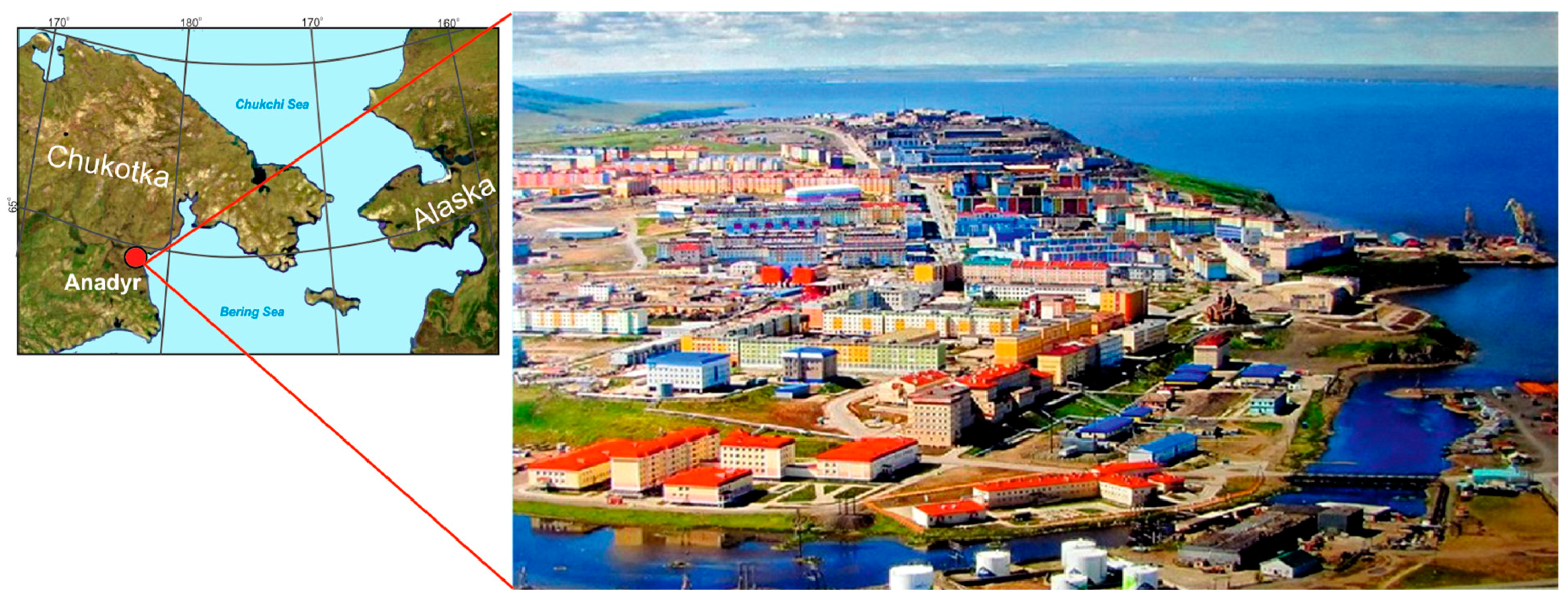
Anadyr is the administrative, logistical, and cultural center of the Chukotka autonomous district (Russia), located on the right bank of the Anadyr estuary, which belongs to the Bering Sea basin (
Figure 1).
The city is located on the northeastern edge of the Anadyr lowland within the boundaries of the southern shrub tundra. In relief, the building area occupies the southern and eastern slopes of the mountain with the peaks of Verblygiy (116.5 m) and Alexandra (131.2 m). From the north, the city is bounded by the rocky cliffs of the Anadyr estuary, and from the southeast, it is bounded by the floodplain of the Kazachka River. The permanent population of the city as of 2023 is 12,998 people. In the summer, due to seasonal workers and tourists, the number of residents increases to seventeen thousand people.
The climate of the Anadyr lowland is Subarctic marine, turning in a northwesterly direction into temperate continental. The climatic conditions are formed under the influence of cyclones penetrating from the Bering and Okhotsk Seas, as well as anticyclones that come from the Arctic and northern Asia. The main indicators of the climate and changes in their values in the XI century are shown in
Table 1. With an obvious warming of the climate and an increase in its humidity, it should be noted that the interannual fluctuations in the average annual air temperature reach 2 °C, the interannual amplitude of precipitation is 200 mm, and the duration of the frost-free period varies by an average of 5 days.
Anadyr is located in a zone of continuous permafrost distribution. The thickness of the permafrost rocks is 100–120 m. The temperature of the permafrost in undisturbed conditions varies from −5 to −2 °C depending on the relief and age of the frozen ground.
The depth of seasonal thawing in the tundra landscapes of the Anadyr lowland varies between 0.45 and 0.65 m. Over the past 25 years, it has increased by 30% [
41]. In floodplains and on mountain slopes, the thickness of the active layer is 1–1.5 m.
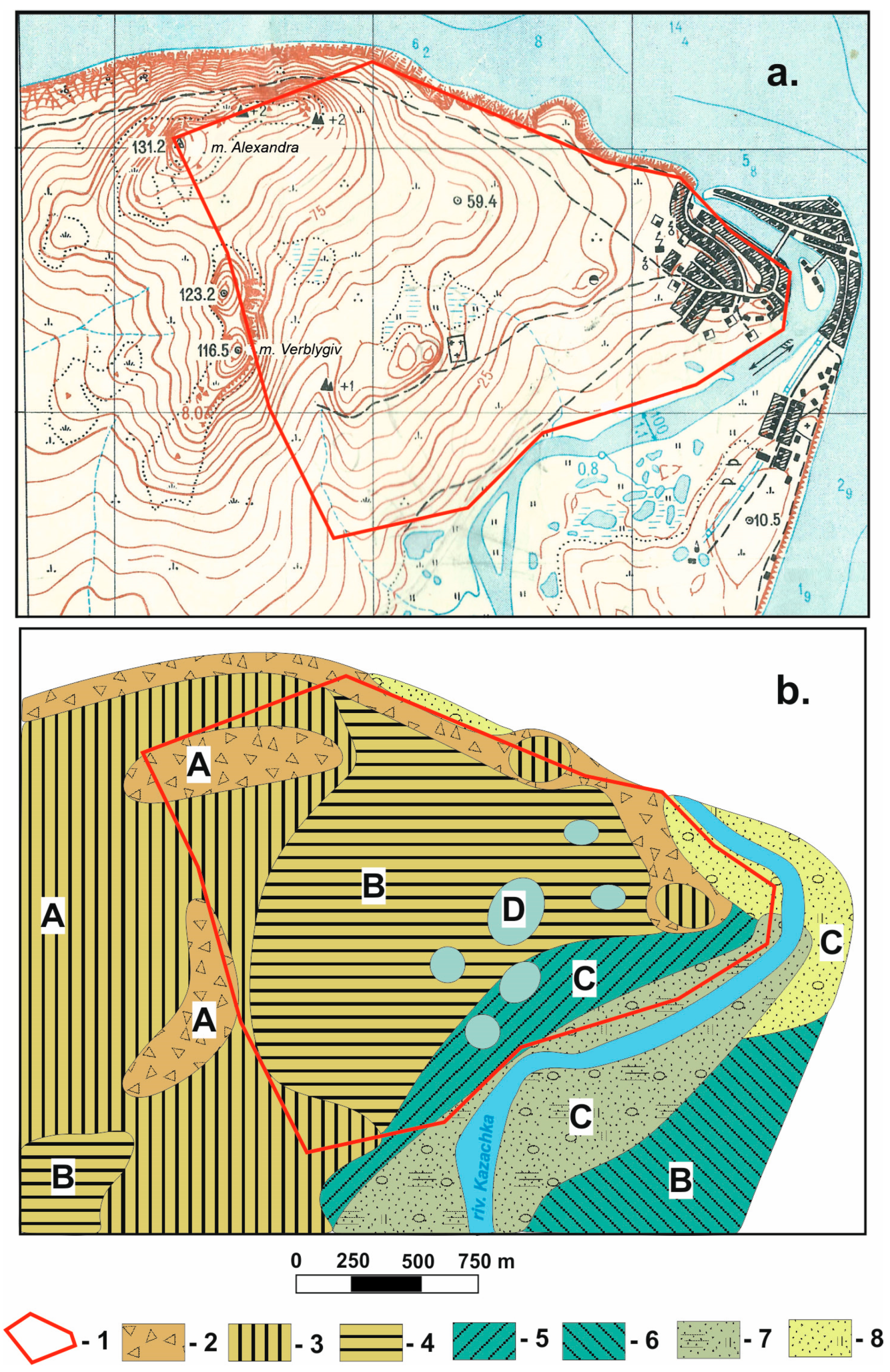
The urban development is located on the terraced slopes of the mountain (
Figure 2). The uplands are volcanic–tectonic protrusions of sedimentary and volcanic rocks of the Late Cretaceous, Paleogene, and Neogene ages. These are siltstones, andesites, and basalts. Along with the rocks of the intrusions and lavas, fragile tuffs and breccias of various geneses are often found in geological sections. Glacial, lacustrine, and marine Late Pleistocene deposits can be found by drilling in depressions and deep cuts to the Quaternary volcanic buried relief. The upper part of the geological section is composed of deluvial–colluvial, solifluction, and proluvial–alluvial deposits.
The modern territory of Anadyr was mostly built up in the 1980s and 1990s of the last century. The pre-construction relief is characterized by the presence of a high moor, ravines (tributaries of the Kazachka River), altiplanation terraces, and watersheds (
Figure 2a). Currently, this surface is buried by a layer of technogenic soil with a thickness of 1 to 15 m. The results of engineering surveys for construction are summarized in the permafrost–hydrogeological zoning scheme of 1991 (see
Figure 2b). The authors identified four hydrogeological zones that differed in the conditions of feeding and runoff of suprapermafrost waters [
42]. This diagram shows engineering and geological areas that differ in the geological structure of permafrost sections (see
Figure 2b).
The temperature of the frozen ground before the start of construction at a depth of 10 m varied from −4.4–(−3.8) °C in the upper part of the mountain slope to −2.6 °C at the mountain foot. At the bottom of the gorges, the temperature of the frozen soils reached −1.5 °C. In general, the builders noted a relatively low ice content of dispersed soils (up to 40%) with a wide variety of underground ice types: lenses and layers of segregation ice; vein ice in the cracks of rocks; and buried reformed ice wedges in lake and marine sediments. In 1985–1990, four talik zones of natural and man-made geneses were discovered and surveyed using geophysical methods (VES) and drilling. Two five-story buildings built in a passive way (I principle of construction on permafrost) were recognized as an emergency and demolished.
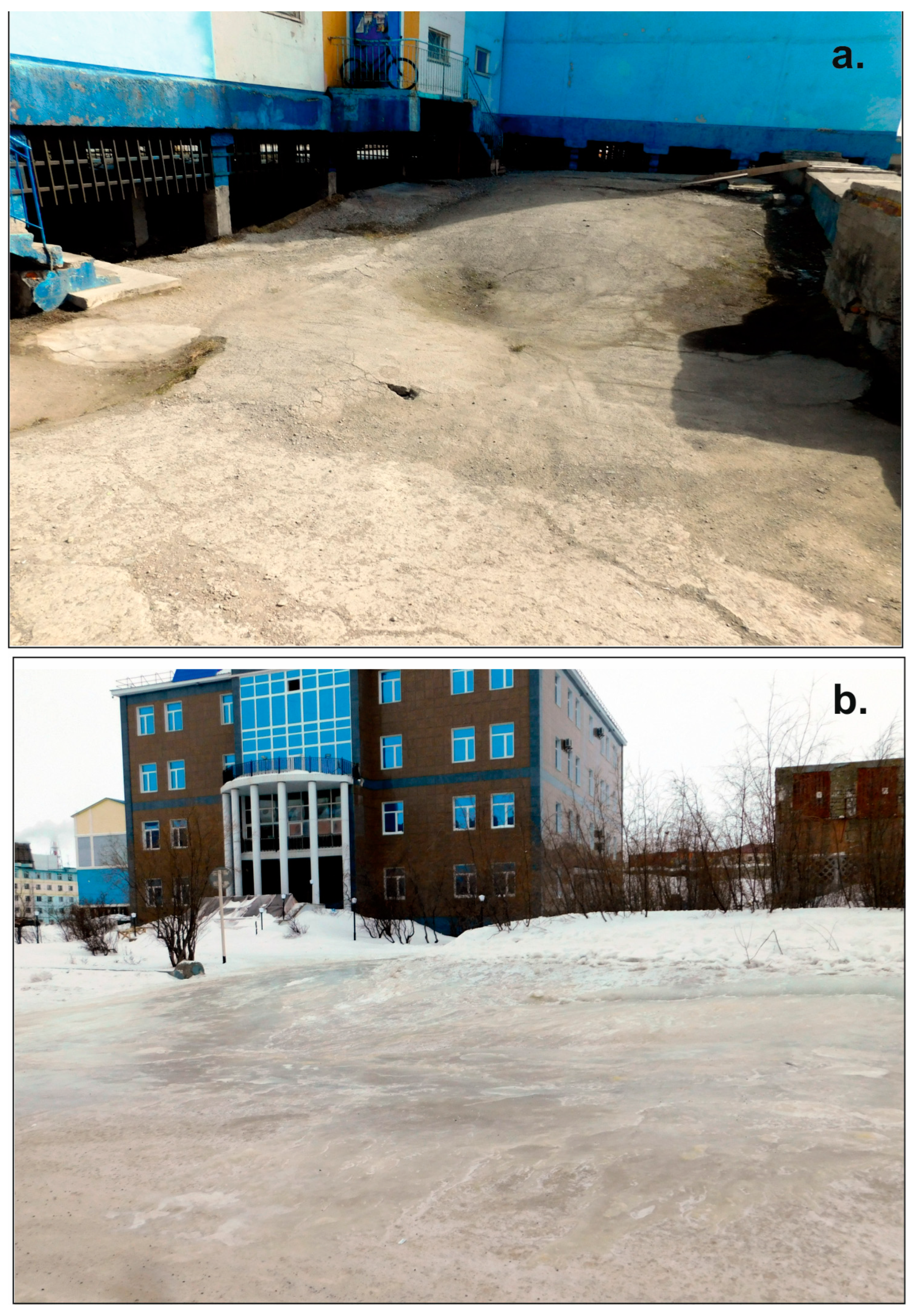
In 2003–2007, a large-scale reconstruction of the urban infrastructure was carried out. Utility networks and the road surfaces of streets and courtyards were replaced, dilapidated buildings were demolished, and the ventilated basements of buildings on pile foundations were cleared. The practice of the weekly cleaning of snow from Anadyr through the removal of solid precipitation outside the city limits was established. The foundations of deformed buildings were reinforced with metal ties and equipped with thermostabilizers. These measures had a positive impact on the stabilization of permafrost conditions, even during intense climate warming (1998–2007). According to the engineering survey materials of these years, the thickness of the active layer in the open space from the building stabilized within 1.2–1.4 m. However, there was an increase in 2018 in the number of deformations on the roads and the concrete surfaces under buildings on pile foundations, as well as in adjacent territories (
Figure 3a).
The number of icing fields increased, and the time and place of their formation changed (
Figure 3b). All of this pointed to the influence of climate warming on the activation of thermokarst and the expansion of the boundaries of talik zones. Currently, the area of the city is 3.45 km
2. The residential area covers 1.4 km
2, and the territory occupied by a thickness plant, construction, agricultural enterprises, and warehouses for various purposes in the northern and southern parts of the city accounts for 1.2 km
2. The rest of the territory is waste ground. There are 223 residential and administrative buildings in the city, built with the preservation of permafrost, on pile foundations with a ventilated underground. Of these, 155 buildings (70%) have five floors. There are 19 buildings equipped with thermostabilizers. Of the 172 observation wells preserved from construction geotechnical monitoring, 14 are flooded with water and 54 are filled with ice. (The requirements for observation wells in the cryolithozone in force in the USSR did not provide for the mandatory sealing of the casing base. Even a single thawing of frozen soils at the bottom leads to the filling of open wells with pressurized groundwater.) According to ground subsidence and the temperature measurements in wells, permafrost thawing has been detected under 17 buildings. The total number of seasonal icing fields, with an area of 75–4500 m
2, is unstable and varies from 4–6 to 12–18. The subsidence of soil and concrete coverings is confined to the underground of buildings, roadsides, roadways, and sidewalks.
According to the landscape position, relief, infrastructure, nature, and degree of the impact of climate change on permafrost, Anadyr is an ideal object for the implementation and testing of a monitoring system for urbanized territories. Using the example of Anadyr, it is obvious that, under conditions of a warming climate, permafrost geotechnical monitoring (which relies on monitoring the thermal effects of talik zones external to the foundations of buildings) will be the most effective method. The active spatial and temperature dynamics of the talik zones of the city will make it possible to develop monitoring technologies, interpret data, and forecast changes in permafrost conditions in a short period of time.
4. Research Methods
The main research methods were GPR subsurface sounding and geothermy of the upper permafrost layers. The physical foundations of the methods are described in specialized literature [
43,
44]. The application of geophysical methods in engineering geology is regulated by documents [
32,
37]. When planning the geophysical research, we took into account the methodological developments of the use of ground-penetrating radar in the cryolithozone, which researchers have shared in scientific articles [
17,
22,
23,
26,
30,
31,
34,
36,
37,
45].
However, in the selection of the equipment and parameters for GPR sounding and an area survey, we were primarily guided by our own experience of geophysical work in Chukotka within the framework of engineering surveys and scientific research. The most fully applied methodological techniques are reflected in [
46]. The adopted approach was based on the rejection of drafting cross-sections with the display of the exclusively electrophysical properties of the medium. The reason for this is the well-known dependence of the values of electrophysical parameters on the current physical properties of the sections (temperature, ice content, and ground moisture) and the uncertainty in the geological interpretation of the layers. The concept we chose was based on the use of reference geological and geophysical sections in the interpretation of radarograms, compiled using well columns and temperature measurements within them, as well as the definitions of the ice content and ground moisture [
46]. The number of reference sections used was determined by the geological and geocryological diversity of the mapped area. Subsequently, the results of the radarogram interpretation were selectively certified by control wells.
The studies were conducted between October 2021 and April 2024. Oko-2 and Oko-3 radars at frequencies of 400 and 250/700 MHz were used for the GPR profiling. The main frequency of the probe was 250 MHz. An antenna module with a frequency of 400 MHz was used additionally when profiling the boundaries of taliks in hard-to-reach places. The technical specifications of the devices can be found on the manufacturer’s page [
47]. Under the conditions of the Anadyr permafrost, when probing sites in the autumn–winter period, the devices demonstrated the following capabilities:
- -
400 MHz—maximum detection depth of 9–11 m and a resolution of 0.15–0.25 m;
- -
250 MHz—maximum detection depth of 17–20 m and a resolution of 0.3–0.5 m.
GPR profiling was carried out in the continuous mode, with a step of 300 mm, a dielectric constant of the medium (Ɛ) of 8, an accumulation of 16, and a sweep of 200. A length of the profiles from 50 to 150 m and a number of trails from 1000 to 3000 were determined in advance, depending on the conditions of the building. An important part of this work was the planning of profiles in order to evenly cover the area with GPR sensing points. The density of the city’s development made it possible to provide details corresponding to a scale of geophysical work of 1:10,000 (720 points/km2).
The primary processing of radar images was carried out using the GeoScan32 program (2023.01.27.728) [
47]. The processing of radarograms included the following:
Transforming the hardware length of the profile to its true length, setting the depth scale to zero, and adjusting the profile gain in depth;
Filtering the re-reflected waves and air interference and performing a hyperbola refinement of the dielectric constant of soils and the velocity of reflected waves along the length and depth of the GPR sensing profile.
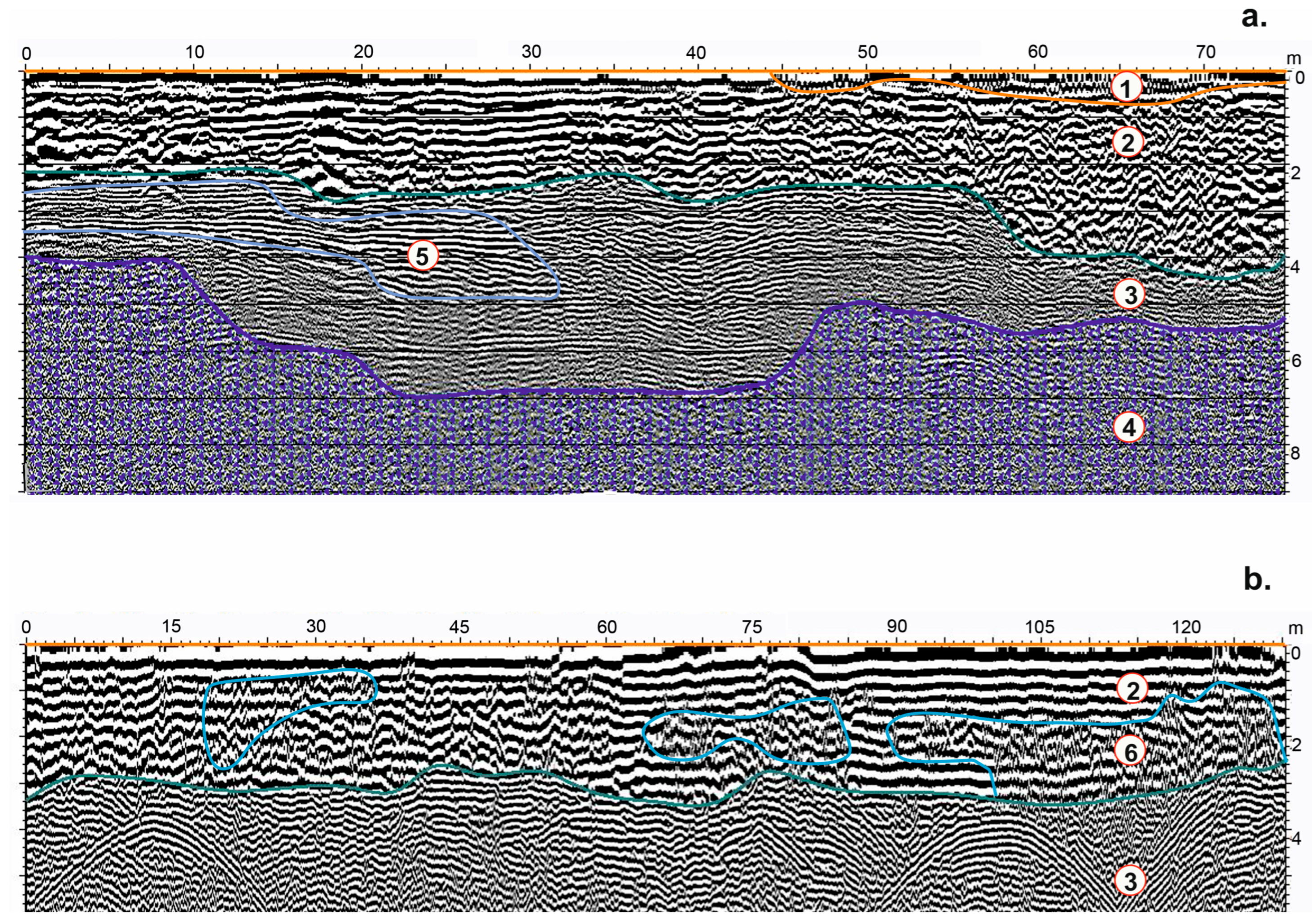
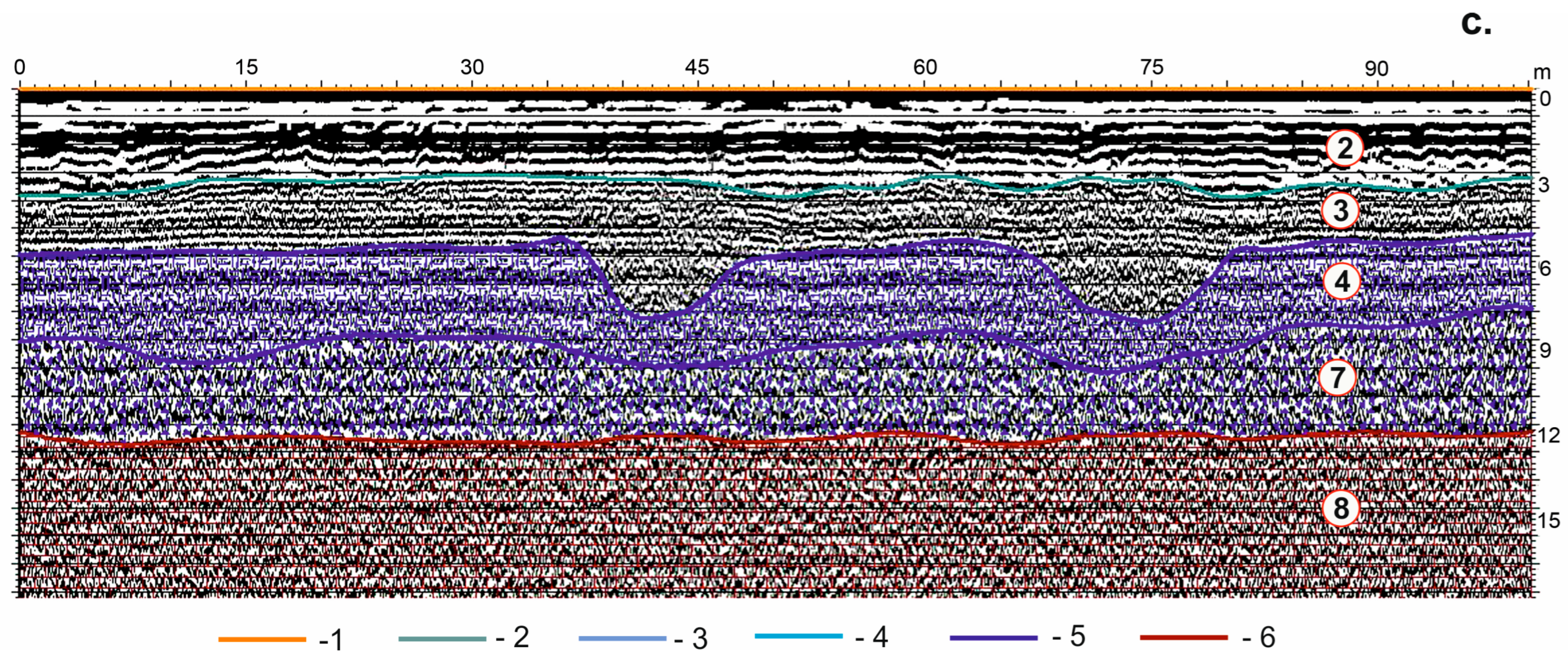
Within the framework of the tasks of this work, the hypsometric position of the beginning and end of the profiles was not determined. After the initial processing, the radarograms were interpreted by highlighting and clarifying the physical characteristics of the layers, the boundaries of which were drawn along the axes of the in-phase and along the bands of a sharp change in the wave pattern. Five reference geological and geophysical sections were used in the interpretation of radar images. To make a map of the talik zone distribution within the city, the following boundaries were identified on the geological and geophysical sections: the sole of the seasonal thawing–freezing layer and the roof of the permafrost layer. If there were signs of groundwater spreading, the boundaries of the suprapermafrost aquifer and its thickness were determined. The rest of the information available on the radarograms was not used in this study. It should be noted that the upper part of the geological and geophysical sections (permafrost roof) was rather monotonous in its physical properties and genesis (
Figure 4). The active layer, with a thickness of 1.5 to 4 m, was replaced with a depth in cutting by thawed and plastically frozen sandy–clay soil with a thickness of 0.5 to 6 m. Frozen sandy–clay and gravelly ground was beneath them. Frozen bedrock was present at the base of the sections at depths from 3 to 20 m from the surface. Aquifers were fixed in the thawed soil of the active layer, in thawed sandy–clay deposits, including on the border of the permafrost ground.
Further, the numerical values of the section parameters (depth and thickness of the layers) were taken manually and entered into a spreadsheet. The rejection of automatic data reading, the formation of spreadsheets, and the spatial modeling provided by the GeoScan32 program was due to the large size of the data array and the inevitable errors associated with the omission of anomalies or, conversely, their excessive detail. In manual mode, each profile was analyzed individually: small-in-width (up to 5 m) anomalies were ignored, and wide and deep anomalies were digitized in more detail. The matrix of the spreadsheet included columns with the number of the sounding profile, the rectangular coordinates of its location (X, Y), the values of the thickness of the seasonal thawing layer, the depth of the permafrost roof, and the thickness of the permafrost aquifer.
To measure the temperature in the wells, 4-channel devices for the automatic registration of the U12 temperature values from the Hobo Offset manufacturer were used. These logger data (U12) have proven themselves well in monitoring the temperature of the permafrost roof within the framework of the international CALM and GTN-P programs. The accuracy of the temperature measurements was to one-hundredth of a degree Celsius. During this work, 4 devices were used. In accordance with the depth of the observation wells and the length of the casing heads, the devices were equipped with cables (Thermistor chain) of 7.5, 10, 11.5, and 20 m long. The temperature sensors were located at intervals of 1.2, 1.5, 3, and 5 m. The algorithm of the operation was adopted as follows:
The condition of the well, its depth, and its suitability for measurements were determined in advance. A catalog of wells suitable for measurements (86 in total) was compiled, indicating the address of their location and depth. Wells with a depth of less than 5 m, as well as those located inside the underground of buildings or near thermosiphons, were rejected.
In November, under favorable weather conditions and at the beginning of the working day, logger programs were launched in the temperature registration mode after 1 min. Thermistor chains of different lengths were installed in wells of the appropriate depth to obtain measurements for 20–30 min (temperature stabilization time). The field log recorded the time of the installation and removal of the logger from each well.
At the end of the working day, the recording was stopped and the data were saved in a file with the appropriate date and time. Then, in accordance with the records of the measurement time in the log, the temperature of the ground at the appropriate depth was determined. The measured parameters were entered into a spreadsheet. After collecting the last of the measurements, the measurement data were recalculated in accordance with the temperature gradient for the depths of 3, 5, and 10 m.
The processing of the geothermal data resulted in a spreadsheet in which the well numbers, rectangular coordinates (X, Y), and soil temperature values as of November for the depths of 3, 5, and 10 m were indicated in columns. An important problem of geothermal research has become the uneven distribution of observation wells over the area of a city. For this reason, the southern outskirts of Anadyr (about 20% of the area) were excluded from the general territory of the geothermal research. The density of the observation points within the boundaries of the ground temperature spatial monitoring was about 32 wells/km2, which corresponds to the scale of work of 1:25,000. The spatial modeling of the GPR profiling and geothermy data was carried out using the Surfer 12.8.1009 program. The spreadsheets were loaded into the program and processed using the Kriging method. The results of the spatial modeling were presented in the form diagrams of isoclines for the corresponding parameter values.
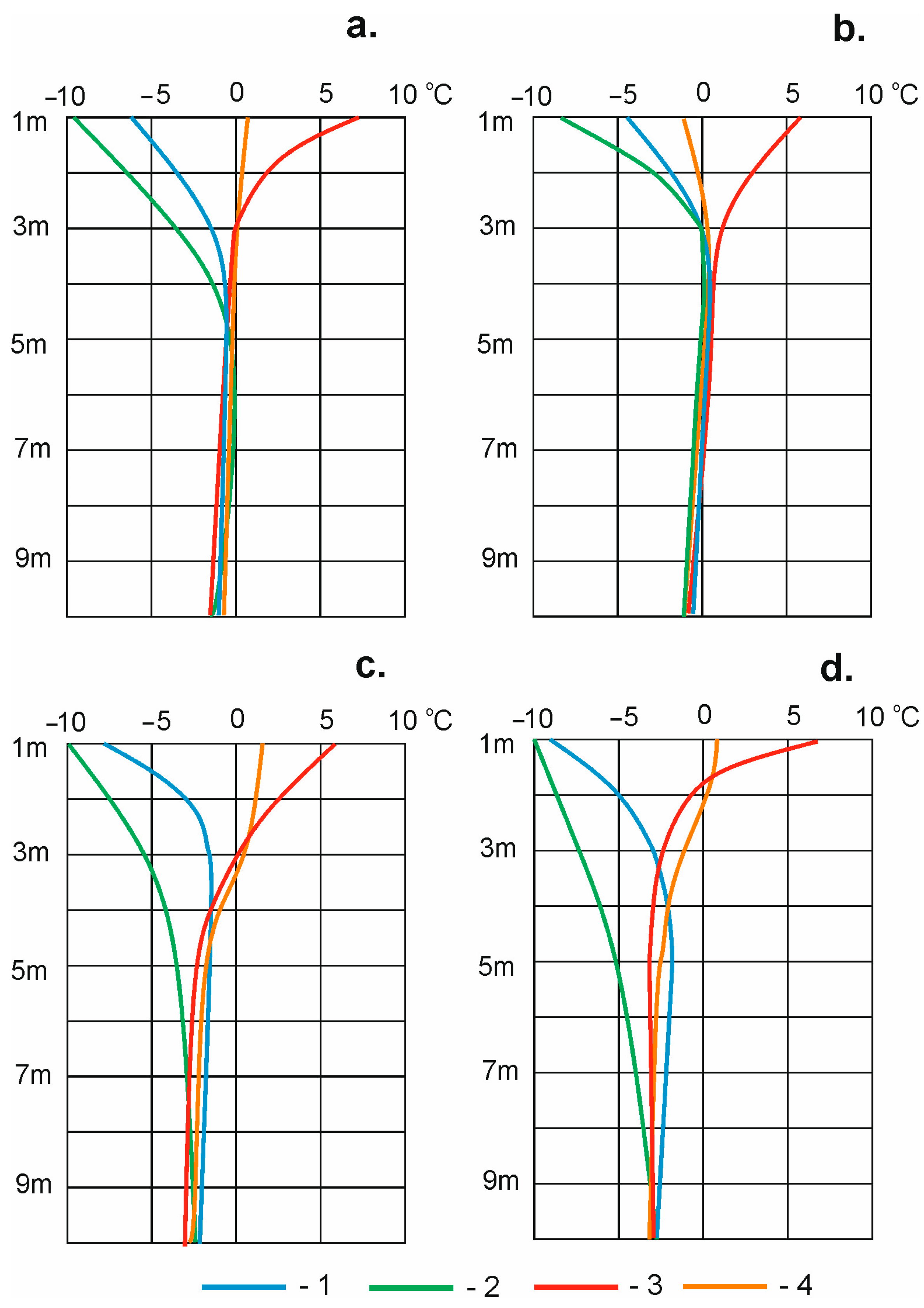
The revealed spatial anomalies of the thawing ground’s capacity were successfully verified by drilling 6 wells. The correctness of the selection of criteria for hazardous talik zones and approaches to the interpretation of radarograms was confirmed by the soil temperature measurements from the verification and observation geothermal wells. In the talik zones, the depth of seasonal freezing (thawing) reached a maximum of 4–4.5 m. Below were thawed soils with a capacity of 2–3 m, and cooled plastically frozen soils were located in the depth range of 7–10 m (
Figure 5a,b).
Under the background conditions of permafrost preservation, the depth of seasonal thawing was 1.8–2 m. Starting from a depth of 3 m, frozen soils were found in this section (
Figure 5d).
While in contact with the talik zone, the depth of seasonal thawing increased to 3 m. In the depth range of 4–6 m, the soil cooled to −2.2 °C only by the end of the winter period, and then the soil temperature rose to −1.45 °C, which corresponded to a plastic–frozen state (
Figure 5c).
5. Research Results
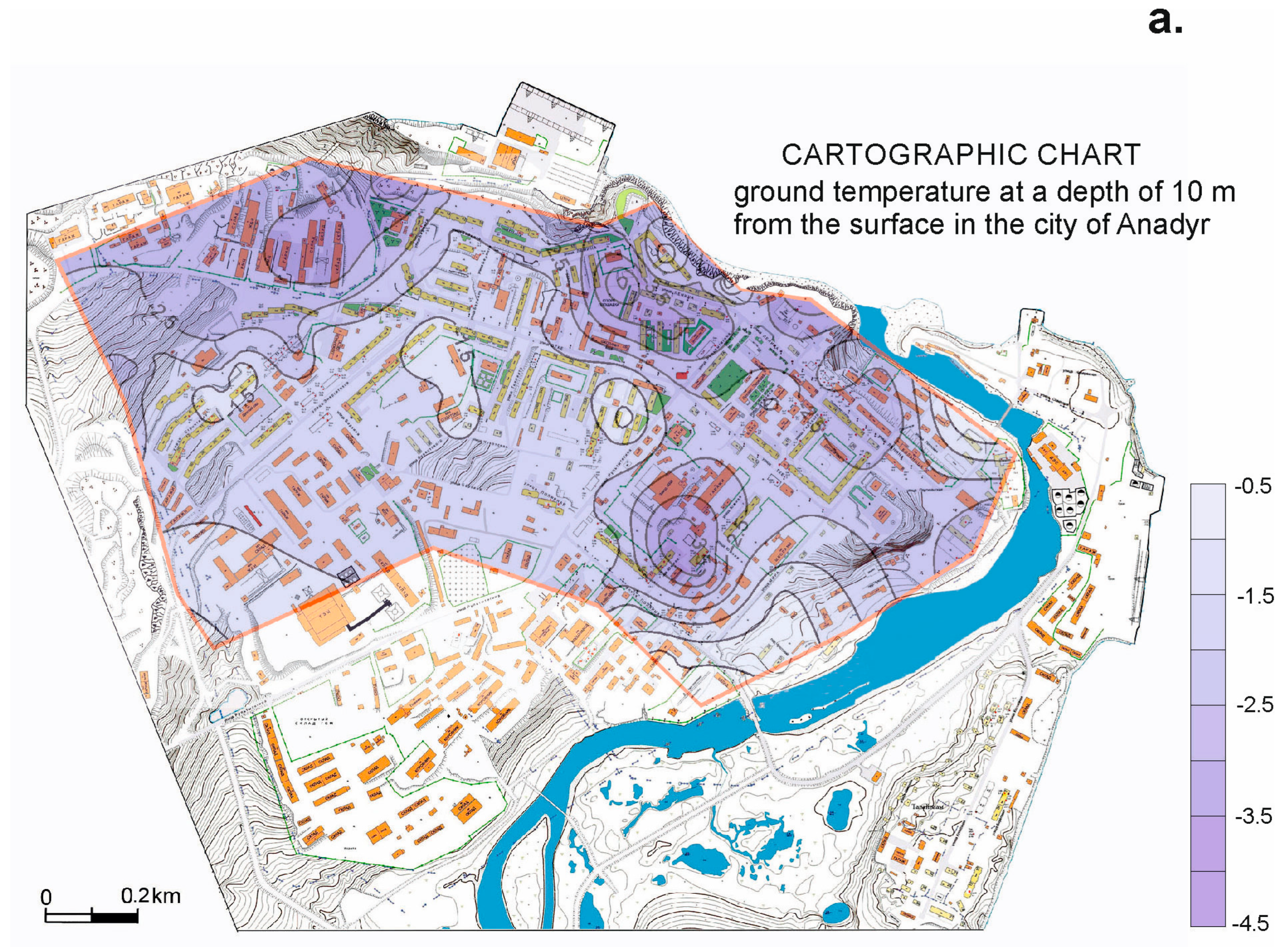
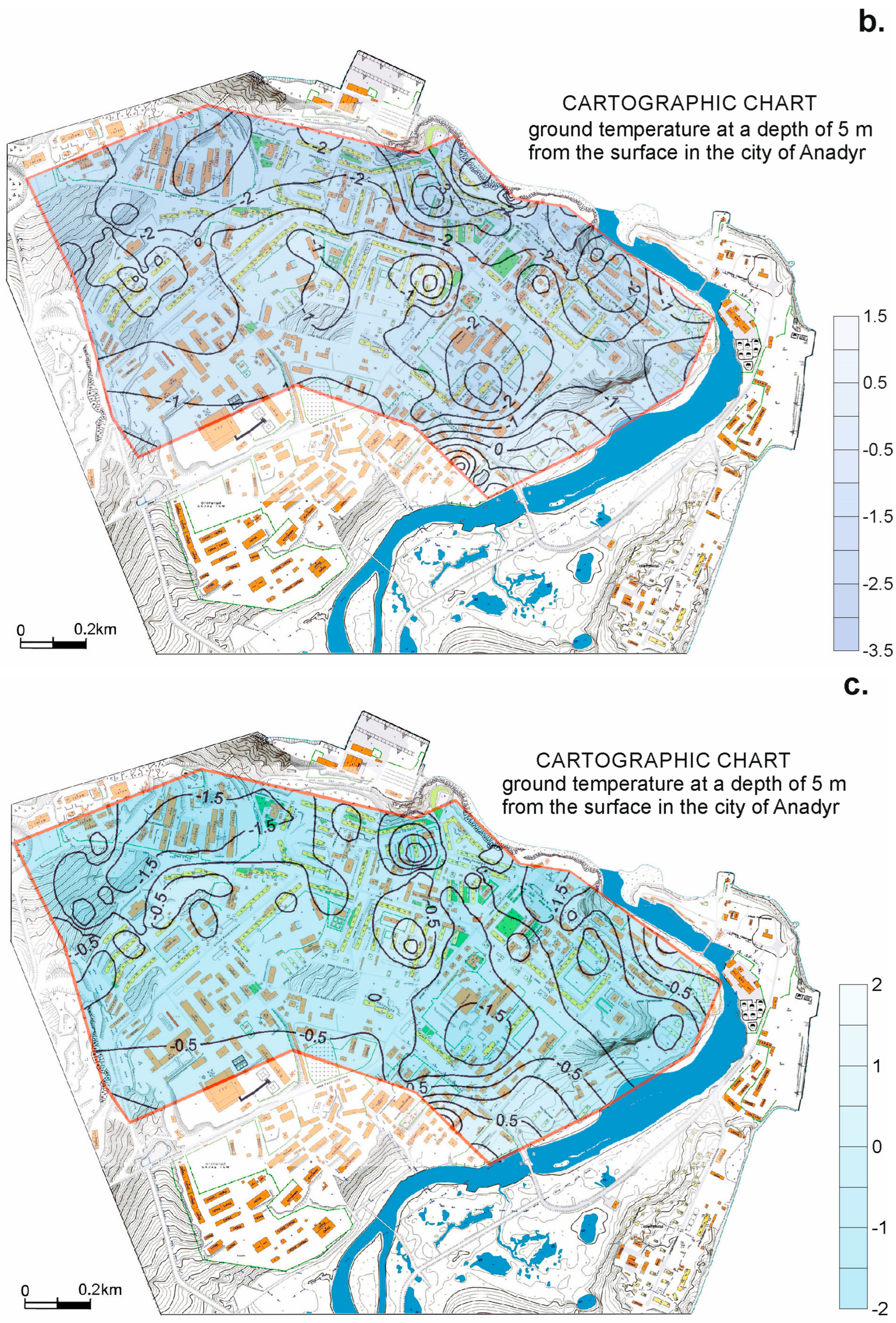
Due to the low density and uneven distribution of observation wells over the city area and the fact that most of them were confined to the perimeter of buildings, the geothermic studies had a reconnaissance character. The results are presented for the spatial modeling of the soil temperature in the wells of ground temperature fields constructed for imaginary cross-sections at depths of 3, 5, and 10 m from the surface (
Figure 6).
The deepest cross-section showed the general trends in the temperature of permafrost within the boundaries of the urban landscape. The lowest temperatures, in the range of −2.5–(−3.5) °C, were recorded in the northwestern and northeastern outskirts of the city, as well as in the eastern half of the residential area. The general trend of increasing soil temperature at a depth of 10 m to −0.5 °C had a southerly direction. This was somewhat different from the geotemperature pattern of the 90s, when the soil temperature increased from northwest to southeast (from −4.4 to −1.5 °C). Obviously, these changes are largely related to the formation of a layer of man-made soils during construction, and in fact, a layer of newly formed frozen soils exists in modern times. This is confirmed by the fact that cold anomalies tend to occur in areas where rocky soils, andesites, and basalts lie close to the surface and the thickness of man-made soils is minimal. Simultaneously with technogenic changes in the structure of the permafrost roof, climate warming has led to an increase in seasonal thawing and the thickness of the annual temperature turnover layer from 10–12 m to 12–16 m.
The most extensive positive anomaly, limited by the isotherm of −1.5 °C, was confined to the floodplain of the Kazachka River and the buried bed of the left tributary (
Figure 6a). It was divided by rocky ground with a temperature of −3 °C. The same anomaly in size and sign was located in the western part of the studied territory. It was detected in areas that have experienced the heavy dumping of man-made soils (6–15 m).
Point anomalies in the central part of the urban development on the surface corresponded to the modern subsidence of soil and concrete coatings.
The temperature field of the soils at a depth of 5 m generally followed the contours of the anomalies of a 10 m cross-section, but differed in higher temperature values: from −3.5 to 1.5 °C. At the same time, as expected, cold anomalies were localized with a decrease in the depth of the slice, and warm anomalies in the city center expanded and complicated their morphology (
Figure 6b).
The temperature field closest to the surface of the 3 m cross-section reflected the dynamics of modern cryogenic processes. The soil temperature varied from −2 to positive 2 degrees Celsius. The isotherm of −0.5 °C in relief ran along the middle part of the slope of the southern exposure. There were no spatial trends in the soil temperature changes within the contours of the residential area. Here, against the general background and with a temperature of −0.5 °C, there were quite large anomalies with a ground temperature in the range from −1.2 to −2.0 °C. In the northeast of the city, such an anomaly was confined to the basement sea terrace. On the northwestern outskirts of the city and in its center, the contours of the anomalies of the city were recorded by shallow buried lava basalts. These patterns indicated that the permafrost roof is now cooling from below due to the better conductivity of cold in rocky soils from the permafrost to the surface. The number of positive anomalies on the map increased compared to the 5 m cross-section. Local positive anomalies with temperatures above −0.5 °C were grouped and formed chains down the slope or along streets oriented in the cross of the slope. The most contrasting positive temperature anomaly (up to 2 °C) corresponded to the buried bed of the left tributary of the Kazachka River.
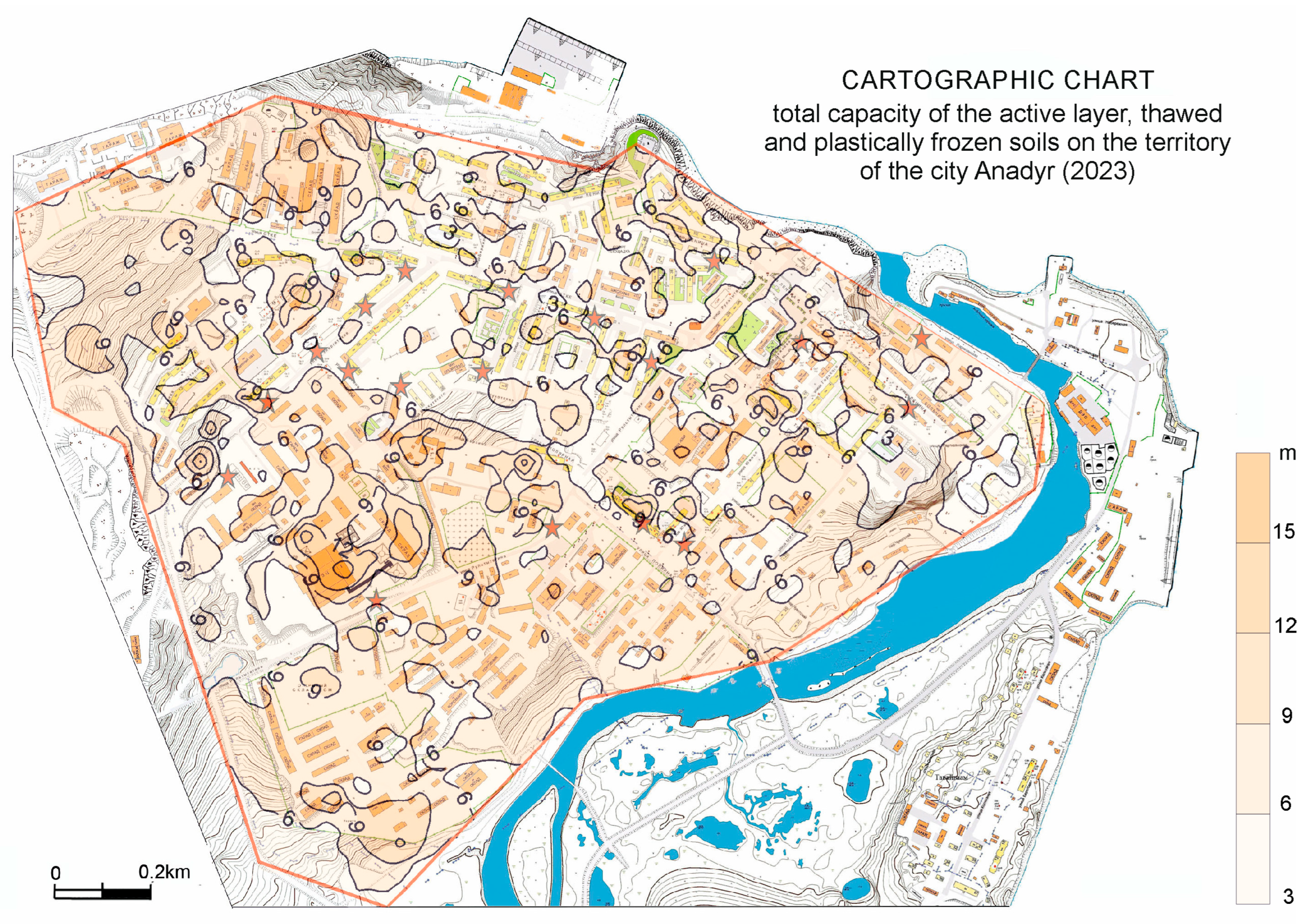
The main result of GPR profiling was the mapping of the depth of the permafrost (
Figure 7). The total capacity of seasonally thawed (seasonally frozen), thawed, and cooled plastically frozen soils in the territory of Anadyr ranged from 2 to 18 m. The structure that isopachites formed on the map was complex. The residential zone was divided, where the background for anomalies was the depth of the permafrost (3–6 m), and, in the outskirts of the city in the south and northwest, the normal thickness of seasonally thawing and plastically frozen soils was 6–10 m. In the most elevated part of the city, on vacant lots and in industrial zones, the anomalies were extensive. Further down the slope, at the entrance to the residential area, wide anomalies were divided into many linear flows with inflations and bifurcations. Outside the residential area, in the lowest part of the city, the anomalies combined again and formed a kind of plume. In the residential area, the anomalies were contrasting; in most cases, they had linear outlines and were oriented downhill. The most contrasting and significant anomaly in the depth of the permafrost was located within the boundaries of the production zone of the Anadyr thickness plant, where the capacity of man-made soils was 10–15 m.
A significant portion of the linear, downhill-oriented anomalies were confined to streets and mainline utilities. The expansion of anomalies was recorded at the intersection of streets located in the cross of the slope. Bifurcation points were spatially correlated with groupings of storied buildings with ventilated pile foundations, as well as rocky ground lying near the surface. The modern subsidence of the soil and concrete coatings, as well as of the icing field, was located on the periphery of the anomalies.
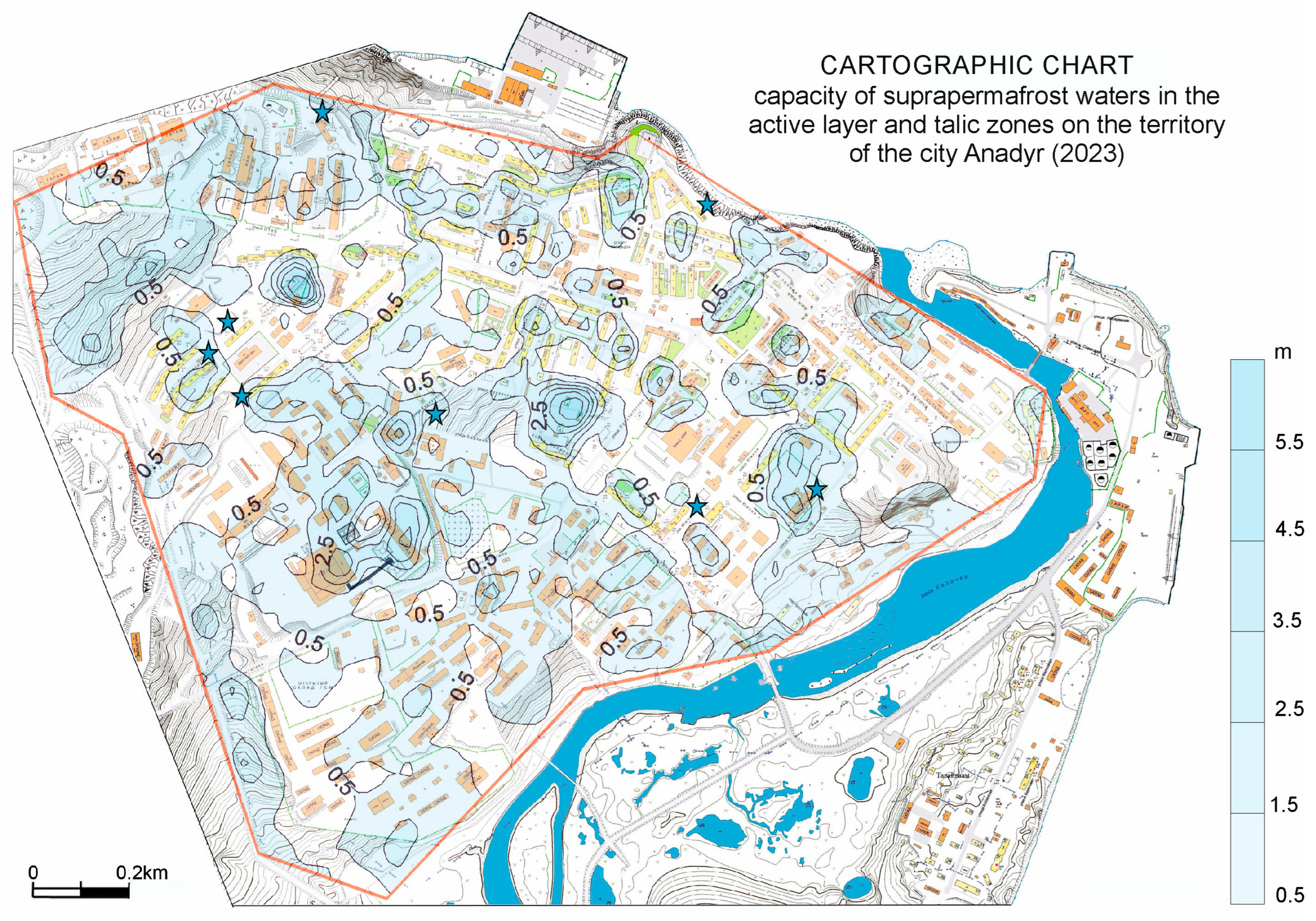
The most informative result from the point of view of understanding the modern picture of the exogenous cryogenic processes is a cartographic diagram of the total capacity of the suprapermafrost waters in the active layer and the underlying thawed sandy–gravelly ground of talik zones (
Figure 8).
It should be noted that, in urban spaces, the contours of the anomalies in the depth of the permafrost and the capacity of the horizon of permafrost waters rarely coincided. Usually, the thickness anomalies of the above-frozen waters were somewhat offset from the thickness anomalies of the thawed layer. The reason for this is the spread of waterproof clay deposits in the taliks, as well as the runoff of underground suprapermafrost waters. GPR profiling recorded the result of the summer–autumn redistribution, or, rather, the runoff of suprapermafrost waters. The contrasting pattern of anomalies indicated the active dynamics of permafrost waters.
As in the case of anomalies in the depth of the thawed layer, linear anomalies of suprapermafrost waters were confined to roads oriented in the direction by the slope of the terrain and by active and buried ravines. In the northwestern outskirts of the city, a non-contrasting anomaly was recorded in an area with preserved natural soil and vegetation cover. The same non-contrasting anomalies were observed on the slope of the southern exposure with low-rise buildings. Most of the anomalies of the aquifer with a capacity of 2.5–3 m were located in areas with a thick layer of up to 6–12 m of gravelly soil on construction sites. This indicates the validity of our assumptions about the feeding of talik zones with condensation waters. Icing fields were confined to the periphery of anomalies or located in places of the narrowing (pinching) of the isopachites of permafrost waters.
6. Discussion
The patterns of distribution for the territory of Anadyr, the soil temperature at various depths, and the spatial dynamics of the capacities of thawing soils and suprapermafrost waters allowed for a number of reasonable assumptions to be made, taking into account the knowledge of geomorphology and the general patterns of the geological structure of the city.
The zones of “cold” permafrost tended to be located in areas with the low-thickness dumping of man-made soils and the shallow occurrence of waterproof rocky rocks. Areal warming of the permafrost roof was observed on the southern slope of the built-up area, in areas of distribution in the geological section of marine and continental sediments. Local anomalies of “warm” permafrost were confined to buried streams and swamps.
The most contrasting anomalies according to the capacity of thawed ground were located in a residential part of the city with densely placed apartment buildings and a network of utilities and roads. On the outskirts of the cities with low-rise buildings and vacant lots, non-contrasting areal anomalies were widespread. The suprapermafrost waters were spatially correlated with the depth of the ground melting. The anomalies of the capacity of suprapermafrost waters were most structured in terms of their morphology and location in space.
The factors that determined the location of talik zones and had an impact on their development were divided into natural and man-made. Among the natural factors, geological, geomorphological, and climatic factors were distinguished. The geological structure of the territory influenced the configuration of taliks through the distribution of igneous and sedimentary rocks of various ages, temperatures, and water permeabilities in the geological section. The geomorphological factors included the slope of the surface of the modern and buried relief and the permafrost roof, as well as buried ravines and streams, swamps, the sea, and river terraces. The climatic factor was realized through different exposure levels of slopes in the absence of surface shading by tall buildings, and through favorable conditions for air circulation in the summer and the preservation of snow cover in the winter.
Among the technogenic factors influencing the formation and evolution of talik zones, the following are included:
The thickness and conditions of filling the surface with gravelly soil;
The removal of snow from roads, streets, and courtyards;
Orientation in the space of main streets and utilities, and the location of buildings with a ventilated foundation and thermostabilizers in the urban area.
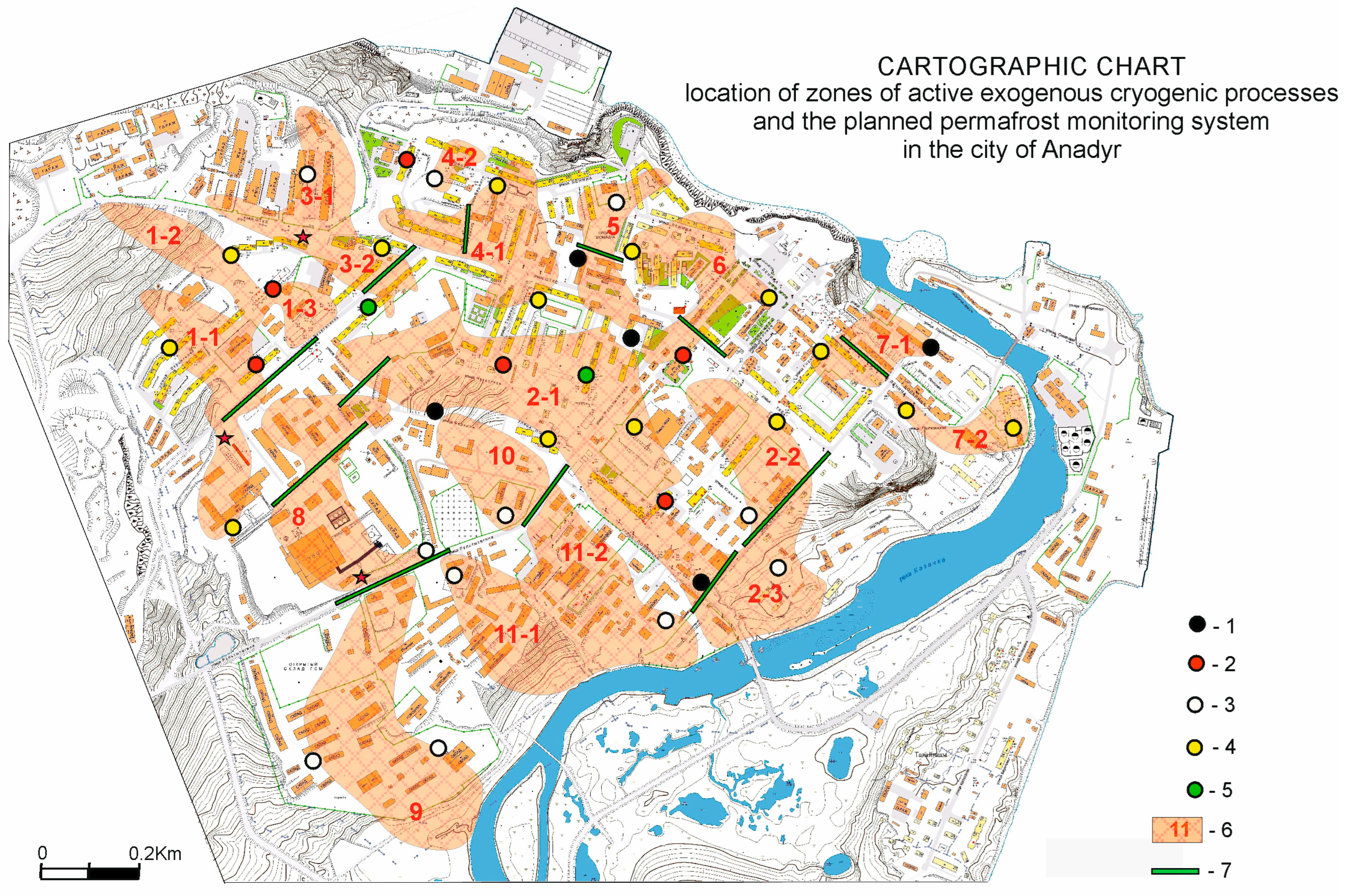
Collectively, the naturally oriented anomalies of the thickness of thawing soils and suprapermafrost waters located in the area of elevated ground temperatures were grouped, and they represent the hydrogenic zones (20 zones) of the dangerous development of exogenous cryogenic processes (
Figure 9). These zones are dynamic, are influenced by climatic and man-made factors, have an alimentation area, and involve the unloading of groundwater. Along with them, there were relatively isolated and static anomalies of the thawed layer, the nature of which was due to the inherited development of the natural taliks of stagnant waters, which were discovered even before the start of construction [
42].
Our proposed permafrost-monitoring system for the city of Anadyr consists of an automated network of soil temperature observations in observation wells and 12 control georadar profiles, located in the strike zone and along the border of 20 zones of the development of dangerous exogenous cryogenic processes (see
Figure 9). The network is planned to consist of 35 observation wells with a depth of 10.5 m. Temperature recordings at depths of 1, 3, 5, and 10 m will be performed every 6 h. The measurement data will be automatically transmitted over mobile communication to the central server. Next, the data will be processed and presented in the form of graphs and charts. Control profiles will be produced annually at the end of the warm season. The results of the GPR of the control profiles will be presented in the form of geological and geophysical sections. The permafrost-monitoring system also includes visual observations of the subsidence of ground and concrete coverings, and the icing field of groundwater.
In 2023, an experimental segment of the automated soil-temperature-monitoring network was created and is operating; it consists of six wells and 24 sensors. The completion of the permafrost-monitoring system and the start of systematic observations is planned for 2025–2026. The total cost of creating a permafrost-monitoring system in the city of Anadyr will amount to USD 250,000. The annual cost of maintaining the monitoring system will be about USD 15,000. In the future, the system is expected to become more complex due to the formation of subsystems of industrial enterprises and individual residential neighborhoods in areas of the dangerous development of negative processes.
Thus, in our reasoning, we return to the beginning of the article, when we raised the question of what should be the system of permafrost geotechnical monitoring in the settlements of the cryolithozone. Based on the research conducted in Anadyr, the answer is obvious. It is easier, more efficient, and more cost-effective to control the dynamics of the development of 20 dangerous talik zones than the perimeter of the foundations of 223 residential and administrative buildings of the city. This conclusion is also based on the fact that building monitoring is aimed at passively protecting the foundation base from thawing, and monitoring hazardous areas is focused on localizing the negative impact of the talik front on permafrost in the foundations of buildings and engineering structures. At the same time, the proposed monitoring system, which is important, covers roads and the heating, electrical, and water supply communications of the site under observation.
Another important issue concerns the methods of monitoring the zones of development of dangerous exogenous cryogenic issues. The results of our research provide an answer to this question. The year-round, continuous, and automatic monitoring of the ground temperature regime in the center and along the flanks of dangerous zones should be combined with the annual GPR profiling of taliks in order to control their geometric parameters in informative areas (see
Figure 9). The algorithm of the research aimed at substantiating and creating a system of permafrost monitoring of settlements is also clear: an analysis should be conducted to gather information about the geological structure, geomorphology, and infrastructure of the settlement; measurements of the soil temperature should be collected from existing or specially drilled wells; surface deformations should be documented; areal GPR profiling should be performed on a scale of at least 1:10,000; and computer spatial modeling of the parameters of talik zones should be conducted.
7. Conclusions
In our research, we showed the relevance of the problem of creating a permafrost-monitoring system in Arctic and Subarctic settlements. The main problems of choosing the approaches to monitoring the degradation of permafrost in urbanized areas were identified. Using the city of Anadyr as an example, new approaches to substantiating the permafrost-monitoring network were proposed and tested and the technology, methods, and sequence of the work were described.
As a general conclusion of the work, it should be noted that it is necessary to quickly create a circumpolar system for monitoring permafrost degradation in urbanized areas as part of an adaptation to climate change. This system should be primarily focused on the safety of the population. Another task of permafrost monitoring is to ensure the functionality of the existing infrastructure of settlements during the transition period of permafrost–climatic transformation. For the cross-border dissemination and implementation of the urban permafrost-monitoring system, an open discussion by the scientific community on the proposed approaches and methods and on the experience in creating local systems under specific climatic and technogenic conditions is necessary. The presented research was devoted to this.
