Article

Static and Dynamic Evaluation of an UWB Localization System for Industrial Applications

1
Normandie Univ, UNIROUEN, ESIGELEC, IRSEEM, 76000 Rouen, France
2
SIAtech SAS, 73 RUE MARTAINVILLE, 76000 Rouen, France
*
Authors to whom correspondence should be addressed.
Submission received: 18 September 2019 / Accepted: 28 October 2019 / Published: 3 April 2020

Abstract

:
Many applications in the context of Industry 4.0 require precise localization. However, indoor localization remains an open problem, especially in complex environments such as industrial environments. In recent years, we have seen the emergence of Ultra WideBand (UWB) localization systems. The aim of this article is to evaluate the performance of a UWB system to estimate the position of a person moving in an indoor environment. To do so, we implemented an experimental protocol to evaluate the accuracy of the UWB system both statically and dynamically. The UWB system is compared to a ground truth obtained by a motion capture system with a millimetric accuracy.

1. Introduction

Robotization, especially in factories, leads to an increasingly close interaction and collaboration between man and machine, a concept referred to cobotics. This evolution is accompanied by a growing demand for intuitive and efficient Human Machine Interfaces (HMIs) based on natural interaction. In this context, HMIs will have an effect on the development of innovative handheld human-machine interfaces relying on gesture recognition to enable intuitive and non-intrusive control of industrial machinery. To achieve this task, accurate and tiny form-factor sensors are required. Operators can move freely in a building, or a workshop without being constrained by having a cumbersome locating systems. The capture of the movement or the posture must be coupled with a notion of accurate and absolute location in a building (workshop, warehouse); this information enables a natural and contextual interaction between the operator and a set of machines. Localization in indoor environment, which be used in industry 4.0 and industries of the future, correspond to a new way of organizing the means of production. Those future industries are emerging as the convergence of the virtual world, digital design, management (finance and marketing) with real-world products and objects.
Observation and understanding of gestures and posture have been the subject of numerous studies. Many studies were presented regarding gesture perception from a fixed sensor [1], the best known being the Kinect from Microsoft [2]. However, all these solutions restrict the movements of the operator and limit the possibilities of natural interaction with a machine, such as the distance or the field of view for everyday use. Another approach is to observe movement from a hand-held device. These solutions are generally based on inertial sensors such as accelerometers and gyroscopes; their assembly forms what is commonly called an IMU (Inertial Measurement Unit) [3]. IMU diffusion has increased with the development of MEMS (Micro-Electro-Mechanical Systems) technologies, which offer good cost-to-performance ratios and are well adapted to human proportions [4,5].
These solutions are the basis for Attitude Heading Reference System (AHRS) measurement devices. They are attitude measurement units because they allow a measurement of the orientation of the sensor in the terrestrial reference frame, a measurement that can be significantly improved thanks to the most well-known data fusion algorithms Magdwick [6] and Mahony [7] which are nonlinear complementary filters. The majority of these methods use an Extended Kalman filtering (EKF) [8]. A review of these filtering methods and the performance that can be achieved today with low-cost MEMS sensors can be found in [9].
Indoor localization solutions based on radio-frequency systems are equivalent to a GPS. These solutions incorporating are being studied using trilateration methods and a transmitter-receiver distance information, known as RSSI for Received Signal Strength Indicator. The RSSI is available in many telecommunication standards. The use of RSSI values requires a model that relates power attenuation to distance, which is complex in concrete practical situations. It suffers from poor localization accuracy (notably in non-line-of-sight conditions) due to additional signal attenuation resulting from transmission through walls and other daunting obstacles and can need fingerprinting. More recently multilateration (measurement from transmission time differences called) Time Difference of Arrival or TDoA between at least three transmitters is needed to calculate the exact location of the receiver. The fact that the system to be located is itself active considerably increases localization accuracy. There is a wide range of systems in this field. TDoA estimation accuracy depends (similar to the ToF techniques) on the signal bandwidth, sampling rate at the receiver and the existence of direct line of sight between the transmitters and the receiver. Strict synchronization is also required, but unlike ToF techniques where synchronization is needed between the transmitter and the receiver, in the TDoA case only synchronization between the transmitters is required. TDoA does not require any fingerprinting, does not require clock synchronization among devices and the reference node. A review of these solutions shows that an accurate localization around 30 cm is possible [10,11]. However, this performance degrades severely when there is no direct Line-Of-Sight between the terminals (fixed anchor in the building) and the receiver (tag placed on the moving person). The accuracy of these solutions depends on the environment where the system will be deployed, which is related to the use case. It should be noted that there is a great anticipation caused by the release of Ultra WideBand (UWB) radio solutions on the market, which promise to be even more efficient than those currently available. The feature of UWB that makes it interesting for use in localization is its wide bandwidth, that allows better discrimination of multipaths and better estimates of flight time in indoor environments compared to other RF technologies such as Wi-Fi.
This work contributes a dynamic test with a millimeter accuracy ground truth in real time, to evaluate its precision and its accuracy.
This paper is divided into two parts. First, we study the performance a UWB-based localization sensor named “UWB” ; in the second part of this paper, we evaluate specific aspects of a free space including metallic objects such as robots, structures or doors in our laboratory. Secondly, we propose a complete evaluation of the system behaviour in static and dynamic conditions to see if UWB can be used to obtain an accurate 3D trajectory.

2. Survey of Different Indoor Localization Technologies and UWB

2.1. Indoor Localization Systems

For human–machine interaction in the context of industry 4.0, it is necessary to be able to locate the operator in a wide environment (above 20 m range) and with good accuracy (with a 0.1 m accuracy). Localization in an indoor environment will be used in industry 4.0, based on Mautz’ thesis [10,11] there are 13 technologies shown in Table 1 that can answer indoor localization.
Systems based on cameras for indoor localization approaches are used in different ways. The first one is to have a 3D building model as a reference. There is no need to have reference nodes substituted by a digital reference point list. These systems have the potential for large-scale coverage without significant increase of costs and have a decimeter level of accuracy [12,13]. The second system is the so-called view-based approach. It consists of taking the common view of a mobile camera and comparing it with previously captured view sequences. This system managed at centimeter accuracy and can cover a building [14,15]. The third system is coded targets, used for point identification to locate a person. The system can know where the person is with a centimeter accuracy but does not store the trajectory made by the person [16]. The fourth system is the projection of reference points in the environment. This system needs a direct view of the same surface and it can be used for tracking and scene reconstruction with a millimeter accuracy [17]. The fifth system is using one camera or many cameras without reference by observing position change. This system can reach sub-centimeter accuracy and can cover 30 m2 [18]. The use of a camera for our application is limited to the view of the camera. The camera may be covered with clothing or dusts and therefore lose its position, which can affect safety and security. UWB is better in this case because it can work when covered.
Infrared systems based on active beacons or using natural radiation are mainly used for rough positional estimation or for detecting the presence of a person in a room. They have centimeter-meter accuracy levels and can cover 1–5 m in static conditions. They are a common alternative to optical systems operating in the visible light spectrum. An accuracy of 4 cm has been reported and people can be tracked up to a distance of 5 m [19] and centimeter accuracy in a retail store [20]. The multipath errors reduce drastically the localization accuracy, IR technology requires a Line of Sight (LoS) between transmitter and receiver to function properly. In industry, LOS is unexpected, which is why the UWB system is more interesting, as it uses radio frequency and has a wide bandwidth that can handle NLOS.
Tactile and polar systems have µm-mm accuracy and can cover an entire room. The polar point method uses a distance measurement and an angular measurement from the same beacon to determine the coordinates of a nearby station. Tactile systems are high precision mechanical instruments which measure positions by touching an object with a calibrated pointer. It is practically unfeasible to track an entire trajectory in 3D [10] with tactile system. Polar systems are really expensive compared to UWB systems and need a direct line of sight to have the greatest accuracy.
Localization systems based on propagation of sound waves have a centimeter accuracy and can cover 2–10 square meters, using the Time of Flight localization technique. The sound is a mechanical wave so positioning systems use air and building materials as means of propagation [21,22]. The acoustic waves are affected by sound pollution, that means in industry with several machines cause sound noises, accuracy will be affected. UWB systems are immune due to its wide bandwidth (3.5–6.5 GHz) [23].
WLAN/WIFI systems include accuracy in order of one meter and can cover 20–50 m2. Distance estimation using WLAN is altogether possible from RSSI (Received Signal Strength Indication), ToA (Time of Arrival), TDoA (Time Difference of Arrival) and RTT (Round-Trip Time). Recent WiFi-based localization systems [24] have achieved median localization accuracy as high as 23 cm [25]. Wi-Fi systems are prone to noise and require complex processing algorithms. The accuracy of this kind of system is not enough to handle an accurate trajectory estimation in NLOS industrial indoor environments in our case [26,27]. UWB is interesting thanks to its wide bandwidth which makes it more accurate in industrial warehouses.
RFID could be used and has dm-m level of accuracy and can cover 1–50 m. Most RFID systems rely on proximity detection of permanently mounted tags to locate a person. The accuracy of an RFID system is directly related to the density of tag deployment and reading ranges. This system is expensive to use in a large area. RFID systems cannot do 3D trajectory tracking because most of them rely on proximity detection of permanently mounted tags to locate mobile readers [28,29]. UWB will be more interesting because it needs fewer tags and its use higher bandwidth (more than 3.5 GHz) that leads to better accuracy.
Pseudolites use a similar method of localization as the Global Navigation System (GNSS) but in indoor environments. Several difficulties such as multipath mitigation, time synchronization and ambiguity solving have limited this system to a small numbers of applications in GNSS-challenged environments such as open-pit mines [30,31]. It can cover 10–1000 m2 area and have a cm–dm accuracy. UWB is better to handle multipath due to its wide band and promise to be less expansive.
Other radio-frequency systems such as Zigbee, Bluetooth, Digital Television, Cellular networks, Radar, FM radio, Phones based on Digital Enhanced Cordless Technology accuracy is of several meters at most and can cover 10–1000 square meters. However, performance levels and applicability vary greatly depending on several factors such as the use of pre-existing reference infrastructure, pervasiveness of devices, signal ranges, power levels [10]. The best systems have the accuracy of 1 m and can cover a building. UWB promise to be more accurate in NLOS industrial situation compared to other radio-frequency channels because it will not be affected by multipath due to its wide band at 3.5 GHz.
Inertial navigation systems are usually fused with complementary sensors which provide absolute location information due to drift and have few meters accuracy [10]. Foot-mounted systems can make use of zero velocity during the foot is in stance stage and have therefore a lower drift and can improve the accuracy below 5% [32] of the travelled distance. Compared to IMUs mounted on other body parts [33] with drifts being typically broad, almost 6% of irregular motions are wrongly classified but while remaining similar to foot-mounted IMUs.
Systems based on magnetic field has centimeter accuracy and can cover an area of 10 m [34]. Different approaches range from systems dedicated for medical purposes using an artificial quasi-static magnetic field with less than 1 m3 volume operating at mm-accuracy level. In indoor environments, with the same approach, we can have few meters accuracy covering storage aisles and a building [35,36] but we can be perturbed by the magnetic field induced by electric motors inside industrial buildings.
Infrastructure systems are technologies that use the existing building infrastructure or embed additional infrastructure into the building materials such as Power Lines positioning, Floor Tiles, Fluorescent Lamps or leaky feeder cables as described in [10]. These systems have cm–m level of accuracy and can cover a building area. The developed systems can be hidden from its users into the structures of the building. The use of UWB will be independent from the infrastructure and can be installed in every actual infrastructure.

2.2. Ultra WideBand Systems

We decided to focus on the UWB technology since it can cover a 50 m area and have a 10–30 cm precision as shown in [10]. UWB is less expensive than other technologies and can be accurate even in Non-Line-Of-Sight (NLOS) conditions. It is much more resilient to multipath compared to narrowband due to the fact that it transmits short pulses over a wide bandwidth (3.5–6.5 GHz) [23]. UWB is a wireless technology developed to transfer data at high rates over very short distances. Moreover, it has the ability to carry signals through doors and other obstacles that tend to reflect signals with more limited bandwidth and higher power levels [37]. We compared four data sheets of manufacturers in Table 2 to choose the most appropriate hardware system. We also see in [38,39] that Decawave is the most accurate. For this reason, we chose the Decawave system for our experiments.
Syberfeldt et al. [40] proposed a review of existing techniques and systems for locating operators in a smart factory. In this comparison, we can see that UWB has a high precision compared to others indoor localization system and a medium cost for the industry. Alarifi et al. [23] established Strengths, Weaknesses, Opportunities, Threats (SWOT) analysis of UWB systems. The main benefits of UWB systems are a low-power consumption and the ability to penetrate different kinds of materials. Low frequencies on the UWB frequency spectrum have long wavelengths. This enables successfully using the technology in non-line-of-sight communication. The ability to penetrate different materials has made UWB technology an attractive choice for both RTLS and radar applications. UWB seems noise-like due to the signal having very low power and spreading evenly across a wide spectrum. This is a strong positive as it is both hard to intercept a UWB signal but also allows it to safely coexist with other radio technologies. The weakness of UWB is the synchronization: receiver synchronizes with the received signal that a positioning system based on propagation times (ToA, TDoA) requires synchronizing different nodes [40]. This article [23] comforts our choice of UWB as the best system for indoor localization.
Kulikov et al. [41] presented a system for indoor precise 2D navigation of vehicles. He integrates a low cost-inertial sensor and an Ultra WideBand system (Decawave). His future works will be to compare it with a ground truth cinematic system and to see how the accuracy is improved. Li et al. [42] proposed to fuse IMU and UWB with an Extended Kalman Filter (EKF) and test the performance of two algorithms: the vanilla EKF algorithm without fusion and the fusion EKF with results of 0.16 m of mean error with fusion EKF and 0.30 m mean error with the Vanilla EKF. Merging Ultra WideBand and IMU is efficient.
Antonio Ramón Jiménez Ruiz et al. [38,39] compared three commercially available UWB systems such as Ubisense, Bespoon and Decawave in LOS and NLOS conditions and showed that the performance of Decawave is slightly better. They test the positioning performance of a moving object by using a particle filter. The evaluation of these two systems [39] shows that the Decawave system is slightly better than Bespoon. The maximum range detected for Decawave is 103.4 m, which corresponds to our need. The position of the moving object is obtained by computing the weighted mean position of all the particles. They use 61 test points in their laboratory. These three comparisons show that Decawave is slightly better than other Ultra WideBand systems.
Gharat et al. [43] presented an indoor localization system called Low Frequency-Radio Frequency Identification (LF-RFID) and compared it with an Ultra High Frequency-Radio Frequency Identification (UHF-RFID) system and a UWB one. The error of Ultra WideBand is 0.58 m with NLOS conditions, better than LF-RFID and UHF-RFID. They used a positioning methodology with 352 test points.
Dotlic et al. [44] provided a description of the principles of the Angle Of Arrival estimation (AOA) of the DW1000 from Decawave and proves the AOA has small estimation errors.
Marcelo et al. [45] provided a localization system in a mobile robot using the UWB technology. Results obtained indicate that this system can provide high accuracy, less than 25 cm in NLOS conditions to locate a mobile robot in 2D. Aryan et al. [46] made a static evaluation in indoor environments and also tested different materials that can perturb the UWB system. These results were used as a basis for establishing an internal industrial environment for our tests.

3. Experimental Setup and Evaluation

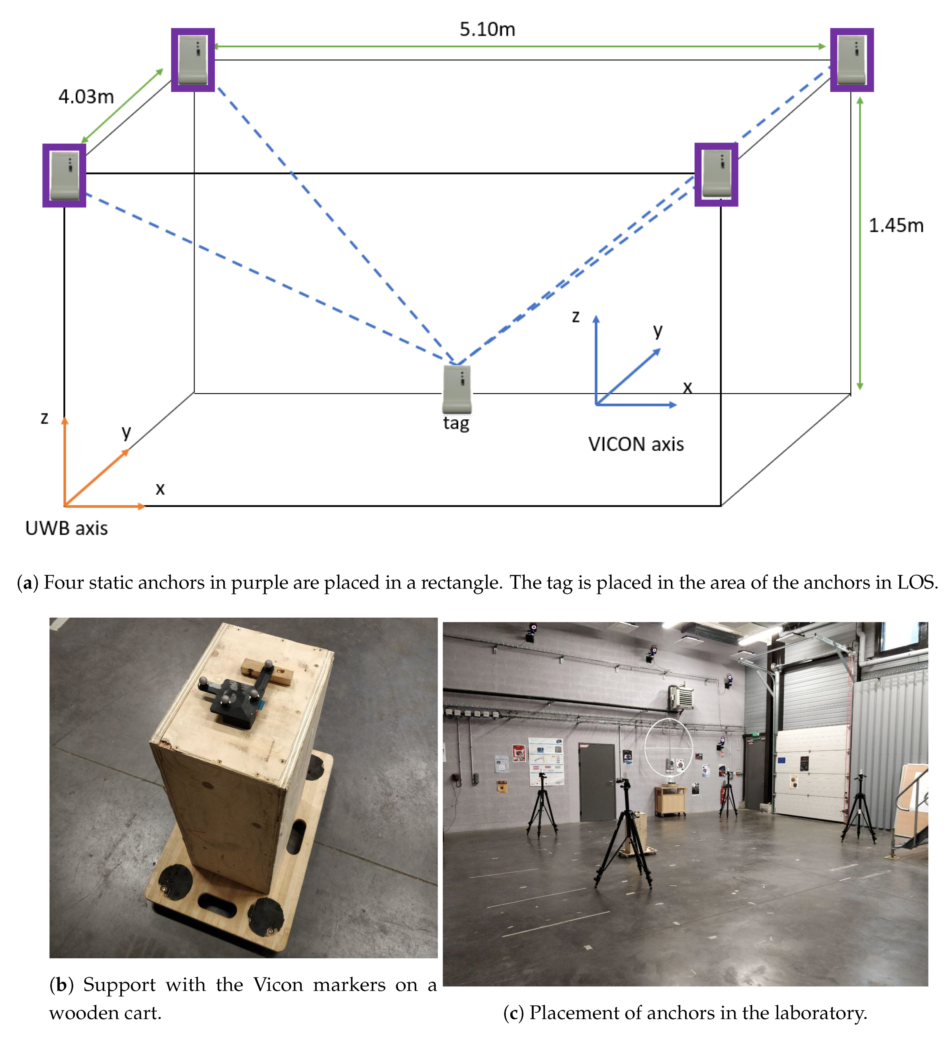
3.1. Experimental Setup

To evaluate the UWB systems, four anchors must first be placed in the room used for indoor localization. We align anchors with laser measurements. To be as accurate as possible, the anchors must be placed in a rectangle as described in [46]. Anchors are place respectively at (−2;5.03),(3.10;5.03),(−2;1),(3.10;1).
One anchor is chosen as reference (initialization at x = 0 and y = 0), and we must obtain the position of each anchor according to the initialization anchor as shown in Figure 1a.
We obtained the position of each anchors with a VICON motion capture system [47]. The area of testing in Figure 1a is in the lab with a LOS condition and in an industrial environment with a metallic structure, robots and a metallic door close to the testing area as shown in Figure 1c. The Tag is mounted on a support and placed on a wooden cart as illustrated in Figure 1b with a height of 0.7 m to verify the trajectory in 3D in the inner area of the UWB system. To limit interference, we placed the tag on a wooden cart pushed by a person far enough away from the tag. We expect 10 cm or 15 cm of accuracy with UWB technology in LOS conditions. We use the two-way ranging (TWR) standard algorithm embedded by Decawave.

3.2. Method of Comparison

We look how UWB behaves in a static condition and evaluate the precision and accuracy in a Line-of-Sight condition. We use the Vicon system as ground truth due to its ability to measure a position with a millimeter accuracy [47].
The Root Mean Square Error (RMSE) is computed as follows:
R M S E = 1 N i = 1 N ( θ i θ i ^ ) 2
and represents the average difference between the ground truth values from the Vicon system, written θ i , and the estimated value of the UWB system represented by θ i ^ . θ i ^ is the value of the i th point.
The empirical Cumulative Distribution Function of the error (eCDF) is computed as follow:
e C D F = F X ( x ) = x f X ( t ) d t .
Equation (2) allows seeing the distribution of values around the average, with f X ( t ) the integral of its probability density function.

3.3. Calibration

In this study, we have two datasets that contain the positions X,Y,Z, the Ultra WideBand sensor data and the VICON system data. Each dataset being in its own reference frame, we will therefore express the data of the Ultra WideBand system in the VICON reference frame. Before comparing the Ultra WideBand data with the VICON data, a rigid transformation between the two frames, named R V i c o n > U W B for the rotation and t V i c o n > U W B for the translation, is applied. First, we find the center of each point cloud given by the UWB and the Vicon system. The function is called Centroid and is defined by:
C e n t r o i d ( U w b ) = 1 N i N P i U W B
C e n t r o i d ( V i c o n ) = 1 N i N P i V i c o n
P i U W B and P i V i c o n are the position respectively of Ultra WideBand and VICON system. The aim of this step is to center the two datasets before establishing the rotation between the two frames. A covariance matrix, called H, is computed as follows:
H = i N ( P i U W B c e n t r o i d ( U w b ) ) ( P i V i c o n c e n t r o i d ( V i c o n ) ) T .
In a second step, we will use a SVD (Singular Value Decomposition) such that:
U , S , V = S V D ( H )
to find the rotation between the Vicon frame and the UWB frame [48,49] given by:
R V i c o n > U W B = V U T .
Sometimes, the SVD returns a reflection matrix that does not exist in a real situation. The solution is to multiply the third column of R (rotation) by −1 if the determinant of R is negative [49]. It then remains to find the translation between the two point clouds as below:
t U W B = C e n t r o i d ( V i c o n ) C e n t r o i d ( U w b ) .
This gives us the translation between the two point clouds:
P i U W B = R V i c o n > U W B × P i V i c o n + t V i c o n > U W B .

3.4. Tests and Evaluation

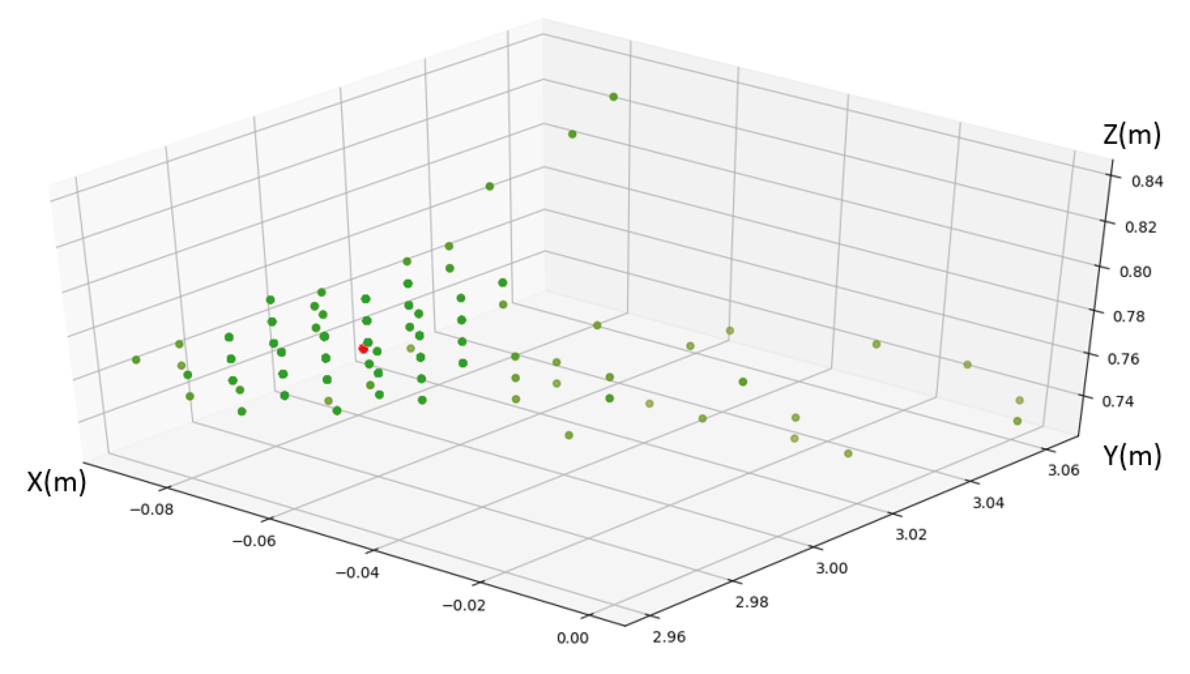
3.4.1. Static Measurement Precision

From a statistical point of view, the standard deviation corresponds to the precision, the mean error corresponds to the accuracy and the average range, the range of deviation [50]. The first test is to place the tag in the inner area of the UWB anchors. This test will give us the distribution of the UWB points when the tag is static.
The results of the static test are given in Table 3. The mean error on the 3 XYZ axes is 1 cm, and the average range, is 10 cm. The values are distributed around the average value with a standard deviation of 0.011 m. This means that the UWB system is not precise in a static situation, but has a high accuracy of 10 cm on average.
These results confirm those of Jimenez et al. [38,39] and results of Dotlic et al. [44] in static when using mean calculation. UWB is accurate up to 10 cm in static and behaves like a sphere around the target with a range value of 10 cm shown in Figure 2. When a person is not moving and the environment either, we know where the person is with the accuracy of 10 cm. We could use that information to improve dead reckoning during the static phase of it when an IMU (Inertial measurements Unit) is carried on the arm.

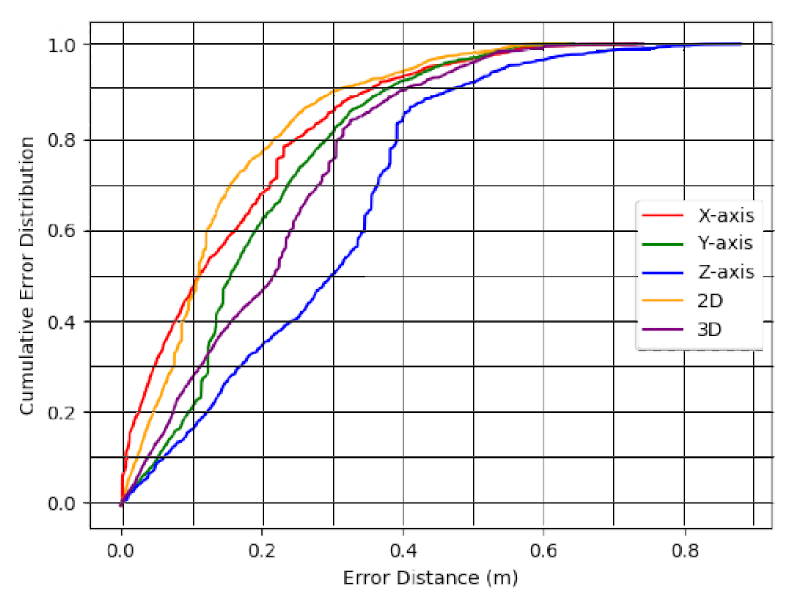
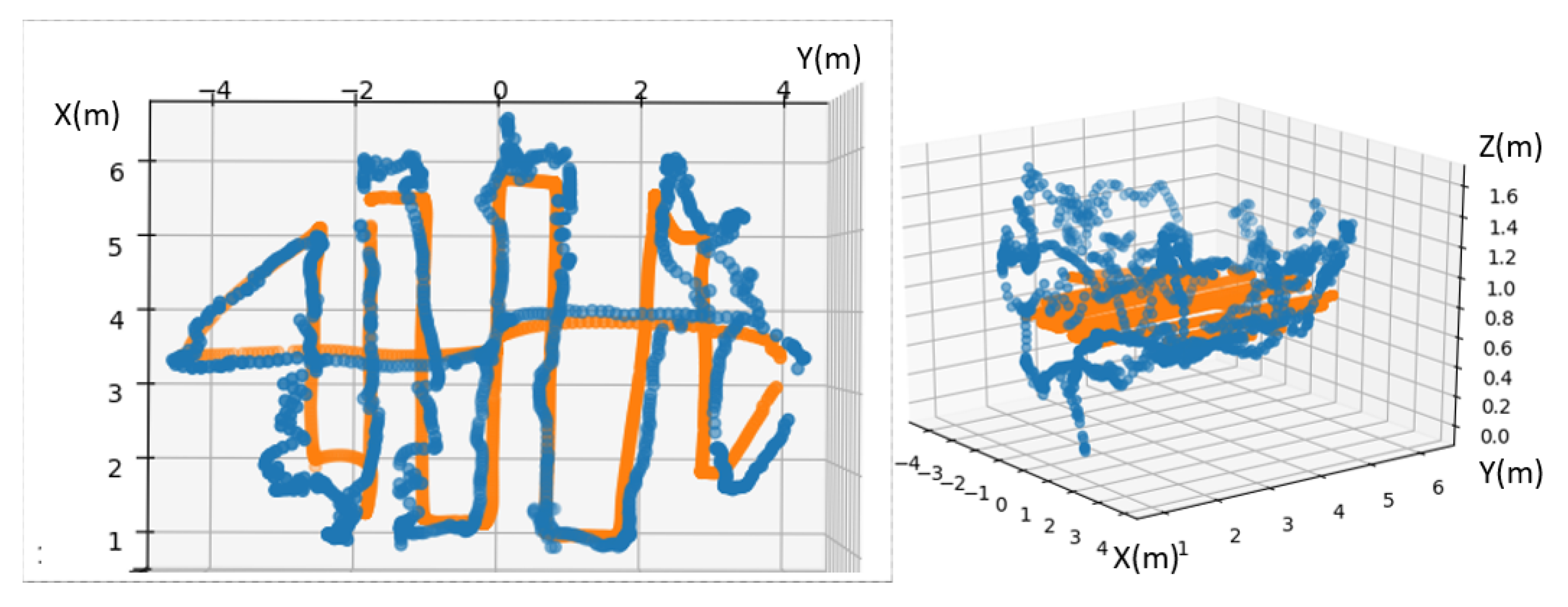
3.4.2. Dynamic Measurement Evaluation and Precision of a Trajectory

Thanks to the Vicon system [47], we compared the exact 3D point of the Vicon with the 3D point of UWB in real time using the RTMaps software (Real Time, Multisensor, Advanced Prototyping Software) (https://intempora.com/products/rtmaps.html) to log our data. The first test we made was a trajectory inside the inner area of the UWB anchors. The test was made in the laboratory in LOS with industrial conditions.
This result shows that, in dynamic localization, we can use UWB for motion tracking with X-Y axis in real time but not in 3D because the Z-axis is not trustable. Figure 3 highlights that the Z-axis measurements are wavy. Possible reasons of errors of Z-axis will be a vertical DOP because all anchors are at the same height.
In XY measurement, we have 21 cm of accuracy and 78% of values are better than 0.2 m as shown in Figure 4 and in Table 4. We have 0.135 m of standard deviation in XY for this trajectory in XY. We can use UWB for dynamic localization in real time. We have 0.24 m of accuracy in 3D (XYZ) only 40% of values for Z-axis are precise as shown in Figure 4. The Z-axis is not trustable for dynamic localization and for motion gesture recognition.

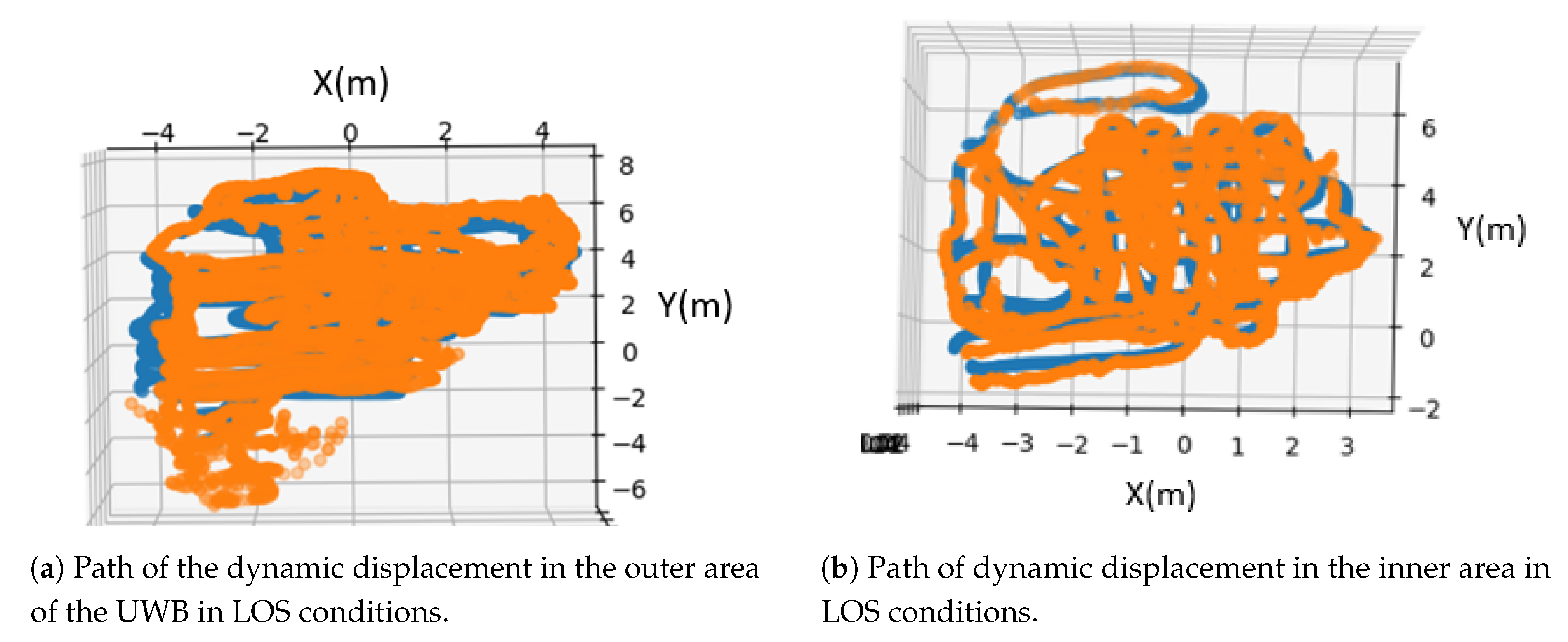
3.4.3. Dynamic Measurement Evaluation and Precision of Mapping

The third test is to realize a mapping of the outer area (Figure 5a) and inner area (Figure 5b) of the UWB system to evaluat its behaviour. We covered the maximum area and try to see if the accuracy/precision changed.
Mok et al. [51] describe all influential factors using Ultra WideBand for positioning such as material of obstruction, multipath, geometrical effect and signal attenuation. We know by this paper [51] that in our laboratory we have a metallic structure close to the testing area and metallic robots that can have influence on the data. Compared to our first test, we have the accuracy of 23 cm in the inner area and 25 cm in the outer area of 2D and 23 cm and 24 cm in 3D, this is close to our first result in dynamic localization shown in Table 4. These two tests show that UWB is homogeneous for a covered area even outside of the area defined by its anchors in industrial LOS conditions. UWB is really good for dynamic localization in indoor environments.
We lost the precision compared to our static results. We had 10 cm accuracy in static measurement, we had 0.24 m accuracy in dynamic localization as shown in Table 5. In the static case we have calculated a mean error while in the dynamic case we calculate an instantaneous error for each point. This is the main reason for the increase of the error in the dynamic case.

3.4.4. Test Z Anchor Change

This test was made to verify thebehaviour of the UWB system when the height of anchors changes. Ayan et al. [46] said that height of anchors can change the accuracy of UWB. In this test, we want to know the behaviour in a dynamic situation. We lowered 2 anchors 40 cm, and this change has been taken into consideration in the calibration measurements. We have a bad accuracy of 0.87 m in X–Y and 0.81 m in 3D as shown in Table 6 that confirms when Z anchors are not at the same height, accuracy and precision in dynamic localization are affected.

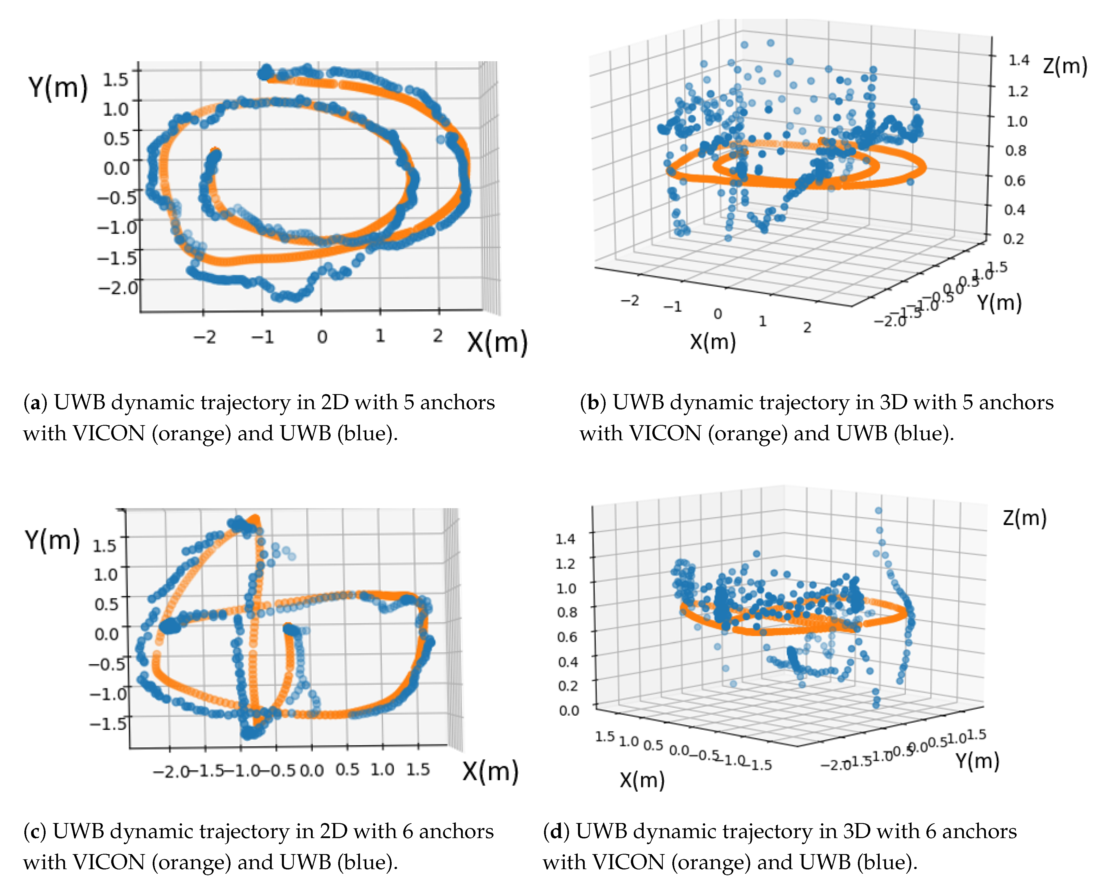
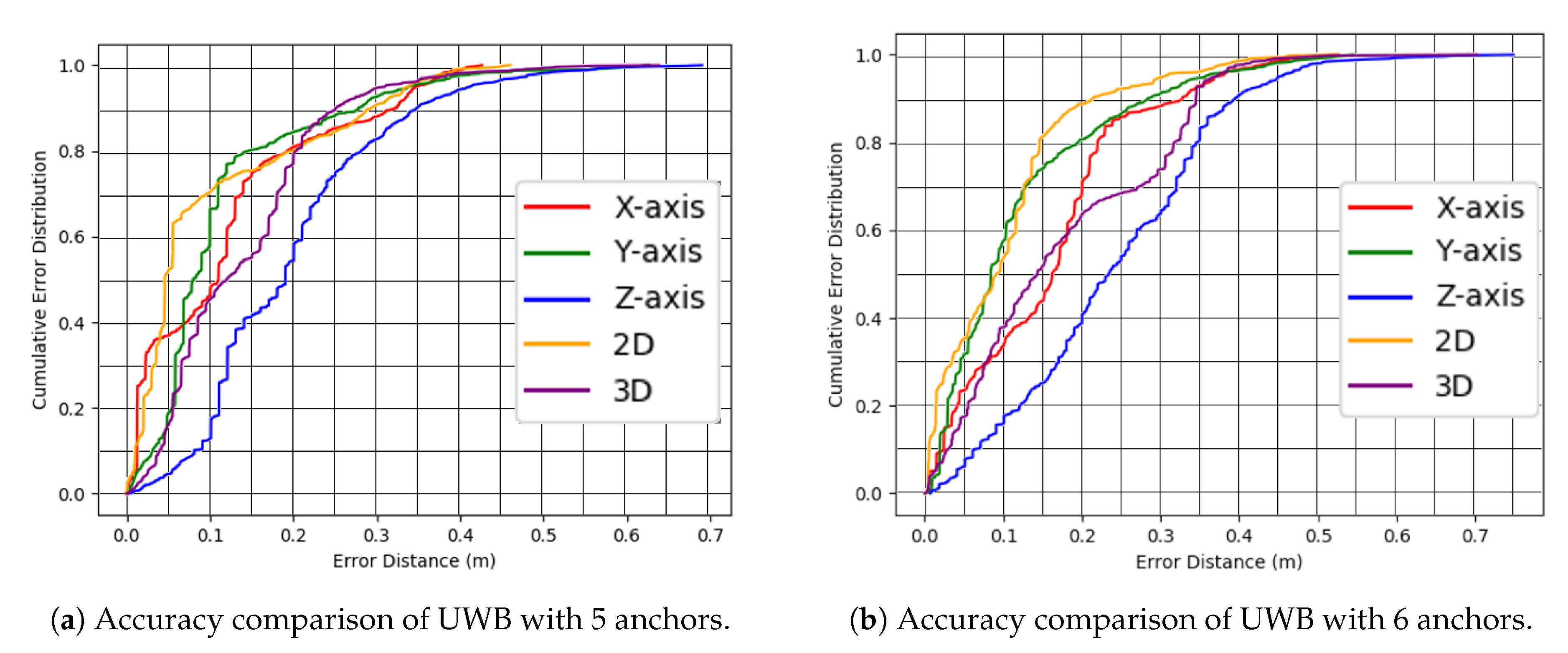
3.4.5. Study of the Influence of Anchors

This test was made to verify the behaviour of UWB in the inner area of UWB in dynamics with five and six anchors. We place four anchors exactly as in the Figure 1a and one more on the floor in one corner of our cube (five anchors configuration). And then we place four anchors as in the Figure 1 and two more on the floor in corners (six anchors configuration). The aim is to see a better performance of Z-axis. Having 5 or 6 anchors improves precision and accuracy for 3-axis, but Z-axis is still too wavy as shown in Figure 6b,d. The Z-axis has 0.22 m of mean error as shown in Table 7 that is better than 0.23 m shown in Table 5 but not significantly. Compared to the cumulative error distribution, we see an improvement of Z-axis about 10 cm, 80% of values are below 0.3 m as shown in Table 7 with five anchors and 80% of values are below 0.4 m accuracy with four anchors as shown in Figure 4. X axis has 80% of the values below 0.2 m as illustrated in Figure 7a that is better than our first dynamic test with four anchors shown in Figure 4. Y-axis also improves its precision. In Figure 7b that Z-axis has a bad precision 80% of values are above 0.3 m. We improve accuracy and precision of UWB by adding one or two anchor(s). According to the results of Table 7, for 5 anchors we have 5 cm in 2D and 6 cm in 3D. The performances are lower for 6 anchors. It is possible that the position of the sixth anchor leads to increase the influence of the undesired phenomenon that takes over to the advantage of using more anchors. One hypothesis could be that the signal received/transmitted from/to this sixth anchor has more multipath. However, something that is clearly visible in Figure 7 is the improvement of standard deviation. It means that the trajectory is less scattered, but remains centred in the same error in 2D.

4. Conclusions

In this article, we describe the behaviour of an Ultra WideBand system in static and dynamic cases by comparison with a ground truth obtained with a motion capture system. We have an evaluation of the precision and accuracy of the UWB system which is really good in the X-Y axes but not trustable along the Z-axis. We have also shown that if we change the height of the anchors, we lose accuracy and precision in static and dynamic localization. We also confirm that precision and accuracy are better by adding anchors when performing dynamic localization. UWB systems they can be a really good choice for localization, even in dynamic, and can be more robust if we add more anchors. Z-axis needs to be improved, mostly in terms of precision, and this can be achieved by data fusion with other sensors. Our future works will be the improvement of the accuracy and precision of the system by the addition of an IMU and a barometer and to see the feasibility of gesture recognition.

Author Contributions

Conceptualization, M.D.; Investigation, M.D.; Methodology, M.D., R.B. and X.S.; Supervision, R.B., X.S. and N.I.; Writing—original draft, M.D.; Writing—review and editing, R.B., X.S. and N.I. All authors have read and agreed to the published version of the manuscript.

Funding

This work was carried out as part of the LOCADYN research project, co-financed by the European Union. Europe commits itself in Normandy with the European Regional Development Fund (ERDF).

Conflicts of Interest

The authors declare no conflict of interest.

Abbreviations

The following abbreviations are used in this manuscript:
AoAAngle of Arrival
CEDCumulative Error Distribution
DOPDilution Of Precision
EKFExtended Kalman Filter
GNSSGlobal Navigation Satellite System
HMIHuman-Machine Interface
IMUInertial Measurement Unit
LOSLine-Of-Sight
MEMSMicro-Electro-Mechanical Systems
NLOSNon-Line-Of-Sight
RFIDRadio Frequency Identification
RMSERoot-Mean-Square Error
RSSIReceived Signal Strength Indicator
RTTRound-Trip Time
TDoATime Difference Of Arrival
ToATime of Arrival
UWBUltra WideBand

References

  1. Guna, J.; Jakus, G.; Pogačnik, M.; Tomažič, S.; Sodnik, J. An Analysis of the Precision and Reliability of the Leap Motion Sensor and Its Suitability for Static and Dynamic Tracking. Sensors 2014, 14, 3702–3720. [Google Scholar] [CrossRef] [PubMed] [Green Version]
  2. Tang, M. Recognizing Hand Gestures with Microsoft’s Kinect; Department of Electrical Engineering of Stanford University: Palo Alto, CA, USA, 2011. [Google Scholar]
  3. Junker, H.; Amft, O.; Lukowicz, P.; Tröster, G. Gesture spotting with body-worn inertial sensors to detect user activities. Pattern Recognit. 2008, 41, 2010–2024. [Google Scholar] [CrossRef]
  4. Fong, D.T.P.; Chan, Y.Y. The use of wearable inertial motion sensors in human lower limb biomechanics studies: A systematic review. Sensors 2010, 10, 11556–11565. [Google Scholar] [CrossRef] [PubMed] [Green Version]
  5. Dobkin, B.H. Wearable motion sensors to continuously measure real-world physical activities. Curr. Opin. Neurol. 2013, 26, 602–608. [Google Scholar] [CrossRef]
  6. Madgwick, S. An Efficient Orientation Filter for Inertial and Inertial/Magnetic Sensor Arrays. Rep. x-io Univ. Bristol (UK) 2010, 25, 113–118. [Google Scholar]
  7. Hamel, T.; Mahony, R. Attitude estimation on SO [3] based on direct inertial measurements. In Proceedings of the IEEE International Conference on Robotics and Automation (ICRA), Orlando, FL, USA, 15–19 May 2006; pp. 2170–2175. [Google Scholar]
  8. Combettes, C.; Renaudin, V. Delay Kalman filter to estimate the attitude of a mobile object with indoor magnetic field gradients. Micromachines 2016, 7, 79. [Google Scholar] [CrossRef] [PubMed] [Green Version]
  9. Michel, T.; Genevès, P.; Fourati, H.; Layaïda, N. On attitude estimation with smartphones. In Proceedings of the IEEE International Conference on Pervasive Computing and Communications (PerCom), Kona, HI, USA, 13–17 March 2017; pp. 267–275. [Google Scholar]
  10. Mautz, R. Indoor Positioning Technologies. Habilitation Thesis, ETH Zurich, Zürich, Switzerland, 2012. [Google Scholar]
  11. Zafari, F.; Gkelias, A.; Leung, K.K. A survey of indoor localization systems and technologies. IEEE Commun. Surv. Tutor. 2019, 21, 2568–2599. [Google Scholar] [CrossRef] [Green Version]
  12. Li, J.; Wang, C.; Kang, X.; Zhao, Q. Camera localization for augmented reality and indoor positioning: A vision-based 3D feature database approach. Int. J. Digit. Earth 2019, 1–15. [Google Scholar] [CrossRef]
  13. Kohoutek, T.K.; Mautz, R.; Donaubauer, A. Real-time indoor positioning using range imaging sensors. In Real-Time Image and Video Processing; International Society for Optics and Photonics: Bellingham, WA, USA, 2010. [Google Scholar]
  14. Niu, Q.; Li, M.; He, S.; Gao, C.; Gary Chan, S.H.; Luo, X. Resource-efficient and Automated Image-based Indoor Localization. ACM Trans. Sens. Networks (TOSN) 2019, 15, 19. [Google Scholar] [CrossRef]
  15. Ido, J.; Shimizu, Y.; Matsumoto, Y.; Ogasawara, T. Indoor Navigation for a Humanoid Robot Using a View Sequence. Int. J. Robot. Res. (IJRR) 2009, 28, 315–325. [Google Scholar] [CrossRef]
  16. Liao, X.; Chen, R.; Li, M.; Guo, B.; Niu, X.; Zhang, W. Design of a Smartphone Indoor Positioning Dynamic Ground Truth Reference System Using Robust Visual Encoded Targets. Sensors 2019, 19, 1261. [Google Scholar] [CrossRef] [PubMed] [Green Version]
  17. Tilch, S.; Mautz, R. Current investigations at the ETH Zurich in optical indoor positioning. In Proceedings of the IEEE Workshop on Positioning, Navigation and Communication, Dresden, Germany, 11–12 March 2010; pp. 174–178. [Google Scholar]
  18. Burki, B.; Guillaume, S.; Sorber, P.; Oesch, H.P. DAEDALUS: A versatile usable digital clip-on measuring system for Total Stations. In Proceedings of the IEEE International Conference on Indoor Positioning and Indoor Navigation (IPIN), Zurich, Switzerland, 15–17 September 2010; pp. 1–10. [Google Scholar]
  19. Khoshelham, K.; Elberink, S.O. Accuracy and Resolution of Kinect Depth Data for Indoor Mapping Applications. Sensors 2012, 12, 1437–1454. [Google Scholar] [CrossRef] [PubMed] [Green Version]
  20. Arai, T.; Yoshizawa, T.; Aoki, T.; Zempo, K.; Okada, Y. Evaluation of Indoor Positioning System based on Attachable Infrared Beacons in Metal Shelf Environment. In Proceedings of the IEEE International Conference on Consumer Electronics (ICCE), Las Vegas, NV, USA, 11–13 January 2019; pp. 1–4. [Google Scholar]
  21. Sato, T.; Nakamura, S.; Terabayashi, K.; Sugimoto, M.; Hashizume, H. Design and implementation of a robust and real-time ultrasonic motion-capture system. In Proceedings of the IEEE International Conference on Indoor Positioning and Indoor Navigation (IPIN), Guimaraes, Portugal, 21–23 September 2011; pp. 1–6. [Google Scholar]
  22. Wang, Y.T.; Li, J.; Zheng, R.; Zhao, D. ARABIS: An Asynchronous Acoustic Indoor Positioning System for Mobile Devices. In Proceedings of the IEEE International Conference on Indoor Positioning and Indoor Navigation (IPIN), Sapporo, Japan, 18–21 September 2017; pp. 1–8. [Google Scholar]
  23. Alarifi, A.; Al-Salman, A.; Alsaleh, M.; Alnafessah, A.; Al-Hadhrami, S.; Al-Ammar, M.A.; Al-Khalifa, H.S. Ultra wideband indoor positioning technologies: Analysis and recent advances. Sensors 2016, 16, 707. [Google Scholar] [CrossRef] [PubMed]
  24. Vasisht, D.; Kumar, S.; Katabi, D. Decimeter-level localization with a single WiFi access point. In Proceedings of the 13th USENIX Symposium on Networked Systems Design and Implementation (NSDI 16), Santa Clara, CA, USA, 16–18 March 2016; pp. 165–178. [Google Scholar]
  25. Xiong, J.; Jamieson, K. Arraytrack: A fine-grained indoor location system. In Proceedings of the 10th USENIX Symposium on Networked Systems Design and Implementation (NSDI 13), Lombard, IL, USA, 2–5 April 2013; pp. 71–84. [Google Scholar]
  26. Gansemer, S.; Grossmann, U.; Hakobyan, S. RSSI-based Euclidean Distance algorithm for indoor positioning adapted for the use in dynamically changing WLAN environments and multi-level buildings. In Proceedings of the IEEE International Conference on Indoor Positioning and Indoor Navigation (IPIN), Zurich, Switzerland, 15–17 September 2010; pp. 1–6. [Google Scholar]
  27. Cui, Y.; Zhang, Y.; Huang, Y.; Wang, Z.; Fu, H. Novel WiFi/MEMS Integrated Indoor Navigation System Based on Two-Stage EKF. Micromachines 2019, 10, 198. [Google Scholar] [CrossRef] [PubMed] [Green Version]
  28. Kiers, M.; Krajnc, E.; Dornhofer, M.; Bischof, W. Evaluation and Improvements of an RFID Based Indoor Navigation System for Visually Impaired and Blind People. In Proceedings of the IEEE International Conference on Indoor Positioning and Indoor Navigation (IPIN), Guimaraes, Portugal, 21–23 September 2011; p. 5. [Google Scholar]
  29. Shi, W.; Du, J.; Cao, X.; Yu, Y.; Cao, Y.; Yan, S.; Ni, C. IKULDAS: An Improved kNN-Based UHF RFID Indoor Localization Algorithm for Directional Radiation Scenario. Sensors 2019, 19, 968. [Google Scholar] [CrossRef] [PubMed] [Green Version]
  30. Patiño-Studencka, L.; Batzer, U.; Thielecke, J. Phase smoothing in a virtually synchronized pseudolite system using stochastic clock modelling. In Proceedings of the Ubiquitous Positioning Indoor Navigation and Location Based Service, Kirkkonummi, Finland, 14–15 October 2010; pp. 1–5. [Google Scholar]
  31. Fujii, K.; Sakamoto, Y.; Wang, W.; Arie, H.; Schmitz, A.; Sugano, S. Hyperbolic Positioning with Antenna Arrays and Multi-Channel Pseudolite for Indoor Localization. Sensors 2015, 15, 25157–25175. [Google Scholar] [CrossRef] [Green Version]
  32. Renaudin, V.; Merminod, B.; Kasser, M. Optimal data fusion for pedestrian navigation based on UWB and MEMS. In Proceedings of the IEEE/ION Position, Location and Navigation Symposium, Monterey, CA, USA, 5–8 May 2008; pp. 341–349. [Google Scholar]
  33. Susi, M.; Renaudin, V.; Lachapelle, G. Motion mode recognition and step detection algorithms for mobile phone users. Sensors 2013, 13, 1539–1562. [Google Scholar] [CrossRef]
  34. Blankenbach, J.; Norrdine, A. Position estimation using artificial generated magnetic fields. In Proceedings of the IEEE International Conference on Indoor Positioning and Indoor Navigation (IPIN), Zurich, Switzerland, 15–17 September 2010; pp. 1–5. [Google Scholar]
  35. Vandermeulen, D.; Vercauteren, C.; Weyn, M. Indoor localization Using a Magnetic Flux Density Map of a Building. In Proceedings of the International Conference on Ambient Computing, Applications, Services and Technologies, Porto, Portugal, 29 September–3 October 2013; pp. 42–49. [Google Scholar]
  36. Al-Hamad, A.; Ali, A.; Elhoushi, M.; Georgy, J. Indoor Navigation using Consumer Portable Devices in Cart/Stroller. In Proceedings of the International Technical Meeting of The Satellite Division of the Institute of Navigation (ION GNSS+ 2017), Portland, OR, USA, 25–29 September 2017; pp. 813–825. [Google Scholar]
  37. Dragomirescu, D.; Kraemer, M.; Jatlaoui, M.; Pons, P.; Aubert, H.; Thain, A.; Plana, R. 60GHz Wireless Nano-Sensors Network for Structure Health Monitoring as Enabler for Safer, Greener Aircrafts. In Advanced Topics in Optoelectronics, Microelectronics, and Nanotechnologies V; International Society for Optics and Photonics: Bellingham, WA, USA, 2010; Volume 7821. [Google Scholar]
  38. Ruiz, A.R.J.; Granja, F.S. Comparing Ubisense, BeSpoon, and DecaWave UWB location systems: Indoor performance analysis. IEEE Trans. Instrum. Meas. 2017, 66, 2106–2117. [Google Scholar] [CrossRef]
  39. Jiménez, A.R.; Seco, F. Comparing Decawave and Bespoon UWB location systems: Indoor/outdoor performance analysis. In Proceedings of the IEEE International Conference on Indoor Positioning and Indoor Navigation (IPIN), Alcala de Henares, Spain, 4–7 October 2016; pp. 1–8. [Google Scholar]
  40. Syberfeldt, A.; Ayani, M.; Holm, M.; Wang, L.; Lindgren-Brewster, R. Localizing operators in the smart factory: A review of existing techniques and systems. In Proceedings of the IEEE International Symposium on Flexible Automation (ISFA), Cleveland, OH, USA, 1–3 August 2016; pp. 179–185. [Google Scholar]
  41. Kulikov, R.S. Integrated UWB/IMU system for high rate indoor navigation with cm-level accuracy. In Proceedings of the Moscow Workshop on Electronic and Networking Technologies (MWENT), Moscow, Russia, 14–16 March 2018; pp. 1–4. [Google Scholar]
  42. Li, J.; Bi, Y.; Li, K.; Wang, K.; Lin, F.; Chen, B.M. Accurate 3D Localization for MAV Swarms by UWB and IMU Fusion. In Proceedings of the IEEE International Conference on Control and Automation (ICCA), Anchorage, AK, USA, 12–15 June 2018; pp. 100–105. [Google Scholar]
  43. Gharat, V.; Colin, E.; Baudoin, G.; Richard, D. Indoor performance analysis of LF-RFID based positioning system: Comparison with UHF-RFID and UWB. In Proceedings of the IEEE International Conference on Indoor Positioning and Indoor Navigation (IPIN), Sapporo, Japan, 18–21 September 2017; pp. 1–8. [Google Scholar]
  44. Dotlic, I.; Connell, A.; Ma, H.; Clancy, J.; McLaughlin, M. Angle of arrival estimation using decawave DW1000 integrated circuits. In Proceedings of the Workshop on Positioning, Navigation and Communications (WPNC), Bremen, Germany, 25–26 October 2017; pp. 1–6. [Google Scholar]
  45. Segura, M.; Hashemi, H.; Sisterna, C.; Mut, V. Experimental demonstration of self-localized ultra wideband indoor mobile robot navigation system. In Proceedings of the IEEE International Conference on Indoor Positioning and Indoor Navigation (IPIN), Zurich, Switzerland, 15–17 September 2010; pp. 1–9. [Google Scholar]
  46. Aryan, A. Evaluation of Ultra-Wideband Sensing Technology for Position Location in Indoor Construction Environments. Master’s Thesis, University of Waterloo, Waterloo, ON, Canada, 2011. [Google Scholar]
  47. Merriaux, P.; Dupuis, Y.; Boutteau, R.; Vasseur, P.; Savatier, X. A Study of Vicon System Positioning Performance. Sensors 2017, 17, 1591. [Google Scholar] [CrossRef]
  48. Eggert, D.; Lorusso, A.; Fisher, R. Estimating 3-D rigid body transformations: A comparison of four major algorithms. Mach. Vis. Appl. (MVA) 1997, 9, 272–290. [Google Scholar] [CrossRef]
  49. Besl, P.J.; McKay, N.D. Method for registration of 3-D shapes. In Sensor Fusion IV: Control Paradigms and Data Structures; International Society for Optics and Photonics: Bellingham, WA, USA, 1992; Volume 1611, pp. 586–606. [Google Scholar]
  50. Ku, H.H. Precision Measurement and Calibration. Volume 1. Statistical Concepts and Procedures; Technical Report; National Bureau of Standards: Gaithersburg, MD, USA, 1969.
  51. Mok, E.; Lau, F.; Xia, L.; Retscher, G.; Tian, H. Influential factors for decimetre level positioning using ultra wide band technology. Surv. Rev. 2012, 44, 37–44. [Google Scholar] [CrossRef]
Figure 1. Our UWB setup.
Sci 02 00023 g001
Figure 2. Distribution of the UWB points (in green) compared with the Vicon ground truth (in red).
Sci 02 00023 g002
Figure 3. Trajectory made in the laboratory with LOS conditions in 2D and 3D with VICON (orange) and UWB (blue) in meters.
Sci 02 00023 g003
Figure 4. Cumulative error distribution comparison between X-axis, Y-axis, Z-axis, 2D and 3D of UWB in a LOS industrial condition made in the laboratory.
Sci 02 00023 g004
Figure 5. Trajectory of the two dynamics displacements of UWB in orange and the Vicon in blue as the ground truth.
Sci 02 00023 g005
Figure 6. UWB dynamic trajectory made in the laboratory with 5 and 6 anchors with Vicon system as ground truth in industrial LOS conditions.
Sci 02 00023 g006
Figure 7. Empirical Cumulative Distribution Function of errors between X-axis, Y-axis, Z-axis, 2D and 3D of UWB in LOS industrial condition made in the laboratory.
Sci 02 00023 g007
Table 1. Indoor positioning technologies as described in [10].
TechnologyTypical AccuracyTypical CoverageTypical Measuring Principle
Cameras0.1 mm-dm1–10Codedmarkers
Infraredcm-m1–5 mIR camera
Tactile & Polar Systemsum-mm3–2000 mDistance & angular measurement
Soundcm2–10 mMultilateration
WLAN/WIFIm20–50 mFingerprinting
RFIDdm-m1–50 mCell of Origin
Ultra WideBandcm-m1–50 mToA, TDoA
High Sensitive GNSS10 m‘global’Assisted GNSS
Pseudolitescm-dm10–1000 mcarrierphaseranges
Other Radio Frequenciesm10–1000 mFingerprinting, cell of Origin, RSSI, RTT
Inertial Navigation1%10–100 mWLAN RSSI, GNSS
Magnetic Systemsmm-cm1–20 mDCfield, coils , AC magnetic field
Infrastructure Systemscm-mbuildingPowerlines, floor tiles, fluorescent lamps
Table 2. Comparison of Ultra WideBand (UWB) systems manufacturers.
UWB TechnologiesDecawave 1BlinkSight 2IIDRE 3BeSpoon 4
AccuracyX-Y 10 cm10 cm10–30 cm10 cm
Detecting Range290 m200+ m150 m600 m
Bandwith3.5–6.5 GHz7–8.5 GHz3.5–6.5 GHz3.5–4.5 GHz
Current Consumption30 mA30 mAMax 30 mA30 mA
InterfaceSpi controlwifiBluetooth USB RS232USB
Cost (euros)300 (kit)N/A1140650
Table 3. Comparison of mean localization errors and standard deviation with a static test in Line-Of-Sight condition.
Static LOS TestX-AxisY-AxisZ-Axis2D3D
Mean error0.01 m0.01 m0.01 m0.01 m0.01 m
Range0.09 m0.10 m0.11 m0.09 m0.10 m
Standard deviation0.01 m0.01 m0.01 m0.01 m0.01 m
Table 4. Table of dynamic trajectory.
Dynamic MeasureX-AxisY-AxisZ-Axis2D3D
Mean error0.20 m0.22 m0.32 m0.21 m0.24 m
Range0.73 m0.64 m0.87 m0.65 m0.75 m
Standard deviation0.13 m0.14 m0.29 m0.13 m0.18 m
Table 5. Errors of the dynamic measurement of the mapping.
UWB MappingX-AxisY-AxisZ-Axis2D3D
InnerMean error0.30 m0.17 m0.23 m0.23 m0.23 m
Range1.07 m0.60 m1.37 m0.56 m1.01 m
Standard deviation0.18 m0.00 m0.20 m0.18 m0.12 m
OuterMean error0.23 m0.27 m0.23 m0.25 m0.24 m
Range0.98 m1.05 m1.03 m1.01 m1.02 m
Standard deviation0.03 m0.15 m0.19 m0.09 m0.12 m
Table 6. Dynamic result with different heights for anchors.
Anchors Z ChangeX-AxisY-AxisZ-AxisMeasure 2DMeasure 3D
Mean error0.38 m1.37 m0.70 m0.87 m0.81 m
Range0.78 m0.64 m1.28 m0.71 m0.90 m
Standard deviation0.04 m0.05 m0.22 m0.04 m0.10 m
Table 7. Influence of UWB anchors in LOS conditions in industrial environment.
Influence
of Anchors
X-AxisY-AxisZ-Axis2D3D
4 anchorsMean error0.20 m0.22 m0.32 m0.21 m0.24 m
Range0.73 m0.64 m0.87 m0.65 m0.75 m
Standard
deviation
0.13 m0.14 m0.29 m0.13 m0.18 m
5 anchorsMean error0.16 m0.16 m0.22 m0.16 m0.18 m
Range0.42 m0.60 m0.66 m0.51 m0.56 m
Standard
deviation
0.02 m0.10 m0.22 m0.06 m0.11 m
6 anchorsMean error0.19 m0.16 m0.27 m0.17 m0.20 m
Range0.52 m0.54 m0.74 m0.53 m0.6 m
Standard
deviation
0.10 m0.01 m0.26 m0.05 m0.12 m

