Abstract
High diffraction signal-to-background ratios (SBRs), the ratio of diffraction peak integrated intensity over its background intensity, are desirable for a neutron diffractometer to acquire good statistics for diffraction pattern measurements and subsequent data analysis. For a given detector, while the diffraction peak signals primarily depend on the characteristics of the neutron beam and sample coherent scattering, the background largely originates from the sample incoherent scattering and the scattering from the instrument space. In this work, we investigated the effect of collimation on neutron diffraction SBRs of Si powder measurements using one high-angle area detector bank coupled with six different collimation configurations in a large and complex instrument space at the engineering materials diffractometer VULCAN, SNS, ORNL. The results revealed that the diffraction SBRs can be significantly improved by a proper coarse collimator that leaves no gap between the detector and the collimator, and the improvement of SBRs by a fine radial collimator was remarkable with a proper coarse collimator in place but not distinguishable without one. It was also found that the diffraction SBRs were not effectively improved by adding the neutron-absorbing element boron to the fine radial collimator body, which indicates that either the absorption of secondary scattered neutrons by the added boron is insignificant or the collimator base material (resin and ABS) alone attenuates background scattering sufficiently. These findings could serve as a useful reference for diffractometer developers and/or operators to optimize their collimation to achieve higher diffraction SBRs.
1. Introduction
Neutron diffraction is a powerful tool for probing the microstructures of materials and their response to external stimuli on an atomic level but in a bulk statistics fashion. High signal-to-background ratios (SBRs), i.e., the ratio of diffraction peak integrated intensity over its background intensity, are desirable for a neutron diffractometer to acquire sufficient statistics for diffraction pattern measurements and subsequent data analysis. For a given neutron detector, while the diffraction signal primarily depends on the neutron beam characteristics (flux, wavelengths, etc.) and the sample coherent scattering characteristics (coherent scattering length, structure factor, etc.), the background largely originates from the sample incoherent scattering and the scattering from the instrument space. The operation of a neutron diffractometer can involve a relatively large and open instrument space with varied sample environments, such as furnaces, cryostats, load frames [1], and other complex devices, e.g., a friction stirring welding system [2] or an additive manufacturing system [3]. Everything in the instrument space, including air, infrastructure hardware, and sample environment devices, can interact with neutrons either from the direct incident neutron beam or secondary scattering and cause a noticeable scattering background. While efforts are made to avoid or reduce materials other than the sample on the direct neutron beam path, collimation is another efficient way to reduce the detection of background scattering.
The general principle of collimation for neutron diffraction is to let an area detector only “see” the scattered neutrons from a sample or a specific region of interest within a sample. A radial collimation system is typically used for neutron diffractometers, as shown by the schematic in Figure 1. The coarse collimator is a shell box with a neutron absorbing liner (e.g., cadmium sheet, borated polymer) on the inside surfaces, while the fine collimator has dense fin or blade inserts made of neutron absorption materials (e.g., Gd2O3 coated Mylar foils or steel sheet [4], B4C coated Kapton foils [5], Zr-Gd foils [6]). In such a way, the collimators provide a focal point for scattered neutrons from the sample and reduce background scattering arriving at the detector from the instrument space such as the air and sample environment. It should be noted that the fine collimator fins can act as another source of secondary scattering depending on their material composition. Hydrogen materials, such as Mylar and thermoplastics, are of typical concern for their strong incoherent scattering [7,8] but are also demonstrated to attenuate neutrons through scattering and then absorbing when borated or coated with Gd paint [9].
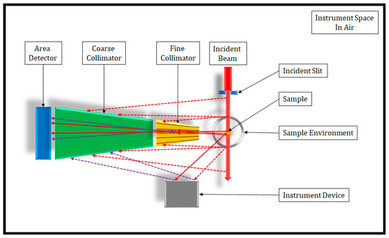
Figure 1.
Top-view schematic of collimation for an area detector when a cylinder sample is illuminated by neutron beam. The sample environment and instrument device are shown as examples of sources of direct and secondary scattering other than the sample in the instrument space. A few schematic neutron flight paths are shown by red solid lines for direct scattering from the sample, red dash lines for direct scattering from materials other than the sample, and purple dash lines for secondary scattering from the general instrument space.
While there are a few documented studies on the performance of radial collimators for neutron scattering, those studies were mainly focused on the field of view that is critical to define the sample gauge volume [6,10,11] or necessary to block scattering from the sample environment close to the sample [4,5,12,13,14]. Some notes were marked on improved SBRs for vanadium measurements and reduced secondary scattering for diamond powder measurements by collimators [9]. However, to our best knowledge, there are no data publicly available that assess the effect of collimation in a large open instrument space on the diffraction peak-to-background SBRs. In this work, we report the diffraction SBRs of Si powder measurements using one high-angle 3He position-sensitive area detector bank coupled with several different collimation configurations at the engineering materials diffractometer VULCAN [15,16] at the Spallation Neutron Source (SNS), Oak Ridge National Laboratory (ORNL). Based on the results, we briefly discussed the role of coarse collimator, fine collimator, and collimator materials in their effect on the diffraction SBRs.
2. Materials and Methods
2.1. Experiment Setup
The experiment was carried out at VULCAN, SNS, ORNL. VULCAN is a time-of-flight (TOF) diffractometer now equipped with six area detector banks. One high-angle 3He position-sensitive area detector bank was used to measure a Si powder sample loaded in a vanadium cylinder can (6 mm outer diameter). The high-angle detector was chosen mainly because it was equipped with two sets of 3D-printed plastic fine collimators, and it was cost effective to 3D print a counter borated part for comparison. Another advantage of using a high-angle detector is that the diffraction peak signal is intrinsically relatively low due to the low structure factor at high angles (from high order peaks), and the SBRs are expected to be more affected, given relatively uniform background scattering.
Six different collimation configurations were tested in two groups, as listed in Table 1. Schematics and selected photos of those configurations are shown in Figure 2. The details are specified in the following.

Table 1.
Collimation configurations for the Si powder measurements.
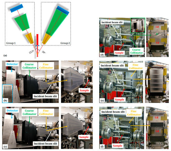
Figure 2.
Experiment set-up with different collimation configurations at VULCAN: (a) schematic top view of Group 1 and 2 configurations; (b) Config. 1-2, (c) Config. 1-3, (d) Config. 2-1, (e) Config. 2-2, and (f) Config. 2-3. The left-bottom insert in (b) shows the front view of the detector. The right-top insert in (d) shows the side view of the aluminum coarse collimator. Both insert views were not taken during the experiment but for illustration here only.
In Group 1, one 3D-printed coarse collimator and two sets of 3D-printed fine collimators were tested.
- A shell box made of acrylonitrile butadiene styrene (ABS) thermoplastic was used as the coarse collimator, as shown in Figure 2b,c. The box was fabricated by 3D printing but not based on a specific design that well fits to this high-angle detector. The large gaps between the detector, coarse collimator, and fine collimator still leave the chance for the detector bank to “see” quite a large amount of secondary scattering from the instrument space. The box was not lined with neutron absorbing material on its inside surface but was proved to be effective in blocking some secondary scattering when it was originally used at the fine collimator position for an area detector at 2θ = 90°.
- The fine collimators were made of Accura 60 Resin by 3D printing. As shown in Figure 2b,c, the fine collimators are composed of a number of thin (0.75–1.5 mm) vertical fins, which define a specified horizontal field of view (FOV) at the sample position (about 2 m from the detector plane). Four relatively thick (2 mm) horizontal frames were designed to reinforce the thin fin structure and prevent the fins from buckling or collapsing. While the two fine collimators in Config. 1-2 and Config. 1-3 share the same dimensions in footprint, the 20 mm FOV collimator has 50% fewer but 50% thicker fins than the 10 mm one. This means that the 20 mm FOV collimator has the same cross section area for neutrons to pass through but a 50% smaller inner surface area in comparison to the 10 mm one.
In Group 2, one conventional coarse collimator and two sets of 3D-printed fine collimators were tested.
- The coarse collimator was made of an aluminum sheet and lined with a cadmium sheet on the inner surface. It is a good fit to cover the gaps between the detector and the fine collimator. The front of the coarse collimator was blocked by two cadmium sheets so to have the middle 1/5 area open. This opening range was applied for all three configurations in this group, which matched the fine collimator design for Config. 2-3 and thus ensured the controlled comparison between the three configurations.
- A prototype fine collimator made of boron carbide infused ABS (45% by weight) by 3D printing was used in Config. 2-3, which matched the middle part of the 10 mm FOV resin fine collimator used in Config. 2-2. A special mount was printed to sit the ABS collimator at the same position as the middle part of the resin collimator.
It is worth noting that there are two additional variables when Group 1 configurations are compared to Group 2. One is that the detector was placed at nearly mirrored locations with respect to the incident beam, having a slight angle difference, as shown in Figure 2a. Specifically, the detector in Group 2 was on the left side of incident beam when looking downstream, and the detector plane normal was 30° off the incident beam direction; the same detector in Group 2 was relocated on the right side for Group 1 measurements, and that angle was 23.5°. The instrument had used different sample environments during the Si powder measurements. There was a mechanical load frame sitting on the sample stage in Group 2, while an additive manufacture (AM) system was at the instrument in Group 1. The sample environment devices were not on the path of the direct neutron beam in both cases. Those differences may affect the secondary scatterings in the instrument space that contribute to the background scattering, but they do not necessarily impact the conclusion to be drawn from the experiment.
2.2. Powder Measurements and SBRs
The TOF diffractometer utilizes neutrons that have a wide range of wavelengths that can be tuned by adjusting the chopper settings. A Si powder was measured for 5 min at 30 Hz chopper setting for Group 1 configurations and for 1 h at 20 Hz for Group 2 configurations. The SNS power was at nominal 1.4 MW for all the measurements. The incident slit opening was 5 mm by 12 mm. Note that, given the same beam power and incident slit opening, the 20 Hz chopper frequency setting would cut the beam pulses to the sample by 33% compared to the 30 Hz setting but allow for a wider coverage of d spacing.
The diffraction SBR is defined as the ratio of diffraction peak intensity over its background intensity by the following equation:
The peak intensity and corresponding background intensity were determined by single peak fit using VDRIVE [17] coupled with GSAS [18], as illustrated in Figure 3. is defined as the integral intensity over the peak width with the peak cutoff value of 0.05%, while is defined as the intensity of background at the peak center position. The initial input of lattice information for the single peak fit was obtained from the ICSD database.
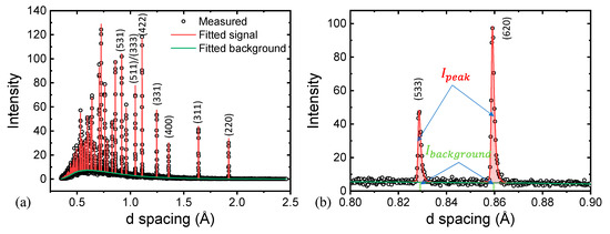
Figure 3.
An example of (a) Si powder diffraction pattern refinement with GSAS and (b) determination of peak and background intensity over individual peaks.
The SBRs are expected to exhibit variations along lattice d spacings in the diffraction measurement, as the high-d part is mostly contributed by the neutrons of long wavelengths and the low-d part by those of short wavelengths, and wavelength is one of the important factors that determine the scattering behavior of neutrons when they interact with materials. A total of 25 peaks in the d space range of 0.5–2 Å were fitted for SBRs determination with Group 2 configurations, and a total of 24 peaks with Group 1 configurations. The one peak missing from Group 1 was (220) at 1.920 Å, which was due to the narrower d spacing coverage associated with the 30 Hz chopper frequency setting.
3. Results
The detector views of the Si powder measurements under six collimation configurations are shown in Figure 4. Without any fine collimator, the detector view in Figure 4a shows a relatively uniform distribution of the scattered neutron counts across the entire detector area. The contrast of the vertical fringes is caused by the double-row design of the detector bank, in which the back-row stainless steel detector tubes are fractionally shadowed by the front-row tubes and show lower intensity. This alternative contrast change is expected and not related to the collimator performance. When a fine collimator is in place (Figure 4b,c), some dark ribbons show up. They are associated with the horizontal support frames and vertical fins in the fine collimator that slow down and scatter away some neutrons. The 20 mm FOV fine collimator seems to cause more neutron loss as it has relatively thicker fins. Both fine collimators seem to attenuate more neutrons on the right side, which is likely due to their non-perfect alignment in the transverse direction. These results indicate that the collimator made of resin can attenuate neutrons effectively.
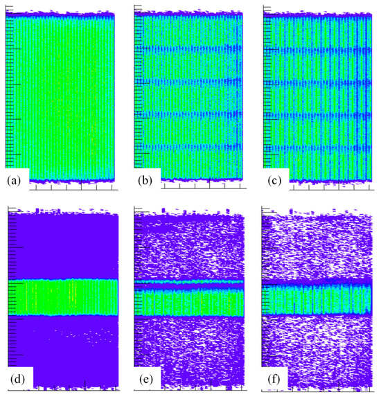
Figure 4.
The 2D detector views of Si powder measurements under six collimation configurations: (a) Config. 1-1, (b) Config. 1-2, (c) Config. 1-3, (d) Config. 2-1, (e) Config. 2-2, and (f) Config. 2-3. Lighter colors (e.g., green, yellow) indicate higher intensity of detected neutrons, while darker colors (e.g., blue, purple) indicate lower intensity.
With Cd sheets covering 4/5 of the front of coarse collimator, a clean edge is seen of the middle 1/5 illuminated section in Figure 4d, which demonstrates the excellent neutron shielding performance of cadmium. The intensity of scattered neutrons dropped when fine collimators were in place, as shown in Figure 4e,f. There was a minor vertical misalignment of the resin collimator that has one horizontal support frame in the way of the neutron path to the detector middle upper section. Also note that the vertical fins of the ABS collimator seem to be blocking more neutrons, which should be a result of minor misalignment in the radial direction, as the intensity seems weakened relatively uniformly across the entire region instead of only in the fins region. The misalignments are largely due to the non-rigid temporary mount support. Both minor misalignments should not affect the collected neutron data in terms of SBR, as the misalignment attenuates both direct and secondary scattered neutrons simultaneously. But it indeed demonstrated that the fine collimator alignment is critical for the transmission efficiency.
Figure 5 shows the obtained SBRs as a function of d spacing for all six configurations. The SBR increases with d spacing as a result of three fundamental mechanisms: the first is that the scattering structure factor is larger for higher d spacing peaks [19], which yields a stronger diffraction peak signal; the second is that longer wavelength neutrons that contribute to higher d spacing scattering tend to be absorbed more easily [20], which leads to a lower background scattering; the third is that the neutron beam flux at SNS, more specifically at VULCAN, has a lower intensity of neutrons of longer wavelengths, which corresponds to a reduced total number of neutrons for higher d spacing scattering [21].
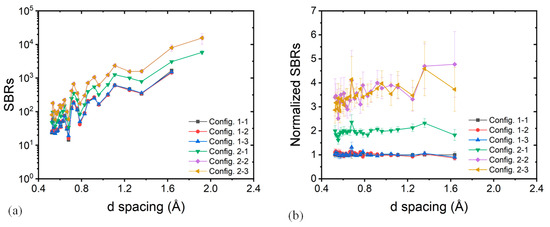
Figure 5.
SBRs as a function of d spacing from Si powder measurements under six collimation configurations: (a) SBRs as calculated and (b) SBRs normalized by that of Config. 1-1 values.
4. Discussion
On a holistic level, Group 1 configurations (with the non-well-fitted plastic coarse collimator) show similar lowest SBRs, while Group 2 configurations (with the well-fitted Cd-inner-lined aluminum coarse collimator) show higher SBRs. The normalized SBRs in Figure 5b show a factor of two improvement from Config. 1-1 to Config. 2-1. Moreover, adding fine collimators to Config. 1-1, as in Config. 1-2 and 1-3, hardly improves the SBRs. These results indicate that the secondary scattered neutrons attenuated by the coarse collimator account for a large part of the background scattering even though they are not from the scattering direction. Without a proper coarse collimator, a fine radial collimator can hardly improve the SBRs in a large and complex instrument space.
By adding a fine collimator to the well-fitted Cd-lined coarse collimator, the SBRs are improved significantly by another factor of 1.5–2.5 from Config. 2-1 to Config. 2-2 and 2-3. It is interesting to note that there is no evident difference between the SBRs under Config. 2-2 with the resin fine collimator and Config. 2-3 with the boron carbide infused ABS fine collimator. These results indicate that both resin and ABS fine collimators can effectively attenuate additional background scattering with a proper coarse collimator in place. The boron addition seems not to improve the SBRs as expected for the neutron diffractometer in this study. Possible reasons for this “underperformance” could be either that the absorption of secondary scattered neutrons by the added boron is insignificant or that the collimator base material (resin and ABS) alone attenuates background scattering sufficiently.
5. Conclusions
In this work, the effect of collimation on the neutron diffraction SBRs (the ratio of diffraction peak integrated intensity over its background intensity) of Si powder measurements was investigated using one high-angle 3He position-sensitive area detector bank coupled with six different collimation configurations in a large and complex instrument space at VULCAN, SNS, ORNL. The results revealed that a proper coarse collimator attenuated the background scattering and improved the SBRs significantly, and the improvement of SBRs by a fine radial collimator was remarkable with a proper coarse collimator in place. Without a proper coarse collimator, a fine radial collimator hardly improved the SBRs. It was also found that adding the neutron absorbing element boron to the fine radial collimator body did not effectively improve the diffraction SBRs, which indicates that either the absorption of secondary scattered neutrons by the added boron is insignificant or the collimator base material (resin and ABS) alone attenuates background scattering sufficiently. These findings could serve as a useful reference for diffractometer developers and/or operators to optimize their collimation to achieve higher SBRs.
Author Contributions
Conceptualization, D.Y., Y.C. and K.A.; methodology, D.Y.; software, K.A.; validation, Y.C.; formal analysis, D.Y.; investigation, D.Y.; resources, D.C., K.B., H.S. and K.A.; data curation, D.Y.; writing—original draft preparation, D.Y.; writing—review and editing, Y.C., D.C., K.B., H.S. and K.A.; visualization, D.Y.; supervision, K.A.; project administration, D.Y.; funding acquisition, K.A. All authors have read and agreed to the published version of the manuscript.
Funding
This research received no external funding.
Data Availability Statement
The data presented in this study are available on request from the corresponding author.
Acknowledgments
The neutron diffraction experiments were carried out at the Spallation Neutron Source (SNS), which is the U.S. Department of Energy (DOE) user facility at the Oak Ridge National Laboratory, sponsored by the Scientific User Facilities Division, Office of Basic Energy Sciences.
Conflicts of Interest
The authors declare no conflicts of interest.
References
- Hewat, A.; Bailey, I. D1a, a High Resolution Neutron Powder Diffractometer with a Bank of Mylar Collimators. Nucl. Instrum. Methods 1976, 137, 463–471. [Google Scholar] [CrossRef]
- Li, Y.; Hou, P.; Kamath, R.R.; Feng, Z.; An, K.; Choo, H. Real-Time Evolution of Texture and Temperature During Friction Stir Processing of a Magnesium Alloy: An Operando Neutron Diffraction Study. Acta Mater. 2024, 270, 119842. [Google Scholar] [CrossRef]
- Plotkowski, A.; Saleeby, K.; Fancher, C.M.; Haley, J.; Madireddy, G.; An, K.; Kannan, R.; Feldhausen, T.; Lee, Y.; Yu, D.; et al. Operando Neutron Diffraction Reveals Mechanisms for Controlled Strain Evolution in 3D Printing. Nat. Commun. 2023, 14, 4950. [Google Scholar] [CrossRef] [PubMed]
- Wright, A.F.; Berneron, M.; Heathman, S.P. Radial Collimator System for Reducing Background Noise During Neutron Diffraction with Area Detectors. Nucl. Instrum. Methods 1981, 180, 655–658. [Google Scholar] [CrossRef]
- Stone, M.B.; Niedziela, J.L.; Loguillo, M.J.; Overbay, M.A.; Abernathy, D.L. A Radial Collimator for a Time-of-Flight Neutron Spectrometer. Rev. Sci. Instrum. 2014, 85, 085101. [Google Scholar] [CrossRef] [PubMed]
- Qiu, J.; Hu, C.; Liu, Y.; Zhou, L.; Shen, F.; Jin, D.; Du, W.; Ding, C.; Song, W.; Huang, Y.; et al. Neutron Radial Collimator Using Zr–Gd Alloy Foil as Collimating Blade for Engineering Material Diffractometer. Nucl. Instrum. Methods Phys. Res. Sect. A Accel. Spectrometers Detect. Assoc. Equip. 2022, 1033, 166684. [Google Scholar] [CrossRef]
- Stone, M.B.; Siddel, D.H.; Elliott, A.M.; Anderson, D.; Abernathy, D.L. Characterization of Plastic and Boron Carbide Additive Manufactured Neutron Collimators. Rev. Sci. Instrum. 2017, 88, 123102. [Google Scholar] [CrossRef] [PubMed]
- Nakamura, M.; Kambara, W.; Iida, K.; Kajimoto, R.; Kamazawa, K.; Ikeuchi, K.; Ishikado, M.; Aoyama, K. Performances of Oscillating Radial Collimator for the Fermi Chopper Spectrometer 4seasons at J-Parc. Phys. B Condens. Matter 2018, 551, 480–483. [Google Scholar] [CrossRef]
- Tamalonis, A.; Weber, J.K.R.; Neuefeind, J.C.; Carruth, J.; Skinner, L.B.; Alderman, O.L.G.; Benmore, C.J. Note: Detector Collimators for the Nanoscale Ordered Materials Diffractometer Instrument at the Spallation Neutron Source. Rev. Sci. Instrum. 2015, 86, 096105. [Google Scholar] [CrossRef] [PubMed]
- Withers, P.; Johnson, M.; Wright, J. Neutron Strain Scanning Using a Radially Collimated Diffracted Beam. Phys. B Condens. Matter 2000, 292, 273–285. [Google Scholar] [CrossRef]
- Torii, S.; Moriai, A. The Design of the Radial Collimator for Residual Stress Analysis Diffractometer of J-Parc. Physica B Condensed Matter 2006, 385–386, 1287–1289. [Google Scholar] [CrossRef]
- Ridley, C.J.; Manuel, P.; Khalyavin, D.; Kirichek, O.; Kamenev, K.V. A Novel Compact Three-Dimensional Laser-Sintered Collimator for Neutron Scattering. Rev. Sci. Instrum. 2015, 86, 095114. [Google Scholar] [CrossRef] [PubMed]
- Haberl, B.; Molaison, J.J.; Frontzek, M.; Novak, E.C.; Granroth, G.E.; Goldsby, D.; Anderson, D.C.; Elliott, A.M. 3D-Printed B4c Collimation for Neutron Pressure Cells. Rev. Sci. Instrum. 2021, 92, 093903. [Google Scholar] [CrossRef] [PubMed]
- Tsunoda, M.; Honda, T.; Ikeda, K.; Ohshita, H.; Kambara, W.; Otomo, T. Radial Collimator Performance and Future Collimator Updates for the High-Intensity Total Scattering Diffractometer Nova at J-Parc. Nucl. Instrum. Methods Phys. Res. Sect. A Accel. Spectrometers Detect. Assoc. Equip. 2023, 1055, 168484. [Google Scholar] [CrossRef]
- An, K.; Skorpenske, H.D.; Stoica, A.D.; Ma, D.; Wang, X.-L.; Cakmak, E. First in Situ Lattice Strains Measurements under Load at Vulcan. Metall. Mater. Trans. A 2011, 42, 95–99. [Google Scholar] [CrossRef]
- An, K.; Chen, Y.; Stoica, A.D. Vulcan: A “Hammer” for High-Temperature Materials Research. MRS Bull. 2019, 44, 878–883. [Google Scholar] [CrossRef]
- An, K. Data Reduction and Interactive Visualization Software for Event Mode Neutron Diffraction; ORNL Report; Oak Ridge National Laboratory: Oak Ridge, TN, USA, 2012; p. 621.
- Larson, A.C.; Von Dreele, R.B. General Structure Analysis System; Report LAUR; Los Alamos National Laboratory: Los Alamos, NM, USA, 2004; pp. 86–748.
- Hutchings, M.T.; Withers, P.J.; Holden, T.M.; Lorentzen, T. Introduction to the Characterization of Residual Stress by Neutron Diffraction; CRC Press: Boca Raton, FL, USA, 2005. [Google Scholar]
- Rennie, A.R.; Engberg, A.; Eriksson, O.; Dalgliesh, R.M. Understanding Neutron Absorption and Scattering in a Polymer Composite Material. Nucl. Instrum. Methods Phys. Res. Sect. A: Accel. Spectrometers Detect. Assoc. Equip. 2020, 984, 164613. [Google Scholar] [CrossRef]
- An, K.; Stoica, A.D.; Huegle, T.; Lin, J.Y.Y.; Graves, V. Menus—Materials Engineering by Neutron Scattering. Rev. Sci. Instrum. 2022, 93, 053911. [Google Scholar] [CrossRef] [PubMed]
Disclaimer/Publisher’s Note: The statements, opinions and data contained in all publications are solely those of the individual author(s) and contributor(s) and not of MDPI and/or the editor(s). MDPI and/or the editor(s) disclaim responsibility for any injury to people or property resulting from any ideas, methods, instructions or products referred to in the content. |
© 2024 by the authors. Licensee MDPI, Basel, Switzerland. This article is an open access article distributed under the terms and conditions of the Creative Commons Attribution (CC BY) license (https://creativecommons.org/licenses/by/4.0/).