Article

Through-Thickness Microstructure Characterization in a Centrifugally Cast Austenitic Stainless Steel Nuclear Reactor Primary Loop Pipe Using Time-of-Flight Neutron Diffraction

1
Los Alamos National Laboratory, Los Alamos, NM 87545, USA
2
New Mexico Institute of Mining and Technology, Socorro, NM 87801, USA
3
Nuclear & Radiological Engineering, Electric Power Research Institute, Charlotte, NC 28262, USA
4
GWW School of Mechanical Engineering, Georgia Institute of Technology, Atlanta, GA 30332, USA
*
Author to whom correspondence should be addressed.
Quantum Beam Sci. 2021, 5(2), 12; https://doi.org/10.3390/qubs5020012
Submission received: 26 March 2021 / Revised: 25 April 2021 / Accepted: 29 April 2021 / Published: 7 May 2021
(This article belongs to the Special Issue Analysis of Strain, Stress and Texture with Quantum Beams)

Abstract

:
The US code of Federal Regulations mandates regular inspection of centrifugally cast austenitic stainless steel pipe, commonly used in primary cooling loops in light-water nuclear power plants. These pipes typically have a wall thickness of ~8 cm. Unfortunately, inspection using conventional ultrasonic techniques is not reliable as the microstructure strongly attenuates ultrasonic waves. Work is ongoing to simulate the behavior of acoustic waves in this microstructure and ultimately develop an acoustic inspection method for reactor inspections. In order to account for elastic anisotropy in the material, the texture in the steel was measured as a function of radial distance though the pipe wall. Experiments were conducted on two 10 × 12.7 × 80 mm radial sections of a cast pipe using neutron diffraction scans of 2 mm slices using the HIPPO time-of-flight neutron diffractometer at the Los Alamos Neutron Science Center (LANSCE, Los Alamos, NM, USA). Strong textures dominated by a small number of austenite grains with their (100) direction aligned in the radial direction of the pipe were observed. ODF analysis indicated that up to 70% of the probed volume was occupied by just three single-grain orientations, consistent with grain sizes of almost 1 cm. Texture and phase fraction of both ferrite and austenite phases were measured along the length of the samples. These results will inform the development of a more robust diagnostic tool for regular inspection of this material.

1. Introduction

Centrifugally cast austenitic stainless steels (CASS) have historically been used in primary cooling loop piping and components (e.g., pump housings) in light-water reactor nuclear power plants. CASS piping and components are very difficult to inspect using traditional non-destructive evaluation techniques, such as conventional ultrasonic testing methods, due to their microstructure [1]. The pipes are heavy gage (up to ~100 mm wall thickness) and welded end to end, to elbows, valves and pumps as appropriate. The centrifugal and static casting methods cause directional solidification; as the metal solidifies, it does so outward from the mold surface, which is below the liquidus temperature, into the melt, with grains growing preferentially in low-energy crystallographic directions. This results in a highly oriented (textured), coarse-grained and often inhomogeneous microstructure [2]. This presents a problem for conventional UT inspection methods since CASS grains have anisotropic elastic moduli, hence anisotropic ultrasonic velocity, which results in attenuation and a low signal to noise ratio [3]. In conventional austenitic stainless steel components with randomly oriented, fine-grained microstructures, the materials are effectively elastically isotropic due to averaging of the ultrasonic wave velocity over a large number of randomly oriented small grains and, as a result, are relatively easy to inspect using ultrasonic testing. In CASS, the microstructure is inhospitable to ultrasonic waves and the macroscale elastic anisotropy produces a large magnitude of ultrasonic attenuation and scattering, effectively reducing the signal to noise ratio for conventional ultrasonic inspections [3]. As such, the nuclear industry has had a technology gap in the inspection of CASS piping and components for the last 30+ years. Alternative approaches to inspection of CASS, including methods to characterize microstructural changes associated with reduced resistance to stress corrosion cracking and thermal embrittlement, are being pursued.
Title 10 of the US Code of Federal Regulations mandates that primary loop piping and components be inspected at regular intervals. Nuclear plant operators are directed to use techniques listed in American Society of Mechanical Engineers (ASME, New York, NY, USA) Boiler and Pressure Vessel Code Section XI Appendix III [4]. Examiners have often noted that the current Appendix III techniques may not be well suited for detecting flaws in highly attenuative material such as CASS [1]. Despite the impeccable service history of CASS components, this gap in inspection requirements has been a concern to regulators and licensees throughout the world. Due to their microstructure, which strongly attenuates ultrasonic waves, a suitable and reliable inspection method does not currently exist and utilities have to petition for Relief Requests from the US Nuclear Regulatory Commission to continue operating. Extensive work is necessary to improve the reliability of CASS non-destructive evaluation techniques or to develop alternative inspection methods. Knowing the crystallographic texture of the castings a priori may allow development of ultrasonic inspection methods to account for the elastic anisotropy and get a usable signal through the bulk of components to cracks in primary loop piping and components by tailoring ultrasonic signals to behave in a predictable way in the material. However, due to the considerable wall thickness of the steel components, spatially resolved data on the microstructure (texture, phase fractions), including gradients along the wall thickness (solidification direction), are sparse.
Neutron diffraction was chosen in this study as the characterization technique to analyze our CASS steels samples due to the large penetration depth of neutron in comparison to electron and X-ray diffraction techniques. The large penetration depth and relatively large beam diameter allow for large sample volumes (up to several cm3) to be studied that are more representative of bulk sample properties in comparison to x-ray diffraction and electron backscatter x-ray diffraction, which are primary surface techniques [5]. Neutron diffraction is uniquely well suited for large-grained materials as it allows for a statistically significant number of grains to be probed. Neutron diffraction has often been used for the study of steels in the literature [6,7,8]. Material properties including preferred crystallographic orientation (texture), phase fraction and lattice parameter can all be derived from neutron diffraction data through the use of Rietveld refinement. This process fits a theoretical line profile to the experimental data using a least squares approach until it agrees with the data profile. A detailed description of Rietveld texture analysis can be found elsewhere in the literature [9,10,11].
In this work, time-of-flight neutron diffraction was used to characterize the crystallographic texture in a section of CASS pipe removed from service on the High-Pressure/Preferred Orientation (HIPPO) neutron diffractometer [5] at the Manuel J. Lujan Neutron Scattering Center at the Los Alamos National Laboratory. The results of the diffraction experiments can be used as inputs for simulations of microstructural features and ultrasonic wave propagation in CASS components with similar microstructure to the specimen characterized using the HIPPO diffractometer. Due to the variability of CASS microstructures from component to component, it is anticipated that further texture characterizations will be carried out in the future to provide a knowledge base that facilitates qualification of a non-destructive inspection method.

2. Materials and Methods

Two 10 × 12.7 × 80 mm centrifugally cast austenitic stainless steel samples were cut from a centrifugally cast, uncontaminated plant vintage CF3 grade pipe [12,13,14]. Austenitic stainless steel pipe sections with an 8 cm wall thickness were provided by the Electric Power Research Institute (EPRI, Washington, DC, USA). The composition of the steel was (Fe-Bal) Cr20.69 Ni9.57 Mn0.89 Mo0.14 Si1.10 Cu0.1 Co0.03 V0.04 P0.023 C220ppm S30ppm O53ppm N572pppm.
Metallography was performed, using an optical microscopy to visualize the grain structure of both steel samples. The surface of each sample was prepared via grinding, polishing and etching. Samples were etched with a solution of 90 mL H2O (distilled) with 10 g of oxalic acid followed by 10 min of electrochemical etching at 6 V. The sample surfaces were imaged using a Zeiss Axio Imager.M2m at multiple magnification. High-magnification images were stitched together using Axio Vision SE64 software to image the entire face of each steel sample.
The two steel samples were glued on a standard HIPPO sample holder consisting of aluminum alloy rods with a flat surface and wrapped in a cadmium sheet to avoid diffraction signals from the holder. The samples were loaded in the automated sample changer [15] on the High-Pressure/Preferred Orientation (HIPPO) neutron time-of-flight diffractometer [5,16] at the Manuel J. Lujan Neutron Scattering Center at the Los Alamos Neutron Science Center (LANSCE). At LANSCE, 270 ns wide (base-to-base) proton pulses of 800 MeV protons generate spallation neutrons that are subsequently thermalized [17]. The HIPPO diffractometer is a time-of-flight (TOF) diffractometer utilizing a high flux/medium-resolution moderator, resulting in a flux of 2 × 10⁷ n/s/cm2 on sample at 100 µA proton current [18]. The 1200 3He half-inch detector tubes are arranged on 45 detector panels on five rings arranged at multiple 2-theta angles, resulting a coverage of ~22.4% of 4 π around the sample [19]. The 10 mm diameter beam spot was collimated with a ~2 mm Cd slit, thus interrogating the sample in slices of ~2 mm, similar to studies by Takajo et al. [6] and Savage et al. [20]. The robot was programed such that diffraction measurements were taken at 5 mm increments along the entire length of each sample. At each increment, diffraction data were collected at three different axial rotations of the samples (0°, 67.5°, and 90°) with respect to the initial orientation of the sample. These three rotations result in a coverage of the HIPPO detector panels of 51.7% of 4 π. Several studies comparing ND results with other techniques, such as EBSD and XRD, show that this coverage is sufficient to determine the ODF [21,22]. More recently, several studies have determined ODFs from single-angle experiments making data collection at three angles a conservative approach [23,24]. The count time for each sample orientation was equivalent to 10 min of count time at a proton current of 100 μA, thus compensating for proton current fluctuations in the linear accelerator. A d-spacing range from 0.5 to 0.25 Å was used for the analysis, resulting in ~15 diffraction peaks analyzed per slice. A total of 20 slices or datasets were collected for each sample.
Rietveld refinement of the steel dataset was completed using Materials Analysis Using Diffraction (MAUD) using procedures described in detail elsewhere [25,26]. However, since a total of 40 datasets needed to be analyzed, the analysis was automated using the MAUD Interface Language Kit (MILK) currently under development at LANL. The toolkit consists of several scripts that enable the user to script a step-by-step custom refinement procedure that can be applied to all datasets and produces text files with results (e.g., Rwp values and weight fractions), texture data for further processing, as well as graphical representations of the fit agreement with the diffraction data. This automation toolkit is ideal for use with large datasets that require the same refinement strategy be applied to many diffraction patterns. In addition, it is more versatile than the “Maud batch” automation that is built into MAUD [27] in that all refinement parameters can be varied individually, and in any order the user desires: whereas in the graphical user interface the user is confined to the Refinement Wizard strategies in the batch method built into MAUD. A template file was first created adding in .cif files for α-Fe and γ-Fe phases from the structure database that comes with MAUD. The Biso parameters describe the atomic displacement due to thermal motion of the atoms, and affect the diffraction peak intensities. As a result, Biso parameters for each phase were initially fixed to the values for each phase reported in Peng et al. for 300 K; 0.3328 and 0.571 for α-Fe and γ-Fe, respectively [28]. The refinement strategy used for the steel samples is as follows in accordance with standard Rietveld refinement procedures [9]:
  • Three background parameters and one scale parameter were fit for each histogram.
  • The phase fraction of alpha was fixed at 10 at% as an initial guess and E-WIMV representation of the orientation distribution function (ODF) was applied with a resolution of 3.75. The instrument parameters describing the conversion from time-of-flight to d-spacing, so-called DIFC, [29] were also refined during this step. To break the corrleation between the DIFCs and lattice parameters, the DIFC of select high-angle histograms were fixed. This processes identifies peak positions and essentially recalibrates the sample position for each slice to compensate for slight misalignment of the sample while simultaneously producing high-quality lattice parameters.
  • Scale factors were fixed in the third step and an arbitrary texture model (LeBail fit) was utilized while refining the background, lattice parameters, microstrain and crystallite size parameters.
  • In the final refinement, histogram scale factors, background parameters, and phase fractions were varied and the E-WIMV texture model was again introduced at a resolution of 3.75. Isotropic atomic displacement parameters (Biso) for α and γ phases were also refined at this time.
The pole figure data refined by MAUD were exported in the XPC data format and processed by MTEX [30,31]. MTEX is a software package written in MATLAB [32] that allows texture analysis. The ODF for each dataset was calculated from the imported pole figure data from which reconstructed pole figures and texture component information are plotted in Section 3.

3. Results

3.1. Metallography

High-magnification optical microscope images of the entire face of each steel sample were stitched together into a composite image of the sample, as shown in Figure 1. Contrast was enhanced through typical steel etching and polishing procedures. The dendritic ferrite (dark phase) and austenite (light phase) are seen throughout the entire sample. ImageJ [33] was used to estimate the phase fraction of ferrite from the optical micrographs to check consistency with the diffraction measurements. The area fraction of the two phases was calculated using standard segmentation and thresholding techniques [34] and using the “analyze particles” function within ImageJ. The pixel count of the selected ferrite grains was divided by the pixel count of the entire image to calculate the area fraction. A full microstructural analysis is beyond the scope of this research, but the ferrite percentage calculated from the images was 16.1% ± 4.8%. This is in agreement within the phase fraction data derived from neutron diffraction data, probing the entire sample volume, where ferrite composition was shown to be between 5 and 13 (4% and 10% Sample 2) percent in both samples.

3.2. Texture Analysis

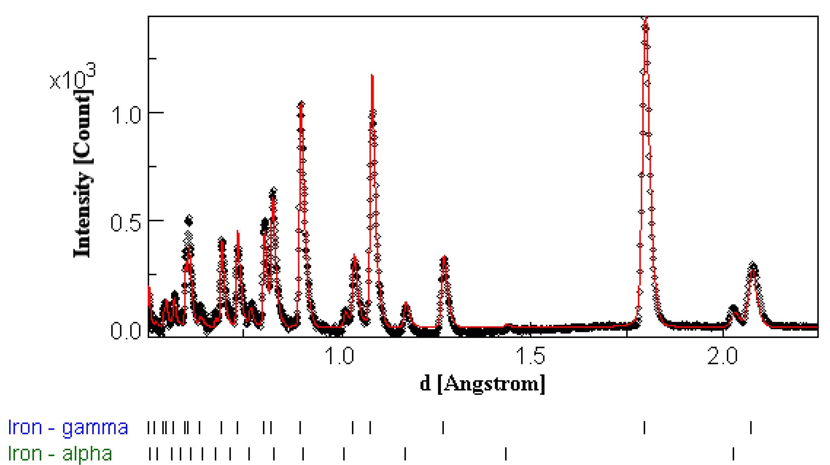
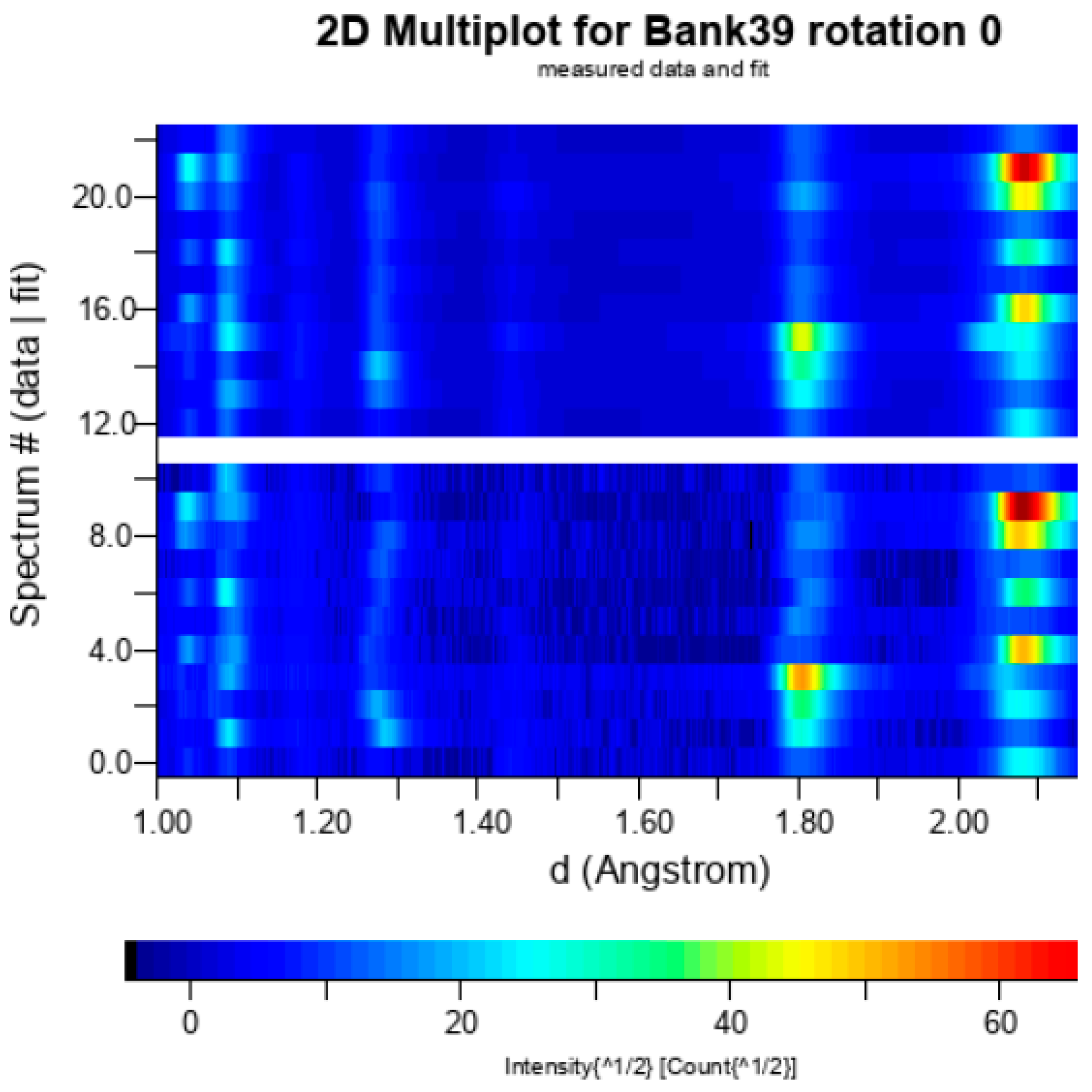
Diffraction data collected from the HIPPO diffractometer were analyzed using the MAUD software for Rietveld refinement. The quality of the refinement was determined by overall quality of fit indicators such as Rwp values as well as graphically by how well the fit agreed with integrated data and observed intensity variations for different detectors were captured in 2D plots of the refinement [35]. Representative plots of diffraction spectra fits and 2D intensity plots are shown in Figure 2 and Figure 3. Specifically, Figure 2 shows that the experimental peak intensities, peak widths and peak positions are well described by our Rietveld analysis model. Figure 3 shows that the relative intensity variations due to the texture of the sample observed experimentally (bottom of Figure 3 labeled “data”) are also well captured by our analysis model (top of Figure 3 labeled “fit”). Such graphical comparisons of experimental data and fit enable judging the quality of the data analysis and the good agreement shown in the figures lends credibility to the reliable determination of the microstructural parameters that are part of the analysis model. Following refinement of raw data pole figures and ODF, analysis was performed using the MTEX toolbox in MATLAB.
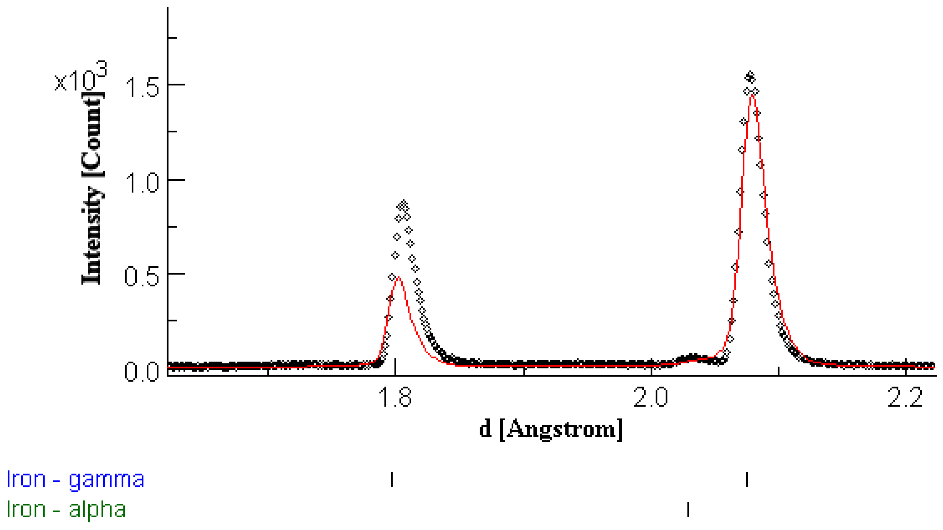
During refinement, substantial mismatch between some γ-phase peaks and the expected peak position was observed as seen in Figure 4. As only some peak positions were misplaced, and because this mismatch was observed in the spectra of individual detectors, this observation would normally signify significant anisotropic lattice strains in the material. However, apparent strains of this sort are known to also occur when sample displacements are greater than 0.1 mm [36]. The large beam diameter used in HIPPO (~10 mm) certainly allows for this sort of error to occur for mm-sized highly oriented grains located on opposite sides of the sampling volume as different hkl reflections detected in a detector originate from different grains with their center of volume, or effective diffraction volume, separated by several millimeters. In the example data shown in Figure 4, the γ-Fe peak that is expected to occur at 1.797 Å is shifted to 1.802 Å. It is important to note that the pattern shown in Figure 4 represents the data from a single detector and that most of the calculated γ-Fe peaks line up well with the data. The peak shift is equivalent to an apparent strain of 0.28% strain using equation 1 [36]. The values for l0 and l1 on HIPPO are 8.85 m and 0.854 m, respectively. Assuming that the separation of the two grains can be approximated as a sample displacement, following the equation 1 the separation between the two grains in this extreme case is ~27 mm. While this estimated value is larger than the sample diagonal (16 mm), the agreement allows to conclude that this effect is indeed the explanation for the observed peak shifts. Potentially, thermal residual stresses may also contribute to the observed peak shifts, but such detailed analysis is beyond the scope of this paper. However, the evidence of grain sizes of several mm indicates that other texture measurement techniques such as EBSD and XRD are not suitable for this material, underlining the value of the unique results obtained in this neutron diffraction study.
ε = ( d d 0 ) d 0 = Δ D I F C D I F C = [ ( l 0 + l 1 ) l 0 + l 1 + θ cot θ ]
Since this effect affects the accurate determination of lattice and peak width parameters, we omit reporting the lattice parameters and parameters derived from the peak width.
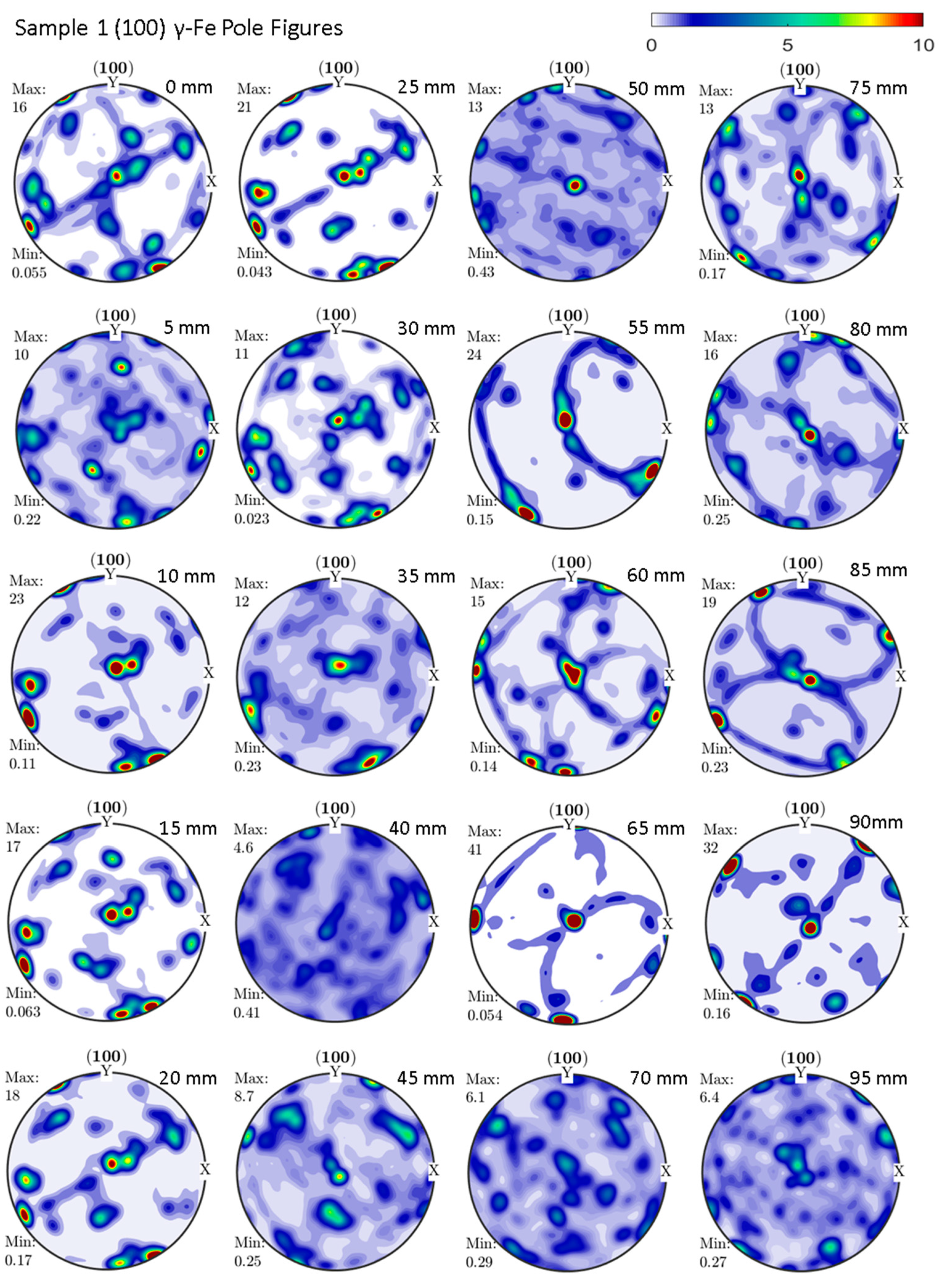
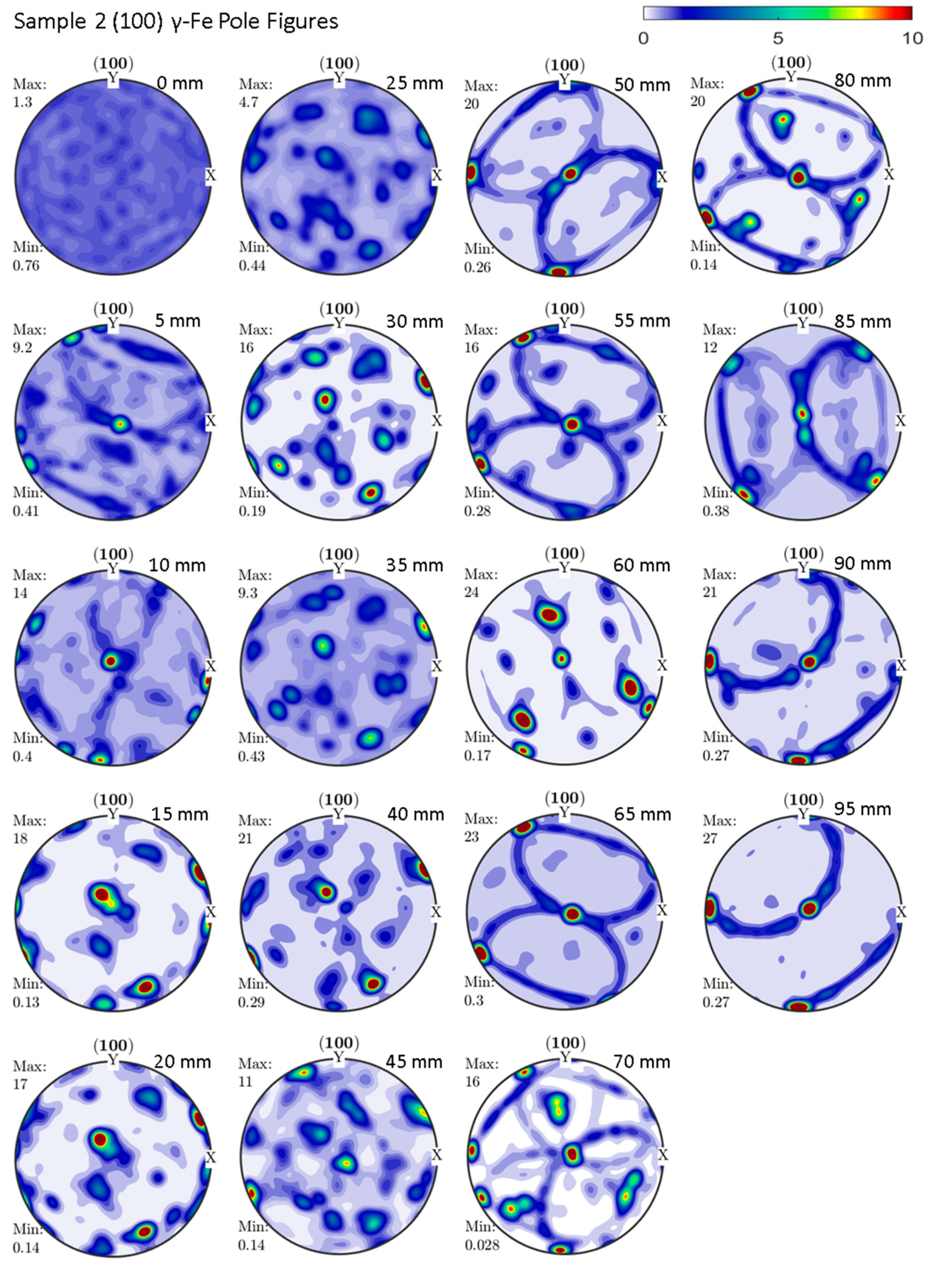
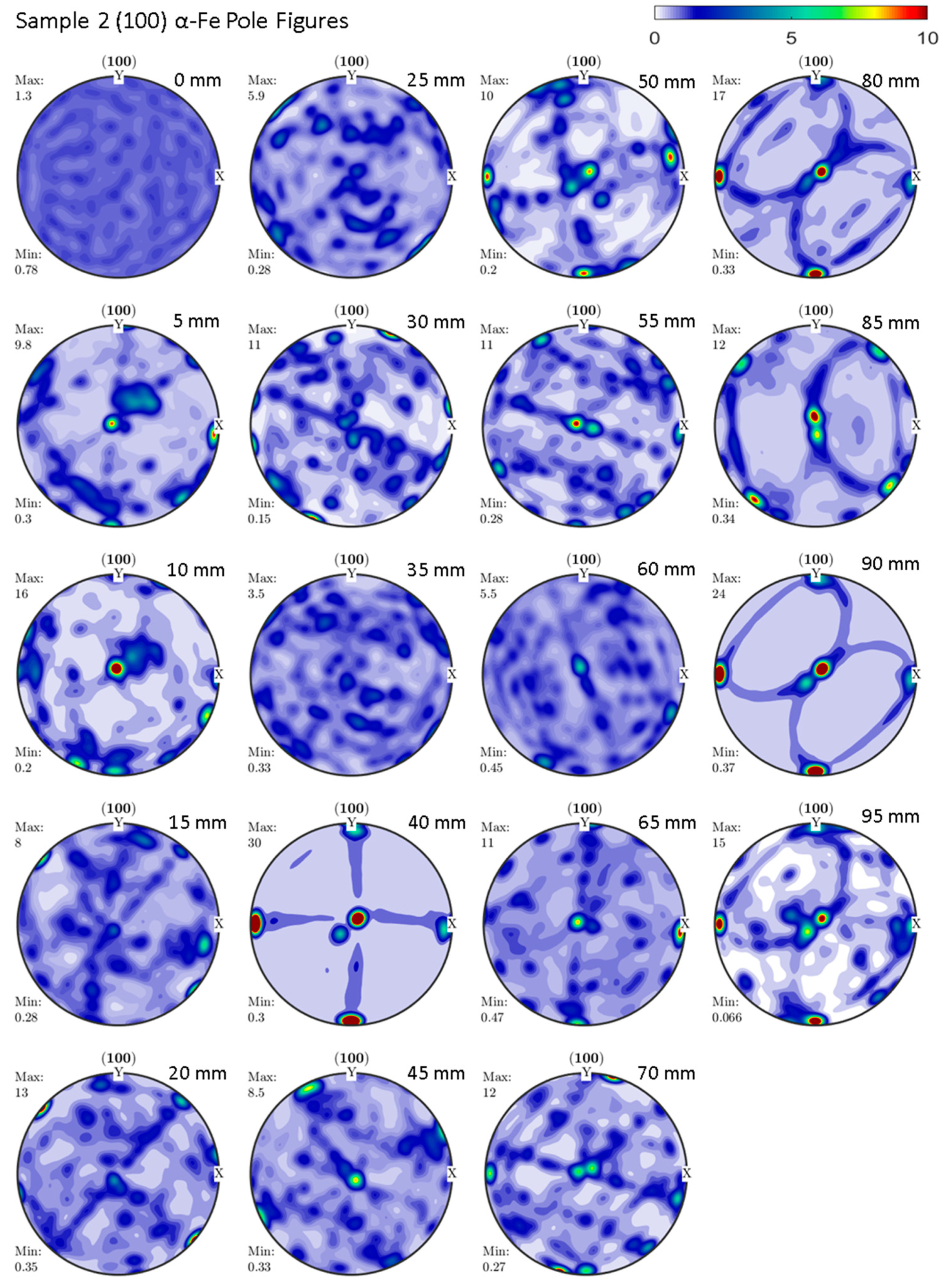
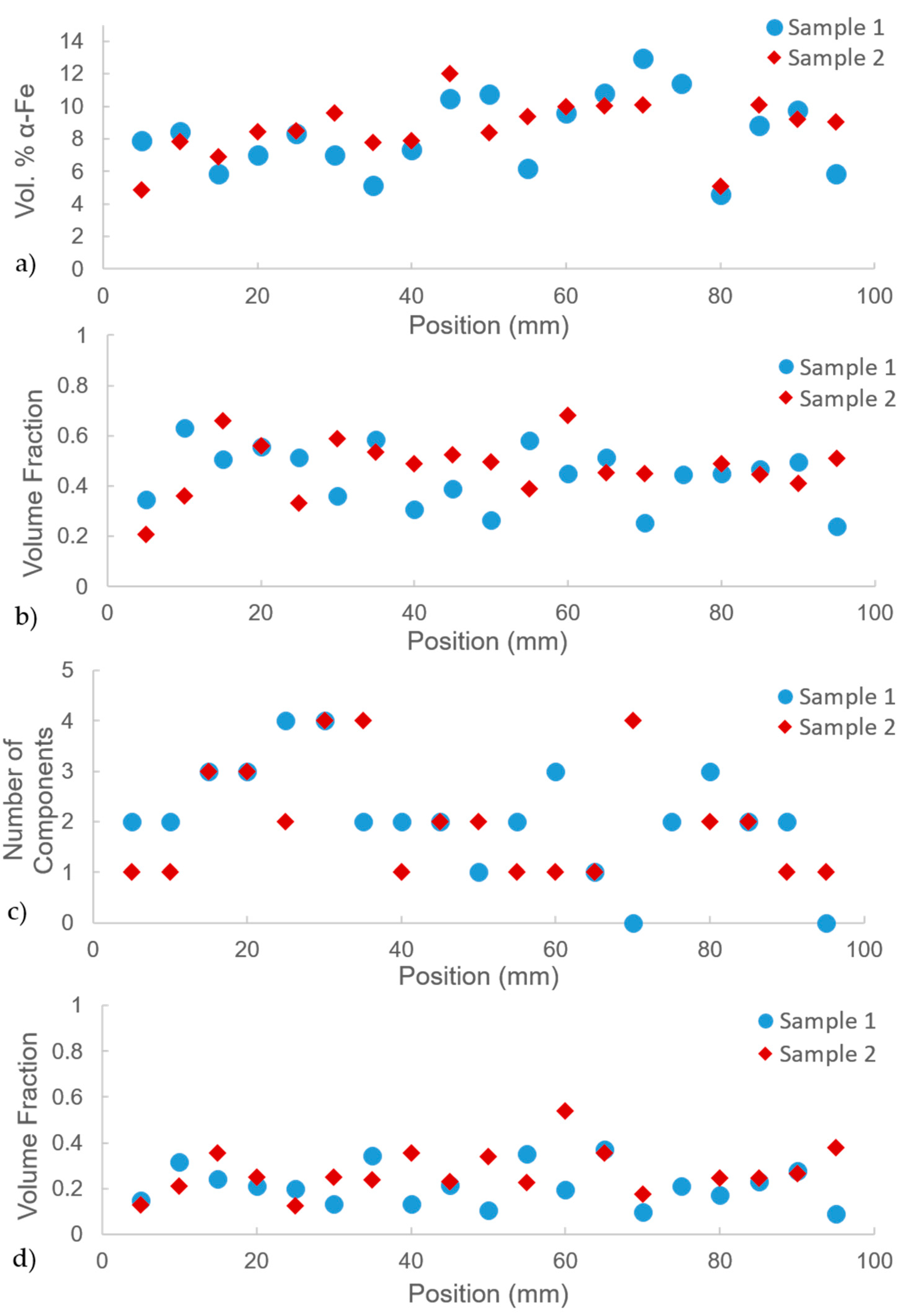
The (100) pole figures for the austenite phase for all measurements on Sample 1 and Sample 2 are shown in Figure 5 and Figure 6, respectively. Strong textures consistent with few large grains, with their (100) poles aligning in or near the center of the pole figure (sample radial direction), dominate the (100) pole figures. The resulting textures appear to be composed of relatively few texture components, resulting in the observed very strong textures. The ferrite phase pole figures from all measurements on Sample 1 and Sample 2 are shown in Figure 7 and Figure 8, respectively. The ferrite phase is also highly textured, with the (100) poles aligning in the radial direction of the sample and also resulting in large textures. This implies that the collections of dendrites that appear in the metallography images in Figure 1 share the same crystallographic orientation. The ferrite phase is significantly less prevalent than the austenite phase, as shown in Figure 9a, composing approximately 5 to 13% by volume.
Analysis of the ODF texture components was performed in MTEX. The volume fraction of the three most intense texture components is plotted for all measurements performed on both samples in Figure 9b. This graph shows that the three most intense texture components account for 25 vol.% to 75 vol.% in each probed slice of the material. Since each slice has a volume of 10 × 12.7 × 2 mm = 254 mm3, this indicates millimeter-sized grains or regions of homogenous texture. As is evident in the pole figures, several grain orientations are almost identical for probed slices 5 mm or in some cases even 10 mm apart, indicating that the grains along the axis are essentially the same. This would indicate a columnar grain structure along the radial axis. No clear trend is observed in the volume fraction of the three most intense texture components over the length of both samples. The number of texture components composing greater than 10% of the measured volume is plotted against measurement position in Figure 9c. This graph shows that the number of major components in both samples varies from one to four. The volume fraction of the largest γ-Fe texture component is shown in Figure 9d. The largest component accounts for 10% to 53% of the observed texture in our measurements. The largest texture component (53% of the probed volume) observed was at 65 mm in Sample 1. The associated (100) pole figure with this point also has the strongest texture of 41 MRD. This is an indication that the resulting textures originate from a small number of single crystals with crystal orientations aligning the (100) axis close to the radial direction of the material.

4. Discussion

The dendritic nature of the ferrite in both steel samples revealed by metallography is consistent with established literature. While most CASS steels commonly exhibit two distinct regions, one with large columnar grains and another with a finer equiaxed structure, Ramuhalli et al. showed that at high magnification, both columnar and equiaxed microstructures are composed of highly oriented primary dendrites that may appear as single grains [3].
Analysis of neutron diffraction data revealed that, even though a fine dendritic microstructure is present, the material is highly oriented with (100) poles oriented in the radial direction of the sample. This is consistent with the study by Ramuhalli et al., using EBSD to show that both columnar and equiaxed regions of the sample were highly textured [3]. They showed that, with respect to CASS pipe that the samples were taken from, (100) poles were oriented approximately 38° from the radial direction for grains in the columnar and equiaxed regions, respectively. Our results support this conclusion, as we observed almost single-crystal behavior over much of the sample, indicating very strong austenite textures throughout the entirety of the samples. We do not, however, observe a texture offset of 38 degrees from the radial direction: as is evident in the (100) pole figures for the γ phase in Figure 5 and Figure 6, the (100) poles in almost all cases are less than 10° misaligned from the radial direction in the center of the pole figures. We also observed somewhat weaker texture in measurements near the edge of the sample, likely due to more randomly oriented grains in the “chill zone” of the austenitic pipe. Phase composition of the sample varied slightly along the length of each sample. Results of this study, showing highly oriented textures throughout the samples in CASS will help further the development of non-destructive ultrasonic techniques for these materials. While a detailed discussion of our results in the context of quality control methods, such as acoustic methods, is beyond the scope of this paper, our dataset can be used to model, e.g., the acoustic response of the material (see, e.g., Evans et al. and Wenk et al. for detailed descriptions of bulk neutron texture results to predict and interpret material response in acoustic measurements) [37,38].
The presence of millimeter-sized grains, resulting in millimeter-sized regions of the same texture, violates the powder diffraction assumption used in Rietveld refinement. As a result, the fit produces parameters derived from peak positions, such as lattice parameters, peak width, crystal size and microstrain; and to some extent, parameters derived from peak intensities, such as phase fractions for ferrite and austenite, are affected by systematic errors. In addition, diffraction from different grains from different locations within our sampling volume leads to significant peak shifts within a single-detector measurement. To correct for this would require 3D resolution of individual grains, as was performed by Cereser et al. [39]. However, that is beyond the scope of this paper.

5. Conclusions

For the first time, bulk textures were obtained from two samples cut along the radial direction from the walls of pipes of cast austenitic stainless steel historically used in the primary cooling loops of nuclear power reactors. Strong textures with (100) poles aligned along the radial direction of the pipe were observed. These textures were shown to be dominated by several large grains on the length scale of several millimeters to ~1 cm. The neutron diffraction results did not reveal any significant gradients along the radius of these materials for the texture strength or phase fractions of ferrite and austenite. Metallography of the samples revealed a fine dendritic structure of ferrite in an austenite matrix, consistent with previous studies. The results of this study will help improve non-destructive evaluation techniques such as ultrasonic testing of these materials in the field.

Author Contributions

Conceptualization, S.C.V. and J.J.W.; methodology, S.C.V.; MAUD analysis automation, D.J.S.; Rietveld and MTEX analysis, M.M.S. and D.J.S.; metallography, C.L. and J.D.Y.; writing—original draft preparation, M.M.S.; writing—review and editing, all authors; visualization, M.M.S.; supervision, S.C.V. and J.D.Y.; funding acquisition, J.D.Y. All authors have read and agreed to the published version of the manuscript.

Funding

This work has benefitted from the use of the Los Alamos Neutron Science Center (LANSCE) at LANL. Los Alamos National Laboratory is operated by Triad National Security, LLC, for the National Nuclear Security Administration of the U.S. Department of Energy under contract number 89233218NCA000001.

Data Availability Statement

The data presented in this study are available on request from the corresponding author.

Conflicts of Interest

The authors declare no conflict of interest. The funders had no role in the design of the study; in the collection, analyses, or interpretation of data; in the writing of the manuscript, or in the decision to publish the results.

References

  1. Jacob, R.E.; Crawford, S.L.; Moran, T.L.; Larche, M.R.; Prowant, M.S.; Diaz, A.A.; Nove, C.A. NDE Reliability Issues for the Examination of CASS Components; Pacific Northwest National Lab.(PNNL): Richland, WA, USA, 2019.
  2. Ruud, C.; Diaz, A.; Anderson, M. Grain Structure Identification and Casting Parameters of Austenitic Stainless Steel (Cass) Piping; PNNL-19002; Pacific Northwest National Laboratory: Richland, WA, USA, 2009.
  3. Ramuhalli, P.; Good, M.S.; Diaz, A.A.; Anderson, M.T.; Watson, B.E.; Peters, T.J.; Dixit, M.; Bond, L.J. Ultrasonic Characterization of Cast Austenitic Stainless Steel Microstructure: Discrimination between Equiaxed-and Columnar-Grain Material—An Interim Study; Pacific Northwest National Lab.(PNNL): Richland, WA, USA, 2009.
  4. Boiler, A.; Code, P.V. Section XI, Rules for Inservice Inspection of Nuclear Power Plant Components; American Society of Mechanical Engineering: New York, NY, USA, 1992. [Google Scholar]
  5. Wenk, H.-R.; Lutterotti, L.; Vogel, S. Texture analysis with the new HIPPO TOF diffractometer. Nucl. Instrum. Methods Phys. Res. Sect. A Accel. Spectrometers Detect. Assoc. Equip. 2003, 515, 575–588. [Google Scholar] [CrossRef]
  6. Takajo, S.; Brown, D.W.; Clausen, B.; Gray, G.T., III; Knapp, C.M.; Martinez, D.T.; Trujillo, C.P.; Vogel, S.C. Spatially Resolved Texture and Microstructure Evolution of Additively Manufactured and Gas Gun Deformed 304L Stainless Steel Investigated by Neutron Diffraction and Electron Backscatter Diffraction; Los Alamos National Lab.(LANL): Los Alamos, NM, USA, 2018; ISSN 0885-7156.
  7. Xu, P.; Tomota, Y.; Arakaki, Y.; Harjo, S.; Sueyoshi, H. Evaluation of austenite volume fraction in TRIP steel sheets using neutron diffraction. Mater. Charact. 2017, 127, 104–110. [Google Scholar] [CrossRef]
  8. Tomota, Y. Crystallographic characterization of steel microstructure using neutron diffraction. Sci. Technol. Adv. Mater. 2019, 20, 1189–1206. [Google Scholar] [CrossRef] [Green Version]
  9. McCusker, L.; Von Dreele, R.; Cox, D.; Louër, D.; Scardi, P. Rietveld refinement guidelines. J. Appl. Crystallogr. 1999, 32, 36–50. [Google Scholar] [CrossRef] [Green Version]
  10. Wenk, H.-R.; Van Houtte, P. Texture and anisotropy. Rep. Prog. Phys. 2004, 67, 1367. [Google Scholar] [CrossRef]
  11. Madsen, I.C.; Scarlett, N.V.; Cranswick, L.M.; Lwin, T. Outcomes of the International Union of Crystallography Commission on powder diffraction round robin on quantitative phase analysis: Samples 1a to 1h. J. Appl. Crystallogr. 2001, 34, 409–426. [Google Scholar] [CrossRef] [Green Version]
  12. ASTM A351/A351M-18e1. Standard Specification for Castings, Austenitic, for Pressure-Containing Parts; ASTM International: West Conshohocken, PA, USA, 2018. [Google Scholar]
  13. ASTM A743/A743M-19. Standard Specification for Castings, Iron-Chromium, Iron-Chromium-Nickel, Corrosion Resistant, for General Application; ASTM International: West Conshohocken, PA, USA, 2019. [Google Scholar]
  14. ASTM A744/A744M-20a. Standard Specification for Castings, Iron-Chromium-Nickel, Corrosion Resistant, for Severe Service; ASTM International: West Conshohocken, PA, USA, 2020. [Google Scholar]
  15. Losko, A.S.; Vogel, S.C.; Reiche, H.M.; Nakotte, H. A six-axis robotic sample changer for high-throughput neutron powder diffraction and texture measurements. J. Appl. Crystallogr. 2014, 47, 2109–2112. [Google Scholar] [CrossRef]
  16. Vogel, S.C.; Hartig, C.; Lutterotti, L.; Von Dreele, R.B.; Wenk, H.-R.; Williams, D.J. Texture measurements using the new neutron diffractometer HIPPO and their analysis using the Rietveld method. Powder Diffr. 2004, 19, 65–68. [Google Scholar] [CrossRef] [Green Version]
  17. Lisowski, P.W.; Schoenberg, K.F. The Los Alamos neutron science center. Nucl. Instrum. Methods Phys. Res. Sect. A: Accel. Spectrometers Detect. Assoc. Equip. 2006, 562, 910–914. [Google Scholar] [CrossRef]
  18. Ino, T.; Ooi, M.; Kiyanagi, Y.; Kasugai, Y.; Maekawa, F.; Takada, H.; Muhrer, G.; Pitcher, E.J.; Russell, G.J. Measurement of neutron beam characteristics at the Manuel Lujan Jr. neutron scattering center. Nucl. Instrum. Methods Phys. Res. Sect. A: Accel. Spectrometers Detect. Assoc. Equip. 2004, 525, 496–510. [Google Scholar] [CrossRef]
  19. Takajo, S.; Vogel, S.C. Determination of pole figure coverage for texture measurements with neutron time-of-flight diffractometers. J. Appl. Crystallogr. 2018, 51, 895–900. [Google Scholar] [CrossRef]
  20. Savage, D.J.; McWilliams, B.A.; Vogel, S.C.; Trujillo, C.P.; Beyerlein, I.J.; Knezevic, M. Mechanical behavior and texture evolution of WE43 magnesium-rare earth alloy in Split-Hopkinson Pressure Bar and Taylor Impact Cylinder Testing. Int. J. Impact Eng. 2020, 143, 103589. [Google Scholar] [CrossRef]
  21. Matthies, S.; Pehl, J.; Wenk, H.-R.; Lutterotti, L.; Vogel, S. Quantitative texture analysis with the HIPPO neutron TOF diffractometer. J. Appl. Crystallogr. 2005, 38, 462–475. [Google Scholar] [CrossRef]
  22. Carpenter, J.; Liu, X.; Darbal, A.; Nuhfer, N.; McCabe, R.; Vogel, S.; LeDonne, J.; Rollett, A.; Barmak, K.; Beyerlein, I. A comparison of texture results obtained using precession electron diffraction and neutron diffraction methods at diminishing length scales in ordered bimetallic nanolamellar composites. Scr. Mater. 2012, 67, 336–339. [Google Scholar] [CrossRef]
  23. Onuki, Y.; Hoshikawa, A.; Nishino, S.; Sato, S.; Ishigaki, T. Rietveld Texture Analysis for Metals Having Hexagonal Close-Packed Phase by Using Time-of-Flight Neutron Diffraction at iMATERIA. Adv. Eng. Mater. 2018, 20, 1700227. [Google Scholar] [CrossRef]
  24. Onuki, Y.; Hoshikawa, A.; Sato, S.; Ishigaki, T.; Tomida, T. Quantitative phase fraction analysis of steel combined with texture analysis using time-of-flight neutron diffraction. J. Mater. Sci. 2017, 52, 11643–11658. [Google Scholar] [CrossRef]
  25. Lutterotti, L. Maud: A Rietveld analysis program designed for the internet and experiment integration. Acta Crystallogr. A 2000, 56, s54. [Google Scholar] [CrossRef] [Green Version]
  26. Wenk, H.-R.; Lutterotti, L.; Vogel, S. Rietveld texture analysis from TOF neutron diffraction data. Powder Diffr. 2010, 25, 283–296. [Google Scholar] [CrossRef] [Green Version]
  27. Lutterotti, L. Quantitative Rietveld Analysis in Batch Mode with Maud. Structures of Minute Crystallites with Exceptional Properties and Frontiers of Powder Diffraction 2011. Available online: http://www.ing.unitn.it/~maud/tutorial/Maudbatch.pdf (accessed on 15 January 2021).
  28. Peng, L.-M.; Ren, G.; Dudarev, S.; Whelan, M. Debye–Waller factors and absorptive scattering factors of elemental crystals. Acta Crystallogr. Sect. A Found. Crystallogr. 1996, 52, 456–470. [Google Scholar] [CrossRef]
  29. Larson, A.C.; Von Dreele, R.B. GSAS—General Structure Analysis System. In Los Alamos National Laboratory Report LAUR 86-748; Regents of the University of California: Oakland, CA, USA, 1994. [Google Scholar]
  30. Bachmann, F.; Hielscher, R.; Schaeben, H. Texture analysis with MTEX–free and open source software toolbox. Proc. Solid State Phenom. 2010, 160, 63–68. [Google Scholar] [CrossRef] [Green Version]
  31. Rafailov, G.; Caspi, E.a.N.; Hielscher, R.; Tiferet, E.; Schneck, R.; Vogel, S.C. Visualization of texture components using MTEX. J. Appl. Crystallogr. 2020, 53. [Google Scholar] [CrossRef] [Green Version]
  32. MATLAB. R2020a; The MathWorks Inc.: Natick, MA, USA, 2020. [Google Scholar]
  33. Abràmoff, M.D.; Magalhães, P.J.; Ram, S.J. Image processing with ImageJ. Biophotonics Int. 2004, 11, 36–42. [Google Scholar]
  34. Papadopulos, F.; Spinelli, M.; Valente, S.; Foroni, L.; Orrico, C.; Alviano, F.; Pasquinelli, G. Common tasks in microscopic and ultrastructural image analysis using ImageJ. Ultrastruct. Pathol. 2007, 31, 401–407. [Google Scholar] [CrossRef]
  35. Toby, B.H. R factors in Rietveld analysis: How good is good enough? Powder Diffr. 2006, 21, 67–70. [Google Scholar] [CrossRef] [Green Version]
  36. Wang, X.-L.; Wang, Y.; Richardson, J. Experimental error caused by sample displacement in time-of-flight neutron diffractometry. J. Appl. Crystallogr. 2002, 35, 533–537. [Google Scholar] [CrossRef] [Green Version]
  37. Wenk, H.-R.; Vasin, R.; Kern, H.; Matthies, S.; Vogel, S.; Ivankina, T. Revisiting elastic anisotropy of biotite gneiss from the Outokumpu scientific drill hole based on new texture measurements and texture-based velocity calculations. Tectonophysics 2012, 570, 123–134. [Google Scholar] [CrossRef]
  38. Evans, J.A.; Sturtevant, B.T.; Clausen, B.; Vogel, S.C.; Balakirev, F.F.; Betts, J.B.; Capolungo, L.; Lebensohn, R.A.; Maiorov, B. Determining elastic anisotropy of textured polycrystals using resonant ultrasound spectroscopy. J. Mater. Sci. 2021, 56, 10053–10073. [Google Scholar] [CrossRef]
  39. Cereser, A.; Strobl, M.; Hall, S.A.; Steuwer, A.; Kiyanagi, R.; Tremsin, A.S.; Knudsen, E.B.; Shinohara, T.; Willendrup, P.K.; da Silva Fanta, A.B. Time-of-flight three dimensional neutron diffraction in transmission mode for mapping crystal grain structures. Sci. Rep. 2017, 7, 9561. [Google Scholar] [CrossRef] [Green Version]
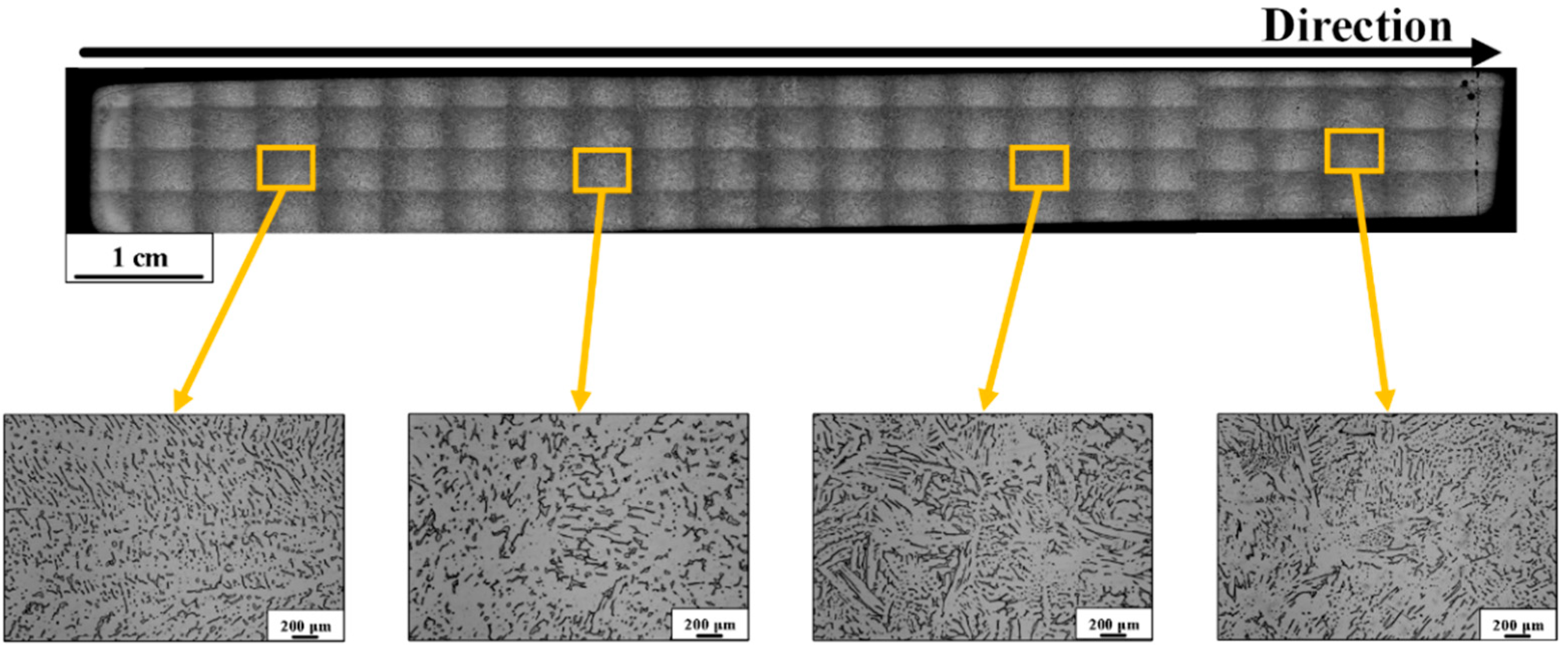
Figure 1. High magnification of CASS steel Sample 1 along the entire length of the sample. Dendritic ferrite in an austenite matrix appears throughout the sample. The square patterns in the photograph are an artefact of the stitching process. Segments are displayed in higher magnification below with the original area highlighted.
Qubs 05 00012 g001
Figure 2. Example diffraction pattern (black) for one measurement taken on CASS steel and the corresponding Rietveld refinement fit (red) with the difference curve below and calculated peak positions for both phases shown as tick marks.
Qubs 05 00012 g002
Figure 3. Example of a two-dimensional contour plot from the 40° detector bank for the first rotation on HIPPO showing clear indication of texture as variation in the intensity of neutrons collected by different detector panels. The Rietveld refinement fit (top) shows good agreement with experimental data (bottom).
Qubs 05 00012 g003
Figure 4. Spectra from the 90 degree detector on HIPPO. Good agreement with the fit and most γ peaks is observed. However, a large peak shift is observed for the γ (200) peak at ~1.8 Å, while the position of the (111) peak at ~2.08 A is well matched.
Qubs 05 00012 g004
Figure 5. Variation in γ-Fe (100) pole figures over the length of Sample 1.
Qubs 05 00012 g005
Figure 6. Variation in γ-Fe (100) pole figures over the length of Sample 2.
Qubs 05 00012 g006
Figure 7. Variation in α-Fe (100) pole figures over the length of Sample 1.
Qubs 05 00012 g007
Figure 8. Variation in α-Fe (100) pole figures over the length of Sample 2.
Qubs 05 00012 g008
Figure 9. Texture analysis by measurement depth showing (a) the volume phase fraction of α-Fe in both samples, (b) the volume fraction of the three most intense largest γ-phase texture components in both samples, (c) the number of γ-phase major texture components composing greater than 10% volume, and (d) the largest γ-phase component volume fraction for both samples.
Qubs 05 00012 g009
Publisher’s Note: MDPI stays neutral with regard to jurisdictional claims in published maps and institutional affiliations.