Article

Flexural Behavior of Concrete-Filled Steel Tube Beams Composite with Concrete Slab Deck

by
Salam Maytham AlObaidi
1,
Mohammed Abbas Mousa
1,
Aqil M. Almusawi
2,
Muhaned A. Shallal
3 and
Saif Alzabeebee
1,*
1
Department of Roads and Transport Engineering, University of Al-Qadisiyah, Diwaniyah 58002, Iraq
2
Civil Engineering Department, University of Kufa, Al Najaf City 54003, Iraq
3
Department of Civil Engineering, University of Al-Qadisiyah, Diwaniyah 58002, Iraq
*
Author to whom correspondence should be addressed.
Infrastructures 2024, 9(10), 187; https://doi.org/10.3390/infrastructures9100187
Submission received: 12 September 2024 / Revised: 15 October 2024 / Accepted: 16 October 2024 / Published: 17 October 2024

Abstract

:
Concrete-filled steel tube (CFST) beams have shown their flexural effectiveness in terms of stiffness, strength, and ductility. On the other hand, composite bridge girders demand durable and ductile girders to serve as tension members, while the concrete deck slab resists the compression stresses. In this study, six composite CFST beams with concrete slab decks with a span of 170 cm were investigated under a four-point bending test. The main variables of the study were the compressive strength of the concrete deck, the size of CFST beams, and the composite mechanism between the CFST girder and the concrete deck. The results showed that the flexural strength and ductility of the composite system increased by 20% with increasing concrete compressive strength. The study revealed that the higher-strength concrete slab deck enabled the CFST beam to exhibit improved flexural behavior with reduced deflections and enhanced resistance to cracking. The findings also highlighted the importance of considering the interactions between the steel tube and concrete slab deck in determining the flexural behavior of the composite system revealed by strain distribution along the composite beam profile as determined using the digital image correlation DIC technique, where a 40% increase in the flexural strength was obtained when a channel section was added to the joint of the composite section.

1. Introduction

The development of steel–concrete composite members, particularly in beam and column applications, has gained significant attention in civil engineering [1,2,3]. One of the types of composite structures that have shown promising results is the concrete-filled steel tube (CFST) beam. Concrete-filled steel tube (CFST) beams have gained popularity in recent years due to their high strength-to-weight ratio, energy absorption capability, high strength, high ductility, durability, and resistance to fire [4,5,6]. On the other hand, the composite behavior of CFST beams with concrete deck slab, where a concrete slab is cast above the CFST tube, provides additional benefits such as improved flexural capacity and reduced deflections [1,7]. The flexural behavior of CFST beams composite with concrete deck slab is influenced by various factors, including the compressive strength of concrete, the size and shape of steel tube, and the thickness and type of slab deck.
Steel elements have sufficient tensile strength but are weak when buckling is governed. However, when steel members are composited with concrete, the buckling failure mode is negligible; therefore, additional stiffening steel plates are not required, which makes composite sections economical and suitable for concrete bridge applications. There are many advantages of using concrete materials in steel tubes: increasing the flexural capacity, stiffness, and rigidity of steel tubes, reducing the local buckling of steel tubes, and increasing the energy absorption and the ductility of the section. Matsumura, Toshio, et al. (2003) [8], and Nakamura et al. (2002) [9,10] were the pioneers in this field, who for the first time, presented a full-scale circular CFST beam composite with a concrete deck by shear connectors that welded to the surface of the steel tube. Nakamura et al. (2004) [11] proposed a simple analytical model to predict the strength of the composite beam with ultra-high light mortar. Mossahebi et al. (2005) [12] carried out a similar experimental work to the studies mentioned above [8,9,10,11]. However, the concrete filling material was replaced with lightweight concrete to reduce the overall weight of the system. Their investigation confirmed the tremendous bearing capacity and the ductility of the composite girder. Later on, Fu et al. (2017) [13] conducted a numerical investigation of the aforementioned composite girders, where a closed-form solution based on moment–curvature and a finite element model was proposed to predict the flexural strength of the composite beam. Nonetheless, part of the concrete in the CFST section had been replaced by polyvinylchloride pipe to form a void, which reduced the weight of the section.
The use of CFST beams has been extensively studied in recent years, and various studies have demonstrated their potential to outperform traditional reinforced concrete beams in terms of strength, stiffness, and durability [14,15,16,17,18,19,20]. M. G. Kalibhat, and A. Upadhyay (2017) [21] carried out a theoretical investigation to study the interaction between the beam and deck slab. The studied parameters were span length, effectiveness of shear connection, and cross-section geometry of steel girder and concrete slab. The study revealed that the deflection of the composite beam increased with the decrease in partial composite action. However, it decreased when the concrete grade of the deck slab increased. The ductility of the shear connector also influences the deflection of the composite beam [4,5] since connectors with reasonable ductility will permit using the long span with large deflection [5].
Some experimental studies have investigated the flexural behavior of CFST beams with varying concrete compressive strength [22,23]. K. A. Farhan, and M. A. Shallal (2020) [24] conducted an experimental study on CFST beams with concrete compressive strength ranging from 35 MPa to 55 MPa. The results showed that the flexural capacity of the CFST beams increased with increasing concrete compressive strength.
Pu et al. (2021) [25] have conducted an experimental and theoretical investigation dealing with CFST truss composites with concrete deck slabs reinforced with ordinary reinforcements and prestressing tendons and tested under negative bending moments with a two-point loading system, the main advantage gained from the prestressing system was controlling the crack width and its distribution, where no significant regain in the elastic and ultimate flexural capacity was obtained.
The shear studs are used as mechanical connectors between the slab and the web. The type of slab deck also plays a crucial role in the flexural behavior of composite beams [26,27,28,29,30,31,32,33,34,35]. S. W. Yoo and J. F. Choo (2016) [14] conducted an experimental study on composite beams using ultra-high-performance concrete (UHPC) slab deck composite with inverted T steel beam, where 50mm and 100 mm slab thickness were used, and stud spacing of 50 mm, 100 mm, 200 mm, and 400 mm were used. The study highlighted that the large spacing of the stud reduced the strength of the concrete deck slab and exhibited axial crack along the steel girder at the top face of the slab. They also performed numerical simulations to investigate the effects of slab deck type (concrete, fiber-reinforced concrete) on the flexural behavior of CFST beams and found that the fiber-reinforced steel slab deck provided the highest flexural capacity.
The flexural behavior of concrete-filled steel tube beam composites with various concrete compressive strengths, slab deck, and various sizes of steel tubes is influenced by multiple factors; the literature suggests that increasing the concrete strength, steel tube size slab deck thickness, and using steel fiber-reinforced concrete in the slab deck can improve the flexural capacity of CFST beams.
This study will contribute to advancing our understanding of the complex interactions between concrete compressive strength, steel tube sizes, and flexural behavior in CFST beams, ultimately contributing to the development of more efficient and sustainable composite structures for various applications in civil engineering.
The main objective of this study is to assess the flexural behavior of composite beams/girders consisting of a rectangular hollow steel tube filled with concrete and composited with a reinforced concrete deck. The composite action is utilized by the mean of shear connectors penetrated through the concrete-filled steel tube with different depths and compressive strength of concrete and, in some specimens, combined with stiffing channel steel sections to improve the bonding mechanism between the CFST beam and concrete deck slab. The study will also investigate the variation in the size of the steel tube, the shear interlocking mechanism, and the concrete strength of the deck. Digital image correlation, DIC, will be applied in the test setup to extract the strain distribution of the composite, specifically the interface between the deck slab and the web, which gives this research the novelty of using this method.

2. Materials and Details of Specimens

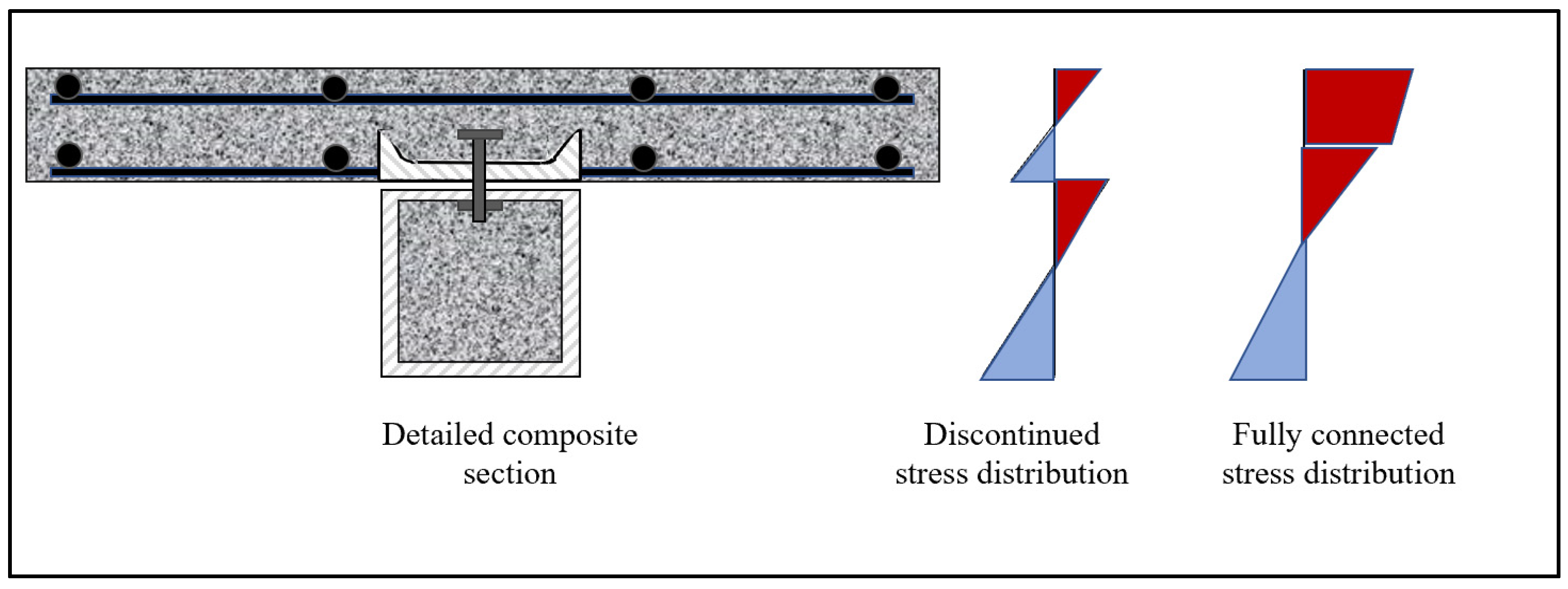
In this study, two main materials were used: concrete and steel. Two types of concrete were utilized: normal-strength concrete with a target compressive strength of 30 MPa that was used to fill the steel tube and some deck slabs, and high-strength concrete with a target compressive strength of 50 MPa that was used for one of the concrete deck slabs. Table 1 shows the details of the specimens. Steel rebar with a diameter of 12 mm was used as the main reinforcement for the slab deck with 150 mm c/c spacing, where the yielding and ultimate strength of the rebar were 450 MPa and 550 MPa, respectively. Steel bolts work as shear studs with a diameter of 15mm and spacing of 150 mm c/c were used to connect the concrete deck with CFST. Steel tubes of 2 mm thickness were used with dimensions of 3 inches (75 mm) and 4 inches (100 mm). Specimens 3″-C50-M1 and 4″-C50-M1 were integrated with channel section of C4″ × 1.58″ × 0.18″ to stiffen the joint section between the CFST and the deck slab, as shown in Figure 1. The composite beams of 1.8 m total length and 1.7 m flexural span length were prepared to be tested under a four-point bending load to investigate their flexural behavior.

2.1. Molding and Casting

The specimens were prepared in two stages: the CFST was cast first with the steel studs fixed inside them at the designed spacing of 150 mm c/c and length of either 50 mm or 65 mm to be embedded inside the concrete deck slab. The concrete deck wooden mold and reinforcement were fabricated and erected over the CFST, Figure 2.

2.2. Test Setup

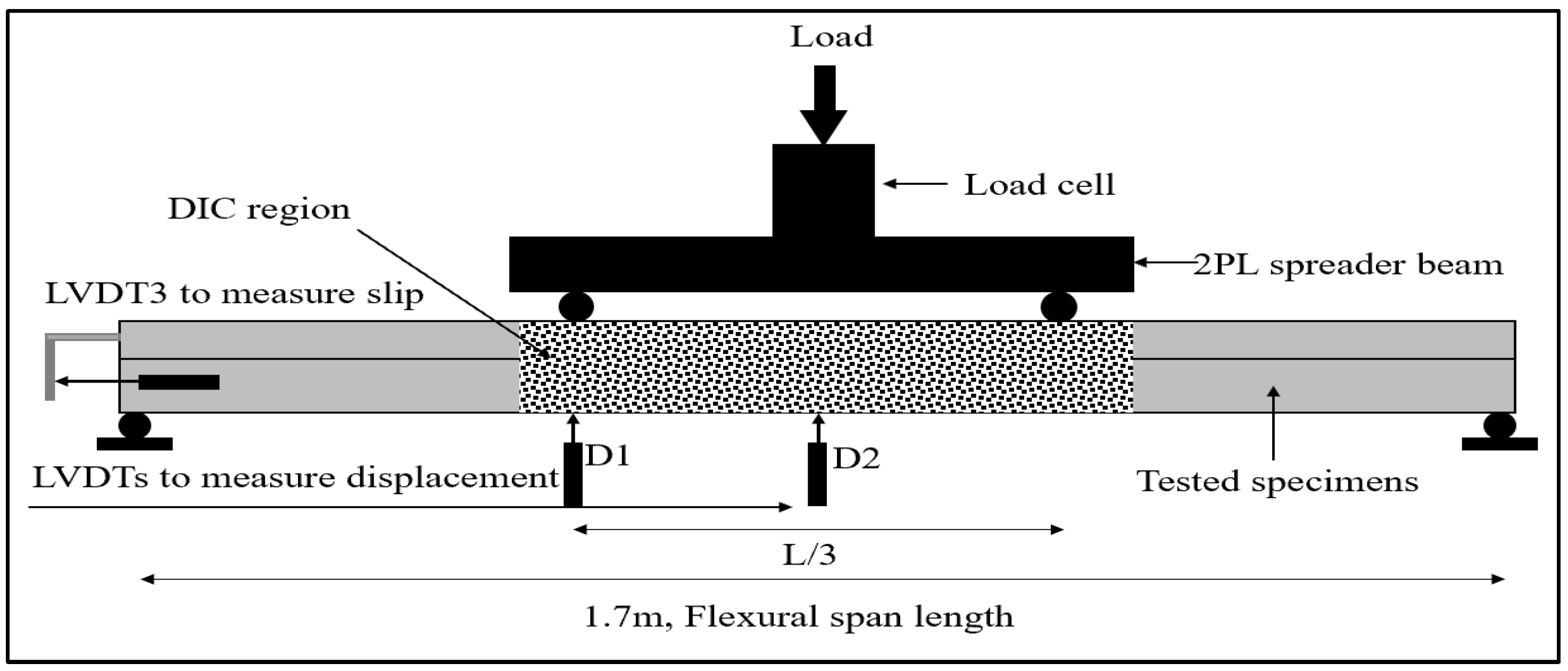
The specimens were prepared to be tested in a four-point load test setup, as shown in Figure 3, with a loading rate of 4 kN/min. The flexural span length of the beam is 1.7 m, where the two-point load is divided into three parts. Three linear variable differential transducers LVDTs were utilized; the first one (D1) was placed under one of the point loads, and the second one (D2) was placed in the middle. These two were used to measure the vertical displacement, and the third one, LVDT3, was placed at the edge of the beam to record the slippage between the CFST and the concrete deck, where the LVDT3 mounted on the CFST, and the tip was projected on a steel plate that was mounted on the deck slab so that the relative horizontal displacement can be recorded. The load was recorded via the load cell, where the displacement versus load and slippage versus the load curves can be obtained, as will be shown later. The test setup was using the DIC measuring technique. The middle of the specimens was painted with random dot patterns, and a high-quality camera with a 24 MP sensor was used to take pictures at specific intervals (every 1 s). Then, images can be used in the GOMTM 2019 DIC software to extract the strain along the test.

3. Results and Discussion

3.1. Load–Displacement Curves

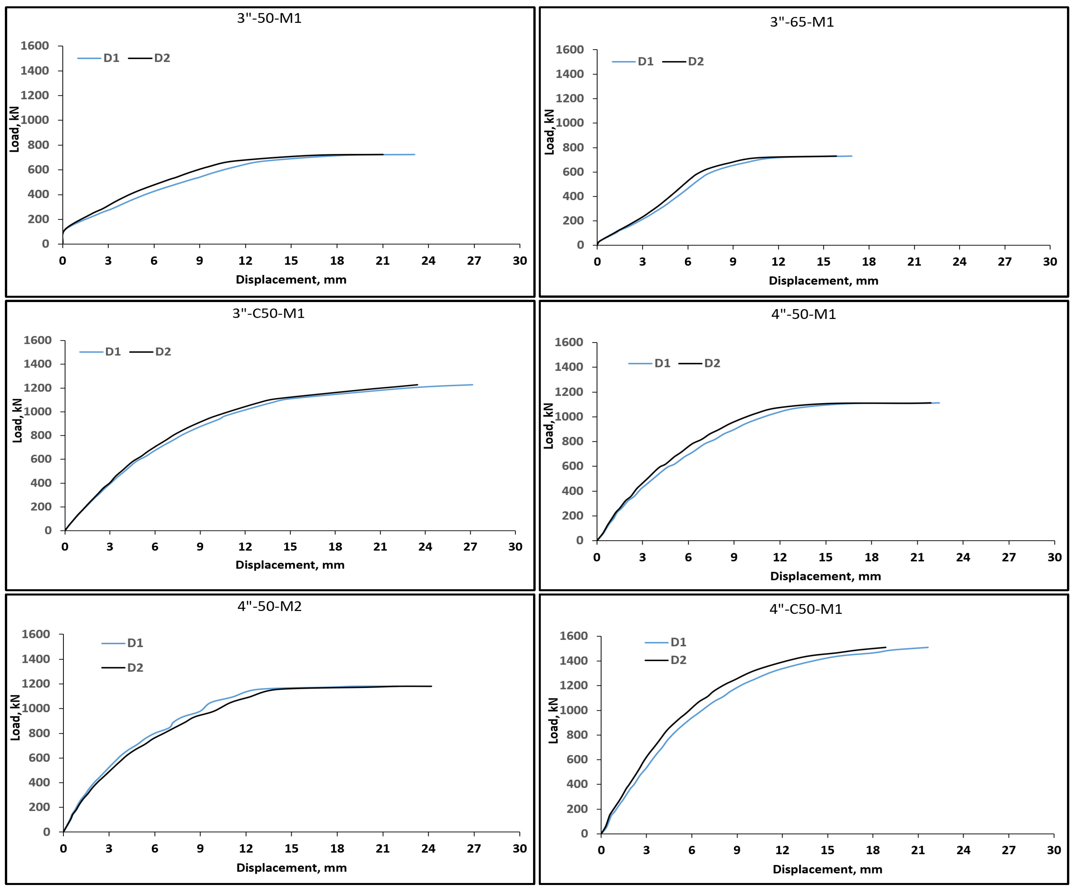
The load–displacement curves of the tested specimens are presented in Figure 4. Each specimen has two curves, which correspond to the reading from LVDT 1 and LVDT 2. The reading from D2 corresponds to the LVDT that is located under the point load; therefore, it is always reading lower than the second LVDT, D1. The addition of the channel section has increased the flexural load capacity for both 4-inch and 3-inch CFST sections, this also reflects on the ductility and energy absorption response where these specimens exhibited higher values for the area under the curve of load–displacement curves, Table 2. The specimens with 65 mm penetrating stud length in the concrete deck slab have shown better performance than specimens with 50 mm stud length; this indicates that the efficiency of composite action between the CFST and the deck slab increases when the penetrating length of the shear stud increases. The failure modes of specimens with stiffening channels and 65 mm penetrating depth of shear studs were compressive failure, which indicates the efficiency of the composites mechanism between the deck slab and CFST sections, Table 2. This could be due to the fact that the large penetrating provides efficient length for the stress developed around the shear stud, as reported by Sun et al. [36]. Increasing the concrete compressive strength has also exhibited higher flexural capacity and ductility. When comparing specimens 4″-50-M1 and 4″-50-M2, the higher compressive strength has probably enhanced the bonding mechanism between the concrete deck slab and the CFST, thus, the failure mode was shifted from slippage/tensile to compressive failure, Table 2, where the latter has higher concrete compressive strength for the deck slab. A higher strength of concrete provides sufficient resistance for the concentrated stresses developed around the shear connecter in addition to the compressive strength carried by the section.
As shown in Figure 4, the readings at the beginning, failure phase of both LVDTS, D1, and D2 are almost the same, and they have some difference in the middle of the load–displacement response, this indicates that the bond between the CFST and the concrete deck slab is sufficient since the difference in the middle due to the sagging behavior of the composite beam. Finally, when the beam reaches close to the ultimate stage, the difference between the values of points D1 and D2 becomes the largest. While points D1 and D2 appear to have similar values on the graph at this stage, this is solely due to the beams having the same ultimate strength. This shared ultimate strength, observed at high deflection steps, causes their load–displacement curves to converge in the Y-direction, creating the illusion of convergence. As a remarkable point, the main attribute of the enhanced flexural behavior of the composite section is the innovative method used to fix the shear studs that connected the CFST and the deck slab. These studs were fixed inside the tube before casting the concrete by making a hole in the top of the steel tube and tightening employing the nut, then casting the concrete materials and also enhancing the bond of the studs with the steel tubes. The shear studs were penetrated inside the concrete deck with different lengths of 50 mm and 65 mm at 150 mm spacing. Specimens 3″-C50-M1 and 4″-C50-M1 were supplied with channel C4″ × 1.58″ × 0.18″ at the junction between the CFST and the concrete deck. These specimens showed the best performance in terms of flexural strength and bond mechanism, where the channel enhanced the bond mechanism between the CFST and the concrete deck. This hypothesis was confirmed by the observation of the DIC measurements, where no slip was detected at the specimens enhanced with channel sections.

3.2. Load–Slip Curves

The load–slip curves were also prepared based on the reading extracted from the LVDT mounted on the side of the beam, as shown in Figure 5. Since the relative slip measured from one side of the beam is related to the half portion of the beam, assuming the slip is symmetric around the center of the beam. Comparing the performance of all specimens, it seems that the specimens with the channel section 4″-C50-M1 and 3″-C50-M1 have the best performance, where they showed zero slip until about 25% and 50% of the maximum applied load, respectively. This indicates that the channel section has stiffened the bond region between the CFST and the deck slab and delayed the initiation of the slip, which reflects on the overall performance of the composite section, as has been seen in the previous section.

3.3. DIC Strain Measuring Technique

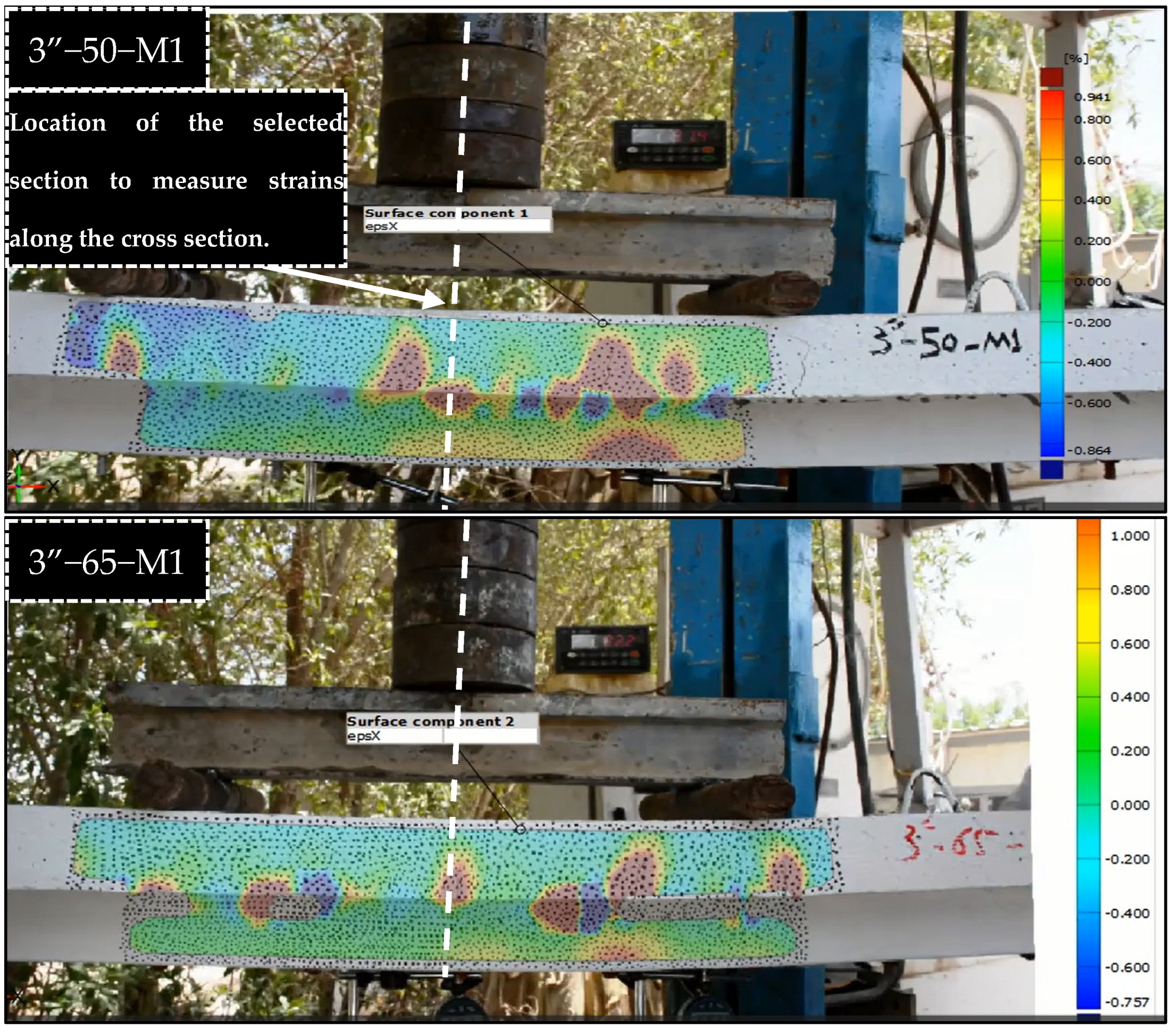
The full-field strain distribution of each tested beam was measured at every second of the test until the ultimate beam failure was measured utilizing the digital image correlation (DIC) technique. The DIC has been used recently to provide full-field and non-contact strain measurement fields of various structures in the laboratory and in-field [37]. The full-field strain distribution of each tested section at the ultimate loading is shown in Figure 6. As shown in Figure 6, multiple cracks were initiated and developed from the lower edge of the slab for all specimens. This indicates that tension strains were fully developed in the CFST beams and then extended to the concrete of the slab deck. Figure 6 clearly shows that CFST beams are in tension as the DIC technique provided the full field of the strains developed on each member. In addition, the number of cracks developed in concrete can be easily indicated and measured using the DIC technique, as shown in Figure 6. The number of cracks and the crack distribution are shown in Figure 6, and it can be noticed that in most cases, regardless of the specimen type, major cracks are developed within the area of the maximum moment, close to the middle section. Further discussion on the strain distribution along the section will be explained in detail in the next section.

3.4. Distribution of Strain along the Cross-Section

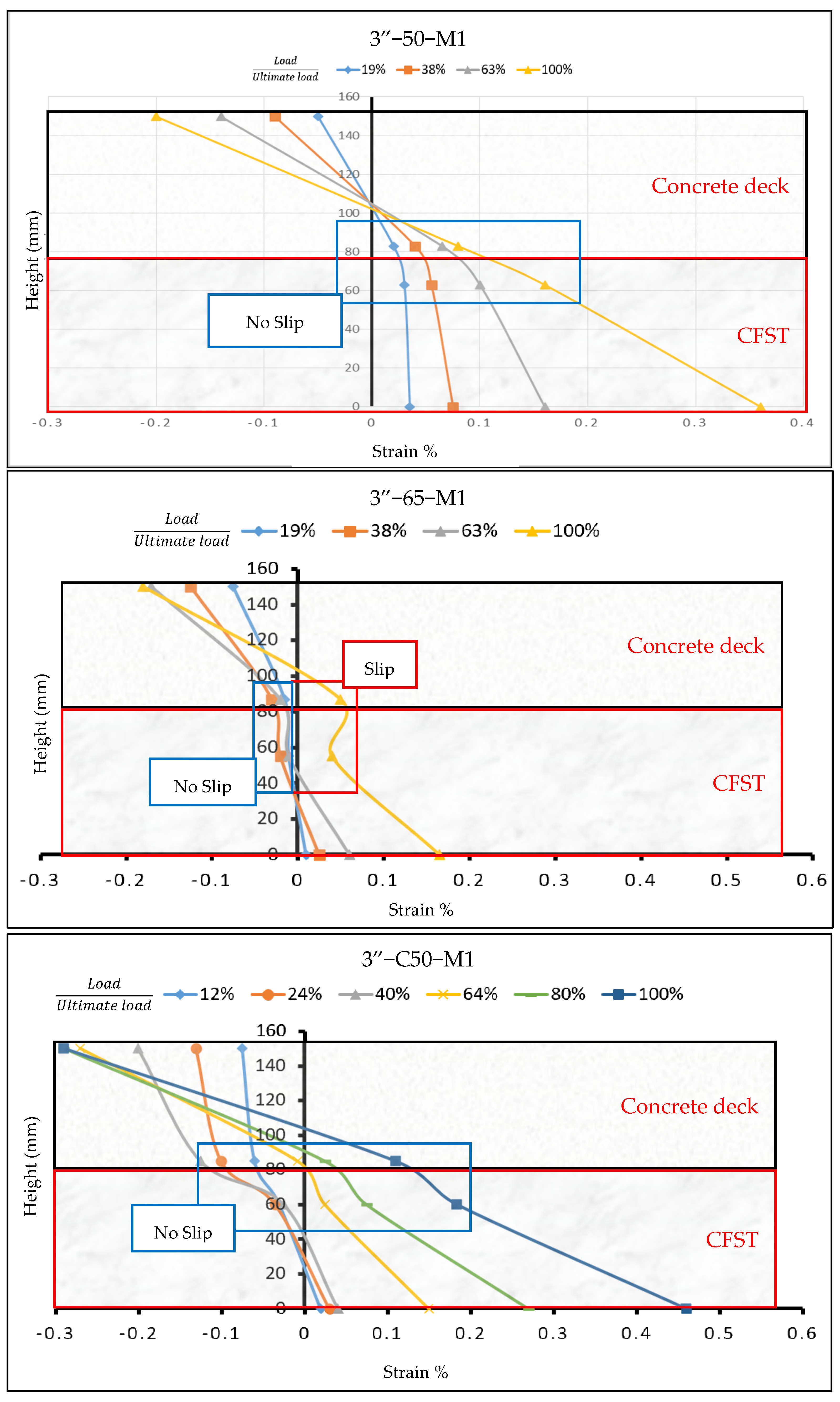
The horizontal strain distribution in the middle of the beams was measured along the composite cross-section as shown in Figure 6, sample (3″-50-M1). Four points are selected to construct the strain profile as follows: top of the slab, bottom of the slab, top of the CFST, and bottom of the CFST. The strain profile for all the samples is demonstrated in Figure 7.
The vertical axis of Figure 7 shows the height of the sample (to scale), and the horizontal axis shows the horizontal strain value in tension and compression. The specimens with the channel sections 3″-C50-M1, 4″-C50-M1, and 3”-50-M1 have shown no slipping between the concrete deck and the CFST beam up to 75% of the ultimate load, as shown in Figure 7. In general, all specimens showed no slipping in the middle of the beams up to 50% of the ultimate load. When opposite strains (tensile and compression) develop at the neighboring sides of the slab and the CFST, strain incompatibility (discontinued) between the two parts of the composite is indicated. The composite beam carries the loads as two separated beams, as shown in Figure 8. However, the added steel channels helped to mitigate the strain incompatibility between the slab and the CFST by distributing and transferring the horizontal stresses and strains uniformly across the multiple developed cracks in the slab, as shown in Figure 8. In addition, the sample with higher concrete strength, M2, showed low tensile strain values compared to other samples where no crack was developed in the middle of the beam. The addition of the stiffening channel perhaps has prevented large deformation in the vicinity of the connection and, therefore, less stress concentrated, and cracks were developed around the shear. It is worth mentioning that these strain profiles in Figure 7 only represent the horizontal strain and the slipping in the middle of the beams and do not necessarily coincide with the strain and the slipping of Figure 5, where slipping was measured at the side of the beam.

3.5. Evolution of Strain with the Load

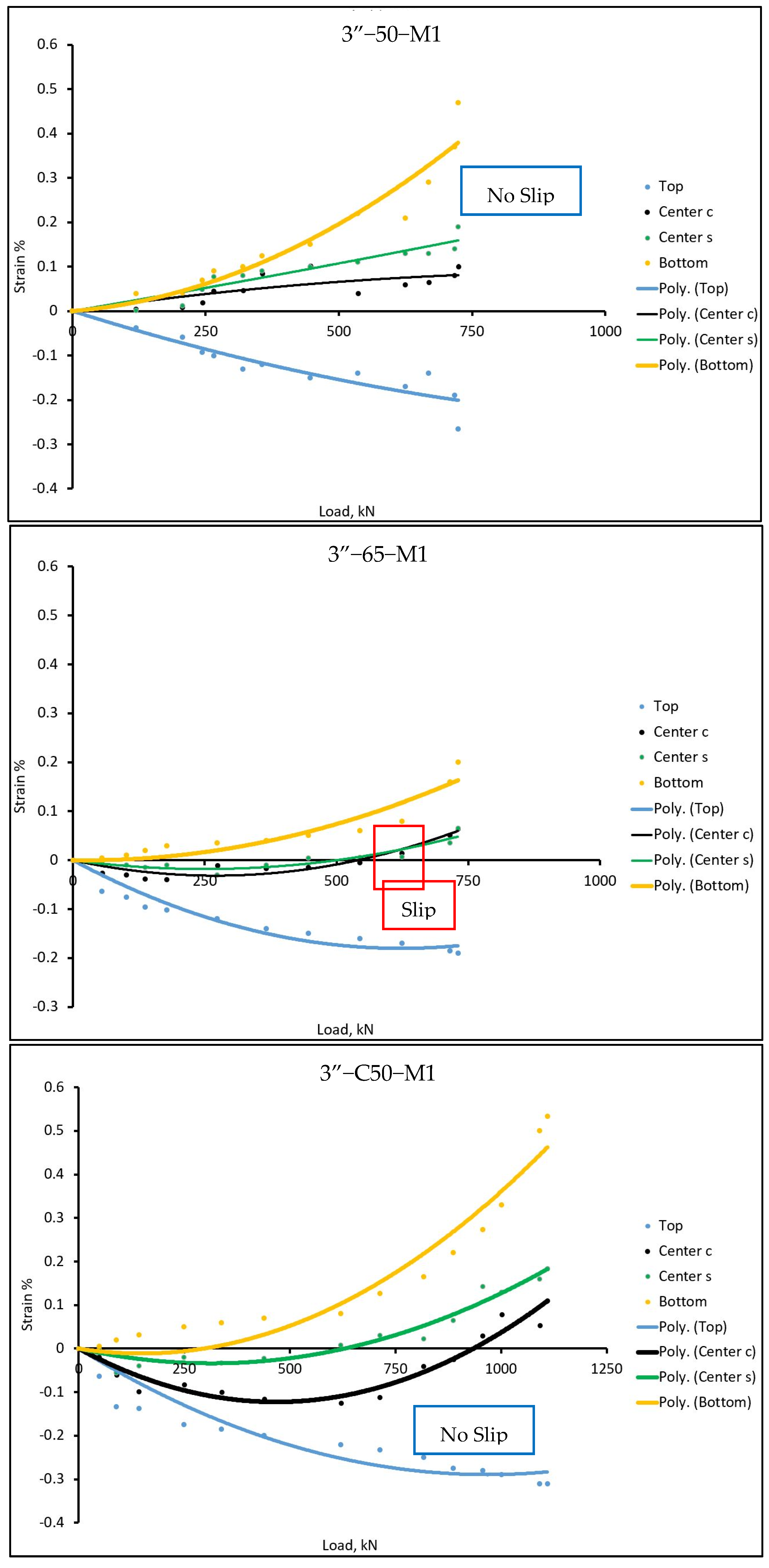
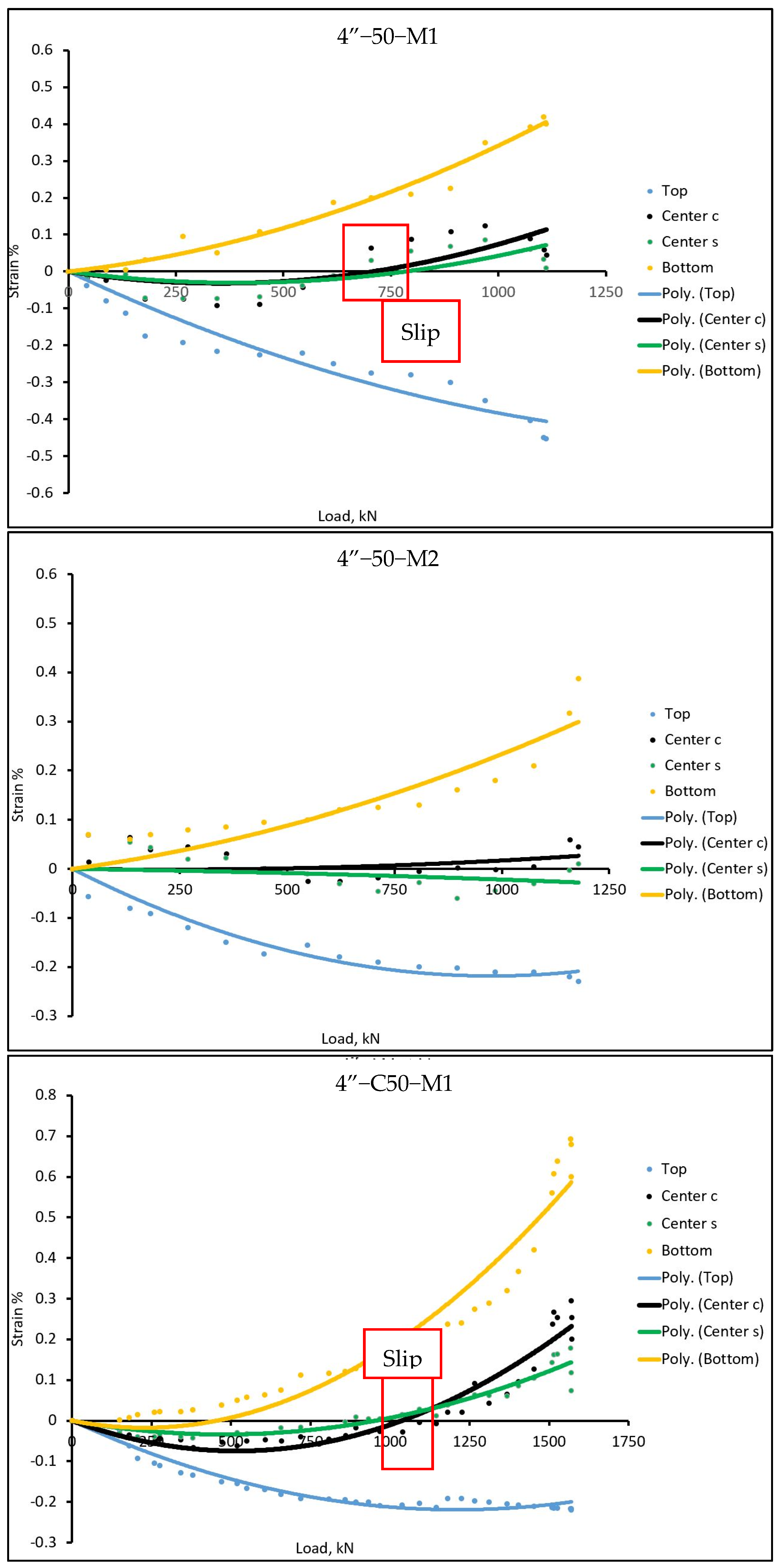
The horizontal strain values versus the load during the test were measured at four locations of the composite cross-section in the middle of the beams. The four locations are (1) the top of the slab (top), the bottom of the concrete slab (center c), the top of the steel CFST (center s), and the bottom of the CFST (bottom). The strain values are modeled by using a 2nd-degree polynomial as the data from the DIC has variations due to the environmental conditions and natural light [38]. Figure 9 shows the compression and tensile strains, respectively, developing at the top of the concrete and the bottom of the CFST while increasing the load. However, the strains in the center of the composite cross-section (bottom of concrete and top of CFST) vary between tensile and compression. The load level corresponding to the intersection of strain values at the bottom of the slab and the top of the CFST, indicating the initiation of slipping, is highlighted within a red box for the black and green data series in Figure 9. A steeper strain curvature is observed in both compressive and tensile regions for beams incorporating channels (samples 3-C50-M1 and 4-C50-M1, Figure 9). This phenomenon is likely attributable to the composite action of the channels with both the concrete and CFST in resisting lateral loads and distributing the loads on larger areas, which can be clearly seen by the multiple cracks developed in the channel-reinforced samples. Furthermore, the beam utilizing high-strength concrete exhibited low strain values at the center of the composite section, indicative of balanced strain development in both compressive and tensile zones.

4. Conclusions

Depending on the results obtained from experimental studies, the behavior of beams composited of CFST and concrete deck slab has been investigated, and the following concluded points can be withdrawn.
1-
Across all tested specimens, the CFST consistently exhibited no local buckling when acting as a flexural member, demonstrating its effectiveness in enhancing flexural behavior. Notably, specimen 40″-50-M1 exhibited a 20% increase in the ultimate load capacity when concrete compressive strength was increased from 30 MPa to 50 MPa and a 40% increase in the ultimate load capacity when the stiffening channel was added to the bonding mechanism compared to reference specimens. The inclusion of steel channels helped reduce strain incompatibility by facilitating the uniform distribution of stresses and strains across developed cracks in the slab, enhancing overall structural performance.
2-
Increasing the compressive strength of the deck slab has increased the flexural capacity of the composite section due to enhancing the bonding mechanism.
3-
The DIC technique showed the full-field strain map for both concrete and steel members and revealed that in some cases, both members are working as two independent members when slipping developed significantly between the two members. The presence of tensile and compressive strains on opposite sides of the slab and CFST indicates strain incompatibility, suggesting that these components functioned independently under load.
4-
The horizontal strain distribution was analyzed at specific points along the composite cross-section. Notably, there was no slipping between the concrete deck and CFST beams up to 75% of the ultimate load for certain specimens, highlighting effective load transfer during this phase.
5-
Specimens with higher concrete strength exhibited lower tensile strain values, correlating with a lack of cracks in the center of the beam. This suggests that increased concrete strength positively impacts the structural integrity and strain response.

Author Contributions

Conceptualization, M.A.S.; methodology, A.M.A.; validation, S.M.A., M.A.M. and S.A.; formal analysis, M.A.M.; investigation, S.M.A. and M.A.M.; resources, M.A.S. and A.M.A.; data curation, S.M.A. and M.A.M.; writing—original draft preparation, S.M.A.; writing—review and editing, S.M.A. and M.A.M.; visualization, S.M.A. and M.A.M.; supervision, M.A.S.; project administration, S.A.; funding acquisition, M.A.S., A.M.A. and S.A. All authors have read and agreed to the published version of the manuscript.

Funding

This research received no external funding.

Institutional Review Board Statement

Not applicable.

Informed Consent Statement

Not applicable.

Data Availability Statement

Data are contained within the article.

Acknowledgments

The authors express their acknowledgments to the University of Al-Qadisiyah, College of Engineering, and the technician Ghanim Daham for his help during testing.

Conflicts of Interest

The authors declare no conflicts of interest.

References

  1. Al-Obaidi, S.; Salim, T.; Hemzah, S.A. Flexural behavior of concrete filled steel tube composite with different concrete compressive strength. Int. J. Civ. Eng. Technol. 2018, 9, 824–832. [Google Scholar]
  2. Dabbagh, N.M.R.; Al-Khafaji, H.H.; Al-Zuhairy, L.H.; Al-Shammari, M.H. A systematic review on CFST members under impulsive loading. Thin-Walled Struct. 2022, 179, 109503. [Google Scholar] [CrossRef]
  3. Hassan, M.M.; Mahmoud, A.A.; Serror, M.H. Behavior of concrete-filled double skin steel tube beam-columns. Steel Compos. Struct. 2016, 22, 1141–1162. [Google Scholar] [CrossRef]
  4. George, C.; Singh, R.S.; Kumar, R.; Kumar, A.; Kumar, P.; Singh, P. Enhancing the fire-resistant performance of concrete-filled steel tube columns with steel fiber-reinforced concrete. Case Stud. Constr. Mater. 2024, 20, e02741. [Google Scholar] [CrossRef]
  5. Han, L.-H. Flexural behaviour of concrete-filled steel tubes. J. Constr. Steel Res. 2004, 60, 313–337. [Google Scholar] [CrossRef]
  6. Yu, M.; Huang, Z.; Liu, Z.; Zhao, W.; Xu, M.; Li, C.; Lin, J. Fire resistance of concrete-filled steel tube columns with preload. Part I: Experimental investigation. Compos. Struct. 2019, 223, 110994. [Google Scholar] [CrossRef]
  7. Alharthi, Y.M.; Almusallam, S.M.; Alsayed, S.H.; Al-Gahtani, F.S. Flexural behavior and capacity of composite concrete-steel beams using various shear connectors. Arab. J. Sci. Eng. 2023, 48, 5587–5601. [Google Scholar] [CrossRef]
  8. Matsumura, T.; Fujii, T.; Nakamura, S.; Sekine, K. Practical application of composite bridge for Shinkansen using CFT. In IABSE Symposium Report; International Association for Bridge and Structural Engineering: Zurich, Switzerland, 2003; Volume 87, p. 9. [Google Scholar]
  9. Nakamura, S. New structural forms for steel/concrete composite bridges. Struct. Eng. Int. 2000, 10, 45–50. [Google Scholar] [CrossRef]
  10. Nakamura, S.; Sekine, K.; Ueda, Y.; Matsumura, T. New technologies of steel/concrete composite bridges. J. Constr. Steel Res. 2002, 58, 99–130. [Google Scholar] [CrossRef]
  11. Nakamura, S.; Hosaka, T.; Nishiumi, K. Bending behavior of steel pipe girders filled with ultralight mortar. J. Bridge Eng. 2004, 9, 297–303. [Google Scholar] [CrossRef]
  12. Mossahebi, N.; Yakel, A.; Azizinamini, A. Experimental investigation of a bridge girder made of steel tube filled with concrete. J. Constr. Steel Res. 2005, 61, 371–386. [Google Scholar] [CrossRef]
  13. Fu, Z.; Li, F.; Zhang, M.; Gao, L. Bending performance of lightweight aggregate concrete-filled steel tube composite beam. KSCE J. Civ. Eng. 2018, 22, 3894–3902. [Google Scholar] [CrossRef]
  14. Yoo, S.-W.; Choo, J.F. Evaluation of the flexural behavior of composite beam with inverted-T steel girder and steel fiber reinforced ultra high performance concrete slab. Eng. Struct. 2016, 118, 1–15. [Google Scholar] [CrossRef]
  15. Nie, J.G.; Zhao, J. Flexural behavior of steel plate-concrete composite beams. Key Eng. Mater. 2009, 400, 37–42. [Google Scholar] [CrossRef]
  16. Lee, J.; Kim, T.; Kim, S.; Lee, K.; Lee, H.; Kim, Y. Characteristics of Flexural Behavior of Composite Section Consisting of Steel Girder with 80MPa High Strength Concrete on Compressive Flange. J. Soc. Disaster Inf. 2017, 13, 455–464. [Google Scholar]
  17. Sharif, A.; Samaaneh, M. Construction Approach to Maintain Composite Action for Continuous Composite Girders. J. Bridge Eng. 2012, 17, 468–474. [Google Scholar]
  18. Heo, B.W.; Bae, K.W.; Moon, T.S. Flexural Capacity of the Encased (Slim Floor) Composite Beam with Deep Deck Plate. J. Korean Soc. Steel Constr. 2004, 16, 235–245. [Google Scholar]
  19. Gholamhoseini, A.; Gilbert, R.I.; Bradford, M. Long-Term Behavior of Continuous Composite Concrete Slabs with Steel Decking. ACI Struct. J. 2018, 115, 119–128. [Google Scholar] [CrossRef]
  20. Hamoda, A.; Abdel-Rahman, A.; El-Hofy, H.; El-Ghandour, A.; El-Sayed, A. Behaviour of Composite High-Performance Concrete Slab-on-Steel Girders Subjected to Hogging Moment. Int. J. Steel Struct. 2016, 16, 1141–1155. [Google Scholar]
  21. Kalibhat, M.G.; Upadhyay, A. Effect of partial shear interaction in steel concrete composite girders. In IOP Conference Series: Materials Science and Engineering; IOP Publishing: Bristol, UK, 2017; Volume 245, pp. 1–8. [Google Scholar]
  22. Nguyen, T.-T.; Le, T.D.; Nguyen, T.-N.; Pham, T.A.; Nguyen, T.N. Behaviour and design of high strength CFST columns with slender sections. J. Constr. Steel Res. 2021, 182, 106645. [Google Scholar] [CrossRef]
  23. Thejeel, M.M.; Shallal, M.A. Performance of concrete-filled steel tube truss girders strength by adding reinforcement. In IOP Conference Series: Materials Science and Engineering; IOP Publishing: Bristol, UK, 2020; Volume 870, p. 012029. [Google Scholar]
  24. Farhan, K.A.; Shallal, M.A. Experimental behaviour of concrete-filled steel tube composite beams. Arch. Civ. Eng. 2020, 66, 119–132. [Google Scholar] [CrossRef]
  25. Pu, B.; Guo, Y.; Shi, Y.; Lu, Z.; Liu, Y.; Wang, L. Mechanical behavior of concrete-filled rectangular steel tubular composite truss bridge in the negative moment region. J. Traffic Transp. Eng. 2021, 8, 795–814. [Google Scholar] [CrossRef]
  26. Dinu, F.; Dubina, D.; Marginean, I. Effect of connection between reinforced concrete slab and steel beams in multi-story frames subjected to different column loss scenarios. In Proceedings of the 4th International Conference on Integrity, Reliability & Failure, Porto, Portugal, 15–17 July 2013. [Google Scholar]
  27. He, J.; Chen, Z.; Yang, Y.; Zhao, H. Experimental study on inelastic mechanical behaviour of composite girders under hogging moment. J. Constr. Steel Res. 2010, 66, 37–52. [Google Scholar] [CrossRef]
  28. Panjehbashi Aghdam, P.; Parent, S.; Dinehart, D.W.; Roy, N. Determination of mechanical properties of headed shear connectors in composite steel beams with precast concrete hollow core slabs: Experimental study. Structures 2024, 69, 107262. [Google Scholar] [CrossRef]
  29. Majdub, M.S.; Baharom, S.; Al Zand, A.W.; Mutalib, A.A.; Hosseinpour, E. Innovation of shear connectors in slim floor beam construction. J. Eng. 2022, 2022, 9705537. [Google Scholar] [CrossRef]
  30. Ma, S.; Chen, L.; Bao, P.; Wang, D. Shear performance and optimization design of beam-slab connector of prefabricated steel–concrete composite structures. Int. J. Civ. Eng. 2022, 20, 1277–1290. [Google Scholar] [CrossRef]
  31. Ding, Y.; Chung, K.F.; Tong, C.C.; Wang, X.D.; Zhou, X.H.; Elghazouli, A.Y. Behaviour of large-diameter high-strength bolted shear connections for prefabricated composite beams. Eng. Struct. 2025, 322, 119002. [Google Scholar] [CrossRef]
  32. Afefy, H.M.; Sennah, K.; Akhlagh-Nejat, H. Experimental and analytical investigations on the flexural behavior of CFRP-strengthened composite girders. J. Constr. Steel Res. 2016, 120, 94–105. [Google Scholar] [CrossRef]
  33. Higgins, C.; Mitchell, H. Behavior of composite bridge decks with alternative shear connectors. J. Bridge Eng. 2001, 6, 17–22. [Google Scholar] [CrossRef]
  34. Pandilatha, P.; Surumi, R.S. Comparitive Study on Flexural Behaviour of Steel Concrete Composite Beam Using Welded and Bolted Shear Connector. Int. J. Civ. Eng. Technol. 2017, 8, 1016–1024. [Google Scholar]
  35. Kang, J.-Y.; Kim, Y.-J.; Lee, S.-H.; Chang, S.-P. Flexural behavior of concrete-filled steel tube members and its application. Steel Struct. 2007, 7, 319–324. [Google Scholar]
  36. Sun, J.; Qiu, H.; Lu, Y. Experimental study and associated numerical simulation of horizontally connected precast shear wall assembly. Struct. Des. Tall Spec. Build. 2016, 25, 659–678. [Google Scholar] [CrossRef]
  37. Mousa, M.A.; Yussof, M.M.; Hussein, T.S.; Assi, L.N.; Ghahari, S. A Digital Image Correlation Technique for Laboratory Structural Tests and Applications: A Systematic Literature Review. Sensors 2023, 23, 9362. [Google Scholar] [CrossRef]
  38. Mousa, M.A.; Yussof, M.M.; Assi, L.N.; Ghahari, S. A Pre-Process Enhanced Digital Image Correlation Approach for Smart Structure Monitoring. Infrastructures 2022, 7, 141. [Google Scholar] [CrossRef]
Figure 1. Cross-section details of the specimens.
Infrastructures 09 00187 g001
Figure 2. Reinforcement details and casting of concrete deck slab.
Infrastructures 09 00187 g002
Figure 3. Test setup of the experimental test.
Infrastructures 09 00187 g003
Figure 4. Load–displacement curves of the specimens.
Infrastructures 09 00187 g004
Figure 5. Load–slip curves of the tested specimens, measured from the side of the beam.
Infrastructures 09 00187 g005
Figure 6. Full-field strain distribution of the tested specimens at ultimate load using DIC.
Infrastructures 09 00187 g006aInfrastructures 09 00187 g006b
Figure 7. Horizontal strain distribution along the section of the tested specimens at ultimate load using DIC.
Infrastructures 09 00187 g007aInfrastructures 09 00187 g007b
Figure 8. Horizontal strain distribution of discontinued and fully connected composite beams, the red colors refer to compression strains and blue colors indicate the tension strains.
Infrastructures 09 00187 g008
Figure 9. Strain evolution with loads at multiple locations of the composite beams.
Infrastructures 09 00187 g009aInfrastructures 09 00187 g009b
Table 1. Tested specimen details.
Specimen’s IDSize of Steel TubeDeck Concrete StrengthTypes of the Studs
(Interlocking Mechanism)
3″-50-M13 inches (75 mm)30 MPa50 mm bolts@150 mm
3″-65-M13 inches (75 mm)30 MPa65 mm bolts @150 mm
3″-C50-M13 inches (75 mm)30 MPaWith channel
4″-50-M14 inches (100 mm)30 MPa50 mm bolts @150 mm
4″-50-M24 inches (100 mm)50 MPa50 mm bolts @150 mm
4″-C50-M14 inches (100 mm)30 MPaWith channel
Table 2. Test summary of the flexural test.
Specimens
ID
Maximum Load
kN
Maximum Deflection
mm
The Area Under the Curve
kN.mm
Max. Slip
mm
Failure Mode
3″-50-M1723.6423.0711,796.625.00Steel tube yielded
3″-65-M1730.7516.858267.585.50Compression failure
3″-C50-M11226.8227.1420,978.135.00Compression failure
4″-50-M11111.2522.4319,143.241.93Tensile and slippage failure
4″-50-M21180.5924.2022,548.407.00Compression failure
4″-C50-M11511.3021.6423,541.534.50Compression failure
Disclaimer/Publisher’s Note: The statements, opinions and data contained in all publications are solely those of the individual author(s) and contributor(s) and not of MDPI and/or the editor(s). MDPI and/or the editor(s) disclaim responsibility for any injury to people or property resulting from any ideas, methods, instructions or products referred to in the content.