Article

Additive Manufacturing, Numerical and Experimental Analyses for Pentamode Metamaterials

by
Panagiotis N. Lymperopoulos
1,
Efstathios E. Theotokoglou
1,*,
Dimitrios Dragatogiannis
2,
Dimitrios Karalekas
3 and
Constantina Matsika-Klossa
3
1
Laboratory of Testing and Materials, Department of Mechanics, School of Applied Mathematical and Physical Sciences, National Technical University of Athens, 5 Heroes of Polytechnion Avenue, Theocaris Building Zografou Campus, 157 73 Athens, Greece
2
Department of Naval Architecture, School of Engineering, University of Western Attica, Agiou Spiridonos 28, 122 43 Egaleo, Greece
3
Laboratory of Advanced Manufacturing Technologies and Testing, University of Piraeus, 80 Karaoli & Dimitriou Street, 185 34 Piraeus, Greece
*
Author to whom correspondence should be addressed.
Infrastructures 2024, 9(10), 172; https://doi.org/10.3390/infrastructures9100172
Submission received: 16 July 2024 / Revised: 7 September 2024 / Accepted: 24 September 2024 / Published: 29 September 2024

Abstract

:
Pentamodes are lattice structures composed of beams. Their main property is the low ratio of the shear to bulk modulus, making them suitable for aerospace, antiseismic, and bioengineering applications. At first, in our study, pentamode structures were fabricated using three-dimensional printing and were tested in a laboratory. Then, computational analyses of bulk strength have been performed. In addition, several preliminary computational analyses have been considered, comparing different pentamodes’ dimensions and topologies in order to understand their behaviour under different loading conditions. Experimental results have been compared with the numerical results in order to validate the forces applied to the lattice structures. Our new contribution is that for the first time, the experimental and numerical results are investigated up to the failure of the specimens, the effective Young’s modulus has been calculated for different pentamode lattice structures, and our results are also compared with analytical equations.

1. Introduction

Over the last few years, mechanical metamaterials have attracted significant attention due to their novel design, combining hierarchical architecture with material size effects at the micro/nanoscale [1]. The research in this field is inspired by several natural materials, such as bone, nacre, enamel, and wood, which demonstrate high stiffness, high strength, and high toughness in combination with a very low density. By tuning a material’s architecture along with its microstructure, unique property combinations not found in conventional engineering materials (metals, ceramics, polymers, and composites) can be achieved [1,2]. Examples include exotic and mechanical metamaterials, which may present a negative Poisson’s ratio and negative compressibility [2].
Lattices (such as pentamodes) are metamaterials with a highly ordered three-dimensional architecture, which are created by periodically repeating a unit cell lattice composed of beams or rods [1]. Pentamodes are three-dimensional (3D) lattice structures composed of bi-cone beams, which were introduced as a subcategory of mechanical metamaterials by Christensen [3] and Milton and Cherkaev [4]. They are named ‘solid waters’, because they exhibit decoupling of bulk and shear moduli; that is, they can have high bulk modulus and low shear modulus [3,4].
The main characteristic of pentamodes is the low value of the ratio shear to bulk modulus [5,6,7,8], which makes them suitable for a wide range of applications from bioengineering applications (bone healing, muscle healing, etc.) [9,10,11] to wave guiding, aeronautical applications (empennage, wings, fuselage design, etc.) [12], and vibrations isolation (anti-seismic design, elastodynamic cloaking, soundproofing, etc.) [13,14,15,16,17,18,19,20,21,22,23,24].
Nowadays, the manufacturing of pentamodes is feasible due to the advancement of 3D printing technologies, which did not exist in the 1990s [25]. Pentamodes have been manufactured since 2012 utilizing 3D printing technology [26,27,28]. Furthermore, pentamodes have been manufactured for a wide range of applications including buckling and crack propagation [13,14,15,16,17,18,19,20,21,22,23,24,25,26,27,28]. Therefore, it is necessary to understand their behaviour under different loading conditions [29,30].
An established 3D printing technology is the selective laser sintering (SLS) technique [30,31,32,33]. According to this additive manufacturing (AM) technique, the material, which may be a powder polymer, is selectively sintered by a laser beam, layer by layer. The cross-section is derived from a computer-aided design (CAD) file or a 3D scan. This 3D printing technique has advantages, such as the printing of complex structures with complex geometry characteristics and the manufacturing of parts with high strength and stiffness. A great disadvantage of the method is the rough surface of the manufactured parts, but with post-processing techniques, this disadvantage is eliminated. In addition, the technique consumes a high amount of energy due to the laser scanning. For this reason, a laser pulse is preferred.
The experimental testing of new materials, such as pentamode metamaterials, is essential for understanding their behaviour. Pentamode metamaterials have high bulk strength. For this reason, the behaviour of pentamodes under compressive loading is a very interesting topic.
At first pentamodes were studied analytically by Christensen [3], Milton and Cherkaev [4], who calculated the Young’s and shear moduli. The advance of numerical methods and computer power resulted in the study of pentamodes using techniques such as the finite element method. The majority of studies are oriented around the experimental, computational, and analytical evaluation of pentamodes. The finite element analyses provided the opportunity to study a wide range of pentamode structures [5,6,8,9,10,11,12,13,14,15,16,17,18,19,20,21,22,23,24,25,26,27,28]. In addition, with the introduction of 3D printing, complex structures such as pentamode lattice structures became feasible to manufacture. Thus, a wide range of experiments may be considered for pentamode lattice structures in order to validate the experimental results with those from analytical and numerical studies [7,26,27,28,29,30,31,32,34,35,36,37,38].
Our study is divided into two parts. First, four specimens from two batches were manufactured using the SLS technique [32,33]. The specimens were compressed in a tensile-compression machine in the laboratory. A prescribed displacement is applied on the pentamode structure’s upper surface, whereas the bottom surface is fully constrained. The reaction force is measured until the pentamode structure fractures. Then, the pentamode structure is numerically confronted using the finite element method, and the experimental results are compared with the numerical ones. In conclusion, the behaviour of different pentamode specimens is numerically studied, and the results are compared with those obtained from experiments. The comparison between the experimental and numerical results is performed up to the failure of the specimens in contrast with previous studies, and very interesting results arise. Finally, the results were also compared with those from analytic solutions.

2. Materials and Methods

2.1. Pentamodes Structures

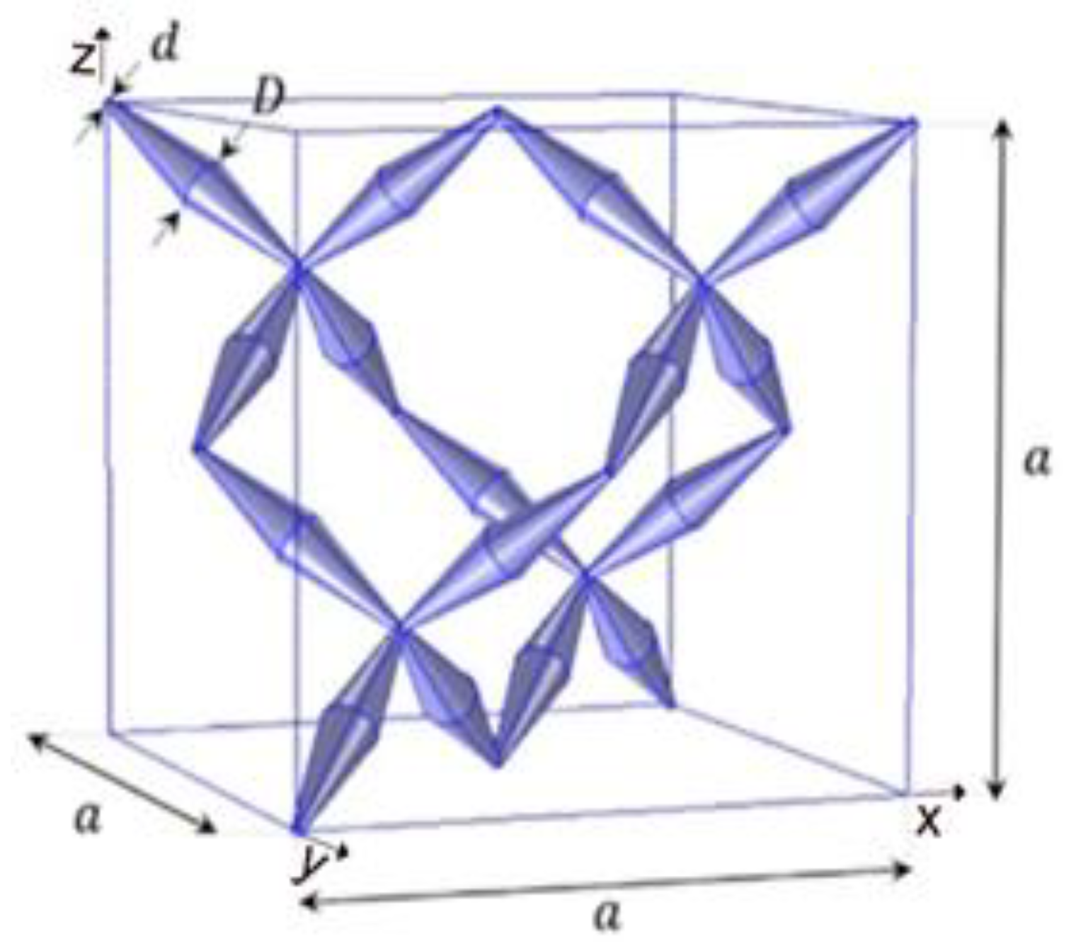
In this study, a typical pentamode unit cell was used (Figure 1).
The pentamode unit cell that has been used in our study is the Face Center Cubic (FCC) or Diamond type [6], which consists of bi-cone beams. The pentamode specimens (Figure 2) have the dimensions given in Table 1 and consist of 2 unit cells towards the x-axis ( n x = 2 ) and 2 unit cells towards the y- and z-axis ( n y = n z = 2 ), where d is the small diameter, D is the wide diameter, and α is the main dimension of the pentamode.

2.2. Fabrication Process

The first batch of specimens was fabricated using an additive manufacturing process. The SLS 3D printing technology was chosen due to its capability to deliver high-resolution prints, which was important for experimenting with different strut diameters and minimising the need for support structures. Clear resin V4 [39] was used as a printing material. The CAD model was created using the 3D software PTC Creo Parametric 9 Student Edition [40]. The PTC Creo Parametric [40] is a powerful software for implicit topological modelling. Boundary representation is also a powerful modelling tool but is not used for modelling lattice structures. After exploring different unit cell dimensions and the repeating patterns, a unit cell with dimensions D = 4 mm, d = 1.43 mm, and α = 30 mm was designed, as shown in Figure 2a (Table 1). A ball matching the d diameter was placed at the junctions of the struts to seal any gaps. The unit cell was then repeated in a 2 × 2 array, n x = n y = n z = 2 . Additionally, on the top and the bottom of the specimen, two plates of 1 mm thickness from the same material were placed to facilitate the experimental process. The finalized CAD design was exported as a binary stereolithography file (STL).
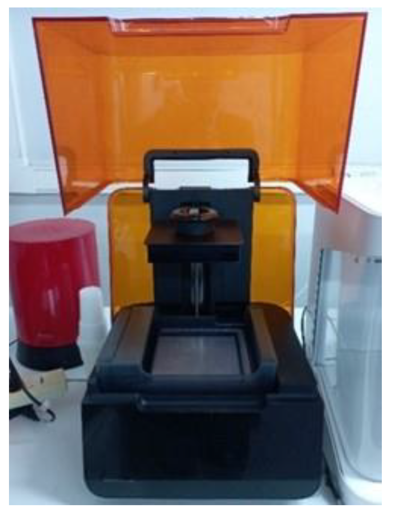
The STL was imported into PreForm v.3.40.1, the proprietary slicing software compatible with the Form 3+ printer (Figure 3). The model, after the analyses from the aforementioned software, has 710 layers with 0.1 mm thickness. The volume of the model is 40.36 mL. The estimated printing time is 4 h and 15 min. In Figure 3, the 3D printer is presented as ready to begin the manufacturing project. During the setup, the model was oriented sideways, using a high-resolution printing setting and minimising support structures and touchpoint size. The limited supports ensured minimal contact with the struts and thus reduced the risk of damaging the printed object when removed.
Post-processing of the printed specimens involved several steps. First, the objects were removed from the printing base. Subsequently, each specimen was immersed in an isopropyl alcohol (IPA) bath for 30 min to remove any residual uncured resin and prepare it for further processing. The support structures were removed using forceps, followed by another rinse in a second IPA bath. To harden and further cure the resin, the printed specimens were placed in an ultraviolet (UV) chamber and exposed to UV light at the highest setting for 30 min. This process ensured the accurate fabrication of the specimens while maintaining the structural integrity of the delicate features.
In the sequel, a second batch of specimens (Figure 2b, Table 1) was designed and manufactured using the aforementioned procedure.

2.3. Material

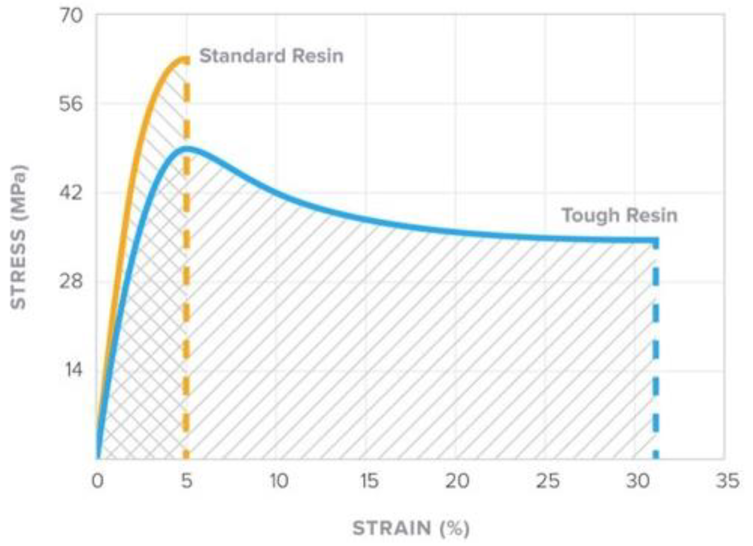
Pentamodes were manufactured using Clear V4 resin from Formlabs [39]. The stress–strain curve of Clear V4 resin is depicted in Figure 4.
In Figure 4, the standard and tough resin curves are presented. The Clear V4 [39] is a standard resin that has been cured with the ultraviolet (UV) process and shows high ultimate strength. However, the material fails as brittle at 5% strain, while the tough resin has lower ultimate strength and fails as ductile at 30% strain. In this research, the Clear V4 [39] standard resin curve was used, and according to the stress–strain curve, the material has the properties presented in Table 2.

2.4. Experimental Setup

In this study, the Zwick Testing Machines Ltd., model Z2.5/TN1S, Ulm, Germany, was used. The tensile-compression machine comprises two compressive plates. The specimen was placed between the two compressive plates. A pre-described displacement was applied to one surface while the other was fully constrained. The applied displacement increases with a rate of 10 mm/min in order to be considered pseudo-static loading conditions. In addition, the displacement was measured. The experiment stopped when the specimen failed. The compression uniaxial tests were performed at room temperature (25 °C). Force and elongation measurements were recorded electronically and the resulting force–displacement compressive curves were calculated.
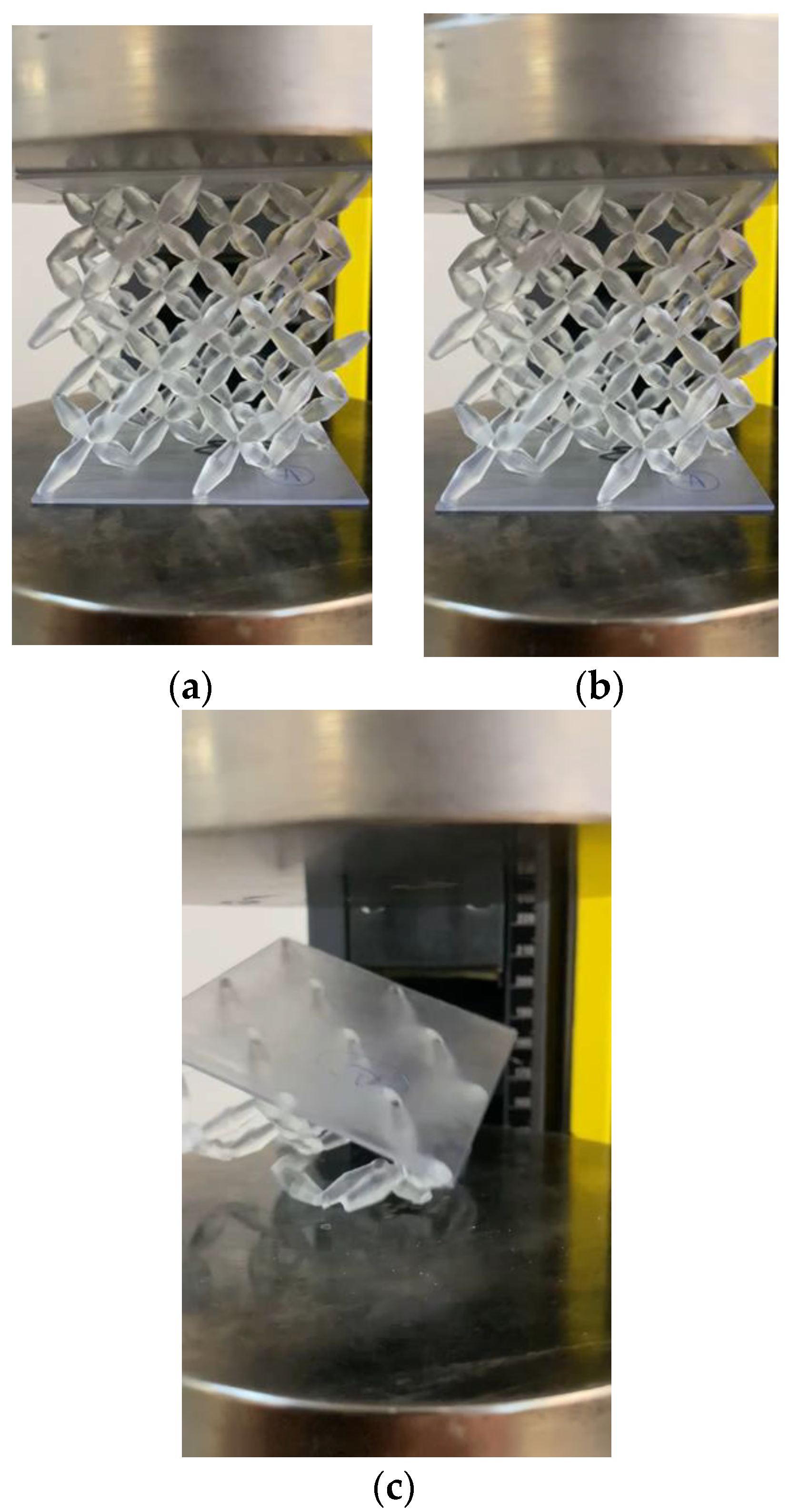
The experimental setup is presented in Figure 5. At first in Figure 5a, the pentamode specimen is presented without loading. In Figure 5b, the displacement applied to the pentamode specimen increases and, finally, in Figure 5c, the specimen has failed. It was noted that pentamodes failed at the beam connections. Each batch consists of 4 specimens. The results for each batch of specimens were combined in order to create a single experimental curve.

2.5. Computational Analysis

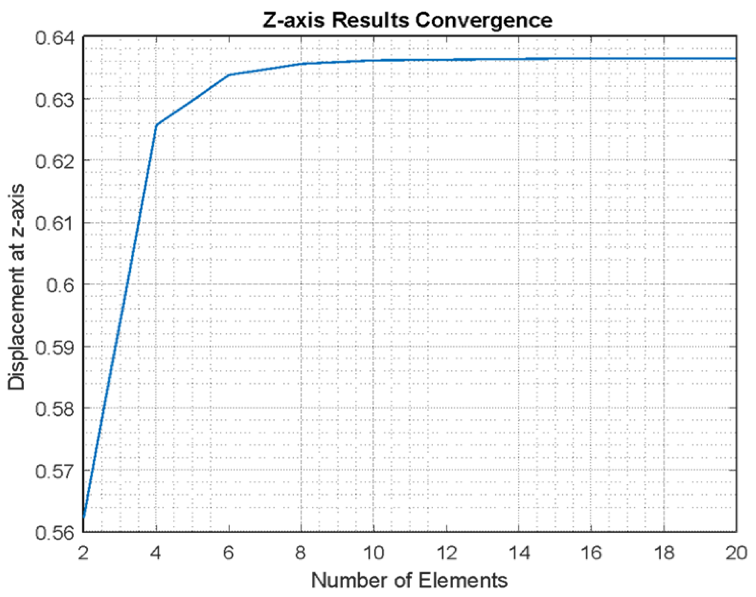
Pentamodes were modelled with the finite element analysis software ANSYS 2021 R1 [41]. The element used was the BEAM189 [41], which is a 3 node beam element, with 6 degrees of freedom at each node. In addition, tapered elements, TAPER [41], were used in order to better model the pentamode bi-cone beams. A pentamode unit cell was considered to have D = 4 mm, d = 1.43 mm and a = 30 mm (Figure 2a), and the material was Clear V4 [39]. In order to study the convergence of our model, a compressive force F = 1.5 kN was applied at the nodes of the upper surface of the pentamode towards the z-axis, while the bottom surface nodes were fully constrained. Figure 6 presents the results for the displacement of the upper surface. It is observed that the results converge after 16 elements in each beam. In our study, 20 elements in each beam were considered.
In the finite element analyses of our study, first, infinitesimal displacements (small displacements) and linear material behaviour were considered. In addition, geometrical nonlinearities have also been considered with large displacement analyses. The material nonlinearity has also been applied using the bilinear material response. The material is considered to yield according to the Von Mises criterion [41].

3. Results

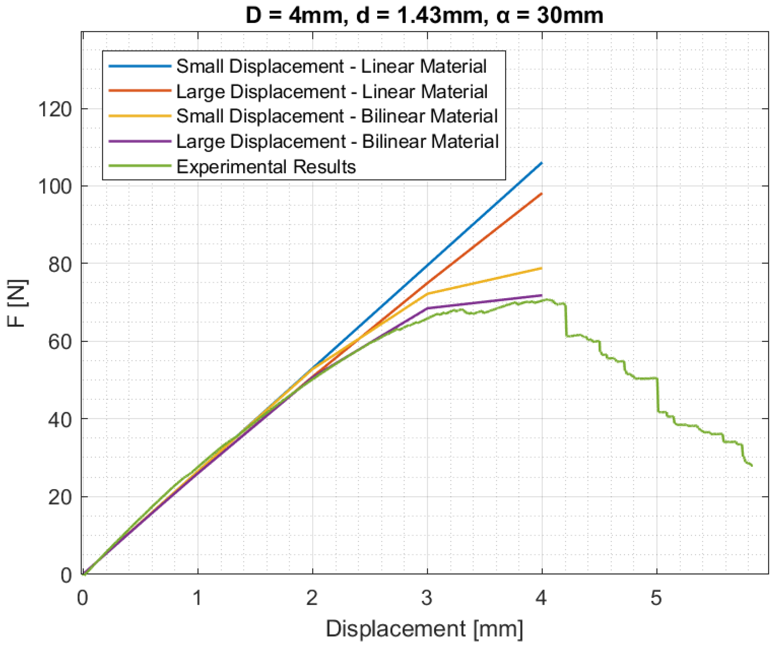
Figure 7 presents the pentamodes of the first batch of specimens (Table 1) and the results from the finite element analyses under different compressive displacements applied at the top surface nodes z = n z   ×   a = 60   mm , considering the bottom surface nodes z = 0 fully constrained.
The plots in Figure 7 show that the numerical and experimental results for the first batch of specimens almost coincide until failure in the case of large displacement and bilinear material analysis [41]. The results from the second batch of specimens are presented in Figure 8.
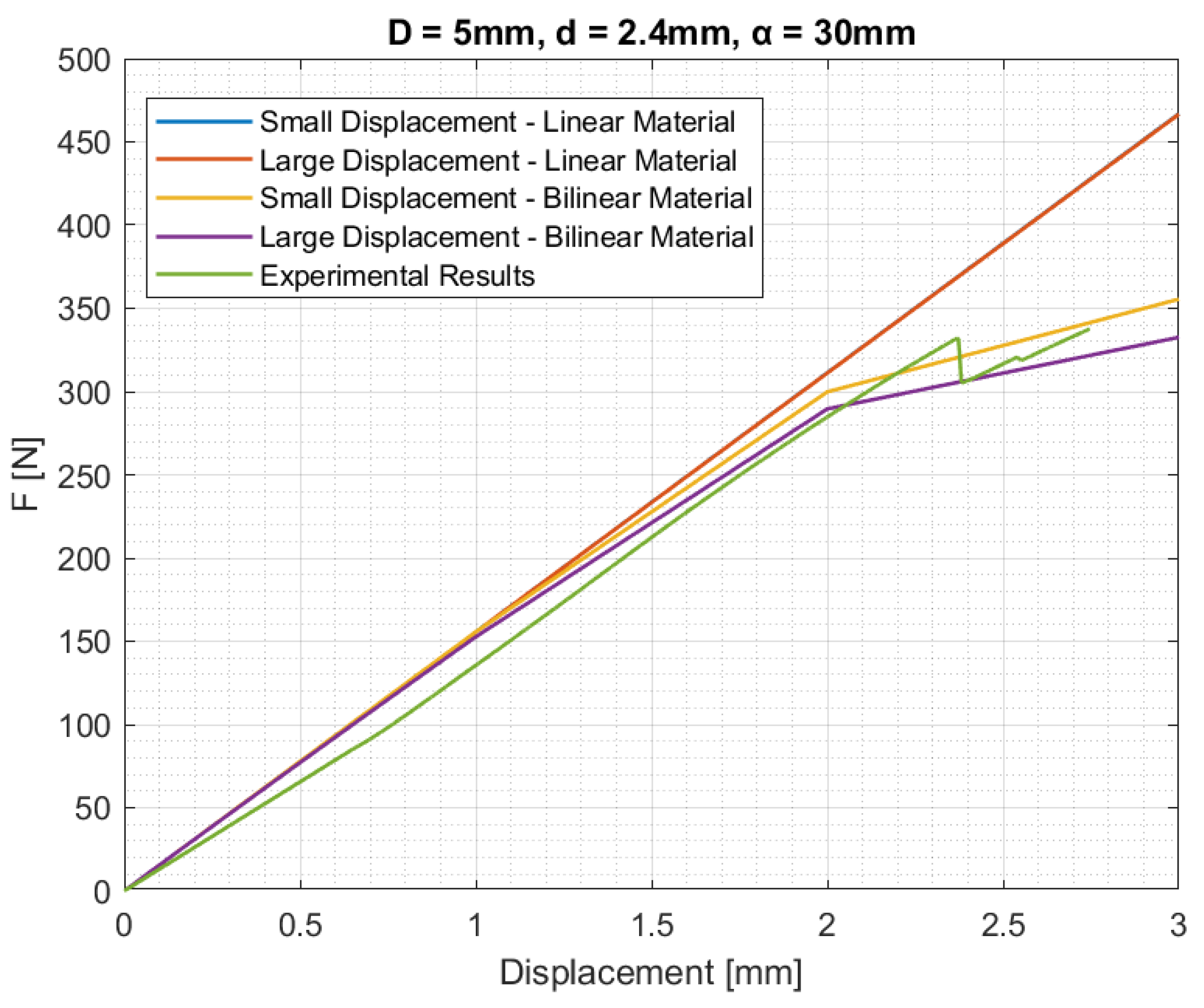
Similarly, for the second batch of specimens, according to the plots in Figure 8, the numerical and experimental results almost coincide in the case of large displacement and bilinear material analysis. However, in Figure 8, small deviations between the numerical and experimental results are observed up to 1.5 mm, which may be due to the prestressing effect, which does not appear for the first batch of specimens (Figure 7). The prestress is the consideration of a preload of 1/100 of the maximum load defined in the machine in order to have a better grab on the plates. The deviation in the second batch may be due to the existence of some defects in the specimens. From the experiments, stress relaxation issues are not observed.
In the sequel, the pentamode behaviour was studied numerically (Figure 9) for constant D = 4   mm and different small diameters d = 1.43   mm 2.4   mm in the case of large displacements and bilinear material analyses. In addition, the case D = 5   mm ,   d = 2.4   mm is examined correspondingly to the second batch of specimens.
According to the plots in Figure 9, the small diameter d of the bi-cone beams appears to make a significant contribution to the pentamode’s strength. It is also observed that the results for the different d = 1.6 ,   1.8 ,   2.0 ,   2.2 ,   2.4   mm are between the two experimental results for the two batches of specimens. It should be noted that the pentamodes with the same small diameter d = 2.4   mm and different diameters D = 4 ,   5   mm appear to have approximately the same strength, whereas the force–displacement curve appears to have discrepancies.
Furthermore, the effective Young’s moduli E e , for the different diameter d (Figure 9), calculated by the following Equation (1) [5,21], are presented in Table 3.
E e = F h δ A ,
where F is the total reaction force at the nodes of the bottom surface of the pentamodes, h = n z   ×   a is the pentamode height, δ is the applied displacement, and A is the area of the pentamode where the displacement is applied. In our study, E e represents the ratio of the average stresses to the average strains in the body when subjected to pure compression.
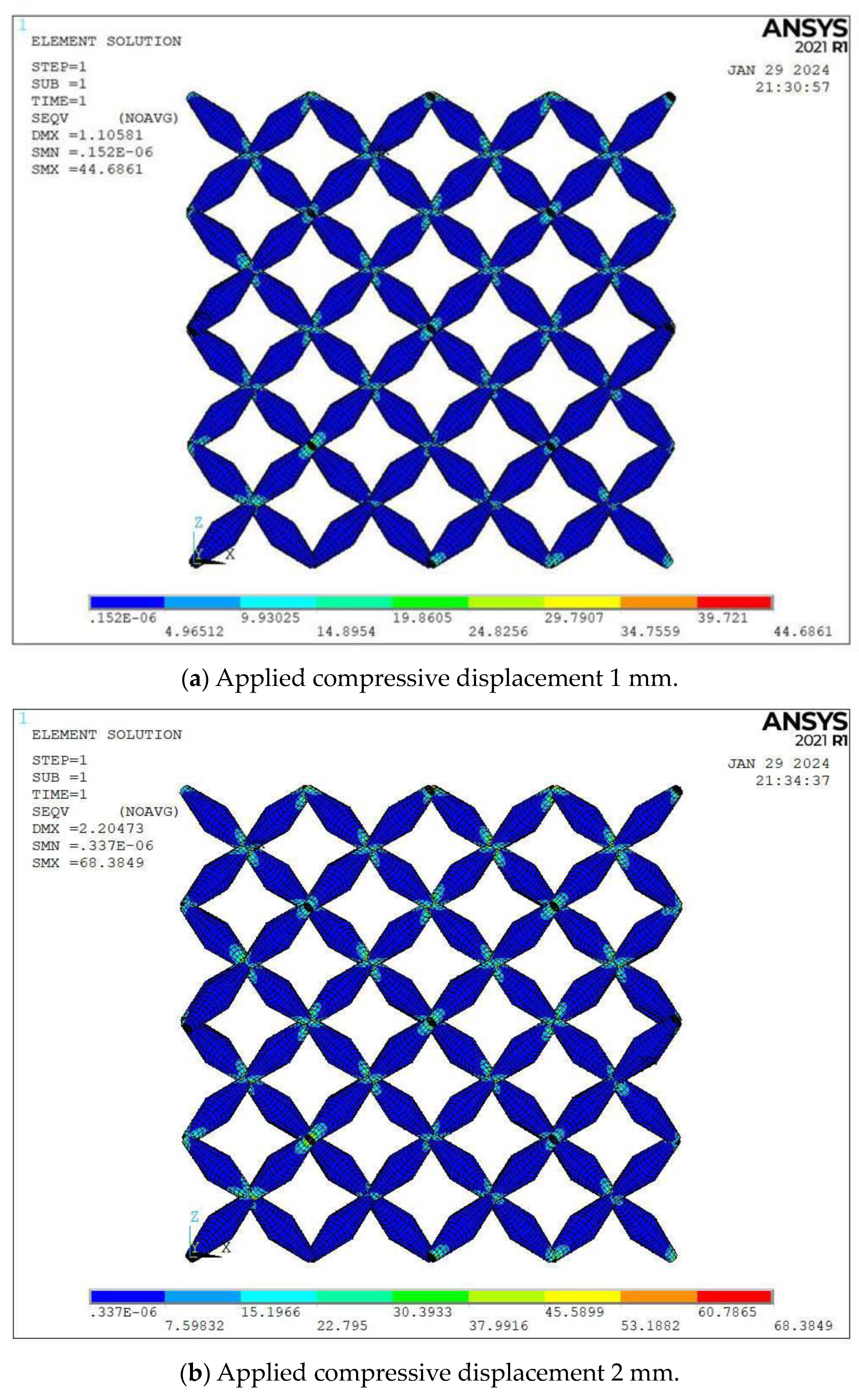
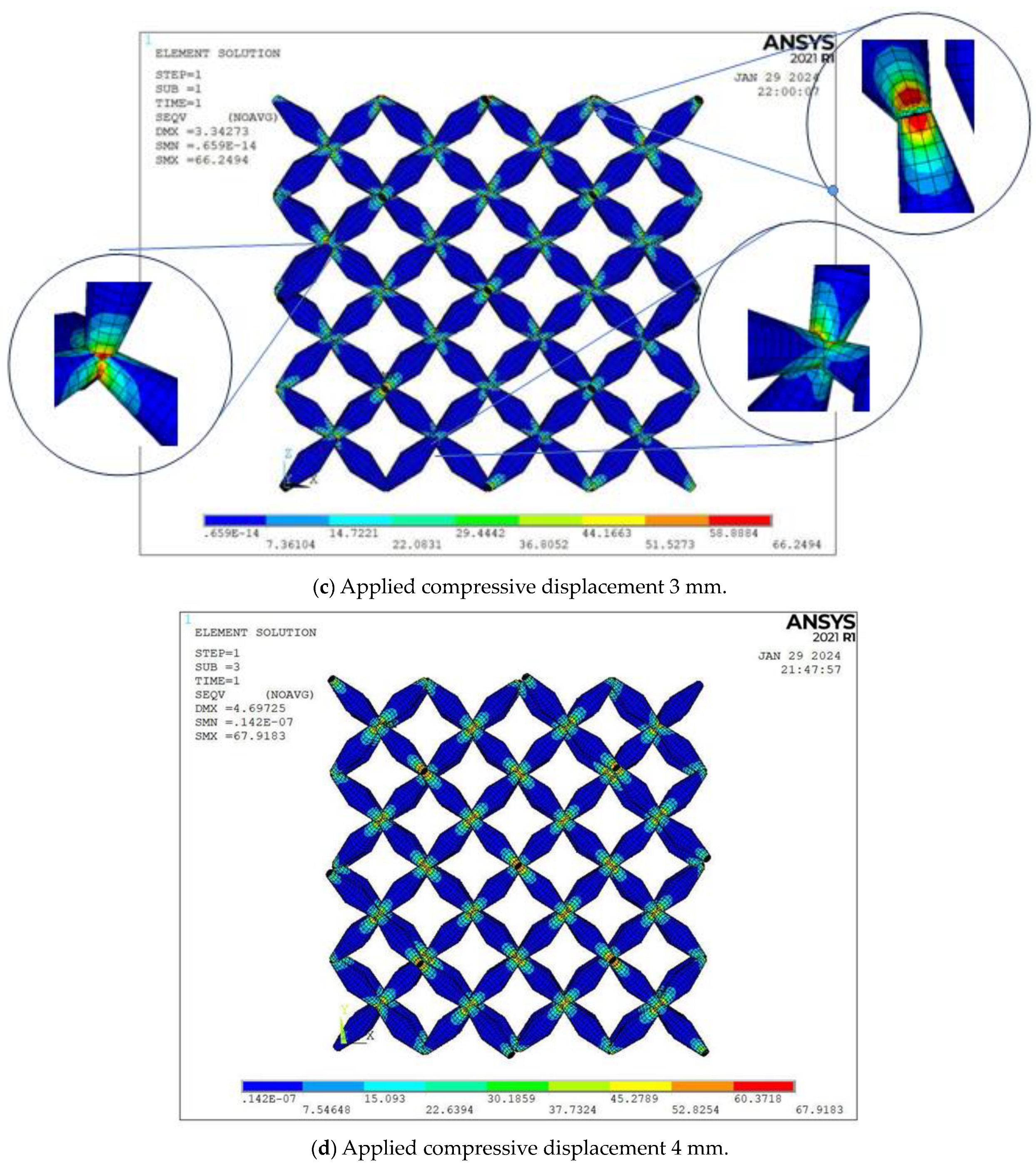
In order to study the stress field under compressive loading, the stresses according to the Von Mises criterion are also plotted, and the results for the first batch of specimens (Table 1) and the different applied displacements δ = 1 ,   2 ,   3 ,   4   mm are presented in Figure 10.
The maximum stresses according to Von Mises criterion from Figure 10 are presented in Table 4. According to the results, the maximum stresses are close to the material’s ultimate tensile strength (Table 2) for the applied displacements δ = 2 ,   3 ,   4   mm . It should be mentioned that the maximum stress for the applied displacement of 2 mm has a higher value than the maximum stress for the applied displacements of 3 mm and 4 mm. This may be explained by the fact that for the cases of 3 mm and 4 mm, the specimen has already failed. The maximum stresses were observed near the beam connections (Figure 10c).
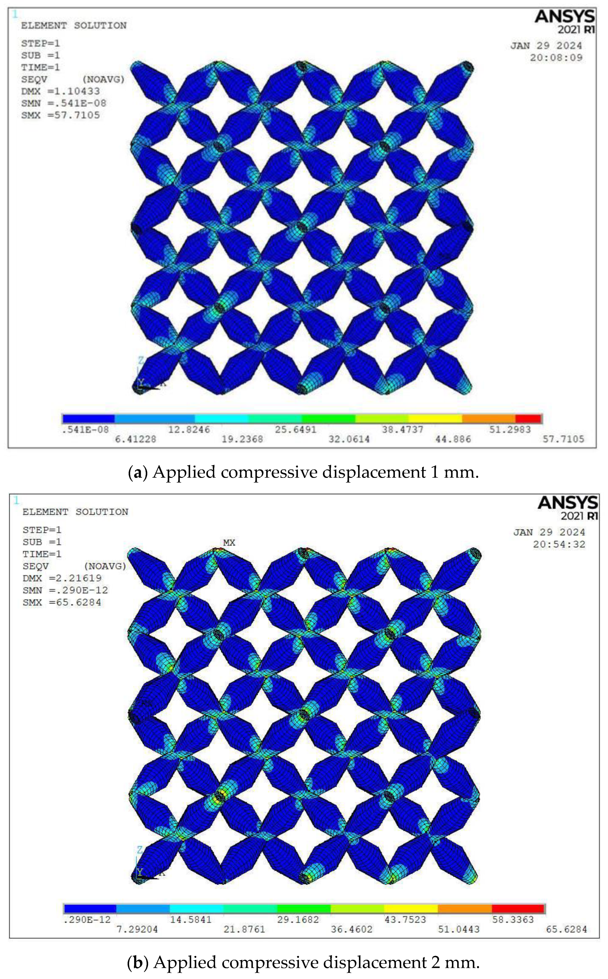
The stress field according to the Von Mises criterion was also studied for the second batch of specimens (Table 1), and the results for the different compressive displacements δ = 1 ,   2 ,   3 ,   4   mm are plotted in Figure 11.
From Figure 11, the maximum stresses according to the Von Mises criterion are presented in Table 5. The maximum stresses are observed to be close to the material’s ultimate tensile strength (Table 2) for the applied compressive displacements δ = 2 , 3 , 4   mm . The maximum Von Mises stress values also appeared at the beam’s connections (Figure 11c).
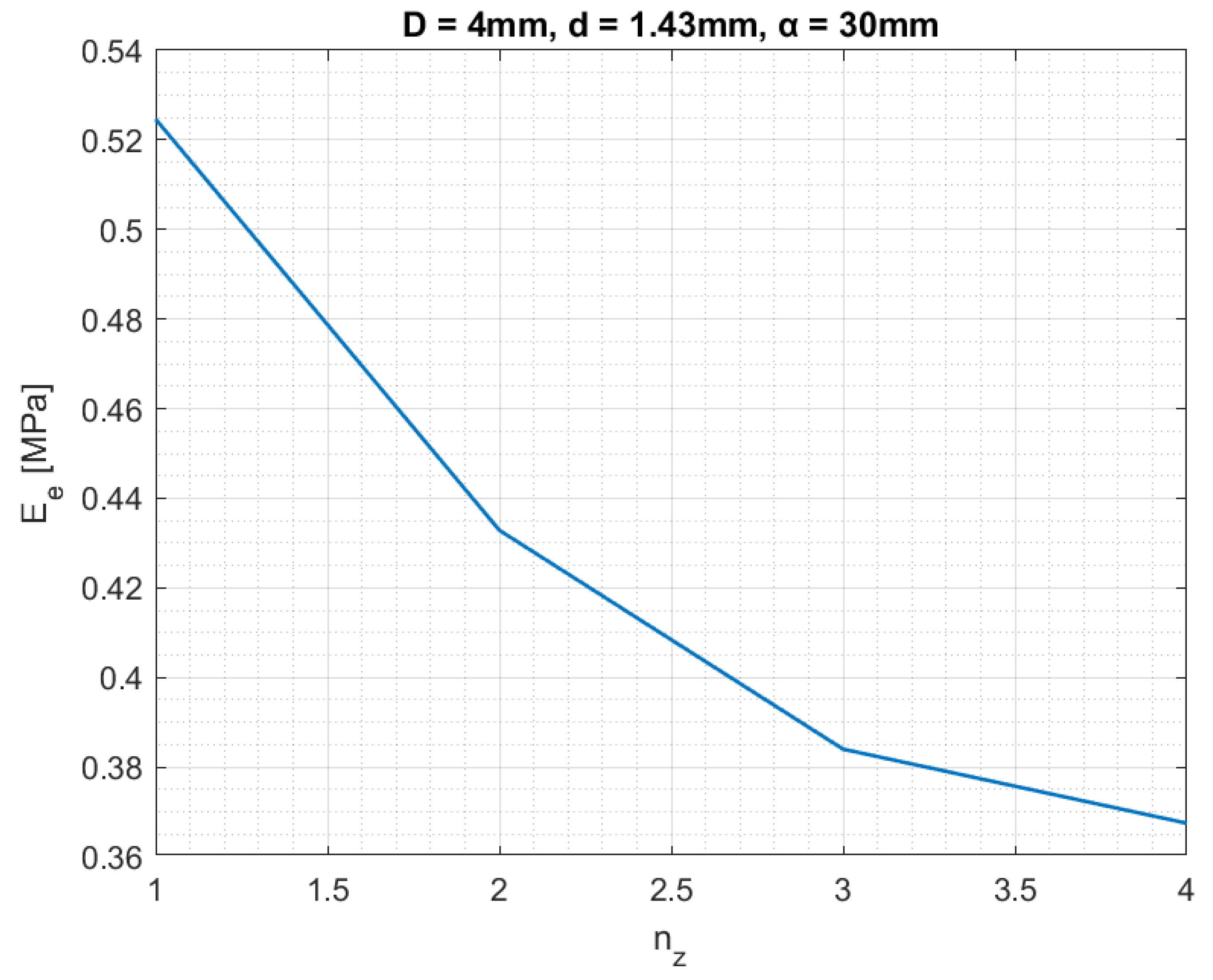
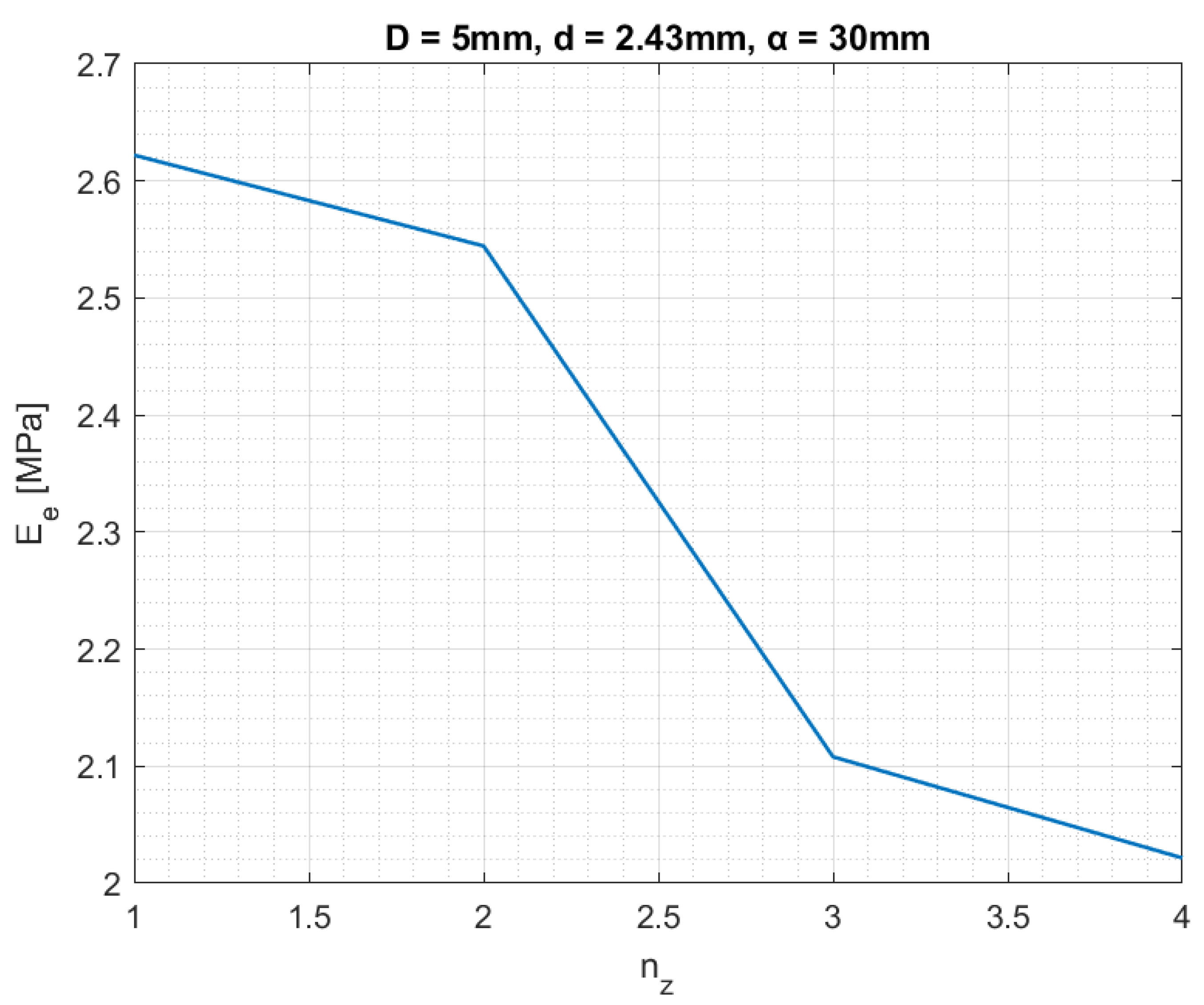
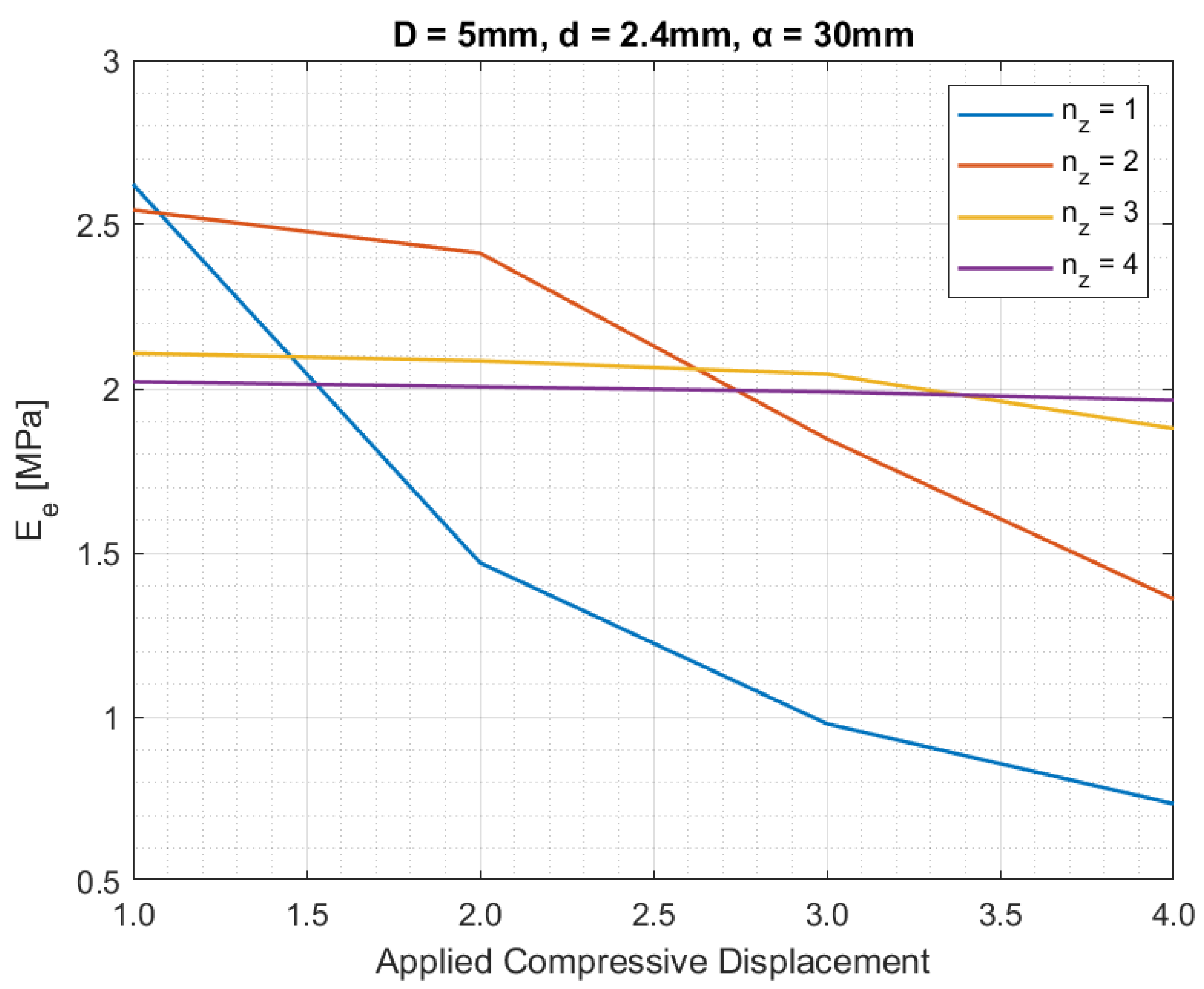
In the sequel, to study the behaviour of pentamode specimens for different heights ( n z ), the effective Young’s modulus is calculated and plotted in Figure 12 and Figure 13 for the first and second batches of specimens, respectively, and for the applied compressive displacement of 1 mm (Table 1).
It is observed that for the first batch of specimens (Figure 12), the pentamode with n z = 1 appeared to have the highest effective Young’s modulus. As the pentamode height n z increases, the effective Young’s modulus decreases in value. In the case of the second batch of specimens, the results for E e are presented in Figure 13.
It is observed (Figure 13) that the results for the second batch of specimens show a different behaviour than those of the first batch (Figure 12). There is an abrupt reduction of the value of E e between n z = 2 and n z = 3 , compared with the reduction of the value of E e in the first batch of specimens (Figure 12). Higher values of E e also appeared in the second batch than in the first batch of specimens.
It should be noted that the reduction of the effective Young’s modulus E e as n z increases (Figure 12 and Figure 13) also appeared in the studies of Amendola et al. [5,6].
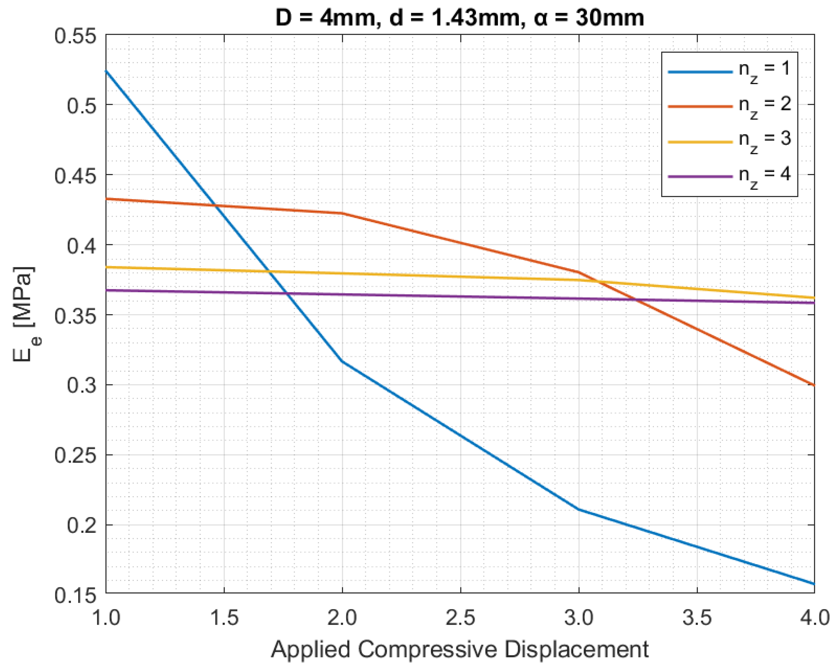
In order to study the behaviour of pentamodes under different applied vertical displacements and heights, the effective Young’s modulus is also calculated under different vertical displacements (Figure 14 and Figure 15) for the first and the second batch of specimens.
For the second batch of specimens, higher values of E e appeared relative to the first batch of specimens. From Figure 14 and Figure 15, in pentamodes with n z = 1 , n z = 2 , discrepancies appeared for the values of E e when different compressive displacements were applied to them. For the cases of n z = 3 , n z = 4 , E e appeared to approach a more constant value as the displacement increased. It is also observed that as the values of the applied compressive displacements increased, the values of the E e generally decreased. But for the cases of n z = 3 , 4 , after the applied compressive displacement of 3 mm, small discrepancies are observed.
Finally, the pentamode bulk modulus will be compared for the results from the analytical equations presented in the studies of Fabbrocino et al. (2016) [6] and Lymperopoulos and Theotokoglou (2022) [22], the effective Young’s modulus from the finite element analyses, and the experimental results. According to Fabbrocino et al. [6], the bulk modulus is given by the following Equation (2),
E F = π E d D 64 3 R 2 ,
whereas according to Lymperopoulos and Theotokoglou [22], the bulk modulus is given by Equation (3),
Ε L , E = 1 2 E d π d + D 64 3 R 2 ,
where E is the Young’s modulus of the material, d is the small diameter, D is the wide diameter and R is the length of the bi-cone beam (Figure 1, Table 2). In the following table (Table 6), the results are presented.
It is observed that for the second batch, the results from the analytical Equation (3), the finite element analyses, and the experimental results almost coincide.

4. Discussion

In our study, two batches of specimens were considered. The first batch of specimens D = 4   mm ,   d = 1.43   mm appeared to have ductile fracture behaviour according to the numerical and experimental analyses, while the second batch of specimens D = 5   mm ,   d = 2.4   mm appeared to have brittle fractures. Fracture is a multifactorial phenomenon that can be influenced by many factors, including environmental factors like temperature and humidity, materials composition, etc. The results of the reaction forces at the bottom nodes of the bi-cone specimens for the different diameters increased as the values of the diameter d increased. It was also observed that the dimension of the d diameter was a significant factor in the final strength of the structure as had also been observed in previous studies [5,6,22]. The prescribed behaviour of the pentamode structures under different specimen dimensions showed great validity. The failure of the pentamode structure from the experimental procedure was observed to take place at the beam connections, which was also verified by the numerical simulations according to the maximum stresses from the Von Mises criterion observed at these points. It is worth noting that other studies [5,23] also found increased values of the specimens at the beam connections. However, these studies were performed only computationally or experimentally but without fracturing the specimens in a laboratory. In our study, analyses of pentamode lattice structures were performed computationally and experimentally for the first time up to the fracture of the specimens. Furthermore, some analytical results were also presented and were compared with numerical and experimental results.
From our experimental analyses, it was observed that the pentamode specimens start to rotate under compression loading at the beginning of fracturing. This behaviour may be explained by their lattice configuration.
The maximum stresses, according to the Von Mises criterion, were observed at the beam connections. In addition, it was observed that the maximum stresses appeared in the second batch of specimens were lower with respect to thoses in the first batch of specimens. This behaviour may be explained by the fact that the second batch of pentamode specimens has a wider beam cross section than that of the first batch, which resulted in reduced Von Misses stresses; consequently, the final strength of the second batch of specimens was higher than that of the first batch. Pentamodes of the first and second batches of specimens for the applied compressive displacements higher than 2 mm, fail according to von Mises criterion.
It was also observed that the value of the effective Young’s modulus E e decrease as the heights n z of the pentamode increase. The prescribed behaviour was similar to that proposed by Amentola et al. [5,6]. It was also observed that the values of E e for the pentamode specimens with heights higher than n z = 2 converge to a rather constant value for both batches of specimens.
It should also be noted that the small diameter d is a significant factor in pentamodes’ overall ultimate strength, rather than D . This was also referred to in the studies of Amendola et al. [5], Fabbrocino et al. [6,7], and Lymperopoulos and Theotokoglou [22].
Furthermore, the effective Young’s modulus [5,6] is a first approach to understanding the pentamode’s lattice structures’ behaviour. The bulk modulus [6,7] represents the elastic stiffness of the lattice structures taking into consideration their periodic nature.

5. Conclusions

In this study, the experimental and numerical results of pentamode lattice structures under compressive loading were compared. Pentamode structures that have been additively manufactured from resin have high bulk strength. This characteristic was not only verified by the numerical simulations but also by the experimental process and the analytical equations. In the experimental results, small discrepancies appeared relative to the numerical results.
In our study andfor the first time, for the pentamode lattice structures of FCC or Diamond type, results are presented from experiments and finite element analyses in the case of compressive loading that took place till the fracture of the specimens, on the contrary to the studies conducted by S.A.M. Ghannadpour et al. [36] and M. Mahmoudi et al. [37] for the Octaset type lattice structures.
Pentamodes represent a wide research area. In this study, our computational analyses used beam elements. In a future study, three-dimensional solid elements may be used to better approach the stress field in beam connections. In addition, according to recent publications [35,38], the force–displacement curves associated with different geometries relative to the weight of the structure may be considered. Finally, beam connections may be studied considering the fillet-type beam connections introduced in the studies of Dallagoa et al. [35] and Iandiorio et al. [38], which may affect the areas of maximum stresses in our study, reducing the stress concentration points and consequently increasing the overall strength of the structure.

Author Contributions

Conceptualization, E.E.T.; methodology, E.E.T. and P.N.L.; validation, P.N.L.; formal analysis, E.E.T. and P.N.L.; investigation, P.N.L. and D.D.; writing—original draft preparation, E.E.T., D.D. and P.N.L.; writing—review and editing, E.E.T., D.D. and P.N.L.; resources, E.E.T., D.K., D.D. and C.M.-K.; supervision, E.E.T. All authors have read and agreed to the published version of the manuscript.

Funding

This research received no external funding.

Data Availability Statement

The original contributions presented in the study are included in the article; further inquiries can be directed to the corresponding author.

Conflicts of Interest

The authors declare no conflicts of interest.

References

  1. Surjadi, J.U.; Gao, L.; Du, H.; Li, X.; Xiong, X.; Fang, N.X.; Lu, Y. Mechanical Metamaterials and Their Engineering Applications. Adv. Eng. Mater. 2019, 21, 1800864. [Google Scholar] [CrossRef]
  2. Barchiesi, E.; Spagnuolo, M.; Placidi, L. Mechanical metamaterials: A state of the art. Math. Mech. Solids 2019, 24, 212–234. [Google Scholar] [CrossRef]
  3. Christensen, R.M. Mechanics of Composite Materials. In Proceedings of the 29. National SAMPE Symposium, Reno, NV, USA, 3 April 1984; pp. 994–1006. [Google Scholar] [CrossRef]
  4. Milton, G.W.; Cherkaev, A.V. Which elasticity tensors are realizable? J. Eng. Mater. Technol. Trans. ASME 1995, 117, 483–493. [Google Scholar] [CrossRef]
  5. Amendola, A.; Smith, C.J.; Goodall, R.; Auricchio, F.; Feo, L.; Benzoni, G.; Fraternali, F. Experimental response of additively manufactured metallic pentamode materials confined between stiffening plates. Compos. Struct. 2016, 142, 254–262. [Google Scholar] [CrossRef]
  6. Fabbrocino, F.; Amendola, A.; Benzoni, G.; Fraternali, F. Seismic application of pentamode lattices. Ing. Sismica 2016, 33, 62–70. [Google Scholar]
  7. Fabbrocino, F.; Amendola, A. Discrete-to-continuum approaches to the mechanics of pentamode bearings. Compos. Struct. 2017, 167, 219–226. [Google Scholar] [CrossRef]
  8. Kadic, M.; Bückmann, T.; Stenger, N.; Thiel, M.; Wegener, M. On the practicability of pentamode mechanical metamaterials. Appl. Phys. Lett. 2012, 100, 191901. [Google Scholar] [CrossRef]
  9. Jia, Z.; Yu, Y.; Hou, S.; Wang, L. Biomimetic architected materials with improved dynamic performance. J. Mech. Phys. Solids 2019, 125, 178–197. [Google Scholar] [CrossRef]
  10. Wang, P.; Yang, F.; Li, P.; Zhang, W.; Lu, G.; Fan, H. Bio-inspired vertex modified lattice with enhanced mechanical properties. Int. J. Mech. Sci. 2023, 244, 108081. [Google Scholar] [CrossRef]
  11. Vyavahare, S.; Mahesh, V.; Mahesh, V.; Harursampath, D. Additively manufactured meta-biomaterials: A state-of-the-art review. Compos. Struct. 2023, 305, 116491. [Google Scholar] [CrossRef]
  12. Zheng, X.; Lee, H.; Weisgraber, T.H.; Shusteff, M.; DeOtte, J.; Duoss, E.B.; Kuntz, J.D.; Biener, M.M.; Ge, Q.; Jackson, J.A.; et al. Ultralight, ultrastiff mechanical metamaterials. Science 2014, 344, 1373–1377. [Google Scholar] [CrossRef]
  13. Needleman, A. Computational mechanics. Appl. Mech. Rev. 1985, 38, 1282–1283. [Google Scholar] [CrossRef]
  14. Gurtner, G.; Durand, M. Stiffest elastic networks. Proc. R. Soc. A Math. Phys. Eng. Sci. 2014, 470, 20130611. [Google Scholar] [CrossRef]
  15. Wang, G.; Jin, L.; Zhang, L.; Xu, Z. Phonon band structures of the three dimensional latticed pentamode metamaterials. AIP Adv. 2017, 7, 025309. [Google Scholar] [CrossRef]
  16. Sapountzakis, E.J.; Syrimi, P.G.; Pantazis, I.A.; Antoniadis, I.A. KDamper concept in seismic isolation of bridges with flexible piers. Eng. Struct. 2017, 153, 525–539. [Google Scholar] [CrossRef]
  17. Liu, K.; Wu, J.; Paulino, G.H.; Qi, H.J. Programmable Deployment of Tensegrity Structures by Stimulus-Responsive Polymers. Sci. Rep. 2017, 7, 3511. [Google Scholar] [CrossRef]
  18. Sapountzaki, O.E.; Kampitsis, A.E.; Lagaros, N.D. Modelling of Inelastic Pentamode-Based Bridge Bearings Using Beam Elements. J. Civ. Eng. Constr. 2023, 12, 126–141. [Google Scholar] [CrossRef]
  19. Craster, R.; Guenneau, S.; Kadic, M.; Wegener, M. Mechanical metamaterials. Rep. Prog. Phys. 2023, 86, 094501. [Google Scholar] [CrossRef]
  20. Lymperopoulos, P.N.; Theotokoglou, E.E.; Antoniadis, I.A. Computational analysis of metamaterials—An initial study. Procedia Struct. Integr. 2020, 25, 172–179. [Google Scholar] [CrossRef]
  21. Lymperopoulos, P.N.; Theotokoglou, E.E. Computational analysis of pentamode metamaterials for antiseismic design. Procedia Struct. Integr. 2020, 26, 263–268. [Google Scholar] [CrossRef]
  22. Lymperopoulos, P.N.; Theotokoglou, E.E. Numerical Investigation of Pentamode Mechanical Metamaterials. Wseas Trans. Appl. Theor. Mech. 2022, 17, 47–55. [Google Scholar] [CrossRef]
  23. Guo, D.; Jiang, S.; Zhou, Y.; Zhang, L.; Li, K.; Song, B.; Huang, Y. Ultrahigh compression-shear ratio of sandwich pentamode metamaterials. Compos. Struct. 2023, 322, 117331. [Google Scholar] [CrossRef]
  24. Zhang, Z. A review on additive manufacturing of wave controlling metamaterial. Int. J. Adv. Manuf. Technol. 2022, 124, 647–680. [Google Scholar] [CrossRef]
  25. Schittny, R.; Bückmann, T.; Kadic, M.; Wegener, M. Elastic measurements on macroscopic three-dimensional pentamode metamaterials. Appl. Phys. Lett. 2013, 103, 231905. [Google Scholar] [CrossRef]
  26. Zadpoor, A.A. Mechanical performance of additively manufactured meta-biomaterials. Acta Biomater. 2019, 85, 41–59. [Google Scholar] [CrossRef]
  27. Janbaz, S.; Bobbert, F.S.L.; Mirzaali, M.J.; Zadpoor, A.A. Ultra-programmable buckling-driven soft cellular mechanisms. Mater. Horiz. 2019, 6, 1138–1147. [Google Scholar] [CrossRef]
  28. Hedayati, R.; Amin Yavari, S.; Zadpoor, A.A. Fatigue crack propagation in additively manufactured porous biomaterials. Mater. Sci. Eng. C 2017, 76, 457–463. [Google Scholar] [CrossRef]
  29. Hu, Z.; Wei, Z.; Wang, K.; Chen, Y.; Zhu, R.; Huang, G.; Hu, G. Engineering zero modes in transformable mechanical metamaterials. Nat. Commun. 2023, 14, 1266. [Google Scholar] [CrossRef]
  30. Türk, D.A.; Brenni, F.; Zogg, M.; Meboldt, M. Mechanical characterization of 3D printed polymers for fiber reinforced polymers processing. Mater. Des. 2017, 118, 256–265. [Google Scholar] [CrossRef]
  31. Wu, S.; Luo, Z.; Li, Z.; Liu, S.; Zhang, L.C. Topological design of pentamode metamaterials with additive manufacturing. Comput. Methods Appl. Mech. Eng. 2021, 377, 113708. [Google Scholar] [CrossRef]
  32. Kladovasilakis, N.; Tsongas, K.; Karalekas, D.; Tzetzis, D. Architected Materials for Additive Manufacturing: A Comprehensive Review. Materials 2022, 15, 5919. [Google Scholar] [CrossRef] [PubMed]
  33. Hu, K.; Zhang, L.; Zhang, Y.; Song, B.; Wen, S.; Liu, Q.; Shi, Y. Electrochemical Corrosion Behavior and Mechanical Response of Selective Laser Melted Porous Metallic Biomaterials. Acta Metall. Sin. Engl. Lett. 2023, 36, 1235–1246. [Google Scholar] [CrossRef]
  34. Fraternali, F.; Amendola, A. Mechanical modeling of innovative metamaterials alternating pentamode lattices and confinement plates. J. Mech. Phys. Solids 2017, 99, 259–271. [Google Scholar] [CrossRef]
  35. Dallagoa, M.; Raghavendraa, S.; Luchinb, V.; Zappinib, G.; Pasinic, D.; Benedettia, M. The role of node fillet, unit-cell size and strut orientation on the fatigue strength of Ti-6Al-4V lattice materials additively manufactured via laser powder bed fusion. Int. J. Fatigue 2021, 142, 105946. [Google Scholar] [CrossRef]
  36. Ghannadpour, S.A.M.; Mahmoudi, M.; Nedjad, K.H. Structural behavior of 3D-printed sandwich beams with strut-based lattice core: Experimental and numerical study. Compos. Struct. 2022, 281, 115113. [Google Scholar] [CrossRef]
  37. Mahmoudi, M.; Ghannadpour, S.A.M.; Nedjad, K.H. Functionally graded multi-morphology lattice structures as an optimized sandwich core via digital light processing additive manufacturing. Mater. Des. 2024, 238, 112710. [Google Scholar] [CrossRef]
  38. Iandiorio, C.; Mattei, G.; Marotta, E.; Costanza, G.; Tata, M.E.; Salvini, P. The Beneficial Effect of a TPMS-Based Fillet Shape on the Mechanical Strength of Metal Cubic Lattice Structures. Materials 2024, 17, 1553. [Google Scholar] [CrossRef]
  39. FormLabs. Standard Materials for High-Resolution Rapid Prototyping; FormLabs: Somerville, MA, USA, 2017; pp. 1–3. [Google Scholar]
  40. PTC. Creo Parametric 9 Student Edition, PTC CREO; PTC: Boston, MA, USA, 2022. [Google Scholar]
  41. ANSYS. ANSYS Mechanical User’ s Guide; Release 19.0; Ansys Inc.: Canonsburg, PA, USA, 2021. [Google Scholar]
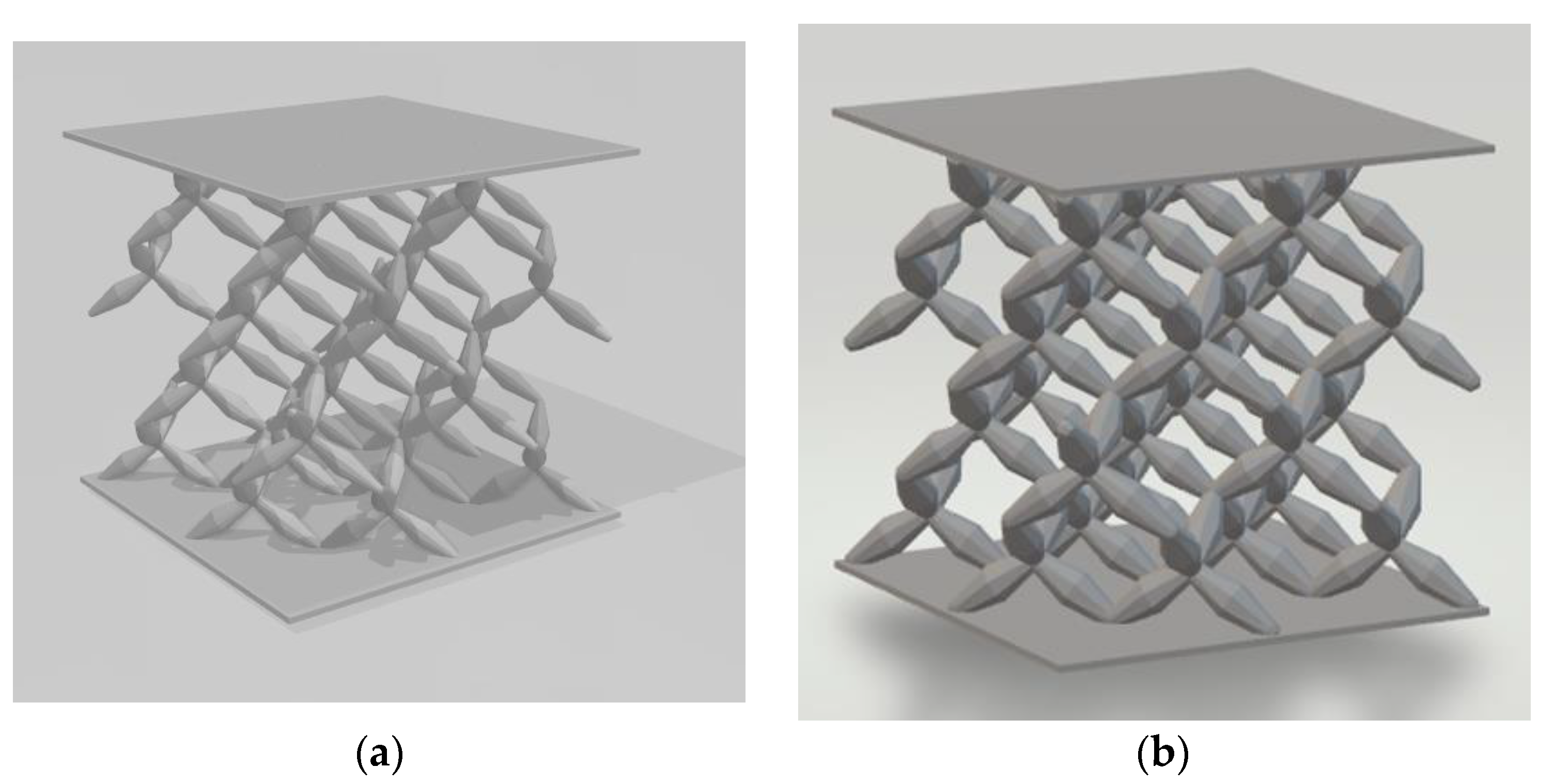
Figure 1. Pentamode unit cell [5,6,22,34].
Infrastructures 09 00172 g001
Figure 2. Pentamode structure: (a) first batch of specimens; (b) second batch of specimens.
Infrastructures 09 00172 g002
Figure 3. 3D printer Form 3+.
Infrastructures 09 00172 g003
Figure 4. Stress–strain curve for Clear V4 [39].
Infrastructures 09 00172 g004
Figure 5. Pentamode experimental setup: (a) pentamode between two grips without loading, (b) pentamode between two grips under pressure loading, and (c) pentamode failure.
Infrastructures 09 00172 g005
Figure 6. Convergence of the results.
Infrastructures 09 00172 g006
Figure 7. Numerical and experimental results for the first batch of specimens.
Infrastructures 09 00172 g007
Figure 8. Numerical and experimental results for the second batch of specimens.
Infrastructures 09 00172 g008
Figure 9. Numerical results for different diameters d.
Infrastructures 09 00172 g009
Figure 10. Stress field according to Von Mises criterion in pentamode structures (first batch of specimens) for different applied displacements (a) 1 mm, (b) 2 mm, (c) 3 mm, and (d) 4 mm.
Infrastructures 09 00172 g010aInfrastructures 09 00172 g010b
Figure 11. Stress field according to Von Mises criterion in pentamode structures (second batch of specimens) for different applied displacements (a) 1 mm, (b) 2 mm, (c) 3 mm, and (d) 4 mm.
Infrastructures 09 00172 g011aInfrastructures 09 00172 g011b
Figure 12. Pentamode effective Young’s modulus for the different heights n z and for the applied compressive displacement of 1 mm in the case of the first batch of specimens (Table 1).
Infrastructures 09 00172 g012
Figure 13. Pentamode effective Young’s modulus for the different heights n z and for the applied compressive displacement of 1 mm in the case of the second batch of specimens (Table 1).
Infrastructures 09 00172 g013
Figure 14. Pentamode effective Young’s modulus for different compressive displacements and for different heights for the first batch of specimens.
Infrastructures 09 00172 g014
Figure 15. Pentamode effective Young’s modulus for different compressive displacements and for different heights for the second batch of specimens.
Infrastructures 09 00172 g015
Table 1. Pentamode dimensions.
Pentamode BatchD [mm]d [mm]α [mm]
Batch 141.4330
Batch 252.430
Table 2. Material properties according to the “Standard Test Method for Properties of Plastics ASTM D638-10” [39].
Ultimate Tensile Strength [MPa]65
Tensile Modulus [GPa]2.8
Elongation at Failure [%]6.2
Table 3. Effective Young’s modulus for different d diameters, in the case of D = 4 mm and α = 30 mm.
Diameter [mm]Effective Young Modulus [MPa]
d = 1.430.4394
d = 1.60.6057
d = 1.80.8457
d = 2.01.1365
d = 2.21.4805
d = 2.41.8796
Table 4. Maximum stresses according to Von Mises criterion appearing in the first batch of specimens for different applied compressive displacements.
Displacement [mm]Maximum Von Mises Stresses [MPa]
144.686
268.3849
366.2494
467.9183
Table 5. Maximum Von Mises stresses appearing in the second batch of the pentamode structure for different applied compressive displacements.
Displacement [mm]Maximum Von Mises Stresses [MPa]
157.7105
265.6284
366.2525
465.0583
Table 6. Comparison of modulus among the analytical equations [6,22], and the effective Young’s modulus from the finite element analyses and the experiments.
Equation (2) [MPa]Equation (3) [MPa]Finite Element Analyses [MPa]Experimental Results [MPa]
1st Batch2.631.771.871.15
2nd Batch5.644.1854.16
Disclaimer/Publisher’s Note: The statements, opinions and data contained in all publications are solely those of the individual author(s) and contributor(s) and not of MDPI and/or the editor(s). MDPI and/or the editor(s) disclaim responsibility for any injury to people or property resulting from any ideas, methods, instructions or products referred to in the content.