Article

The Efficiency of the Benefits of Tire-Derived Aggregate Backfill for Buried Concrete Pipes Beneath Paved and Unpaved Roads

by
Saif Alzabeebee
1,
Safaa Manfi Alshibany
1,
Suraparb Keawsawasvong
2 and
Davide Forcellini
3,*
1
Department of Roads and Transport Engineering, University of Al-Qadisiyah, Al-Diwaniyah 58002, Iraq
2
Research Unit in Sciences and Innovative Technologies for Civil Engineering Infrastructures, Department of Civil Engineering, Thammasat School of Engineering, Thammasat University, Pathumthani 12120, Thailand
3
Faculty of Civil and Environmental Engineering, University of San Marino, Via Consiglio dei Sessanta, 99, 47899 Serravalle, San Marino
*
Author to whom correspondence should be addressed.
Infrastructures 2023, 8(7), 107; https://doi.org/10.3390/infrastructures8070107
Submission received: 18 May 2023 / Revised: 14 June 2023 / Accepted: 21 June 2023 / Published: 25 June 2023

Abstract

:
Tire-derived aggregate (TDA) has been proposed in recent studies to be considered as part of backfill soil to reduce stress and strain developed in buried pipes. However, little attention is paid to checking the influence of TDA on the behavior of concrete pipes buried under trafficked roads. This research studies this topic using a verified numerical model that considers the three-dimensional nature of traffic load effects. Different road sections were considered in the analyses to cover the effect of the presence of the pavement layer and the effect of the thickness of the base and subbase materials. The results revealed that the presence of TDA decreases the bending moment induced in the pipe wall. However, the TDA performance was found to be remarkably influenced by burial depth, and it increases as the burial depth decreases. Furthermore, the TDA influence for pipes with outer diameters of 1.49 m and 2.89 m is much lower than that of 0.41 m and 0.79 m. Importantly, it was found that the highest reduction in the bending moment was achieved for the 1.0 m burial depth. The results of this research provide insight into the performance of TDA and, thus, will help practitioners make a decision regarding the use of TDA in the routine design of buried concrete pipes.

1. Introduction

Several countries prevent the storing of used tires, encourage recycling of these tires, and use them in useful and sustainable applications. One of these applications is to shred the tires to develop so-called tire-derived aggregate (TDA). The particle size of this TDA is usually in the range of 12–305 mm. This technique was developed to be used in civil engineering applications, such as the ASTM D6270 [1], which presented guidelines for the effective usage of TDA in many applications. TDA has been used successfully in culverts and buried pipe applications due to its compressibility and light weight to reduce the soil pressure applied to these structures by placing a layer of a compressible material (TDA) above the pipe to induce a positive arching mechanism [2,3,4,5]. Soil over buried pipes settles further than surrounding soils, resulting in positive arching action. Hence, the shear stresses generated on the side of the backfill result in the earth pressure over the pipe being lower than the total stress applied due to the soil weight above the pipe. This process is called “induced trench installation” [4,6]. In this regard, Meguid and Youssef [3] implemented a laboratory test to inspect the efficiency of TDA in reducing the wall stresses of a 150 mm PVC pipe subjected to embankment fill (soil) loads. TDA reduced the stresses in the pipe crown, according to the study. Ni et al. [7] investigated the advantages of using a material with low stiffness over a concrete pipe buried under an embankment. Mahgoub and El Naggar [4] conducted tests to check the effect of TDA on the response of an existing pipe found below a raft foundation. In a study by Mahgoub and El Naggar [5], a decrease in the stresses developed in the pipe wall as a result of the presence of TDA is described, and in Mahgoub and El Naggar [8], the same authors carried out laboratory and simulation studies to study the influence of TDA on the structural response of steel plate culverts. It was found that TDA increased positive soil arching. Recently, Alzabeebee et al. [9] studied the effect of TDA on the response of buried concrete pipes under the influence of embankment load using three-dimensional finite element analysis. They considered different diameters and backfill heights. In addition, Alzabeebee et al. [9] considered the effect of TDA on concrete pipes subjected to seismic shaking using two-dimensional finite element analysis. A case study of a buried pipe with a diameter of 80 cm and a burial depth of 2.0 m was considered in the analysis. It was found that TDA reduced 33% of the maximum bending moment for the static condition and 22–38% for the seismic condition. Karaman et al. [10] and Ni et al. [11,12] examined the effect of TDA in backfill on the strains and stresses generated in a buried pipe during strike–slip fault movement. Apart from the deterministic behavior of TDA, there are also studies about the stochastic variability of the TDA material, such as Strenk et al. [13]. These extend the works about the uncertainty of quantification in cohesionless [14] and cohesive [15] soils. In addition, some recent studies focused on the development of recycled aggregate to be used as backfill for pipes in trenches [16,17].
In summary, as established upon this review, the influence of TDA on the structural response of buried concrete pipes is still not understood. In addition, there are no study reports on the performance of TDA for different pipe diameters and burial depths. Therefore, this study aimed to advance the knowledge on this topic using the following objectives:
(1)
To develop a three-dimensional finite element (3D FE) model that is able to accurately calculate the pipe wall bending moment.
(2)
To examine the efficiency of TDA for different pipe diameters and burial depths.
(3)
To compare the efficiency of TDA for both paved and unpaved roads.

2. Statement of the Problem

As discussed in the previous section, this research studied the effect of TDA on the behavior of concrete pipes buried under paved and unpaved trafficked roads by concentrating on the structural response of a concrete pipe buried under a road. The heavy axles of two H25 trucks were utilized in the analysis to simulate a stringent scenario similar to a study by [18] by considering the critical loading condition. In addition, different road sections were considered (highway, public road sections, and unpaved road). Details of these sections are shown in Figure 1a–c.
A reference case of a conventional trench (CB) was used. Sandy soil compacted to a compaction degree of 90% as per the standard Proctor test (referred to as SW90) was considered as the soil supporting the pipe for the CB case. This condition aimed to replicate AASHTO Type 2 installation conditions [19], as illustrated in Figure 2a. AASHTO Type 2 involves the use of compacted soil in the bedding and pipe haunch to ensure uniform distribution of soil pressure in the haunch and bedding area. The other trench was the TDA trench, which is explained in Figure 2b. As is clear from the figure, the considered TDA layer had a thickness of 150 mm and was placed above the crown of the pipe. These cases were simulated using the 3D FE method to consider the three-dimensional nature of the traffic load effect.

3. Methodology

This section presents the methodology followed in the paper, considering several steps: definition of the constitutive models and the description and validation of the numerical models.

3.1. Constitutive Models

The hardening soil constitutive model (HSM) was utilized to represent the stress–strain behavior of TDA and SW90. This constitutive model derivation allows the consideration of the effective stress, deviatoric stress, and confining pressure on the stiffness of the soil [20]. The robustness and suitability of the HSM model for this problem have been verified by [4]. In the HSM, soil stiffness is represented by using three individual parameters: the secant reference modulus (E50ref), the tangent oedometer reference stiffness (Eoedref), and the unloading–reloading reference stiffness (Eurref). All the previously mentioned reference stiffness parameters are computed with the reference stress Pref. In addition, the HSM uses the Mohr–Coulomb failure criteria to define the shear failure, employing the parameters of the shear strength (ϕ′ and c′). In addition, it uses the dilatancy angle (ψ′), which is used to define the irreversible change in volume. Furthermore, υur simulates the unloading–reloading Poisson’s ratio in the HSM. The stiffness dependency on the level of stress is defined in the HSM using the power factor ( m ), and the Rf parameter is used to define the ratio of failure that controls the level of strain at failure. Finally, the horizontal stress of the soil is calculated using the coefficient of lateral soil stress (Konc) in the HSM. On the other hand, a linear elastic material model was assigned for the asphalt surface and the pipe; this model requires only two input parameters: the modulus of elasticity (E) and Poisson’s ratio (υ). Furthermore, the base course, subbase course, and subgrade were all modeled using the Mohr–Coulomb model, which needs five input parameters: the modulus of elasticity (E), Poisson’s ratio (υ), the angle of internal friction (ϕ′), cohesion (c′), and the dilatancy angle (ψ′). The parameters employed in the simulation were taken from different references [8,21,22,23,24,25]. Table 1 and Table 2 present the utilized parameters. It is important to state that these parameters were also utilized by authors in previous studies [9,26,27].

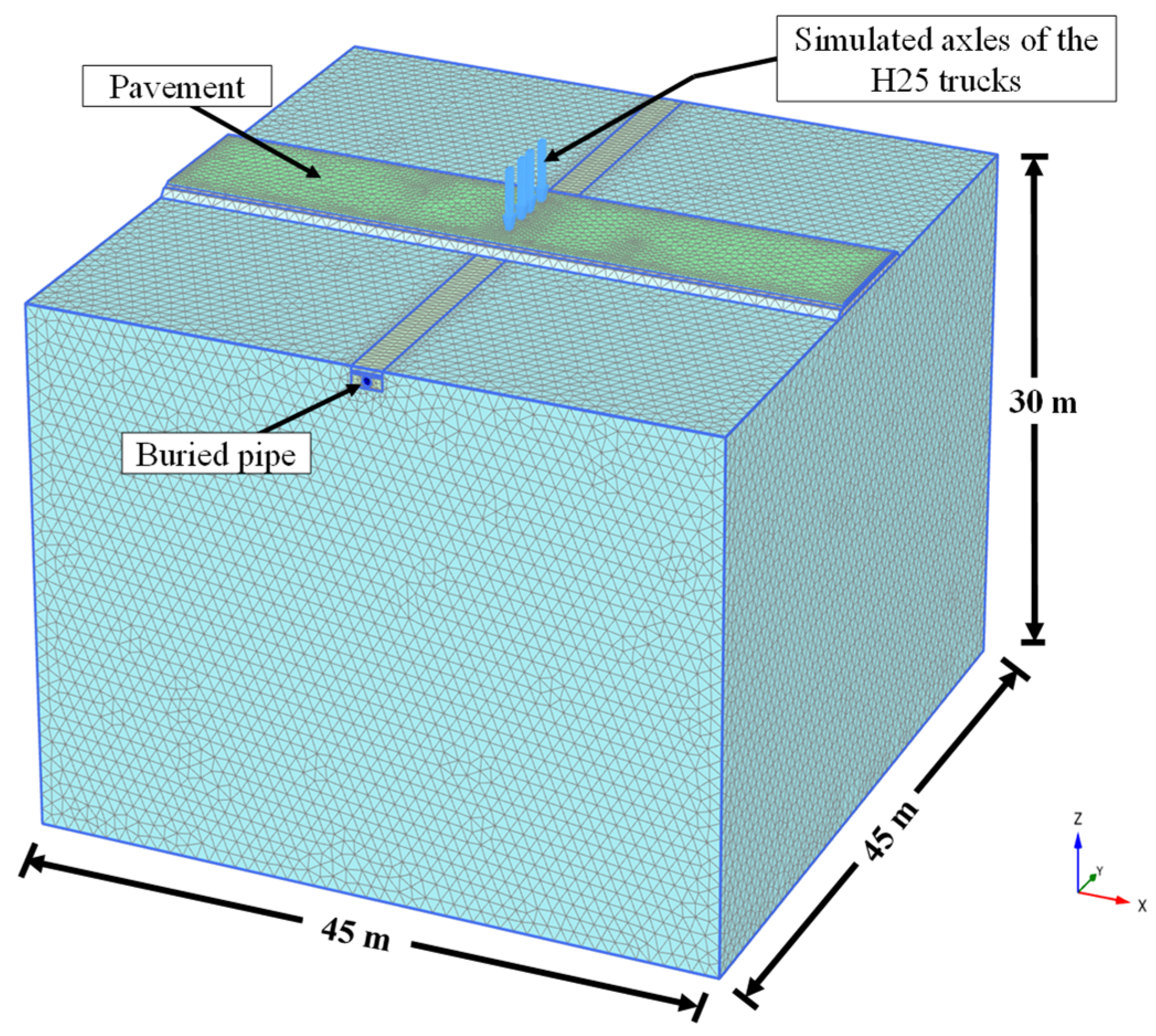
3.2. The Numerical Model

Figure 3 shows the model developed in this research, which was developed using Plaxis 3D. The model length, width, and height were considered equal to 45 m, 45 m, and 30 m, respectively. These dimensions were decided upon based on a sensitivity study. The soil and pavement layers were simulated using solid elements. The mesh was decided upon with the aid of an analysis of a mesh quality assessment. The mesh quality assessment involved checking the effect of mesh density on the results of the finite element analysis by using different densities of mesh (coarse, fine, very fine, and very fine mesh with extra local refinements) and seeing the sensitivity of the results to the mesh density. This stage helped the authors decide the mesh density, which does not influence the results, even if it has been further refined. However, the results of this sensitivity study are not presented in the paper for the sake of brevity. In addition, standard boundary conditions were used in the analysis, similar to previous studies [28,29,30,31,32,33,34]. The soil–pipe interface was considered using Plaxis interface elements, where an interaction factor of 0.7 was utilized, similar to previous studies on the modeling of buried concrete pipes (e.g., [9]). The bedding thicknesses were considered to be 10 cm for pipes with diameters of 30–120 cm and 15 cm for the 240 cm diameter pipe. Static load was used in the analysis, as this type of load produces higher deformation compared to moving loads [35,36,37]. To allow for a practical simulation, staged construction was carried out in the analysis to enable the replication of field conditions, as follows:
-
The first step involved modeling the in situ (geostatic stress) stresses of the soil. The vertical stresses in this step were calculated using the unit weight and the depth of the soil, while the horizontal stresses were calculated using the Jackey equation.
-
The second step simulated the excavation of the trench.
-
The third step simulated pipe installation.
-
The fourth step simulated the backfilling of the soil.
-
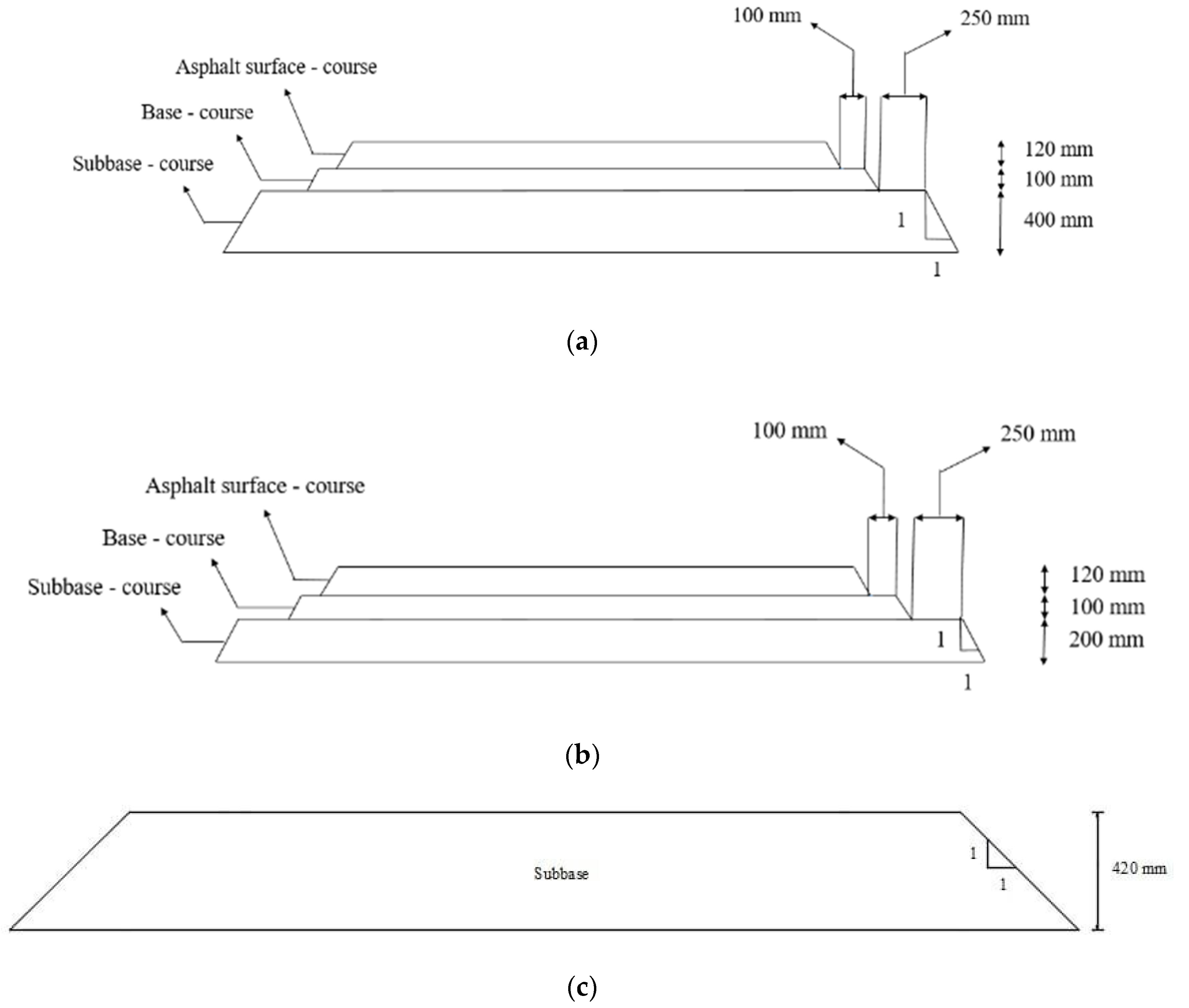
The fifth step involved the construction of the road embankment and surface layer.
-
The sixth step involved the application of the rear axle loads of the two H25 trucks.

3.3. Validation of the FE Model

The validation study involved replicating a laboratory experiment carried out by MacDougall [38] to verify the accuracy of the methodology of the study. The experiment by MacDougall [38] involved an examination of the behavior of concrete pipes under a surface load of 100 kN. The inner diameter of the concrete pipe used in the MacDougall [38] test was 60 cm, and its wall thickness was 9.4 cm. The pipe was made from concrete with a compressive strength of 66 MPa. In particular, MacDougall [38] used well-compacted, coarse-grained soil in her experiment, which corresponded to AASHTO Type 2 installation conditions. In addition, the same soil was used above the pipe crown as a backfill soil. This test was simulated in this study using previously explained methodology to illustrate the robustness of the adopted methodology. The well-compacted soil was modeled using SW90 properties. Figure 4 shows a comparison of the obtained and measured circumferential bending moments, where it is evident that the developed model provides results that are in very good agreement with the laboratory measurements, where the percentage difference between the present study and the study of MacDougall [38] ranges between 1 and 10%.

4. Parametric Study

To investigate how TDA material can reduce the bending moment in buried concrete pipes (i.e., the efficiency of TDA), a thorough examination was conducted, which involved varying the road section, burial depth, and pipe diameter parameters. Four standard pipe diameters with different wall thicknesses were used in the analyses in an effort to gain greater insight into the efficiency of TDA. Table 3 displays the considered diameters. These numbers were taken from previous studies [19]. The findings obtained from this parametric study are discussed in the following subsections.

4.1. Effect of TDA on the Distribution of Bending Moment

By analyzing the bending moment developed in the pipe wall using both conventional backfill (CB) and TDA, this section investigated how the distribution of bending moment is impacted by the presence of TDA. The case of a buried pipe with an inner diameter (D) of 120 cm and a burial depth of 1.0 m was selected for this task. The impact of TDA on the distribution of the bending moment in the pipe wall is depicted for three scenarios (a highway section, a public road, and an unpaved road) in Figure 5a–c, respectively. Although TDA decreases the bending moment, it does not alter the correlation between the bending moment and the angle from the pipe crown, as is apparent from the results presented in the figures. Furthermore, comparing the results of Figure 5a–c shows that the highest bending moment values were recorded for the case of the unpaved road. This is expected, as the presence of an asphalt surface layer reduces the soil pressure developed due to the traffic load. Moreover, the bending moment induced in the pipe wall is marginally greater for the public road compared to the highway section. This marginal increase in the bending moment is attributed to the higher thickness of the asphalt layer in the highway section, and this layer contributed to decreasing the soil pressure applied to the pipe. As a result, it is possible to conclude that the case of the unpaved road represents a more stringent scenario than the paved roads.

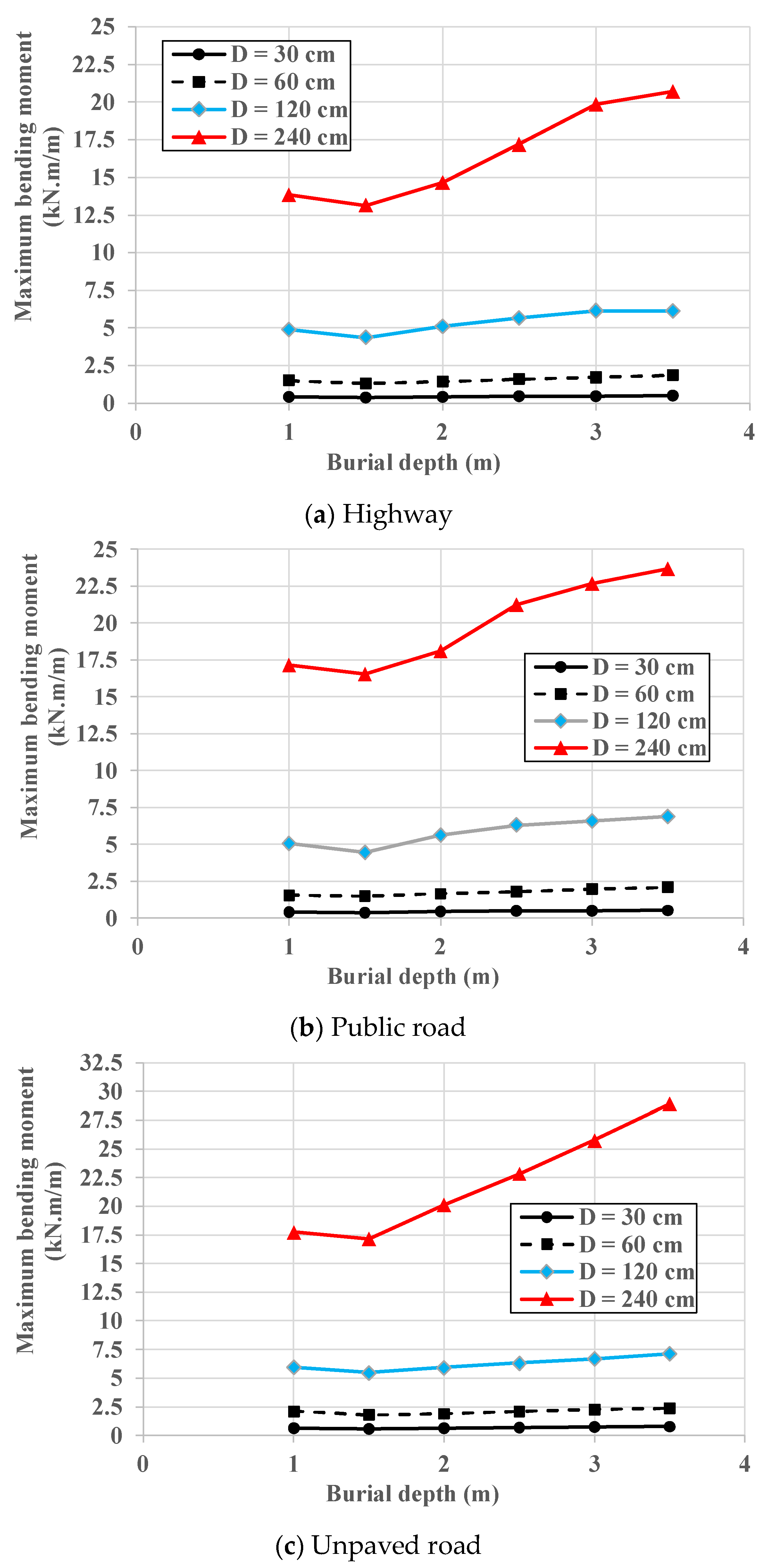
4.2. Effect of Burial Depth on the Efficiency of TDA

The impact of burial depth on the maximum bending moment in the pipe wall is illustrated in Figure 6a–c for the CB and TDA configurations for the highway, public road, and unpaved road, respectively. The results presented in Figure 6a–c are for a buried pipe with an inner diameter of 120 cm. It can be noticed from the figures that, for the CB configuration, the maximum bending moment decreases as the backfill height increases from 1.0 m to 1.5 m and then non-linearly increases when the backfill height becomes more than 1.5 m. This behavior is due to the combined influence of the burial depth and the traffic load and the reduction in the traffic load effect as the burial depth rises, which makes the soil weight control the behavior. In addition, it is clear from the figures that the TDA configuration follows the same trend as the CB configuration; however, the induced maximum bending moment for the TDA configuration is lower than that of the CB configuration. This behavior can be attributed to positive soil arching, which occurs as a result of the TDA layer above the pipe crown and leads to a decrease in the soil pressure exerted on the pipe.
For each scenario, the bending moment ratio between the CB and TDA configurations is determined and displayed in Figure 7a–c, representing the highway section, public road, and unpaved road, respectively. This was performed to measure the reduction in the maximum bending moment in terms of percentage. The figures clearly indicate that as the burial depth rises, the beneficial impact of TDA lessens. This is demonstrated by a decrease in the bending moment ratio with increasing burial depth for all three scenarios. As per the results, positive arching was observed to decline with an increase in burial depth across all the road sections studied in this research. Furthermore, Figure 7a–c indicate that the bending moment ratio remains relatively constant beyond a certain burial depth. This depth was determined to be 2.0 m for the highway section and the unpaved road and 2.5 m for the public road. Such behavior is associated with the arching mechanism, as the arching factor tends to stabilize with an increase in burial depth. The issue is further complicated by the interplay between burial depth and traffic loads.
Figure 7a–c further demonstrates that the maximum reduction in bending moment is achieved at a burial depth of 1.0 m, where the percentage reductions in the maximum bending moment are 35%, 21%, and 19% for the highway section, public road, and unpaved road, respectively. However, it is important to note that there is no universal conclusion that can be drawn regarding the variation in percentage reduction observed for different road sections. This is because of the complex behavior of soil arching, which is sensitive to factors such as the presence and thickness of the pavement layer, burial depth, and the impact of traffic load on the plastic (failure) state of the soil, particularly in the case of unpaved roads.

4.3. Effect of Pipe Diameter on the Efficiency of TDA

This section investigated the impact of pipe diameter on the effectiveness of TDA by simulating the diameters listed in Table 3 for the CB and TDA configurations. The maximum bending moment for each case was then calculated. Figure 8a–c demonstrate the relationship between the maximum bending moment and burial depth for the CB configuration on the highway section, public road, and unpaved road, respectively. It is evident from the figures that the maximum bending moment increases considerably with increasing pipe diameter. This is because of the larger perimeter of the pipe shoulders, resulting in increased soil weight on the shoulders. Additionally, the maximum bending moment decreases as the burial depth increases from 1.0 to 1.5 m and then increases non-linearly for all road sections. This response could be justified by the combined influence of both the soil weight applied on the pipe and the traffic loads. Comparing the results of the highway, public road, and unpaved road shows a higher maximum bending moment induced in the pipe wall for the scenario of the unpaved road. This is attributed to the higher soil pressure reaching the pipe in the case of the unpaved road due to the absence of the stiff surface layer, which contributes greatly to reducing the traffic load effect.
Figure 9a–c depicts the influence of pipe diameter on the maximum bending moment ratio for the three road sections. The results of the ratios for diameters of 30 cm and 60 cm are very close for every road section and indicate that TDA is efficient for concrete pipes with relatively small diameters. However, the efficiency of TDA reduces for a diameter of 120 cm, where the ratio is lower than that recorded for the diameters of 30 cm and 60 cm and for every road section. Moreover, for pipes with a diameter of 240 cm, the ratio is the lowest for every road section, ranging between 6% and 14%. This decrease in efficiency may be attributed to the TDA layer’s low thickness; therefore, further research should investigate the effect of the TDA layer’s thickness. Generally, the results indicate that TDA’s efficiency in reducing the concrete pipe wall bending moment decreases as the inner diameter increases to 120 cm. Moreover, for pipes with a diameter of 240 cm, TDA’s efficiency becomes insignificant, as the percentage reduction is less than 10% for all simulated burial depths of the public and unpaved roads and for a burial depth range of 1.5–3.5 m for the highway section.

5. Summary and Conclusions

The present study investigated the effectiveness of TDA under various scenarios through a validated three-dimensional finite element model. The analysis incorporated diverse factors, such as distinct road conditions, pipe diameters, and backfill depths. The following could be stated based on the findings from this study:
1-
The application of TDA results in a reduction in the bending moment experienced by the wall of a concrete pipe when it is buried and subjected to both soil and traffic loads. However, TDA does not affect the trend of the bending moment distribution in the pipe wall.
2-
The maximum reduction in the bending moment due to the presence of TDA happens at a burial depth of 1.0 m. In addition, the beneficial effect of TDA reduces as the burial depth rises and stabilizes. This is due to the reduction in positive arching as the depth of burial increases.
3-
Generally, the efficiency of TDA is higher for pipes with inner diameters of 30 cm and 60 cm and reduces as the inner diameter of the pipe increases to 120 cm. In addition, the TDA effect becomes very minor for a pipe diameter of 240 cm, and the percentage reduction in the maximum bending moment becomes less than 10%.
4-
There is no generalized conclusion that could be stated regarding the difference in TDA efficiency for different road sections. This is due to the complex behavior of soil arching and its sensitivity to the presence of the pavement layer, the thickness of the pavement layer, burial depth, and the effect of the traffic load on the plastic (failure) state of the soil, especially in the case of the unpaved road.

Author Contributions

Please consider this paragraph that specifies the individual contributions of the authors: Conceptualization, D.F.; methodology, S.A. and S.M.A.; software, S.M.A. and S.K.; validation, D.F. and S.M.A.; formal analysis, S.A.; investigation, S.A.; resources, S.K.; data curation, D.F.; writing—original draft preparation, S.A.; writing—review and editing, S.A., S.M.A. and S.K.; visualization, D.F., S.A. and S.M.A.; supervision, D.F.; project administration, S.K.; funding acquisition, S.K. All authors have read and agreed to the published version of the manuscript.

Funding

This research received no external funding.

Data Availability Statement

Not applicable.

Conflicts of Interest

The authors declare no conflict of interest.

References

  1. ASTM D6270; Standard Practice for Use of Scrap Tires in Civil Engineering Applications. ASTM International: West Conshohocken, PA, USA, 2008.
  2. Tafreshi, S.M.; Mehrjardi, G.T.; Dawson, A.R. Buried pipes in rubber-soil backfilled trenches under cyclic loading. J. Geotech. Geoenviron. Eng. 2012, 138, 1346–1356. [Google Scholar] [CrossRef] [Green Version]
  3. Meguid, M.A.; Youssef, T.A. Experimental investigation of the earth pressure distribution on buried pipes backfilled with tire-derived aggregate. Transp. Geotechn. 2018, 14, 117–125. [Google Scholar] [CrossRef]
  4. Mahgoub, A.; El Naggar, H. Using TDA as an engineered stress-reduction fill over preexisting buried pipes. J. Pipeline Syst. Eng. Pract. 2019, 10, 04018034. [Google Scholar] [CrossRef]
  5. Mahgoub, A.; El Naggar, H. Coupled TDA–geocell stress-bridging system for buried corrugated metal pipes. J. Geotech. Geoenviron. Eng. 2020, 1467, 04020052. [Google Scholar] [CrossRef]
  6. Al-Naddaf, M.; Han, J.; Xu, C.; Rahmaninezhad, S.M. Effect of geofoam on vertical stress distribution on buried structures subjected to static and cyclic footing loads. J. Pipeline Syst. Eng. Pract. 2019, 10, 04018027. [Google Scholar] [CrossRef]
  7. Ni, P.; Qin, X.; Yi, Y. Numerical study of earth pressures on rigid pipes with tire-derived aggregate inclusions. Geosynth. Int. 2018, 25, 494–506. [Google Scholar] [CrossRef]
  8. Mahgoub, A.; El Naggar, H. Innovative application of tire-derived aggregate around corrugated steel plate culverts. J. Pipeline Syst. Eng. Pract. 2020, 11, 04020025. [Google Scholar] [CrossRef]
  9. Alzabeebee, S.; Alshibany, S.M.; Keawsawasvong, S. Influence of Using Tire-Derived Aggregate on the Structural Performance of Buried Concrete Pipe under Embankment Load. Geotechnics 2022, 2, 989–1002. [Google Scholar] [CrossRef]
  10. Karaman, M.; Demirci, H.E.; Ecemis, N.; Bhattacharya, S. Usage of Tyre Derived Aggregates as backfill around buried pipelines crossing strike-slip faults; model tests. Bull. Earthq. Eng. 2022, 20, 3143–3165. [Google Scholar] [CrossRef]
  11. Ni, P.; Qin, X.; Yi, Y. Use of tire-derived aggregate for seismic mitigation of buried pipelines under strike-slip faults. Soil Dyn. Earthq. Eng. 2018, 115, 495–506. [Google Scholar] [CrossRef]
  12. Ni, P.; Moore, I.D.; Take, W.A. Distributed fibre optic sensing of strains on buried full-scale PVC pipelines crossing a normal fault. Géotechnique 2018, 68, 1–17. [Google Scholar] [CrossRef] [Green Version]
  13. Strenk, P.M.; Wartman, J.; Grubb, D.G.; Humphrey, D.N.; Natale, M.F. Variability and scale-dependency of tire-derived aggregate. J. Mater. Civ. Eng. 2007, 19, 233–241. [Google Scholar] [CrossRef] [Green Version]
  14. Chwała, M. Undrained bearing capacity of spatially random soil for rectangular footings. Soils Found. 2019, 59, 1508–1521. [Google Scholar] [CrossRef]
  15. Savvides, A.A.; Papadrakakis, M. A computational study on the uncertainty quantification of failure of clays with a modified Cam-Clay yield criterion. SN Appl. Sci. 2021, 3, 659. [Google Scholar] [CrossRef]
  16. Yaghoubi, E.; Al-Taie, A.; Disfani, M.; Fragomeni, S. Recycled aggregate mixtures for backfilling sewer trenches in nontrafficable Areas. Int. J. Geomech. 2022, 22, 04021308. [Google Scholar] [CrossRef]
  17. Teodosio, B.; Al-Taie, A.; Yaghoubi, E.; Wasantha, P.L.P. Satellite Imaging Techniques for Ground Movement Monitoring of a Deep Pipeline Trench Backfilled with Recycled Materials. Remote Sens. 2022, 15, 204. [Google Scholar] [CrossRef]
  18. Kang, J.; Stuart, S.J.; Davidson, J.S. Analytical study of minimum cover required for thermoplastic pipes used in highway construction. Struct. Infrastruct. Eng. 2014, 10, 316–327. [Google Scholar] [CrossRef]
  19. Alzabeebee, S.; Chapman, D.N.; Faramarzi, A. Development of a novel model to estimate bedding factors to ensure the economic and robust design of rigid pipes under soil loads. Tunn. Undergr. Sp. Technol. 2018, 71, 567–578. [Google Scholar] [CrossRef] [Green Version]
  20. Schanz, T.; Vermeer, P.A.; Bonnier, P.G. The hardening soil model: Formulation and verification. In Beyond 2000 in Computational Geotechnics; Routledge: Oxfordshire, UK, 2019. [Google Scholar] [CrossRef]
  21. Boscardin, M.D.; Selig, E.T.; Lin, R.S.; Yang, G.R. Hyperbolic parameters for compacted soils. J. Geotech. Eng. 1990, 116, 88–104. [Google Scholar] [CrossRef]
  22. CNA Consulting Engineers Simpson, Gumpertz & Heger. An Investigation of Suitable Soil Constitutive Models for 3-D Finite Element Studies of Live Load Distribution through Fills Onto Culverts. Appendix A of National Cooperative Highway Research Program Project 15–29 Report. 2009. Available online: https://onlinepubs.trb.org/onlinepubs/nchrp/nchrp_rpt_647appendixa.pdf (accessed on 16 May 2023).
  23. Bowers, J.T.; Webb, M.C.; Beaver, J.L. Soil Parameters for Design with the 3D PLAXIS Hardening Soil Model. J. Transp. Res. Board 2019, 2673, 708–713. [Google Scholar] [CrossRef]
  24. Thompson, M.R.; Elliott, R.P. ILLI-PAVE based response algorithms for design of conventional flexible pavements. J. Transp. Res. Board 1985, 1043, 50–57. [Google Scholar]
  25. Huang, Y.H. Pavement Analysis and Design; Pearson Prentice Hall: Upper Saddle River, NJ, USA, 2004; Volume 2, pp. 401–409. [Google Scholar]
  26. Forcellini, D. Assessment of Geotechnical Seismic Isolation (GSI) as a Mitigation Technique for Seismic Hazard Events. Geosciences 2020, 10, 222. [Google Scholar] [CrossRef]
  27. Forcellini, D. 3D Numerical simulations of elastomeric bearings for bridges. Innov. Infrastruct. Solut. 2016, 1, 45. [Google Scholar] [CrossRef] [Green Version]
  28. Jaiswal, A.; Kumar, R. Finite element analysis of granular column for various encasement conditions subjected to shear load. Geomech. Eng. 2022, 29, 645–655. [Google Scholar] [CrossRef]
  29. Karira, H.; Kumar, A.; Ali, T.H.; Mangnejo, D.A.; Mangi, N. A parametric study of settlement and load transfer mechanism of piled raft due to adjacent excavation using 3D finite element analysis. Geomech. Eng. 2022, 30, 169–185. [Google Scholar] [CrossRef]
  30. Shi, J.; Wang, J.; Ji, X.; Liu, H.; Lu, H. Three-dimensional numerical parametric study of tunneling effects on existing pipelines. Geomech. Eng. 2022, 30, 383–392. [Google Scholar] [CrossRef]
  31. Shukla, R.P.; Jakka, R.S. Bearing capacity and failure mechanism of skirted footings. Geomech. Eng. 2022, 30, 51–66. [Google Scholar] [CrossRef]
  32. Khademi-Zahedi, R. Application of the finite element method for evaluating the stress distribution in buried damaged polyethylene gas pipes. Undergr. Space 2019, 4, 59–71. [Google Scholar] [CrossRef]
  33. Zhang, Y.; Wong, R.C.K. Effect of corrosion on buried pipe responses under external load: Experimental and numerical study. Tunn. Undergr. Space Technol. 2023, 132, 104934. [Google Scholar] [CrossRef]
  34. Gaj, N.; Madramootoo, C.A. Structural response of non-perforated and perforated corrugated high-density polyethylene pipes under variable loading. Biosyst. Eng. 2021, 207, 120–140. [Google Scholar] [CrossRef]
  35. Alzabeebee, S.; Chapman, D.N.; Faramarzi, A. A comparative study of the response of buried pipes under static and moving loads. Transp. Geotechn. 2018, 15, 39–46. [Google Scholar] [CrossRef]
  36. Sheldon, T.; Sezen, H.; Moore, I.D. Joint response of existing pipe culverts under surface live loads. J. Perform. Constr. Facil. 2015, 29, 04014037. [Google Scholar] [CrossRef]
  37. Yeau, K.Y.; Sezen, H.; Fox, P.J. Load performance of in situ corrugated steel highway culverts. J. Perform. Constr. Facil. 2009, 23, 32–39. [Google Scholar] [CrossRef]
  38. MacDougall, K. Behaviour and Design of Reinforced Concrete Pipes; Queen’s University: Kingston, ON, Canada, 2014. [Google Scholar]
Figure 1. Details of the utilized road sections: (a) highway section; (b) public road section; and (c) unpaved road section.
Infrastructures 08 00107 g001
Figure 2. Trenches utilized in this research: (a) Reference trench (CB) and (b) TDA trench.
Infrastructures 08 00107 g002
Figure 3. Illustration of the numerical model of the study.
Infrastructures 08 00107 g003
Figure 4. Measured and predicted circumferential bending moment of the buried reinforced concrete pipe.
Infrastructures 08 00107 g004
Figure 5. The bending moment developed in the concrete pipe wall for the CB and TDA (pipe diameter = 120 cm and burial depth = 1.0 m).
Infrastructures 08 00107 g005
Figure 6. Effect of burial depth on the maximum bending moment obtained for the CB and TDA for a concrete pipe with a diameter of 120 cm.
Infrastructures 08 00107 g006aInfrastructures 08 00107 g006b
Figure 7. Effect of burial depth on the maximum bending moment ratio for a concrete pipe with a diameter of 120 cm.
Infrastructures 08 00107 g007aInfrastructures 08 00107 g007b
Figure 8. Maximum bending moment for different pipe diameters for the CB configuration.
Infrastructures 08 00107 g008
Figure 9. Bending moment ratio for different pipe diameters.
Infrastructures 08 00107 g009
Table 1. The parameters of the SW90 and TDA utilized in the simulation [9,18].
ParameterSW90TDA
Unit weight (kN/m3)20.997.00
E50ref (KPa)32,4462750
Eoedref (KPa)32,4462200
Eurref (KPa)97,3388250
υur0.200.20
Cohesion (kPa)0.0124
Angle of internal friction (°)45.526.5
Dilatancy angle (°)15.50.0
m0.750.50
Konc0.310.55
Rf0.750.95
Pref (kPa)10125
Table 2. The parameters of the asphalt, base course, subbase, and subgrade used in the analysis [9,18].
ParameterAsphaltBase CourseSubbaseSubgrade
Unit weight (kN/m3)22.7921.2219.0017.00
Elastic Modulus (KPa)31042149331
Poisson’s ratio0.350.380.350.30
Cohesion (kPa)-0020
Angle of internal friction (°)-50.040.030.0
Dilatancy angle (°)-20.010.00.0
Table 3. The diameters of the buried concrete pipes used in the present study.
Inner Diameter (cm)Outer Diameter
3041
6079
12049
2402.86
Disclaimer/Publisher’s Note: The statements, opinions and data contained in all publications are solely those of the individual author(s) and contributor(s) and not of MDPI and/or the editor(s). MDPI and/or the editor(s) disclaim responsibility for any injury to people or property resulting from any ideas, methods, instructions or products referred to in the content.

