1. Introduction
Transport infrastructure networks are currently developing both in terms of technology used and implementation. The growth in transport demand requires any nation to create resilient infrastructure to support this increase in travel. Methodologies are needed to monitor the design phase to minimise waste of resources and emissions, but also to encourage a modal shift towards soft mobility. Considering the sustainable development goals (SDGs) set by the European Union for safety and the environment, many conventional transport systems are changing, but significant challenges still remain towards a full transition to sustainable transport [
1]. Policies and actions are being developed across the cities to encourage cycling for both physical and environmental well-being in the urban context [
2,
3].
Investments should also be targeted at projects that aim to guarantee the rights of cyclists on the road in addition to those of motorists, encouraging harmony between two different types of users on the move. In this perspective, the construction of cycle paths could help optimise road use for both categories [
4,
5]. The use of building information modelling (BIM) from the design phase of a cycle path can be very useful by streamlining the various steps and preventing possible waste [
6,
7,
8], as is already the case in the United States for the public sector [
9].
However, although BIM research for transport facilities is on the rise, the focus has been mainly on highways and bridges, limiting its application to minor roads and cycle paths [
10,
11]. BIM is a digital system for 3D modelling from the physical, performance and functional data of a building [
12]. The interoperability of people involved is placed at the centre of the process, creating collaboration and communication among them. In doing so, each figure provides all the information on the model to complete it with all the features necessary to outline any problems that may occur in the useful life. Interoperability is the fundamental activity and is mainly articulated in two forms of exchange [
13,
14]: the proprietary one is limited to reading the content only to some software and the technical specifications are not in the public domain. The second format is a data system based on the technical specifications in the public domain, without time limits called the IFC: neutral, open and standard. It is not controlled by suppliers and is managed by BuildingSMART [
15,
16,
17]. However, BIM is not to be thought of as just a simple 3D geometric modelling. It is important to consider the possibility of developing a digital model that can anticipate, already in the design phase, many of the verification analyses that usually take place during the project execution phase. Operationally, there are, therefore, two distinct phases: code checking that verifies the adherence between the model and the design requests and the clash detection phase that implements a preventive analysis of geometric conflicts present (and not) in the model. In particular with the introduction of 4D BIM, an organization of the activities related to the schedule of the times of the model is obtained, which allows to extract and visualize the progress of the activities during the life cycle of the project. In this way, BIM helps professionals to reduce trial and error in the construction phase which enhances productivity while diminishing risks associated with time and cost. The risks could also be visualized, simulated and quantified through BIM capabilities [
18]. The BIM 5D model concerns the calculation of the work through the “quantity take-off” methodology. Project measurements are extracted to obtain the quantities of materials needed for construction and to estimate the relative cost. Indeed, the 4D/5D software is able to involve several project data in a unique and shared environment [
19]. The 6D BIM dimension concerns the operational management and maintenance of the work and its components throughout the life cycle. Finally, dimension 7D assesses the energy efficiency and sustainable development of a new or existing project [
20,
21]. In this way, the relationship between BIM and LCA can also be particularly beneficial for a comprehensive sustainability analysis and for avoiding rework [
22]. As mentioned above, currently, BIM modelling leads to improvements in all phases of design and is mainly applied to structures and bridges, while only in recent years it is embracing the field of infrastructure. The latter represents a much more complex world because of the limited availability of libraries of infrastructure components, the difficulties in assigning parameters to the geometries of objects, the specific characteristics of the infrastructure that are not always easy to understand and the inadequate workflows and tools in the architectural field. Land and territory management, for example, are infrastructure-related issues. The digital modelling of road infrastructures starts from the analysis of the territory, in which the model will be realized, and from the evaluation of probable interferences with the infrastructures or the already existing works. For this reason, in the field of infrastructure, data is processed in different formats. Often the use of GIS systems is required, typically with point or linear representations [
23]. In the field of infrastructure, there is a “horizontal” BIM, which has aspects other than “vertical” (referred to as structures). In horizontal BIM, because there is a management of information and surfaces that are not always linked to objects, the ground becomes the fundamental element for design (marginal for vertical BIM) to obtain buildings, while in the vertical these products are made in an industrial way, and thus the work has a high impact on the territory and the exchange formats still in maturation. One major differencing factor between a building (vertical) and a transportation (horizontal) structure is the coordinate system that is used in the design, planning and construction. Vertical construction uses the Cartesian coordinate system as a single reference, while horizontal construction uses multiple stations and alignment curves for references. This difference has been a major barrier to the direct adoption and application of traditional BIM software for transportation [
24]. To create an interaction between these two worlds, always having as a background the achievement of sustainable goals, this research investigates the application of the BIM methodology for the construction of a cycle path surrounded by nature. Smart highways and sustainable infrastructure are integral parts of Smart Cities. With the development of IoT research efforts, more cities are now being planned for smart and intelligent infrastructure. There is an increasing demand for the adoption of Smart City guidelines and governments even considered incentives for further research in this area to foster this evolution, aiming to increase the quality of life for their citizens, as well as the sustainability and resiliency of their cities [
25]. In addition, many interesting applications of BIM could be used. It can be integrated with GIS [
26] in order to eliminate technical/environmental conflicts [
27] and WEB integration in the fields of urban planning and management [
28,
29,
30] and with a laser scanning framework [
31] for an expeditious and accurate acquisition of the as-is building geometric data [
32,
33].
3. Methodology
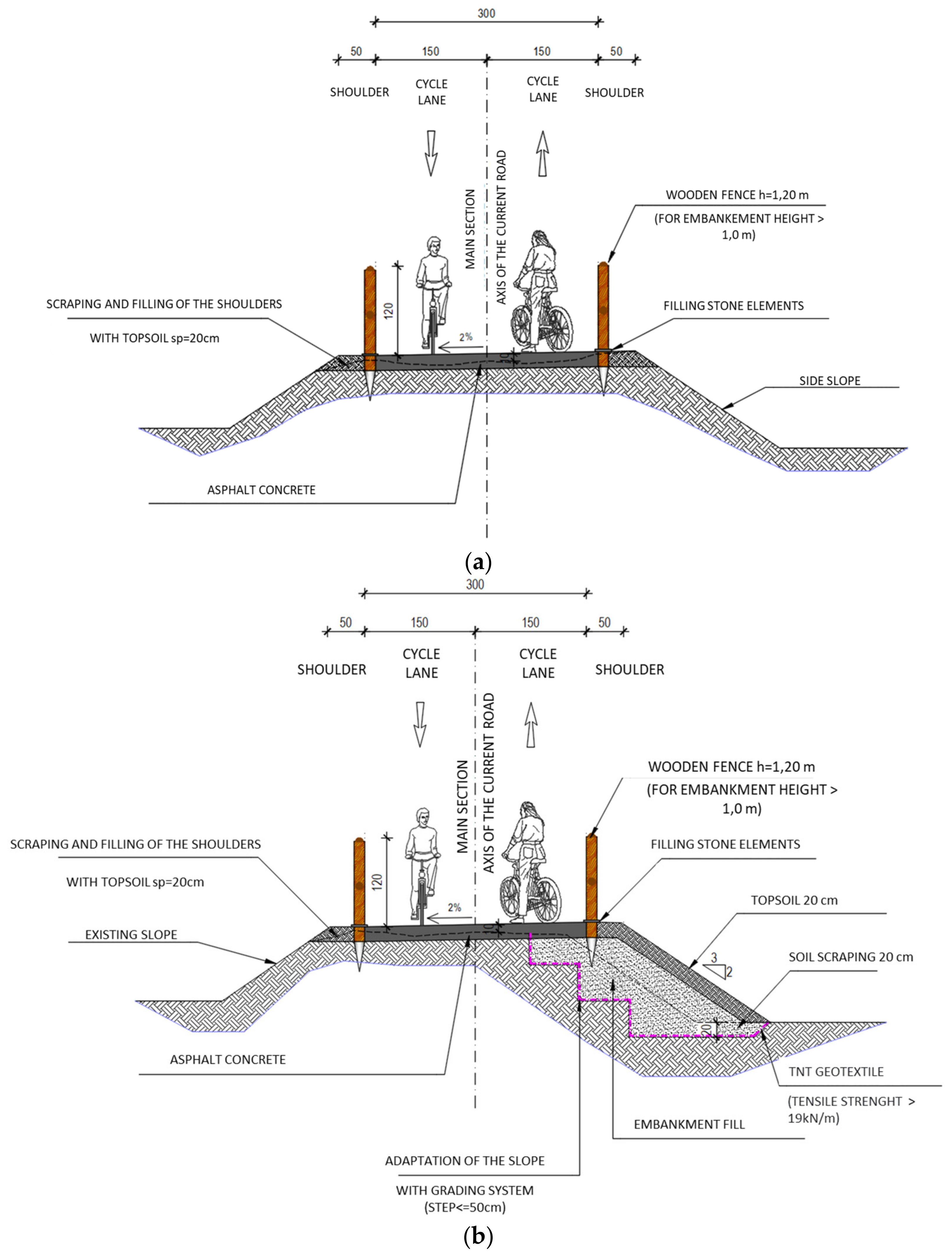
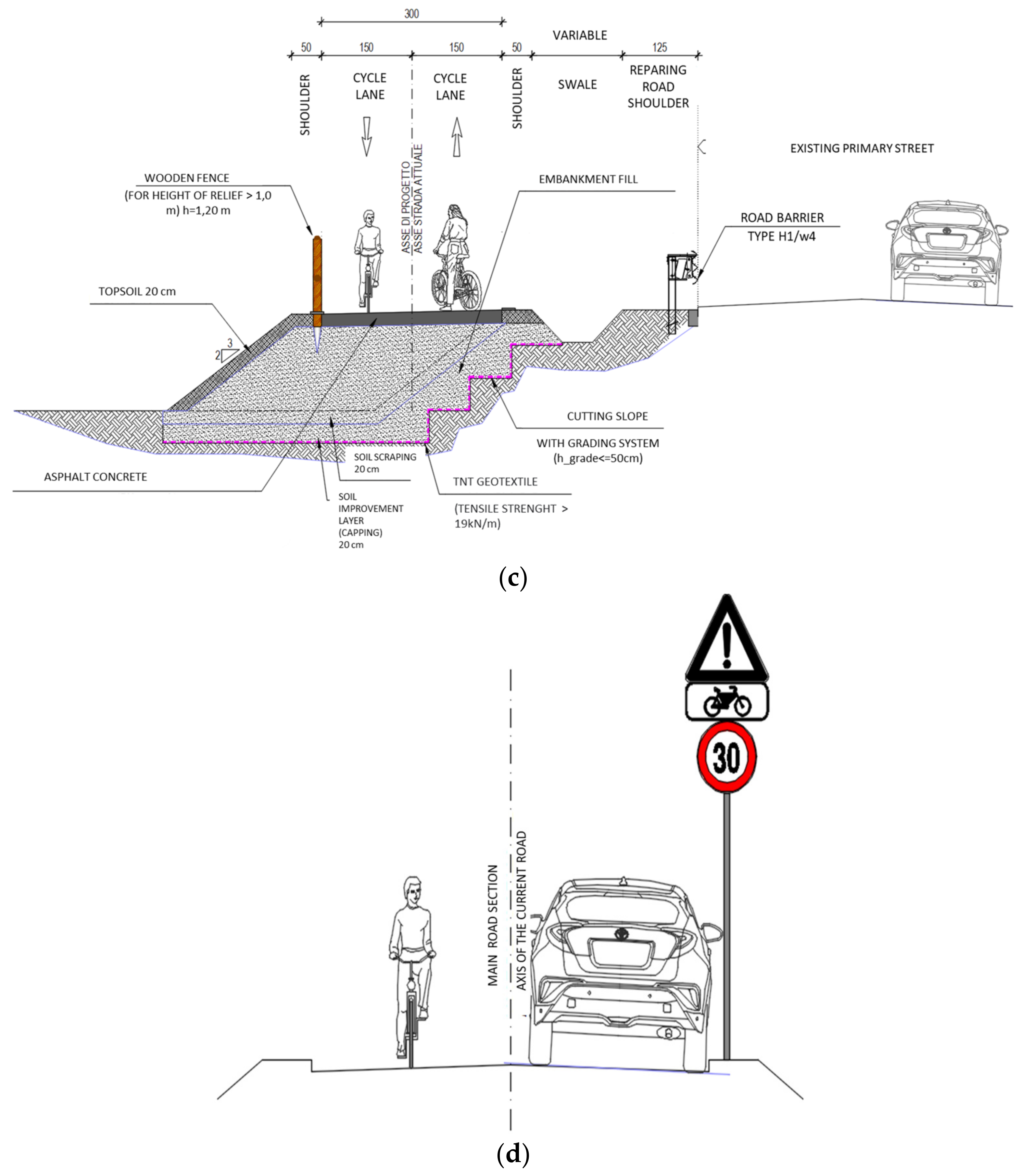
From an operational point of view, the design of a cycle path section involves the modelling of the infrastructure in all its aspects: a study of the route, analysis of interference, modelling of the infrastructure plan and of the longitudinal profile (altimetry), signage design, intersection study and relevant modelling. In line with the project guidelines, the project cycle path will primarily involve the Apulian aqueduct service track and, secondly, low-traffic roads, converted carriage roads and newly built sections. As already specified, the service track sections that are separated from the main road, where there is the transit of AQP service vehicles (or, for short sections, the transit of local residents who are otherwise unable to reach their properties) are to be considered as occasional. The cycle path will have a useful transit width of 3.00 m (1.50 m for each direction of travel) with exceptional and local reductions to 2.50 m at particular point interference, such as manholes or inspection wells or in urban areas where the standard width is not technically feasible or cost-effective. The surface of the track floor will be smooth and drained to ensure the safety of motion and braking. Consistent with the entire project, the floor will be made of a mixture of loose stabilized limestone adopting a molten grain size to ensure the closure of the mantle and its durability over time. In this way, the hygiene of drinking water transported in the Main Canal, on the service track, will be not compromised. For sections with a slope of more than 3%, mixed soil stabilized with cement will be used to ensure better resistance to surface erosion. In urban or mixed sections on roads with low traffic, the surface will be made of bituminous concrete. The transverse slope will be about 2% to ensure proper water drainage and an adequate coefficient of adhesion. Horizontal bending radii are generally designed with an internal radius of more than 5 m. visibility distance (regulated by the D.M. n. 2367 of 21 June 2004)is adequately sized to ensure safe stopping spaces. The longitudinal gradients are strongly influenced by the morphology of the land and by the need to maintain the path mainly on the AQP track. Normally, slopes are less than 5%; values of 10% are locally reached for short ramps. The route of a cycle path is mainly developed in three areas: on the AQP service track, on new paths and on existing low-traffic roads. For each of these situations, a typical section has been defined, and further detailed to consider the multiple situations at the boundary.
In detail, the type sections are as follows:
Typical section in embankment/trench/along the hillside on service path—routes with already adequate width (
Figure 1a);
Typical section in embankment/trench/along the hillside on service path—routes with insufficient width (
Figure 1b);
Typical section on newly implemented paths alongside existing roads (
Figure 1c);
Typical section for routes mixed with vehicular traffic (
Figure 1d).
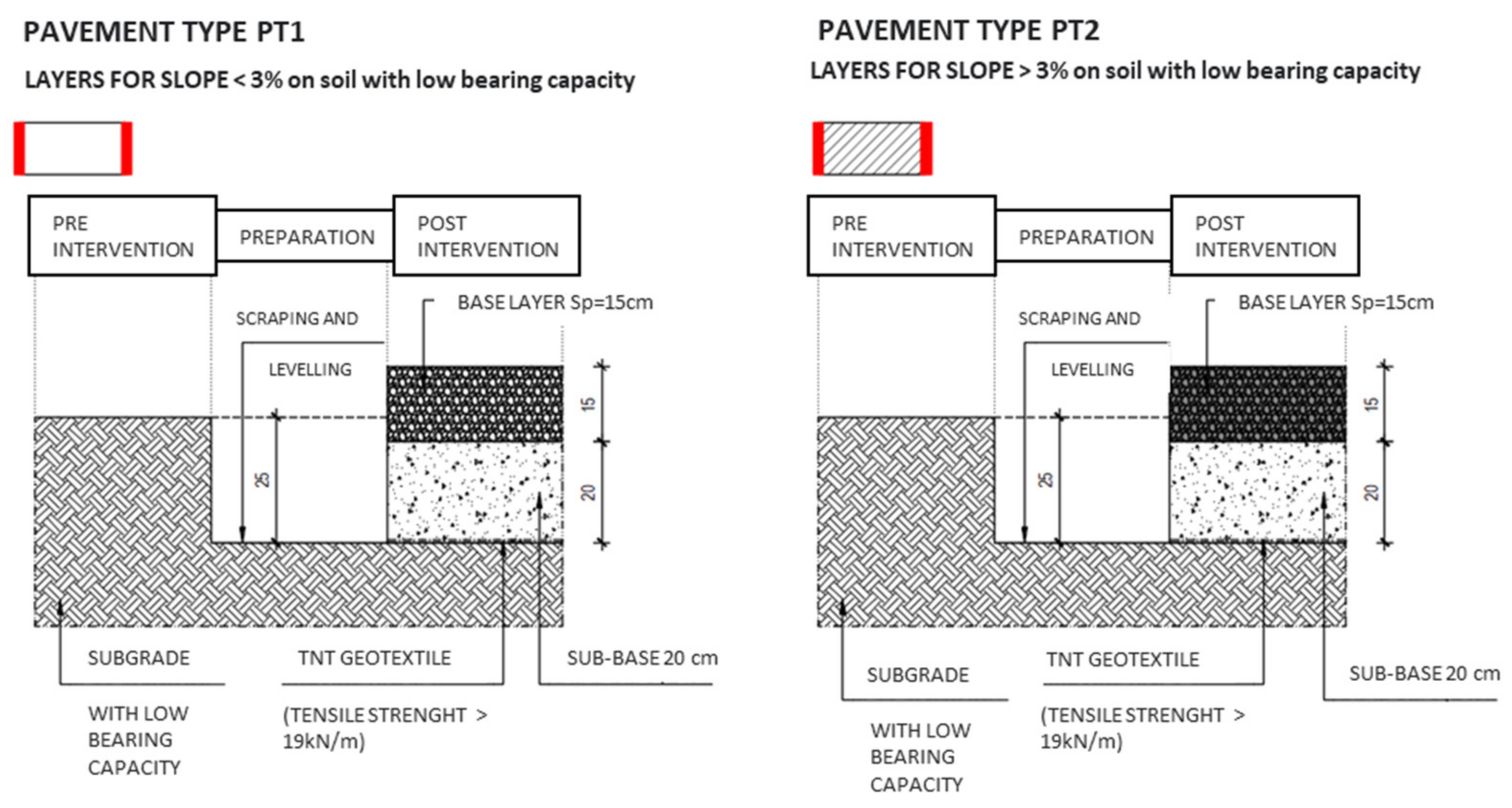
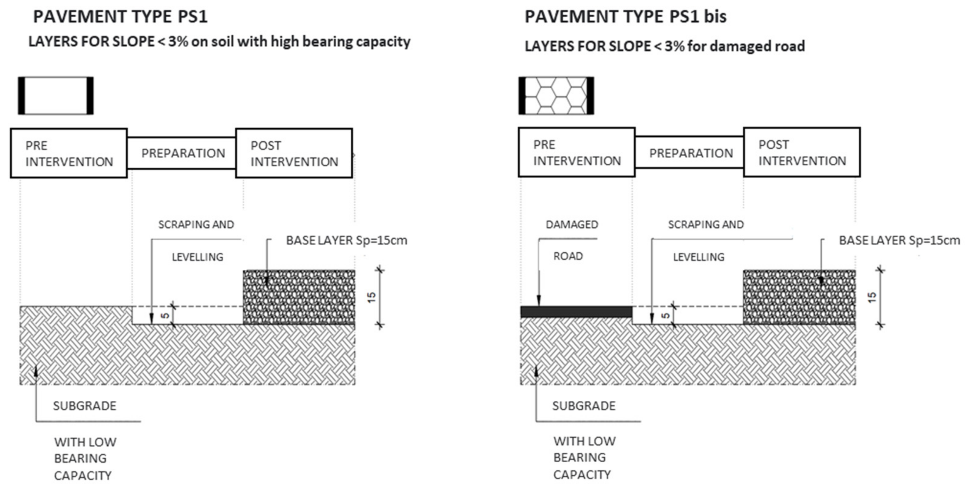
Most of the track is located on the current area of the AQP service track, whose sections have heterogeneous bearing capacities. For this reason, two main situations have been distinguished in the design phase:
Soil with low bearing capacity (PT layers type in
Figure 2);
Soil with good bearing capacity (PS layers type in
Figure 3).
The first case is typical of sections characterized by silty clay and organic soils, where the service track has the characteristics of a dirt track and turf often invades the track, recognizable by the groove of the wheels of vehicles. The original assorted gravel flooring has practically disappeared. In those sections where the longitudinal slope exceeds 3%, the surface layer is replaced by soil stabilized with cement. The second case is typical of the sections where the service track has kept the original assorted gravel path or is set on rocky (calcareous) soil.
AQP (intervention P1700) develops from the border with the Basilicata region (municipality of Spinazzola) for an extension of 34,925 km to Castel del Monte (municipality of Andria) entirely in the province of Barletta-Andria-Trani (BAT). The cycle path studied crosses three villages: Spinazzola for an extension of 17.20 km, Minervino delle Murge for an extension of 9.65 km and Andria for an extension of 8.08 km. The change in altitude of the section matches with the service road of the Main Canal and only locally overlaps the existing carriageways or reduced traffic roads. The average gradients of the sections are usually less than 5%; however, there are steeper ramps locally even more than 10%. To summarize:
Slopes with more than 5% inclination are extended for 3956 m equal to 11% of the total extension of the lot;
Slopes with more than 7% inclination are extended for 1419 m equal to 4% of the total extension of the lot;
Slopes with more than 10% inclination are extended for 176 m equal to 0.5% of the total extension of the lot; the most demanding ramp reaches a slope of 11% for a length of 60 m.
The steepest sections are located around the village of Spinazzola. The first kilometer of descent/ascent from Spinazzola towards the Murge and the last 700 m of descent/ascent towards the SP 222 are particularly challenging. In this sense, 7.5% of the planned route does not comply with the requirements of DM n 557/1999 and the Ministerial Directive Protocol 375 of 20 July 2017. However, since it is an adaptation of existing infrastructure and not new construction, it is considered appropriate to use the analogy with road designs that involve an adaptation of existing locations, whose legislation falls into D.M. n. 2367 of 21 June 2004. Therefore, the D.M. n.6792 of 5 November 2001 turns out to be an element to which to tend and not to have been complied with too fully. The present project has solved all the intersections of the cycle path with the territorial road network. The solutions were differentiated according to the administrative competence of the road, level of traffic, divided into low and medium/high (TGM over 500 vehicles/day), geometric characteristics (speed limit, width), and road surface of the interfering street. On the basis of these criteria, the following typological interventions have been identified and agreed upon with the operators of the interfering roads. Each of these interventions was developed for the specific situations identified in the project and listed below:
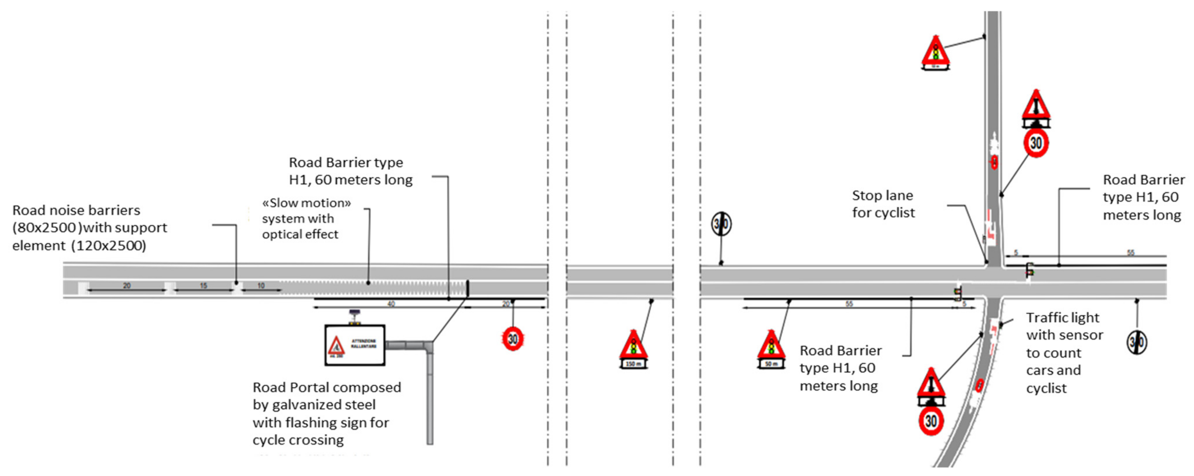
N01—traffic lights intersections for provincial roads of width greater than 6.5 m (
Figure 4);
N01bis—traffic lights intersections for provincial roads of width less than or equal to 6.5 m;
N01ter—traffic lights intersections for a cycle path on the road with the maximum degree of protection for the cyclist;
N02—intersections with enhanced signals
N03—municipal or local asphalted roads;
N03 bis—dirt local roads.
Analysing in detail the most innovative solutions to obtain the maximum protection in the traffic light intersections on the bike path is a sensor system. It can detect the presence of a bicycle or a car, stop traffic and allow access to the main road or its crossing in total safety. The cyclist’s priority is guaranteed by the insertion of a short, dedicated lane that allows the cyclist to stop in front of the cars and have a position ahead of the cars when the green is activated, keeping it throughout the crossing.
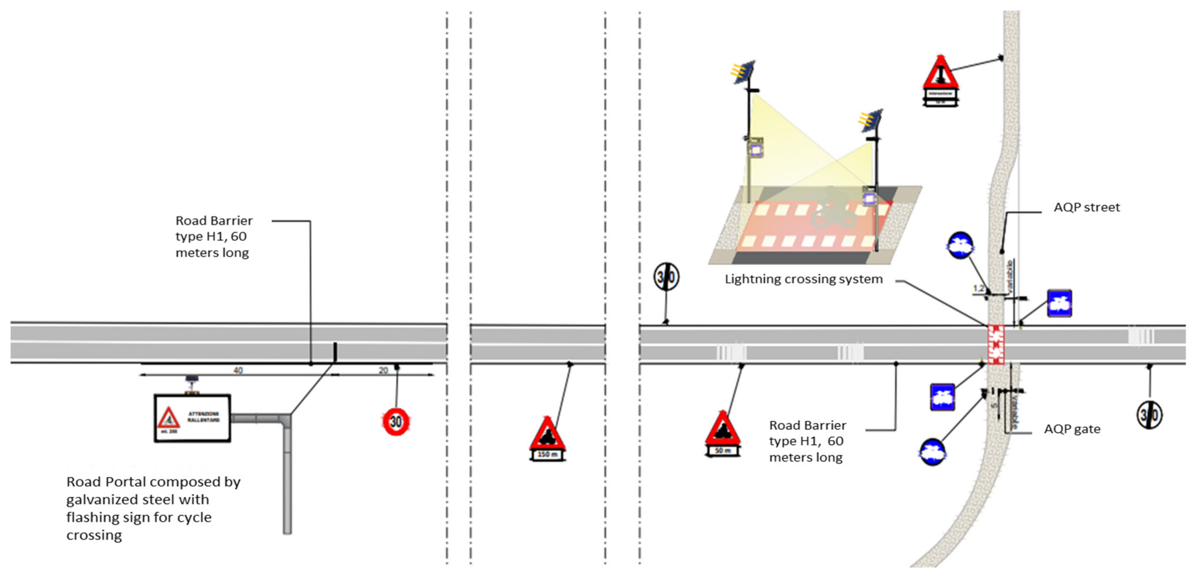
Another innovative design solution N02 (
Figure 5) has been used in the cases of crossing municipal roads, where bike crossing should be strongly signalled, but a traffic light is not necessary. This is because vehicle flows allow users to find the right time to easily cross the road.
Modelling of Section 3
Once the basic elements are found, the engineering design of the tourist cycle route can start. The design is carried out using the “Roads” software. First, the bicycle axis has been realized as a basic design element. Consisting of straight and curved lines, the axis has been obtained using a polyline, representing the route the cycle path will follow. The initial polyline design, equal to 35 km, has been broken into 7 sections to facilitate the modelling of the axis and to differentiate it later according to the specific characteristics of the territory in a certain stretch. This paper focuses on the modelling of the third section.
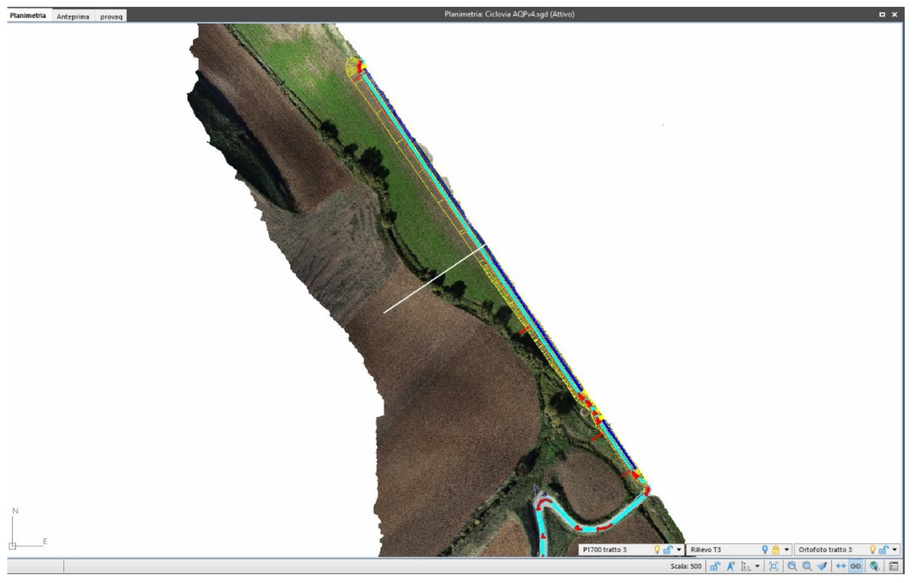
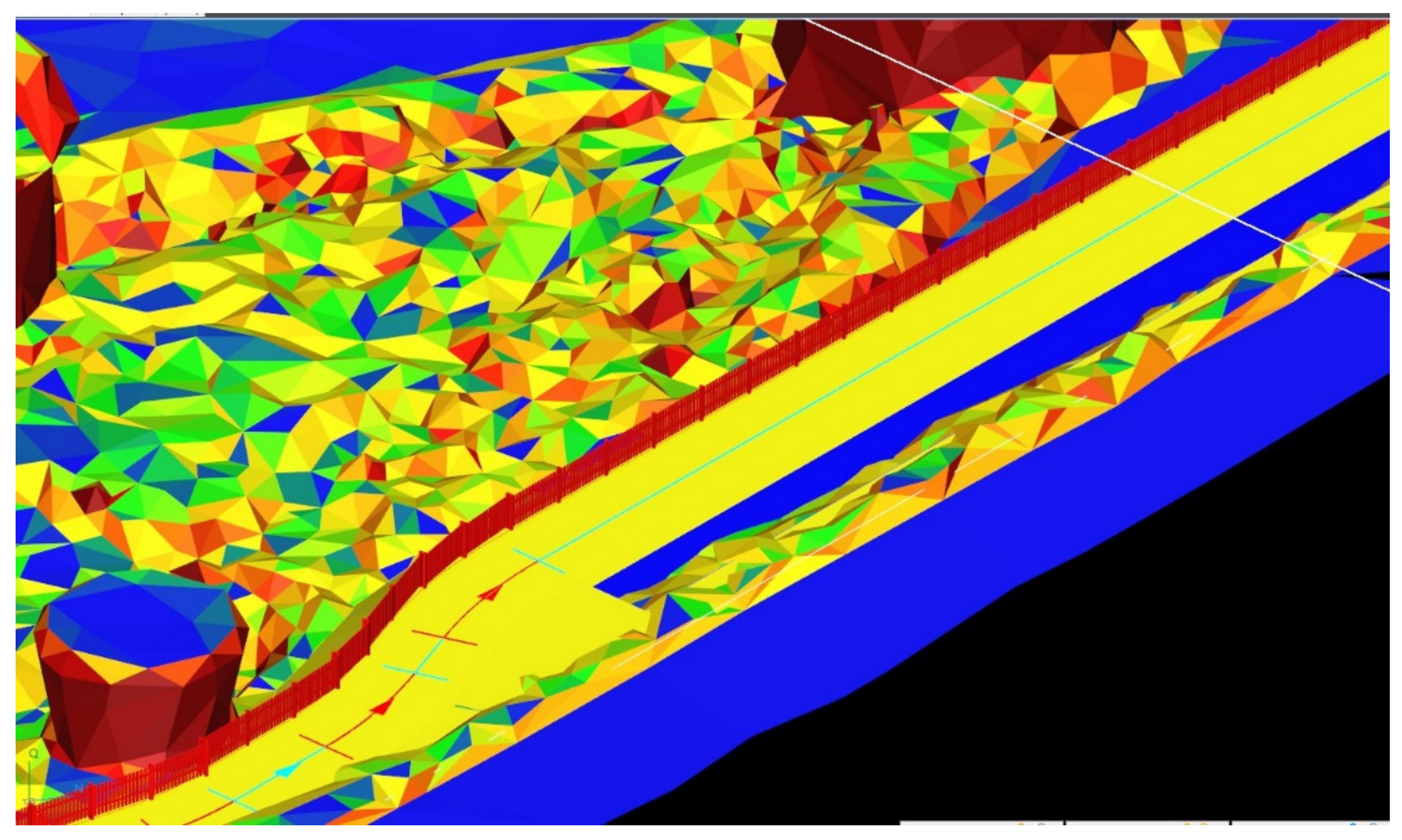
Reference elements such as orthophotos or drone surveys are used to obtain the cycling axis with the Roads software. Orthophotos represent a zenithal and georeferenced aerial photograph of a certain zone used for the aero photogrammetric (aerial) restitution of the topographic survey. Compared to traditional topographical surveys, drones allow a survey of a very large area in much less time than the more common procedure. In this case, drone detection is represented by a very large number of triangles, or DTM2 faces, which allow the analysis of the geographical context in which the axis must be modelled, exploiting the information in order to have a faithful 3D reproduction. The digital terrain model extrapolates the level curves, which are essential for calculating volumes. Having defined the axis of the cycle path from the planimetric point of view, it must also be managed from the elevation point of view. Defining the altimetry of an axis means assigning a reference quota to the graph at the lowest point of the profile and drawing some levels, such as straight segments of different slopes and lengths, reproducing the path of the ground as close as possible. Planimetry and altimetry of the axis are defined, and the generation process is performed. Next, the axis made at first is checked to really resemble the axis that will be modelled. Section by section it must be really in the centre line and not encounter any obstacles. The view of the section offers a precise picture of the geographical context, detecting possible earthworks, excavations or surveying, and so on. Once an axis consistent with all the data collected is established, platforms are defined based on the type sections within the specific modelling environment. Platforms faithfully reproduce the stratigraphy of the ground and represent the roadway, ditches, roadsides, slopes and all those elements necessary for the design. All these features can be parameterized and depend in turn on other elements that, in a sense, represent the geometric key data that, by varying, change all the others related to them.
In this project, platforms are multiple according to the division into sections operated at the beginning. Platforms can be differentiated immediately according to the slope of the levels. This difference basically consists of the creation of two types of carriageways:
The study of the project sections shows the differences between soil with low and high bearing capacity measured with a specific site test. When the platform is on the ground, in addition to the roadway, there is a sub-base 0.2 m thick.
As for the regulations, there is a big difference, both in theoretical and practical terms, in the construction of a bike path on its own headquarter to those made promiscuous. Separated cycle paths on their own headquarters run parallel to the carriages intended for vehicular traffic and are recognized thanks to physical separations such as curbs or pavements. Cycle paths with optical separation belong to this type: portions of the path indicated only by vertical and horizontal signs, without physical separations and reserved for the transit of bicycles. Cycle paths in promiscuous can be of different types:
Promiscuous urban cycle–pedestrian path: routes without physical barriers that separate the road intended for vehicular traffic from the cycle path;
Cycle paths adjacent to the pavement: a rather wide pavement allows two paths, the internal one for pedestrians and the external one for cyclists;
Cycle–pedestrian routes: usually found in green areas where access to motor vehicles is not allowed, or often also in cycle tourism itineraries.
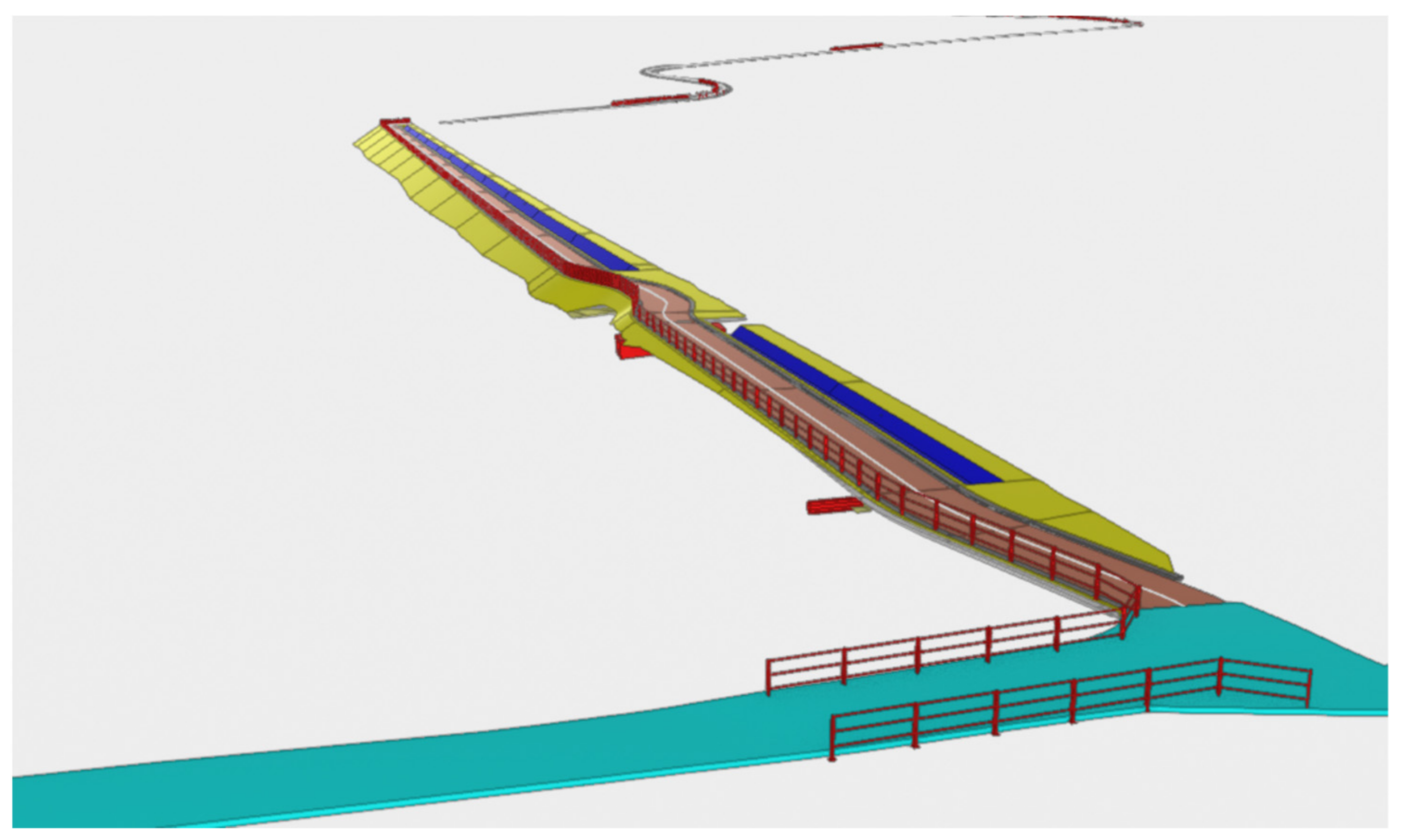
In the present case of the separate bike path, the analysis of the territory was fundamental to define the platform that more closely reproduced the best type section. In detail, the section will consist of a track width of 1.5 m, with a road pavement thickness of 0.1 m and a foundation thickness of 0.2 m. A realistic view (
Figure 6) and reliable axonometric (
Figure 7) of the design under consideration is allowed by the software.
Once the insertion of all standard platforms is finished, quantities are calculated for the definition of volumes and amounts of earthwork and ground survey. The calculation of quantities is made by cross-section polylines, each with its own code, and on the basis of the set calculation sequence. Calculating each partial area relative to a given layer, the final area of the layers is calculated as the sum of each single partial area. The line code (which defines the polyline of the reference section for the calculation of the partial area), the processing/characteristic (type of processing that will be performed from the set reference line, depending on whether it is earthwork or survey) the reference code (section code to be compared with the reference line set as “Polyline Code”) and the quantity code (reference code in a certain area calculated by the processing) are inserted within the calculation section. Before proceeding with the BIM of the final project, the last step is to model the signs, both horizontal and vertical, of the tourist cycle route. Operationally, vertical signage was designed from blocks related to the different signals of the Highway Code (previously created and inserted in the software library). For the horizontal signs, in addition to the insertion of blocks, the function “Smart Polyline” was used to realize, for example, the bicycle crossings.
Figure 8 shows the realization of the project for Section 3 of the tourist cycle route.
4. Discussion and Conclusions
Studying the literature on BIM, this tool has proved to be poorly applied to the transportation world but is mainly used in other different contexts. Several literature reviews have found that applications of visual programming tools have focused on architecture projects rather than infrastructure. However, the application of such tools in civil engineering projects is growing [
34] and, especially in the design of soft mobility infrastructures, BIM is useful to define the best project. The creation of a cycle path certainly represents an opportunity for environmental enhancement, a form of culturally evolved use of the territory and an opportunity to connect environmental and cultural emergencies with commercial activities and hospitality, thus contributing to the overall growth of the territory crossed.
All phases of design and BIM have been considered, leading to a model that will be realized during the project execution phase. The design of a cycle path is a complex operation containing aspects of the multidisciplinary character (engineering, spatial planning, economics, etc.) and is based on multiple needs: functional, structural and geotechnical, harmonious integration in the landscape, environmental, etc. The project pursues fundamental objectives such as integration of the infrastructure in the environment it crosses, convenience in order to develop an organic and safe cycling network, constructive choices aimed at maximum use and accessibility, sustainability in terms of durability and maintainability and life cycle of the works.
The objective of this study is to provide a complete analysis of the project for the realization of the tourist cycle path in Puglia. The design of the cycle path begins with the precise definition of the geometry of the territory with its altimetric profile. Then, sections and intersections are to be determined and, finally, the structural works to be encountered along the path (hydraulic works, architectural elements, lighting, signage, etc.). In the BIM phase, each object is defined by its properties: name, location, dimensions, materials and technical specifications. For the design and modelling of the track, “Roads”, an integrated software was used, available in the study of “Enser S.r.l.” and provided by Sierrasoft.
By producing realistic virtual simulations, I-BIM allows designers to compare different scenarios and select the best project in terms of feasibility, cost and environmental impact. Additionally, in the case study relating to the construction of a cycle path in the city of Catania, it is shown how the I-BIM approach is useful for the implementation of the choices promoted by the SUMP (Sustainable Urban Mobility Plan) [
35].
However, BIM also has some limitations. These are related to high implementation costs, the availability and quality of the information provided by the customer and suppliers of materials and equipment that must be carefully analysed and selected in order to use only those that are really necessary for design and construction. For these reasons, the design of this cycle infrastructure has shown little applicability and flexibility compared to BIM. However, given the regulations and the desire to move towards sustainable planning, increasingly focused on the construction of cycle paths, the necessity has risen to shape also the more marginal elements of the infrastructural planning with the new instrumentation to the disposition of the planners.
In the future, the use of the BIM methodology will lead to important developments in the infrastructure sector [
36]. Virtual reality will bring benefits to any type of construction site by simulating the construction process and identifying any problems before work begins. This will facilitate understanding of the projects, improve collaboration between the members of the different teams involved and increase security for all operators.


 ,
, 


