Article

Separate Track Impact Factor Application Depending on Track Types through Correlative Analysis with Track Support Stiffness

Department of Railway Construction, Graduate School of Railway, Seoul National University of Science & Technology, Gongneung-ro, Nowon-gu, Seoul 08826, Korea
*
Author to whom correspondence should be addressed.
Infrastructures 2020, 5(2), 17; https://doi.org/10.3390/infrastructures5020017
Submission received: 23 December 2019 / Revised: 30 January 2020 / Accepted: 4 February 2020 / Published: 6 February 2020

Abstract

:
Track impact factor (TIF) is a coefficient for estimating the increase of train dynamic load and is a major factor for the evaluation of dynamic stability of railway tracks. Many kinds of TIF in ballasted and ballast-less slab tracks consider only speed as a variable in different regions of the world. Because of this lack of clarification, nations such as Korea and those in the Middle East, and South East Asia are implementing overly simplified calculation methods for TIF, resulting in inconsistent maintenance of different railway track types. A comparative analysis of theoretically track support stiffness (TSS) and trackside measurement calculated TSS at wheel-rail contact point shows different values (depending on speed) between ballasted and ballast-less slab tracks. Based on this finding, this paper investigates a TIF formulation method that considers both dynamic wheel load and speed as variables, and a separate application of TIF formulation depending on track types is proposed. A clarified distinction of how these parameters (TSS and TIF) interact differently between ballasted and ballast-less slab track structures can be an important factor in case of track designing and maintenance aspects.

Graphical Abstract

1. Introduction

Many design guidelines for track structures and components evaluate the structural stability through theoretical and real-time evaluation of the components found in the superstructure, and the nature of these loads and design parameters and how the design process reflects them must be understood [1]. Within the evaluation regime of track structures, track impact factor (TIF) is used as a key variable for load estimation on the track structure. Priest, J.A. indicates that adequate track support is crucial to understand the ride quality and reducing track and vehicle maintenance costs. Otherwise, it can result in the development of adverse track geometry and increased vehicle loading and track damage [2].
There are several track impact factor calculation methods, and the respective methods are perceived differently in the field of railway construction. Konstantinos Giannakos quotes two main methods of TIF formulation methods, one by Eisenmann and another by Prud’homme and provides a parametric investigation on the applicability of the respective design methods based on crack formation of different track sites [3]. Balmaseda Lucia compares Eisenmann’s and Prud’homme’s dynamic amplification coefficient (DAF) calculation and outlines the limitations of the former in the lack of consideration for the stiffness of the track structure [4]. Brandon J. Van Dyk et al. identifies the existing calculation methods for TIF (design factors) and evaluates their effectiveness based on wheel loads using old and new evaluation regimes [5].
Because of the complexity of a railway track system, it is difficult to claim that one TIF calculation method is objectively superior or more accurate than other, and environmental and design parameters must be fully taken into consideration by experienced infrastructure owners for the selection of the appropriate design method [6,7]. To supplement on this point, there has not yet been a clear research on the risks of improper design method, and this pertains to the dynamic stability evaluation methods for ballast-less slab and ballasted track structures. It is commonplace knowledge that ballast-less slab track construction costs far outweigh that of the ballasted tracks as a concession for lower life-cycle cost and longer service life. Köllő et al. provides a detailed explanation on the difference in the two types of railway tracks, in terms of property differences of materials used (aggregates of ballasted tracks, and the elastomeric fasteners and paddings in ballast-less slab tracks), construction and maintenance costs, and deterioration rate [8]. Generally, it is known that in ballast-less slab tracks that concrete material is weak to vibration because of their low energy dissipation capacity, hence resulting in the commonly known noise radiation problem [9]. In contrast, ballast tracks are not vulnerable to noise problems, but have a problem with frequent track deformation related irregularities [10].
Despite these diverse differences between track types, in regions such as Korea, the criteria and evaluation methods of both types of tracks is conducted using the same theoretical model relative to the track conditions (φ) and geometry, and load conditions [10]. In most cases, the different track types are rarely required to be compared between one another, and even in such rare cases the total spring stiffness of the respective track types is enough to account for the difference. With regards to the dynamic loading factors however, shared dynamic stability performance evaluation can produce improper assessment of the track structure which could bring about inaccurate maintenance regulation procedures. To illustrate, based on an existing study that compares the track support stiffness (TSS) of various railway track sites, the TSS of ballast-less slab tracks ranged on an average of approximately 60 to 70 kN/mm, and 100 to 130 kN/mm for ballasted tracks [10].
Lee’s study continues to explain that while TSS derived theoretically and TSS derived from trackside measurement have a distinct difference between ballasted and ballast-less slab track structures, the theoretical calculation of the TIF is the same for both, as the only variable used is the speed of the train [11]. The basic foundation of TIF is that this factor is the ratio of the dynamic response to the static wheel load, where dynamic wheel load is larger than static wheel load because of the various factors such as rail surface roughness, track irregularity, and track support stiffness. To illustrate the significance of this, Nimbalkar et al. provides a detailed study on the dynamic track modulus evaluation of modified beam on an elastic foundation is found to be influenced by train speed, placement and synthetic inclusions, type of subgrade, and axle load [12].
However, despite the significance of this property, only the British Railways employs track stiffness at rail joint as a factor for calculating the dynamic factor, and other existing standards do not use this factor. While impact factor depending on the dynamic effect of wheel and rail irregularities, and the dynamic effect of wheel depending on track stiffness should be a common knowledge in the field of modern railway engineering, the practice of calculating dynamic factor using TSS is not common, especially in regions such as Korea, China, Middle East, and South East Asia. Brandon J. Van Dyk et al. offers a comparison of existing different types of impact factor calculation and the parameters considered to illustrate this point [5]. Refer to Table 1 below for details.
Particularly in rail track transition zones, a precise understanding and assessment of track conditions is crucial for track maintenance. Roberto Sanudo et al. discusses this point in detail, where by using finite element software, making small changes in the track structural elements can improve drastically reduce the stress in the transition zones [14]. Along with modifications to the structural elements, it is important to precisely understand and accurately detail the continuous interaction between the track and the moving vehicles at the wheel-rail contact by providing the track impact factor values of ballasted and ballast-less tracks that considers the most crucial factors such as TSS. Based on this background, it is proposed that (1) TIF calculation should take into consideration the TSS derived from the dynamic wheel load and the displacement of the rail, whereby a TIF that considers the important factors for rail deterioration is taken into account for track maintenance and quality assessment, and (2) in doing so, a separate application of TIF calculation method using dynamic wheel load derived from trackside measurement should be proposed for ballast and ballast-less tracks respectively.

2. Theoretical Discussion and Review

The following sections provide a review of the general principles of TSS (existing calculation methods and variables), dynamic wheel load and TIF to establish correlative connection between the different parameters. An explanation on the general concept of spring stiffness, followed by a TSS calculation method and the association of dynamic wheel load to the principles of TIF calculation is provided. Note that the comparative logistics between TSS and TIF calculation methods dealt with in this paper are compliant to Korea Railroad Authority’s Track Design Standard (KR-C 14030) (derived from the AREMA standard) [15]. As such, requirement for this comparison may vary in accordance to different situations and national standards/specifications.

2.1. Spring Coefficient and TSS Calculation Methods

Track support stiffness point is an indicator of vertical stiffness at the wheel-rail contact point (bearing capacity against operating train wheel loads) of a track [16]. However, there is no complete consensus on the precise definition of track stiffness, but Konstantinos attempts an explanation of the concept by outlining the difference between track stiffness which is defined by the elastic rail deflection that takes place under a wheel loading, and track modulus which is the measure of the vertical stiffness of the track foundation [16]. In this paper, the track support stiffness (TSS) refers to the track stiffness at wheel rail contact point in accordance to Konstantino’s definition.
In many national standards, TSS measurement leads to an understanding of the rate of track geometry deterioration or deformation because of the dynamic load [17], but most important is a factor for understanding vehicle operation stability in transition zones. As such, it is important to maintain the optimum value of a track’s total stiffness (TSS) particular to the specific track characteristics and environment to minimize the maintenance effort.
In finite element method, track modulus (the vertical stiffness of the entire track structure including superstructure and substructure) is derived by the comprehensive spring coefficient from the individual components that comprise the entire track structure. Among the currently existing methods, AREMA implements the following equations below where (Equation (1a)) the spring coefficient k s   is derived by calculating the spring coefficient of the individual components/layers of the ballasted track structure (Equation (1b) for ballast-less slab track structure) and (Equation (2)) the spring coefficient k s is used to calculate the track modulus of the structure [18];
k b s = 1 1 k p + 1 k s l + 1 k b + 1 k s g
where,
  • k p : the stiffness of the rail pad (kN/mm),
  • k s l : the stiffness of the sleeper (because of the compressibility of wood in the rail-seat region and sleeper bending) (kN/mm),
  • k b : the stiffness of the ballast layer (kN/mm),
  • k s g : the stiffness of the subgrade (kN/mm), and
  • k b s : the stiffness of the ballasted track structure (kN/mm).
k b s s = 1 1 k p + 1 k r + 1 k s l + 1 k s l a b + 1 k s g
where,
  • k p : the stiffness of the pad (kN/mm),
  • k r : the stiffness of the resilience (if applicable) (kN/mm),
  • k s l : the stiffness of the sleeper (if applicable) (kN/mm),
  • k s l a b : the stiffness of the ballast-less slab (kN/mm),
  • k s g : the stiffness of the subgrade (kN/mm),
  • k b s s : the stiffness of the ballast-less slab track structure (kN/mm).
K t = 64 E I d 3 4 K s 3
  • E: modulus of elasticity (GPa),
  • I: moment of inertia (mm4),
  • d: distance of the sleepers (mm),
  • k s : stiffness of the track structure (kN/mm),
  • k t : track support stiffness (kN/mm).
Changes in vertical track stiffness can cause numerous problems to smooth train operation in tracks. According to Henrik Lund’s research, the response from vertical track stiffness changes causes dynamic forces that can cause track degradation, ride discomfort, and increased vibrations [19]. The modulus of subgrade reaction is a measure of the subgrade stiffness at the lower edge of the sleeper, specified as the ratio between the contact pressure against the substructure. The stiffness below the sleeper can vary in the order of a factor of up to ten [19]. The variations in stiffness are equalized by the load distribution of the track through the flexural stiffness in the rails [19]. In this regard, Lund indicates the flexural stiffness of the superstructure crucial in understanding the track stiffness [18].
In light of this finding, the stiffness factor of the track component of the rail which is at the wheel-rail contact point, is crucial to understand the relationship between the track and the moving vehicle. When the overall modulus of elasticity of the track is low as is the case with ballastless tracks (which indicates low differential settlement rate of track structure), the load at the wheel-rail contact point causes displacement at the sleeper and the ballast [20]. In the case of ballasted track, the settlement throughout the track structure is high because of the high modulus of elasticity and rail displacement because the wheel load is relatively small while the wheel load generated on the overall track structure (high differential settlement rate of the overall ballasted track structure) in consideration of the different layers becomes large.
For theoretical calculations of track support stiffness at wheel-rail contact point, there are number of standardized methods, among which select methods (such as Kerr’s method that was cross examined with the existing traditional method TSS calculation methods) have shown to be more accurate through consideration of more realistic track structure conditions [21,22]. To emphasize the importance of consistent measurement of the effect of wheel load on the rail, dynamic load is an essential criterion for determining the dynamic stability performance of the track structure. Dynamic load is calculated by the principle of deriving the effective load (Qeff) factored by cant deficiency [23];
Q e f f = Q × 1.2
Subsequently, the following formula is used for the dynamic load because of the exceptional impact caused by the vertical vibration of the vehicle’s elastic part caused by irregularity at the wheel/rail contact point [10];
Q d y n = Q e f f × DAF
where,
  • when V ≤ 60 km/h, DAF = 1+ t ϕ
  • when passenger train speed is 60 < V < 300 km/h, D A F =   1 + t ϕ ( 1.0 + 0.5   V 60 190 )
  • when freight train speed is 60 < V < 160 km/h, D A F =   1 + t ϕ ( 1.0 + 0.5   V 60 80 )
  • Q: Static wheel load (kN),
  • Q e f f : Effective wheel load (kN),
  • Q d y n : Dynamic wheel load (kN).

2.2. Performance Criteria for Track Dynamic Stability

TIF is the ratio of the dynamic wheel load to the static wheel load and dynamic wheel load larger than static wheel load because of the various factors such as rail surface roughness, track irregularity and track support stiffness, and is a key factor for a dynamic stability performance evaluation in railway track structures [23]. The common definition of track impact factor I can be outlined with the equation below;
I = m a x   d y n a m i c   r e s p o n s e m a x   s t a t i c   r e s p o n s e

2.2.1. TIF Calculation Specifications

As is described in the above, different national specifications for track design employ different variables for TIF calculation, and as each method respectively considers different aspects of the track environment and structural conditions, the theoretical application of the selected TIF calculation method must be taken into consideration [24]. Cases of dynamic performance evaluation in Korea exemplifies the risks of improper dynamic stability evaluation of ballast-less slab track structures because of different TIF calculation results. As Balmaseda explains in his paper, the formula proposed by Eisenmann’s TIF calculation method considers the quality of the rail track and maximum speed of train, but this method was revised such that Eisenmann’s new formula now adapts the cases of high-speed track structures [4]. Retrospectively, Prud’Homme’s formula introduces a new criteria and reveals how the vertical rail track stiffness, weight of the vehicle, rail track quality, and vehicle speed affect the dynamic loading on the rail [4]. When the numerical model results derived from the respective two formulae are compared, the difference between the coefficient derivation can be observed. Refer to Figure 1 below for details.
When comparing the results of Prud’Homme and Eisenmann, Prud’Homme’s track impact factor coefficient increases relative to the stiffness value of the track, as it should be owing to wheel load increasing relative to the speed of the train. In this regard, the increasing track stiffness indicates increasing speed. Because of the difference in the variables used in the application of the respective theoretical models, it shows that Eisenmann’s method is derived such that the TIF is higher for the track structure in the sections with low TSS, but in the sections with higher TSS (past approximately 120 kN/mm), Prud’Homme’s method-derived TIF surpasses that of Eisenmann’s TIF [4]. Balmesada’s investigation pertains mainly to the different TIF calculation of the same types of the track structures with the same quality (track condition = 0.2 (good)). This study aims to investigate outcome of using the same TIF calculation for different track types (ballasted and ballast-less slab track structures). In the following section, track dynamic stability evaluation conducted for ballasted and ballast-less slab track structures respectively in Korea is investigated for this investigation.

2.2.2. Theoretical Derivation Method and Trackside Measurement Method Comparison for TSS

Korea employs the KR-C 14030 standard for the dynamic stability performance of track structures which was adopted from the AREMA specification. For the trackside measurement of TSS, Hooke’s law is implemented to calculate the track support stiffness to derive the immediate TSS value/condition of the track structure. As in accordance to Hooke’s formula, the track support stiffness is derived using the variables of maximum dynamic wheel load during trackside measurement, and the maximum rail displacement (deflection);
K t = Q d y n δ m a x
where;
  • K t : is the trackside measurement based track support stiffness (kN/mm);
  • P m a x : is dynamic wheel load (maximum value derived from trackside measurement) (kN);
  • δ m a x : is rail vertical displacement (maximum value derived from trackside measurement (mm).
Lee conducted an investigation on the comparison of TSS properties in accordance to the above calculation method between ballasted and ballast-less slab tracks in a previous study. He investigated the maximum dynamic wheel load values and rail vertical displacements of ballasted and ballast-less slab tracks and derived the averaged TSS values of based on to provide a comparison between the two track structure types. Refer to the below Figure 2 for details.
Numerous similar studies in Korea indicate that the average TSS values of ballasted track structures is around 130~160 kN/mm, while ballast-less slab track TSS values range at a wider range between 60~120 kN/mm [10]. These investigation results are in accordance with the findings of numerous other scholars such as Giannakos, who indicate that track support stiffness varies in accordance to the rail conditions (surface irregularities, geometrical deformation tendencies of the track structures, and track conditions, etc.) [22]. In light of this findings, Lee continues his investigation in another study, where a correlative analysis of TIF and TSS was conducted between subway ballasted and ballast-less slab railway tracks and high speed railway tracks [10]. Refer to Figure 3 below for the conclusive graph on the correlative analysis of TIF and TSS in Lee’s paper.
In his investigation, the respective difference of TSS of ballasted and ballasted tracks (approximately 125~210 kN/mm for ballasted tracks and 27 to 64 kN/mm for ballast-less slab tracks) is evident. However, as the specification on the TIF calculation in the KR-C 14030 accords with the Eisenmann method, the TIF range for both ballasted and ballast-less slab track structures resulted in deriving the same range of coefficients [14]. It is predicted that this is a result of the TIF calculation that considers only the maximum speed. This situation demands a sequential investigation to verify whether a separate application of TIF is necessary or not through a comparative analysis of TIF calculation methods using TSS (derived from maximum dynamic wheel load measurement).

3. Trackside Measurement Method (Materials and Specification)

For this investigation, speed parameters from 80 to 210 km/h for ballasted tracks, and 120 to 230 km/h for ballast-less slab tracks was selected, with plans to measure in the averaged intervals of 10 km/h (certain intervals were impossible to measure as the high-speed track operation conditions did not allow certain speed intervals). Five ballasted track sites and five ballast-less slab tracks were selected on high-speed line in Korea to conduct the trackside measurement for the TSS and TIF comparative analysis. Track facilities were capable of operating at maximum speed of 200~250 km/h in high-speed line sections, and the track construction design complied to railway track structure performance test standards (KR-C 14030). Only the tracks with similar geometric conditions, previous track performance evaluation records, and track condition factors (used for calculating the TIF via Eisenmann’s method, Φ) of 0.2 were selected for this study to provide as consistent as possible results for this investigation. In case of value t, t = 3 was applied because of the fastener excess probability based on Eisenmann’s equation.
In each track type, the site measurement was conducted between 10 to 15 times (different for each track facility because of the operation scheduling requirement). Trackside measurement was conducted for only one specific vehicle type throughout the entire investigation (KTX-Sancheon). Once trackside measurement was completed at each track facility, measurements were categorized in accordance to the speed, and the measurement results were averaged between the speed categories (for example, measurements with cases of train speed from 80~90 km/h were averaged). Refer to Figure 4 below for an illustration of the example railway track sites selected; Table 2 for the specifications of the track structure and conditions; and Table 3 for the vehicle specifications.

3.1. Trackside Measurement Method

Trackside measurement consisted of five criteria for determining the dynamic response properties of the ballasted and ballast-less slab tracks. The criteria consist of vertical wheel load, lateral wheel load, rail stress, vertical rail displacement, and lateral rail displacement. The following sections provide an explanation on the required trackside measurement equipment specifications and procedure.

3.2. Trackside Measurement Equipment

Dynamic wheel-rail forces (wheel load) were measured using shear strain gauges coupled to a full whetstone bridge circuit. Rail deflection (displacement) was measured using linear variable differential transformers (LVDT). Data collection was conducted using a data acquisition device (MGC Plus SDA-8 channel). Required equipment for the trackside measurement are shown in Table 4 below.

3.2.1. Equipment Installation and Trackside Measurement Conditions

Dynamic wheel load (vertical wheel load) was calculated by measuring the shear strain and at a distance of 100 mm from the center point between sleepers. Biaxial strain gauges were installed on the rail surface in eight directions with an angle of 45 degrees along the neutral axis of the rail web at a distance of 100 mm from the center of the sleeper. In the case of lateral wheel load, the bi-axial gauge is attached at a position of 46 mm inward from the rail bottom surface.
For displacement measurement, anchors are installed at the rail side and linear variable differential transducers (LVDT) are installed onto the fixed anchors. The LVDT heads are installed on the upper surface of the rail bottom (vertical rail displacement measurement) and facing toward the rail web from the side of the rail (lateral rail displacement measurement). The bending stress of the rail was measured by longitudinally attaching a one-axis strain gauge to the bottom flange of the rail at the center of two consecutive sleepers. To eliminate the interference from other passing trains, and to obtain a reliable measure of the wheel load of the current passing train, to prevent data distortion and loss, the sampling rate was set to >1 kHz. Refer to the Figure 5 below for details on the installed trackside measurement equipment sites.

3.2.2. Dynamic Wheel Load Calculation Using Shear Strain Data

The measured strain value during trackside measurement is converted into rail stress by multiplying the modulus of elasticity of steel (approximately 205 GPa). Wheel load, lateral wheel load values were calculated by multiplying the strain value and coefficient which was obtained through calibration process with an accuracy of 2%. This coefficient was calculated using a hydraulic ram, and a load cell which can get the kN value using strain value. Refer to Figure 6a,b below for the illustration of strain gauge calibration, and Figure 6c,d below for a sample calculation for coefficient to get the load value.

4. Trackside Measurement Results and Analysis

In the five different track sites for ballasted and ballast-less slab tracks, the measurement results of the track performance variables are outlined in Table 5 and Table 6 below respectively. Results are presented relative to the speed parameters measured from site, and the maximum values from each track performance variable measurement results were averaged. The data for the respective parameters was then used to derive a relation graph and the details of these graphs are provided in Figure 7 below.
Among the track performance variables, wheel load and vertical rail displacement were used to calculate the TSS and TIF of track. In case of wheel load, the value was measured to be higher in ballasted track than ballast-less slab track at a minimum of 0.03% and maximum of 8%. For vertical rail displacement, the value in ballast-less slab track shows higher values by minimum of 18% and maximum of 95%. Based on the measurement data, TSS is calculated and compared with theoretical TSS, and TIF is also derived and compared with theoretical TIF (depending on track type). Results of track dynamic response measurement of ballasted track and ballast-less slab track is shown in Table 7 and Table 8 and Figure 8.

4.1. Result of TSS

Distance between the sleepers, rail section properties, and the rail supporting point spring stiffness derived from the rail pads and the anti-vibration pads with reference to the track structure design were used to calculate the theoretical TSS. In case of field measurement TSS, it was calculated as the ratio of the maximum rail vertical displacement and maximum wheel load according to the train operation. Calculated theoretical TSS and field measurement TSS results are as follows.
Comparison and analysis of theoretical TSS and TSS obtained from trackside measurement depending on the track type were performed. In ballasted track, the TSS calculated by trackside measurement is about 37~98% larger than the theoretical TSS and 7~23% larger in ballast-less slab track. In case of comparison depending on track type, TSS in ballasted track shows higher value than ballast-less slab track from minimum 1.18 times and maximum 1.96 times. From the above results, TSS values shows big difference according to the track type, and it is necessary to apply the separation depending on the track type.

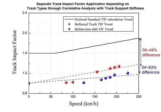
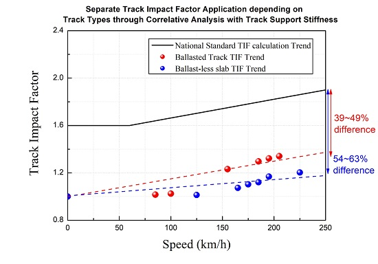
4.2. TiF Comparison between Track Types

Using the acquainted data (especially wheel load) from field measurement, calculation was performed inversely and comparison with theoretical TIF was performed. In case of wheel load, the largest values among the results measured for each wheel were used to calculate TIF.
In case of measured maximum wheel load, the value increased linearly as the speed increased. Depending on the track type, the value at ballasted track was larger than that of ballast-less slab track and both value were higher than 85 kN (static wheel load). For the value of TIF, measurement TIF was 59.84~66.19% smaller than the theoretical TIF in ballasted track and 54.78~68.21% in ballast-less slab track. When comparing the TIF between calculated from the measured results and with the theoretical TIF currently used in track design in South Korea, it was observed that the theoretical TIF was larger than the TIF calculated from the trackside measurement, and TIF value of the ballast and ballast-less slab displayed a difference in slope in the linear regression calculation as is shown in Figure 9 below.
Using the data above, a graph to represent the respective trend for the changing TIF of ballasted and ballast-less track was derived with the three TIF calculation methods. As use of linear regression does not often correctly describe the TIF changing trend because of significant over prediction of track impact factor at high train speeds. However, for reference purpose, a dotted trend line was provided over the data, and the results below only serve as a demonstration of the estimated comparison method of the respective track types’ TIF, outlined as the following;
  • Korea Railroad Authority’s Track Design Standard (KR-C 14030);
  • TIF(DAF) using the trackside measured data in Ballasted track;
  • TIF(DAF) using the trackside measured data in Ballast-less slab track.
Above results show that TIF of KR C-14030 shows the highest value, followed by TIF of ballasted track and TIF of ballast-less slab track. TIF of the KR C-14030 differs from the TIF of the ballasted track 39~49% and 54~63% in ballast-less slab track at the train speed of 0~300km/h.
Comprehensive results showed the TIF calculated from the trackside measurement is different from the theoretical TIF, and separate application of TIF with considering the track type is inevitable.

5. Conclusions

The comparative analysis of TSS and TIF between ballasted and ballast-less tracks and the comparison of TIF calculation considering the respective dynamic wheel load of ballasted and ballast-less slab tracks are as follows:
1. TSS of ballasted and ballast-less slab tracks derived from between trackside measurement was compared as a ratio to the theoretically derived TSS (using the spring coefficient of the track structure). Theoretically calculated TSS for ballasted track (with respect to the track structure specifications) was 137.14 kN/mm, and the TSS was 62.62 kN/mm for ballast-less slab track. It was shown that in the case of ballasted tracks, the ratio (%) in the TSS ranged from approximately 37~98%, and for ballast-less slab tracks, the difference in the TSS ranged from approximately 7~23%.
2. As a correlative relation between TSS and wheel load, and in sequence, a requirement for considering wheel load in TIF calculation is established, a TIF calculation based on KR-C 14030 (Eisenmann’s method) was derived for each speed parameter selected for the trackside testing. Based on this calculation results, the TIF of ballasted and ballast-less slab track was respectively derived using the dynamic wheel load data obtained from the trackside testing. The TIF results were then correlatively compared to the theoretically derived TIF. In the case of ballasted tracks, the TIF derived from trackside measurement had a decrease as a ratio from the theoretically derived TIF by approximately 60~66%, and for ballast-less slab tracks, decrease of approximately 55~68%.
3. According to the conclusion 1 and 2; the applicability of the current method of TIF calculation without consideration of TSS values was investigated, and this paper demonstrates that a different TIF calculation can be derived depending on the track structure. Correlative analysis results of TIF for ballasted and ballast-less slab track structures based on KR C-14030 and TIF (theoretical TIF), and field measurement TIF shows that KR C-14030 TIF value is very different from that of the TIF.
Based on the countries using various national railway track design and maintenance specifications, issues concerning the improper dynamic stability evaluation of track structures still exist. In case of Korea, TIF calculation traditionally is conducted based on the same formula outlined in KR-C 14030 (Eisenmann’s formula) for both ballasted and ballast-less slab tracks without a validation and consideration of the different track properties, such as dynamic wheel load used for calculating the respective TSS. Unless a more accurate TIF calculation is not provided that correctly assesses the track conditions of ballasted and ballast-less tracks, maintenance efforts, especially in sections such as transition zones, can face difficulties.
The study outlined in this paper has disclosed that through an investigation via correlative analysis of TIF calculation methods (theoretical and trackside measurement methods) and comparing the different ratios between ballasted and ballast-less slab track structures, it is possible to propose and remind national bodies such as Korea that a different TIF calculation method may be required for future constructions and maintenances of ballasted and ballast-less slab track structures and alternative method for deriving a dynamic stability evaluation.

Author Contributions

Conceptualization, J.-I.L., K.-H.O., and Y.-G.P.; methodology, J.-I.L. and K.-H.O.; software, J.-I.L. and K.-H.O.; validation, Y.-G.P.; formal analysis, Y.-G.P.; investigation, J.-I.L.; resources, K.-H.O.; data curation, J.-I.L. and K.-H.O.; writing—original draft preparation, J.-I.L. and K.-H.O.; writing—review and editing, J.-I.L.; visualization, K.-H.O.; supervision, Y.-G.P.; project administration, Y.-G.P. All authors have read and agreed to the published version of the manuscript.

Funding

This research was funded by KOREA AGENCY FOR INFRASTRUCTURE TECHNOLOGY ADVANCEMENT, grant number 19CTAP-C152026-01.

Conflicts of Interest

The authors declare no conflict of interest. The founding sponsors had no role in the design of the study; in the collection, analyses, or interpretation of data; in the writing of the manuscript, and in the decision to publish the results.

Abbreviations

ISOInternational Standard Organization
TIFTrack Impact Factor
TSSTrack Support Stiffness
DAFDynamic Amplitude Factor
KR-CKorea Railroad Authority’s Track Design Standard
LVDTLinear Variable Differential Transformers

References

  1. Puzavac, L.; Popović, Z.; Lazarević, L. Influence of Track Stiffness on Track Behaviour Under Vertical Load. PROMET Traffic Transp. 2012, 24. [Google Scholar] [CrossRef]
  2. Priest, J.A.; Powrie, W. Determination of Dynamic Track Modulus from Measurement of Track Velocity during Train Passage. J. Geotech. Geoenviron. Eng. 2009, 135, 1732–1740. [Google Scholar] [CrossRef]
  3. Giannakos, K. Stiffness Coefficient in the Transition Zone Between Ballasted and Ballastless Track and Its Influence on Formation Stressing. Int. Conf. Recent Adv. Geotech. Earthq. Eng. Soil Dyn. 2010, 50, 1–11. [Google Scholar]
  4. Lucia, B.; Gallego, I.; Sanchez-Cambronero, S.; Rivas, A. Importance of Vertical Rail Track Stiffness on Dynamic Overloading: Limitations of the Eisenmann Formulation. 360 Revista de alta Velocidad, June 2018; 301–311. [Google Scholar]
  5. Van Dyk, B.J.; Edwards, J.R.; Dersch, M.S.; Ruppert, C.J.; Barkan, C.P. Evaluation of dynamic and impact wheel load factors and their application in design processes. Proc. Inst. Mech. Eng. Part F J. Rail Rapid Transit 2016, 231, 33–43. [Google Scholar] [CrossRef]
  6. Kim, M.C.; Park, Y.G.; Lim, H.J.; Park, S.H.; Ryu, J.Y. A study on the condition assessment of ballasted tracks of various substructure types of in-service railway line. In Proceedings of the 2013 Autumn Conference of Korean Society for Railway, Korea, Pyeongchang, Korea, 23–25 May 2013; pp. 178–186. [Google Scholar]
  7. Jenkins, H.H.; Stephenson, J.E.; Clayton, G.A.; Morland, G.W.; Lyon, D. The effect of track and vehicle parameters on wheel/rail vertical dynamic forces. Railw. Eng. J. 1974, 3, 2–16. [Google Scholar]
  8. Köllő, S.A.; Puskas, A.; Köllő, G. Ballasted Track versus Ballastless Track. Key Eng. Mater. 2015, 660, 219–224. [Google Scholar] [CrossRef]
  9. Shin, D.U.; Park, Y.G. Analysis of noise reduction effect of concrete slab by the sound absorption block in urban railway. Spring Acad. Conf. J. Korean Soc. Railw. 2017. Available online: https://dbpia.co.kr/journal/articleDetail?nodeId=NODE07266383 (accessed on 17 December 2019).
  10. Kim, J.W.; Lee, D.J.; Lee, J.H.; Kang, Y.S.; Park, Y.G. Urban railway track structure must be redefined based on the maintenance of orbital research. Autumn Acad. Conf. J. Korean Soc. Railw. 2013, 1155–1162. Available online: https://dbpia.co.kr/journal/articleDetail?nodeId=NODE02282150 (accessed on 15 December 2019).
  11. LEE, S.H. A Study for Correlation of Track Support Stiffness and Track Impact Factor according by Track Structures. Ph.D. Thesis, Seoul National University of Science and Technology, Seoul, Korea, 2018. [Google Scholar]
  12. Nimbalkar, S.; Indraratna, B. Improved Performance of Ballasted Rail Track Using Geosynthetics and Rubber Shockmat. J. Geotech. Geoenviron. Eng. 2016, 142, 4016031. [Google Scholar] [CrossRef] [Green Version]
  13. Doyle, N.F. Railway Track Design: A Review of Current Practice. BHP Melbourne Research 300 Laboratories; Bureau of Transport Economics: Canberra, Australia, 1980.
  14. Roberto, S.; Valeri, M.; João, P. Study on different solutions to reduce the dynamic impacts in transition zones for high-speed rail. J. Theor. Appl. Vib. Acoust. 2017, 3, 199–222. [Google Scholar] [CrossRef]
  15. Korea Railroad Authority’s Track Design Standard (2018) KR-C 14030, Ballast Track Structure. Daejeon, Korea; pp. 22–25. Available online: https://www.kr.or.kr/boardCnts/view.do?boardID=1000009&boardSeq=1113233&lev=0&m=041101 (accessed on 19 December 2019).
  16. Konstantinos, G.; Spyridon, T. Transition Zone between Ballastless and Ballasted Track: Influence of Changing Stiffness on Acting Forces, Procedia—Social and Behavioral Sciences; Elsevier: Amsterdam, The Netherlands, 2012; Volume 48, pp. 3548–3557. [Google Scholar]
  17. Noh, G.T.; Lim, H.J.; Lee, J.Y.; Park, Y.G. Evaluation of Track Support Stiffness and Track Impact factor for Ballast and Concrete Type Tracks. J. Korean Soc. Railw. 2019, 21, 389–395. [Google Scholar] [CrossRef]
  18. Kim, J.W.; Kim, M.C.; Park, Y.G. An Experimental Study on the Evaluation of Track Impact factor on the Various Track Type in Urban Transit. Autumn Acad. Conf. J. Korean Soc. Railw. 2011, 382–399. [Google Scholar]
  19. Henrik, L. Transition Zones between Ballasted and Ballastless Tracks, Lunds University. 2014. Available online: http://lup.lub.lu.se/luur/download?func=downloadFile&recordOId=4498421&fileOId=8961741 (accessed on 9 January 2020).
  20. Nyström, P.; Prokopov, A. Spårkonstruktioner för 320 km/h—Övergångskonstruktioner, Borlänge; Trafikverket: Stockholm, Sweden, 2011.
  21. Kerr, A.D. On the determination of the rail support modulus k. Int. J. Solids Struct. 2000, 37, 4335–4351. [Google Scholar] [CrossRef]
  22. Bisadi Mehrdad, Ma Quincy, Beskhyroun Sherif. Evaluation of the Dynamic Amplification Factor for Railway Bridges Subjected to a Series of Moving Mass. In Proceedings of the 5th International Conference on Computational Methods in Structural Dynamics and Earthquake Engineering Methods in Structural Dynamics and Earthquake Engineering, Crete Island, Greece, 25–27 May 2015. [CrossRef] [Green Version]
  23. Jenks, C.W. Design of Track Transitions; Transportation Research Board: Washington, DC, USA, 2006. [Google Scholar]
  24. Lee, D.W.; Park, Y.G.; Choi, J.Y. A Study on the Evaluation of Track Support Stiffness on the Various Track Type in Urban Transit. J. Korean Soc. Railw. 2011, 14, 262–270. [Google Scholar] [CrossRef] [Green Version]
Figure 1. Track impact factor (TIF) by Prud Homme and Eisenmann method.
Infrastructures 05 00017 g001
Figure 2. Track support stiffness (TSS) comparison of Ballasted and Ballast-less slab tracks. (a) TSS of evaluated ballasted track; (b) TSS of evaluated ballast-less slab track [10].
Infrastructures 05 00017 g002
Figure 3. Correlation analysis between TSS and TIF [10].
Infrastructures 05 00017 g003
Figure 4. Dynamic response trackside measurement sites (ballasted and ballast-less slab); (a) ballasted track; (b) ballast-less slab track.
Infrastructures 05 00017 g004
Figure 5. Field measurement instrument installation.
Infrastructures 05 00017 g005
Figure 6. Calibration method using hydraulic ram, load cell. (a) Wheel load calibration process; (b) lateral wheel load calibration process; (c) strain value according to load; (d) load value according to strain.
Infrastructures 05 00017 g006
Figure 7. Measurement results of track dynamic response. (a) Wheel load; (b) lateral wheel load; (c) vertical rail displacement; (d) lateral rail displacement; (e) rail stress.
Infrastructures 05 00017 g007
Figure 8. Theoretical and trackside measurement TSS in both ballasted track and ballast-less slab track.
Infrastructures 05 00017 g008
Figure 9. TIF comparison between KR C-14030 method and TIF calculated by measurement data in ballasted track and ballast-less slab track.
Infrastructures 05 00017 g009
Table 1. Summary of dynamic factors [13].
Dynamic
Factor
Expression for øVehicle Parameters
Included
Track Parameters
Included
Train SpeedWheel DiameterStatic Wheel LoadUnsprung MassVehicle Center of GravityLocomotive Maintenance ConditionTrack ModulusTrack Stiffness at Rail JointTrack Joint Dip AngleCant Deficiency in CurvesCurve RadiusTrack Maintenance Condition
Talbot 1 + 33 V 100 D
Indian Railways 1 + V 3 U
Eisenmann 1 + δ η t
ORE/Birmann 1 + α + β + γ
German Railways 1 + 11.655 V 2 10 5 6.252 V 3 10 7
British Railways 1 + 14.136 ( α 1 + α 2 ) V D j P u g
South African Railways 1 + 0.312 V D
Clarke 1 + 15 V D U
WMATA ( 1 + 0.0001 V 2 ) 2 3
Sadeghi 1.098 + 0.00129 V + 2.59 ( 10 6 ) V 2
AREMA C30 For   20 < V < 120 : 0.6 + 0.005 V
Table 2. Ballasted and ballast-less slab (five facilities for each) specification.
Track TypesTrack Geometry (Lines)Structure TypeFastening SystemTrack Condition
(Φ)
BallastedStraight lineEarthwork
Tunnel
E-clip
(ballasted)
0.2
Ballast-less
(slab)
Straight lineBridge,
Tunnel
System300
(Ballast-less slab)
0.2
Table 3. Vehicle specification.
Train Vehicle TypeKTX-Sancheon
(10 Cars & 1 Vehicle)
Design wheel load (Static load) (kN)
Gauge (mm)
85
1435
Max. design speed (km/h)330
Max. operation speed (km/h)250/305
Table 4. Measurement equipment specification.
CategoryTypeModelMeasurement Item
Sensor2 axis-strain gaugeFCA-5-11-1LVert./Lateral wheel load
1 axis-strain gaugeFLA-5-11-1LBending stress in rail
LVDT (Linear variable differential transformer)CDP-10 (10 mm)Vert./lateral displ. of rail
Measurement
instrument
Data acquisition device
for dynamic responses
MGC Plus
SDA-810 (8 ch)
Bridge boxDB-120 (1 ch, 8 ch)
Table 5. Measurement result of dynamic response in ballasted track.
Ballasted Track
Speed
(km/h)
Wheel Load (kN)Lateral
Wheel Load (kN)
Vertical Rail
Displacement (mm)
Lateral Rail
Displacement
(mm)
Rail Stress
(MPa)
80–9076.9369.8230.4570.18426.529
90–11076.76711.0210.4950.20526.298
150–16077.95010.5630.4690.19227.581
180–19078.2006.5240.5150.54228.429
190–20078.4836.4540.5140.48728.675
200–21078.1793.2520.5310.46328.649
Table 6. Measurement result of dynamic response in ballast-less slab track.
Ballast-Less Slab Track
Speed
(km/h)
Wheel Load (kN)Lateral
Wheel Load (kN)
Vertical Rail
Displacement (mm)
Lateral Rail
Displacement
(mm)
Rail Stress
(MPa)
120–13071.9803.7590.6870.19431.210
160–17075.6634.4860.6170.12232.494
170–18076.2636.1370.7020.27430.141
180–19076.2684.4160.6050.12236.178
190–20075.2685.5460.8920.74137.851
220–23076.9066.7260.7680.57536.107
Table 7. Result of theoretical TSS on ballast and ballast-less slab track.
Track StructureRail Supporting Point Spring Coefficient (kN/mm m)Theoretical TSS (kN/mm)Field MeasurementRatio between Theoretical and Measurement
Speed
(km/h)
TSS
(kN/mm)
Ballasted85.71137.1480–90168.3251.227
90–110155.2221.132
150–160166.3651.213
180–190151.8571.107
190–200152.6071.113
200–210147.2301.074
Ballast-less slab39.1462.62120–130107.7151.720
160–170122.6641.959
170–180108.6691.735
180–190124.3861.986
190–20085.9011.372
220–230100.0911.598
Space between sleepers: 625 mm.
Table 8. TIF (KR C-14030/Measurement) comparison results depending on track type.
Track StructureSpeed
(km/h)
Measured Max. Wheel Load (kN)KR C-14030 TIFTIF Calculation Using Measured DataRatio between KR C-14030 and Measured Data TIFNote
Ballasted80–90103.4871.6391.0150.619Static Wheel load 85 kN
90–110104.5201.6631.0250.616
150–160107.1411.7501.0500.600
180–190112.2401.7971.1000.612
190–200117.3801.8131.1510.635
200–210116.6241.8291.1430.625
Ballast-less slab120–130103.3761.7031.0130.595Static Wheel load 85 kN
160–170109.3961.7661.0730.608
170–180112.5161.7821.1030.619
180–190114.3221.7971.1210.624
190–200119.1131.8131.1680.644
220–230122.6871.8611.2030.646
KR-C: TIF on KR Code 14030.

