Dynamic Amplification Factor of Continuous versus Simply Supported Bridges Due to the Action of a Moving Vehicle
Abstract
1. Introduction
2. Finite Element Modelling of Vehicle-Bridge Interaction
2.1. Vehicle Model
- The 2-axle model represents a rigid truck with four Degrees of Freedom (DOFs) corresponding to axle hop displacements (yu1, yu2) of the two axle masses (un-sprung masses, mu1 and mu2), bounce displacement, ys1, as well as the pitch rotation, θT1, of the body mass (sprung mass, ms). The two axle masses are linked to the road surface by means of linear springs of stiffness (Kt1 and Kt2) and damping elements (Ct1 and Ct2) representing the tires. The body mass is linked to the two axle masses with the help of springs of stiffness Ks1 and Ks2 that have linear viscous dampers, with values of Cs1 and Cs2 respectively, representing the suspensions.
- The 5-axle model is a truck comprising two major bodies, truck and trailer, with a total of 9 DOFs. Four of these DOFs are located in the tractor and they correspond to axle hop displacements (yu1, and yu2) of the two axle masses (un-sprung masses, mu1 and mu2), bounce displacement, ys1, as well as the pitch rotation, θT1, of the body mass (sprung mass, ms1). The two axle masses are linked to the road surface by means of linear springs of stiffness (Kt1 and Kt2) and damping elements (Ct1 and Ct2) representing the tires. The body mass is linked to the axle masses with the help of springs of stiffness Ks1 and Ks2 that have linear viscous dampers, with values of Cs1 and Cs2 respectively, representing the suspensions. Another 5 DOFs are located in the trailer, and they correspond to the axle hop displacements (yui (i = 3 to 5) of each axle mass (un-sprung masses mui with i = 3 to 5)), bounce displacement, ys2, and pitch rotation, θT2, of body mass (sprung mass, ms2). The same description of the tire and suspensions elements of the tractor apply to the trailer. Tire elements are labelled Kti (i = 3 to 5) and Cti (i = 3 to 5), and suspension elements Ksi (i = 3 to 5) and Csi (i = 3 to 5).
2.2. Bridge Model
2.3. Road Profile
2.4. Coupling of the VBI system
- the zero elements in the force vectors correspond to pitching and heaving DOFs for the trucks and trailers.
- is an (n × nf) matrix which distributes the nf applied interaction forces on beam elements to equivalent forces acting on the nodes (i.e., nf is equal to 2 and 5 for the 2- and 5-axle vehicles respectively) and n is the total number of DOFs of the beam (i.e., n is equal to 60 and 120 for the single span and two-span beam FE models respectively).
- Pi is the static axle weight corresponding to axle i of the vehicle.
- ri is the road profile displacement under axle i.
3. Dynamic Amplification Factors
3.1. Simply Supported Beam
3.2. Continuous Beam
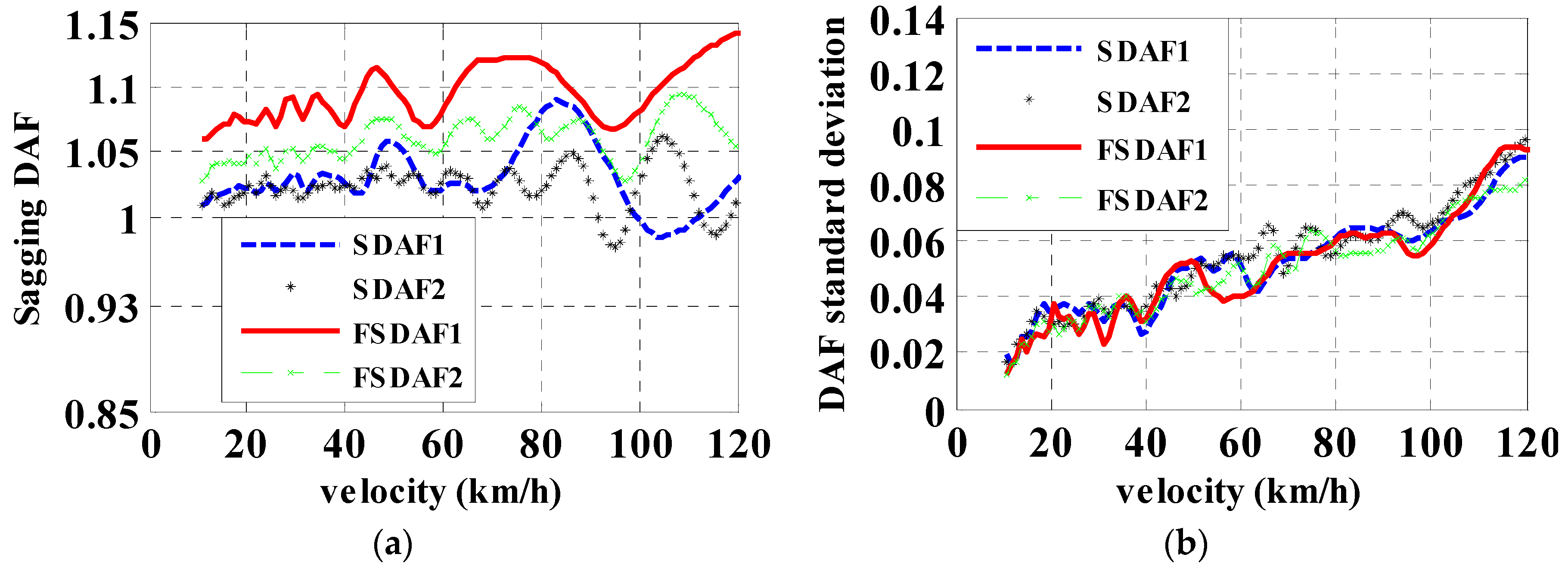
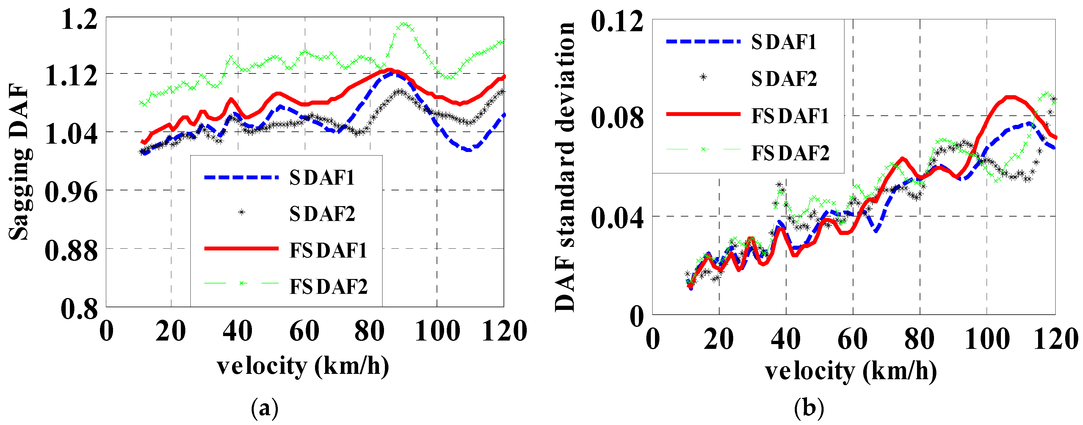
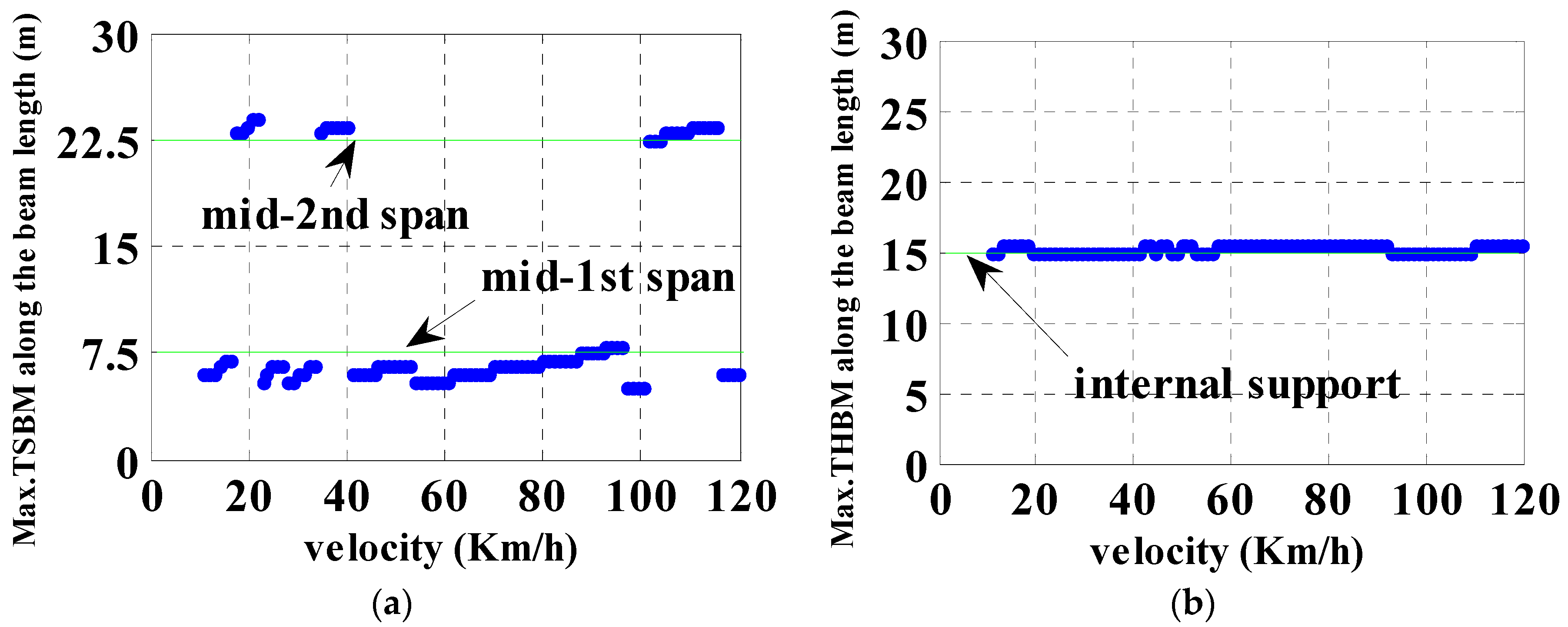
3.2.1. DAF of Sagging Moments
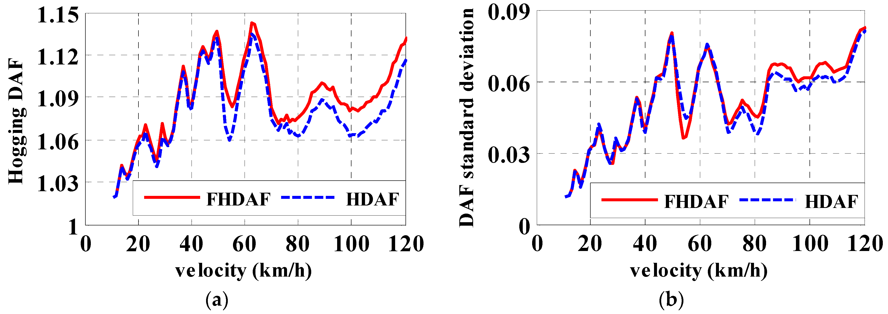
3.2.2. DAF of Hogging Moments
4. Discussion
5. Summary and Conclusions
Author Contributions
Acknowledgments
Conflicts of Interest
References
- Frýba, L. Vibration of Solids and Structures Under Moving Loads; Noordhoff International Publishing: Groningen, The Netherlands, 1972. [Google Scholar] [CrossRef]
- Cantieni, R. Dynamic Load Testing of Highway Bridges; Technical Report; Transportation Research Board: Washington, DC, USA, 1984; Volume 950, pp. 141–148. Available online: http://onlinepubs.trb.org/Onlinepubs/trr/1984/950/950v2-015.pdf (accessed on 18 May 2018).
- Green, M.F.; Cebon, D.; Cole, D.J. Effects of vehicle suspension design on dynamics of highway bridges. J. Struct. Eng. 1995, 121, 272–282. [Google Scholar] [CrossRef]
- Yang, Y.B.; Liao, S.S.; Lin, B.H. Impact formulas for vehicles moving over simple and continuous beams. J. Struct. Eng. 1995, 121, 1644–1650. [Google Scholar] [CrossRef]
- Chan, T.H.; O’Connor, C. Vehicle model for highway bridge impact. J. Struct. Eng. 1990, 116, 1772–1793. [Google Scholar] [CrossRef]
- Ichikawa, M.; Miyakawa, Y.; Matsuda, A. Vibration analysis of the continuous beam subjected to a moving mass. J. Sound Vib. 2000, 230, 493–506. [Google Scholar] [CrossRef]
- Brady, S.P.; O’Brien, E.J. Effect of vehicle velocity on the dynamic amplification of two vehicles crossing a simply supported bridge. J. Bridge Eng. 2006, 11, 250–256. [Google Scholar] [CrossRef]
- Miguel, L.F.F.; Lopez, R.H.; Torii, A.J.; Miguel, L.F.F.; Beck, A.T. Robust design optimization of TMDs in vehicle–bridge coupled vibration problems. Eng. Struct. 2016, 126, 703–711. [Google Scholar] [CrossRef]
- Paultre, P.; Chaallal, O.; Proulx, J. Bridge dynamic and dynamic amplification factors—A review of analytical and experimental findings. Can. J. Civ. Eng. 1992, 19, 260–278. [Google Scholar] [CrossRef]
- Deng, L.; Yu, Y.; Zou, Q.; Cai, C.S. State-of-the-Art review of dynamic impact factors of highway bridges. J. Bridge Eng. 2014, 20, 04014080. [Google Scholar] [CrossRef]
- Chu, V.T.H. A Self-Learning Manual Mastering Different Fields of Civil Engineering Works (VC-Q&A Method). 2010. Available online: http://civil808.com/article/ac/3428 (accessed on 18 May 2018).
- Yang, Y.B.; Yau, J.D.; Wu, Y.S. Vehicle Bridge Interaction Dynamics with Application to High-Speed Railways; World Scientific Publishing Co. Pte. Ltd.: Singapore, 2004. [Google Scholar] [CrossRef]
- Rezaiguia, A.; Ouelaa, N.; Laefer, D.F.F.; Guenfoud, S. Dynamic amplification of a multi-span, continuous orthotropic bridge deck under vehicular movement. Eng. Struct. 2015, 100, 718–730. [Google Scholar] [CrossRef]
- Cantero, D.; González, A.; O’Brien, E.J. Maximum dynamic stress on bridges traversed by moving loads. Proc. ICE Bridge Eng. 2009, 162, 75–85. [Google Scholar] [CrossRef]
- Mohammed, O.; Cantero, D.; González, A.; Al-Sabah, S. Dynamic amplification factor of continuous versus simply supported bridges due to the action of a moving load. In Proceedings of the Civil Engineering Research in Ireland (CERI 2014), Queen’s University, Belfast, Ireland, 28–29 August 2014; Available online: http://hdl.handle.net/10197/6582 (accessed on 18 May 2018).
- González, A. Vehicle-bridge dynamic interaction using finite element modelling. In Finite Element Analysis; Moratal, D., Ed.; Sciyo: Rijeka, Croatia, 2010; pp. 637–662. Available online: https://www.intechopen.com/books/finite-element-analysis/vehicle-bridge-dynamic-interaction-using-finite-element-modelling (accessed on 18 May 2018).
- O’Brien, E.; González, A.; McGetrick, P. A drive-by inspection system via vehicle moving force identification. Smart Struct. Syst. 2012, 5, 821–848. [Google Scholar] [CrossRef]
- Keenahan, J.; O’Brien, E.J.; McGetrick, P.J.; González, A. The use of a dynamic truck-trailer drive-by system to monitor bridge damping. Struct. Health Monit. 2014, 13, 143–157. [Google Scholar] [CrossRef]
- McGetrick, P.; Kim, C.-W.; González, A.; O’Brien, E. Experimental validation of a drive-by stiffness identification method for bridge monitoring. Struct. Health Monit. 2015, 14, 317–331. [Google Scholar] [CrossRef]
- European Committee for Standardization (CEN). Eurocode 1: Actions on Structures, Part 2: Traffic Loads on Bridges (EN 1991-2:2003); European Committee for Standardization: Brussels, Belgium, 2003. [Google Scholar]
- Cebon, D. Handbook of Vehicle-Road Interaction; Swets & Zeitlinger: Lisse, The Netherlands, 1999; Available online: https://www.crcpress.com/Handbook-of-Vehicle-Road-Interaction/Cebon/p/book/9789026515545 (accessed on 18 May 2018).
- Harris, N.K.; O’Brien, E.J.; González, A. Reduction of bridge dynamic amplification through adjustment of vehicle suspension damping. J. Sound Vib. 2007, 302, 471–485. [Google Scholar] [CrossRef]
- Li, Y.C. Factors Affecting the Dynamic Interaction of Bridges and Vehicle Loads. Ph.D. Thesis, Department of Civil Engineering, University College Dublin, Dublin, Ireland, 2006. [Google Scholar]
- Clough, R.W.; Penzien, J. Dynamics of Structures; McGraw-Hill: New York, NY, USA, 1993. [Google Scholar] [CrossRef]
- Wang, T.; Huang, D.; Shahawy, M. Dynamic response of multigirder bridges. J. Struct. Eng. 1992, 118, 2222–2238. [Google Scholar] [CrossRef]
- Huang, D.Z.; Wang, T.L.; Shahawy, M. Dynamic behavior of horizontally curved I-girder bridges. Comput. Struct. 1995, 57, 703–714. [Google Scholar] [CrossRef]
- Kim, C.-W.; Kawatani, M.; Kwon, Y.-R. Impact coefficient of reinforced concrete slab on a steel girder bridge. Eng. Struct. 2007, 29, 576–590. [Google Scholar] [CrossRef]
- International Organization for Standardization (ISO). Mechanical Vibration—Road Surface Profiles—Reporting of Measured Data; ISO8608 (BS7853:1996); International Organization for Standardization: Geneva, Switzerland, 1995. [Google Scholar]
- Cebon, D.; Newland, D.E. Artificial generation of road surface topography by the inverse F.F.T. method. Veh. Syst. Dyn. 1983, 12, 160–165. [Google Scholar] [CrossRef]
- Agostinacchio, M.; Ciampa, D.; Olita, S. The vibrations induced by surface irregularities in road pavements—A Matlab® approach. Eur. Trans. Res Rev. 2013, 6, 267–275. [Google Scholar] [CrossRef]
- Sayers, M.W.; Karamihas, S.M. Interpretation of Road Roughness Profile Data—Final Report; University of Michigan Transportation Research Institute (UMTRI): Ann Arbor, MI, USA, 1996. [Google Scholar]
- MATLAB, version r 2014 a; The MathWorks: Natick, MA, USA, 2014; Available online: https://aj-hub.ucd.ie/ (accessed on 18 May 2018).
- Tedesco, J.W.; McDougal, W.G.; Ross, C.A. Structural Dynamics: Theory and Applications; Addison-Wesley Longman: Petaluma, CA, USA, 1999; ISBN-10 0673980529. [Google Scholar]




| Property | Symbol | Value | Unit |
|---|---|---|---|
| Body Mass | ms | 26,750 | kg |
| Axle1 mass | mu1 | 700 | kg |
| Axle2 mass | mu2 | 1100 | kg |
| Suspension stiffness | Ks1 | 4 × 10⁵ | N m−1 |
| Ks2 | 10 × 105 | N m−1 | |
| Suspension Damping | Cs1 | 10 × 103 | Ns m−1 |
| Cs2 | 20 × 103 | Ns m−1 | |
| Tire Stiffness | Kt1 | 1.75 × 10⁶ | N m−1 |
| Kt2 | 3.5 × 10⁶ | N m−1 | |
| Tire Damping | Ct1 | 3 × 10³ | Ns m−1 |
| Ct2 | 5 × 10³ | Ns m−1 | |
| Moment of Inertia | Is | 154,320 | kg m2 |
| Body bounce frequency | fbounce | 0.86 | Hz |
| Body pitch frequency | fpitch | 1.02 | Hz |
| Axle1 hop frequency | faxle1 | 8.83 | Hz |
| Axle2 hop frequency | faxle2 | 10.19 | Hz |
| Property | Symbol | Value | Unit |
|---|---|---|---|
| Body Mass 1 | ms1 | 25,200 | kg |
| Body Mass 2 | ms2 | 30,700 | kg |
| Axle1 mass | mu1 | 700 | kg |
| Axle2 mass | mu2 | 1100 | kg |
| Axle3 mass | mu3 | 1100 | kg |
| Axle4 mass | mu4 | 1100 | kg |
| Axle5 mass | mu5 | 1100 | kg |
| Suspension stiffness | Ks1 | 4 × 10⁵ | N m−1 |
| Ks2, Ks3, Ks4, Ks5 | 10 × 105 | N m−1 | |
| Suspension Damping | Cs1 | 10 × 103 | Ns m−1 |
| Cs2, Cs3, Cs4, Cs5 | 20 × 103 | Ns m−1 | |
| Tire Stiffness | Kt1 | 1.75 × 10⁶ | N m−1 |
| Kt2, Kt3, Kt4, Kt5 | 3.5 × 10⁶ | N m−1 | |
| Tire Damping | Ct1 | 3 × 10³ | Ns m−1 |
| Ct2, Ct3, Ct4, Ct5 | 5 × 10³ | Ns m−1 | |
| Moment of Inertia 1 | Is1 | 86,410 | kg m2 |
| Moment of Inertia 2 | Is2 | 112,440 | kg m2 |
| Body 1 bounce frequency | f1bounce | 1.56 | Hz |
| Body 1 pitch frequency | f1pitch | 2.39 | Hz |
| Axle1 hop frequency | faxle1 | 9.97 | Hz |
| Axle2 hop frequency | faxle2 | 8.77 | Hz |
| Body 2 bounce frequency | f2bounce | 2.12 | Hz |
| Body 2 pitch frequency | f2pitch | 2.33 | Hz |
| Axle3 hop frequency | faxle3 | 10.03 | Hz |
| Axle4 hop frequency | faxle4 | 10.15 | Hz |
| Axle5 hop frequency | faxle5 | 10.17 | Hz |
| Vehicle Type | Class Type of Road Surface | |||||||||||
|---|---|---|---|---|---|---|---|---|---|---|---|---|
| Class “A” | Class “B” | |||||||||||
| DAF | FDAF | DAF | FDAF | |||||||||
| µ | σ | Velocity km/h | µ | σ | Velocity km/h | µ | σ | Velocity km/h | µ | σ | Velocity km/h | |
| 2-axle | 1.12 | 0.036 | 85.32 | 1.12 | 0.036 | 85.32 | 1.12 | 0.065 | 85.32 | 1.12 | 0.065 | 85.32 |
| 5-axle | 1.12 | 0.04 | 93.6 | 1.14 | 0.04 | 91.8 | 1.14 | 0.07 | 91.8 | 1.17 | 0.07 | 92.88 |
| Vehicle Type | SDAF1 | SDAF2 | FSDAF1 | FSDAF2 | ||||||||
|---|---|---|---|---|---|---|---|---|---|---|---|---|
| µ | σ | Velocity km/h | µ | σ | Velocity km/h | µ | σ | Velocity km/h | µ | σ | Velocity km/h | |
| 2-axle | 1.1 | 0.04 | 83.11 | 1.08 | 0.04 | 105.8 | 1.13 | 0.06 | 120 | 1.1 | 0.04 | 108 |
| 5-axle | 1.09 | 0.03 | 85.32 | 1.05 | 0.04 | 101.5 | 1.1 | 0.03 | 84.24 | 1.14 | 0.04 | 90.72 |
| Vehicle Type | SDAF1 | SDAF2 | FSDAF1 | FSDAF2 | ||||||||
|---|---|---|---|---|---|---|---|---|---|---|---|---|
| µ | σ | Velocity km/h | µ | σ | Velocity km/h | µ | σ | Velocity km/h | µ | σ | Velocity km/h | |
| 2-axle | 1.09 | 0.07 | 84.24 | 1.06 | 0.07 | 104.8 | 1.14 | 0.09 | 120 | 1.09 | 0.07 | 108 |
| 5-axle | 1.12 | 0.06 | 87.48 | 1.1 | 0.07 | 88.56 | 1.12 | 0.06 | 85.32 | 1.19 | 0.07 | 90.72 |
| Vehicle Type | Class “A” | Class “B” | ||||||||||
|---|---|---|---|---|---|---|---|---|---|---|---|---|
| HDAF | FHDAF | HDAF | FHDAF | |||||||||
| µ | σ | Velocity km/h | µ | σ | Velocity km/h | µ | σ | Velocity km/h | µ | σ | Velocity km/h | |
| 2-axle | 1.11 | 0.06 | 120 | 1.15 | 0.07 | 120 | 1.2 | 0.11 | 120 | 1.25 | 0.11 | 120 |
| 5-axle | 1.06 | 0.03 | 36.76 | 1.06 | 36.72 | 0.03 | 1.13 | 0.07 | 62.64 | 1.14 | 0.07 | 62.64 |
© 2018 by the authors. Licensee MDPI, Basel, Switzerland. This article is an open access article distributed under the terms and conditions of the Creative Commons Attribution (CC BY) license (http://creativecommons.org/licenses/by/4.0/).
Share and Cite
González, A.; Mohammed, O. Dynamic Amplification Factor of Continuous versus Simply Supported Bridges Due to the Action of a Moving Vehicle. Infrastructures 2018, 3, 12. https://doi.org/10.3390/infrastructures3020012
González A, Mohammed O. Dynamic Amplification Factor of Continuous versus Simply Supported Bridges Due to the Action of a Moving Vehicle. Infrastructures. 2018; 3(2):12. https://doi.org/10.3390/infrastructures3020012
Chicago/Turabian StyleGonzález, Arturo, and Omar Mohammed. 2018. "Dynamic Amplification Factor of Continuous versus Simply Supported Bridges Due to the Action of a Moving Vehicle" Infrastructures 3, no. 2: 12. https://doi.org/10.3390/infrastructures3020012
APA StyleGonzález, A., & Mohammed, O. (2018). Dynamic Amplification Factor of Continuous versus Simply Supported Bridges Due to the Action of a Moving Vehicle. Infrastructures, 3(2), 12. https://doi.org/10.3390/infrastructures3020012


