Review

Composites for Timber-Replacement Bearers in Railway Switches and Crossings

1
School of Engineering, The University of Birmingham, Birmingham B15 2TT, UK
2
Railway Engineering Institute, China Academy of Railway Sciences, Beijing 100081, China
3
Railway Engineering Department, Nippon Koei, Tokyo 102-8539, Japan
*
Author to whom correspondence should be addressed.
Infrastructures 2017, 2(4), 13; https://doi.org/10.3390/infrastructures2040013
Submission received: 25 August 2017 / Revised: 27 September 2017 / Accepted: 6 October 2017 / Published: 9 October 2017
(This article belongs to the Special Issue Railway Infrastructure Engineering)

Abstract

:
Recent developments in composite materials have resulted in their pilot adoption in railway industry, such as ‘fibre-reinforced foamed urethane (FFU)’, ‘geopolymer concrete’, ‘recycled polymer’, and ‘CarbonLoc composite’. Railway track support systems are critical for safe and reliable operations of railway tracks. There are two types of support structures, which can be designed to be either a slab or a cluster of discrete bearers or sleepers. The choice of turnout support system depends on asset management strategy of the rail operators or maintainers. The aim of this paper is to present the criteria, fundamental and multi-disciplinary issues for the design and practical selection of composite materials in railway turnout systems. As a case study, a full-scale trial to investigate in-situ behaviours of a turnout grillage system using an alternative material, ‘fibre-reinforced foamed urethane (FFU)’ bearers, is presented. Influences of the composite bearers on track geometry (recorded by track inspection vehicle ‘AK Car’ and based on survey data), track settlement, track dynamics, and acoustic characteristics are highlighted in this paper. Comparative studies of composite materials for railway track applications are reviewed and presented in order to improve material design process. This state-of-the-art review paper will also focus on practicality and environmental risks of composite components in railway built environments. It embraces the requirement considerations of new materials for use as safety-critical track elements.

1. Introduction

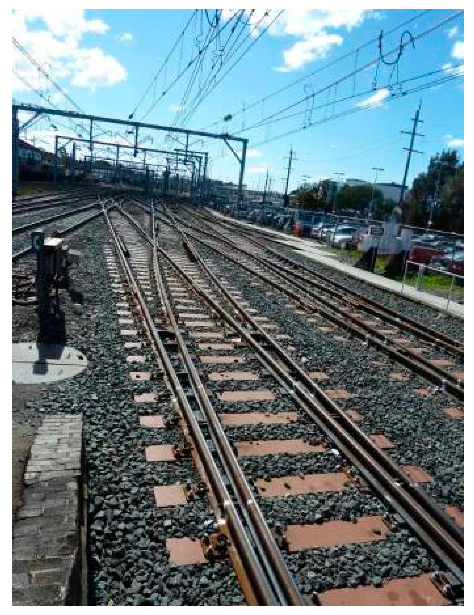
Railway urban turnout is a special track system used to divert a train from a particular direction or a particular track onto other directions or other tracks. It is a structural grillage system that consists of steel rails, points (or called ‘switches’), crossings (special track components), steel plates, rubber pads, insulators, fasteners, screw spikes, beam bearers (either timber, polymer, steel, or concrete), ballast, and formation, as shown in Figure 1 [1]. Traditional turnout structures were generally supported by timber bearers. The timber bearers allow the steelwork to be mounted directly on steel plates that are spiked or screwed into the bearers. Timber, steel, and concrete are common materials, which have had long history records of usage in tracks over a decade. Timber has an excellent damping coefficient, whilst concrete and steel tend to have almost no damping coefficient [2,3,4,5]. Concrete has proven to be an excellent counterpart to improve track and turnout stability—laterally, longitudinally, and vertically [6,7]. Recent studies also show that steel bearers perform well in a short term, but have higher turnout settlement and ballast breakage over the long term [8,9].
This paper presents the criteria and fundamental of bearer design for a grillage turnout system. The materials’ characteristics are illustrated to provide an in-depth understanding into the static and dynamic performances of a turnout over its life cycle, as well as the potential benefits of new materials in reducing the depth of bearers while maintaining stability. It demonstrates a case study of monitoring the static and dynamic in-situ performance of the alternative fibre-reinforced foamed urethane (FFU) material as a like-for-like replacement of timber bearers. This study involves the inspection, turnout settlement monitoring, geometry data analysis, train-track interaction, sound pressure, and vibration measurements of the double slips, and benchmarking with other field data [10,11,12,13].

2. Materials and Methods

It is well known that traditional turnout generally imparts high impact forces on to structural members because of its blunt geometry and mechanical connections between closure rails and switch rails (i.e., heel-block joints). Although a new method of geometrical design has been adopted for tangential turnouts, the transfer zone at a crossing nose in complex turnout system still imposes high-frequency forces to track components. Under static and high-intensity impact loading conditions, timber bearers have a long proven record that they can provide firmed support to such turnouts. The structural timber bearers in turnout systems are usually in Strength Group 1 [3] and the typical timber species are tabulated in Table 1. Based on the strength, Table 2 displays the design dimensions of timber bearers in a variety of railway turnouts with nominal design spacing of 600 mm (or between 500 mm and 700 mm) [3]. It is important to note that timber bearers for supporting points and crossing structures may be designed using the beam on elastic foundation analysis (similar to traditional railway sleepers) but one must take into account additional factors:
  • Extra length of timber bearers in comparison with standard sleepers;
  • Centrifugal forces through curved pairs of rails;
  • Forces and bending moments induced from points, motors, and other signaling equipment;
  • Impact forces induced by wheel-rail interaction;
  • Mechanical rail joints (maximum spacing of bearers is 600 mm);
Currently, the procurement of high-quality long timber bearers used in complex turnout systems is very difficult for either construction or renewal processes in Australia. Problems with long timber turnout bearers (>4 m) include localised weakness, large deformation, warping, or unstable dimensions that can easily cause obstructions during the turnout assembly resulting in a poor geometry of new turnouts. Then, the wheel/rail interaction (see Figure 2) over such poor short-pitch irregularity induces impact force and vibration that exacerbates the condition and undermines the service life of turnout components and the integrity of turnout system as a whole [10].
In present days, the difficulty to seek out high-quality timbers has led to two possible alternatives in practice: first, to use the concrete long bearers with splice plates; second, to use the alternative material (i.e., Fibre-reinforced Foamed Urethane or so-called FFU; composite materials, plastic rubber materials, etc.) with the similar characteristics as a timber. A critical review has enabled a field trial of FFU material in switches and crossings because of its high-impact attenuation, high damping property, high UV resistance, and long service life. As a result, the complex turnout junction with aged timber bearers at Hornsby, NSW, Australia was renewed in 2010 using FFU material. There were five stages of construction: note that the first turnout was constructed in October 2010 and the double slips were installed in late June 2011. Also, due to the light-weight of FFU bearers, a special arrangement was designed to maintain lateral stability to the turnouts [3].
Fundamental engineering properties of the FFU material are tabulated in Table 3 [11,12,13]. The material design for turnout sleeper/bearer application usually considers flexural bending moments resulted from vertical train-track interaction as shown in Equations (1)–(3). In railway operational practice, the dynamic vertical load (P2) by a wheel of train wagon is usually controlled or limited to 230 kN force by appropriate maintenance schemes [3]. Note that this value does not take into account any high-frequency impact forces imposed on top of the quasi-static design load (P2). The high-frequency impact force, or so-called P1, often causes rapid deterioration of crossings, fastening systems, and low-damping concrete bearers. Naturally, the dynamic content of P1 is filtered by material damping characteristics (i.e., in fastening system, in timber or in FFU).
In a calculation of P2 force, the track damping Ct is normally negligible. For plain tracks, it is commonly found that the track mass is relatively low in comparison with the wheel set mass and is then neglected. In contrast, for a turnout crossing, the track mass tends to be of significance and it cannot be neglected. Jenkins et al. [14] has proposed a formula for estimating a dynamic P2 force as follows:
P 2 = P 0 + 2 α v [ M u M u + M t ] 1 2 [ 1 π C t 4 K t ( M u + M t ) ] [ K t M u ] 1 2
where P2 = Dynamic vertical force (kN)
  • P0 = Vehicle static wheel load (kN)
  • Mu = Vehicle unstrung mass per wheel (kg)
  •  2α = Total joint angle or equivalent dip angle (rad)
  • v = Vehicle velocity (m/s)
  • Kt = Equivalent track stiffness (MN/m)
  • Ct = Equivalent track damping (kNs/m)
  • Mt = Equivalent track mass (kg)
The typical characteristic FFU compressive strength is 58 MPa (note that sleepers/bearers’ concrete compressive strength after 28 days is about 50 MPa). It was evidenced that the 30-year FFU material retained the compressive strength of around 55 MPa. The design flexural (σm) and shear (σs) stresses can be obtained using Equations (1) and (2), respectively:
σm = My/I
σs = P/A
where M is design bending moment, P is the design shear force, y is the fibre arm length, I is the moment of inertia, and A is the area of the beam cross section. Table 4 shows basic engineering properties of two similar composite materials. As the above table shows the strength, stiffness, and fire performance of Carbonloc material significantly outperforms that of Axion [15].
A practical example in the real world can be illustrated by re-considering or re-designing the turnout sleepers under services. For narrow gauge turnout sleepers (25 tonne axle load) [3]: Ultimate BM: 19 kNm, Stiffness: 25 × 1010 MPa, Shear: 158 kN.
Assuming a safety factor of 2.5 for both products, an Axiom bearer would require a depth of 215 mm to comply with these forces and a Carbonloc bearer would need a depth of 140 mm [3].

3. Materials Sensitivity

Since the beginning of the history of railways, timber is the main and most used material for sleepers. Due to a scarcity of noble wood, the high price, and increased maintenance requirements, the need for other materials has grown [16]. Concrete and steel have emerged as options to new lines. Mechanical advantages and lower susceptibility to wear are the major appealing features presented by steel and concrete sleepers. However, they do not have mechanical properties compatible with the timber sleeper, making ineffective the replacement and co-operation. Therefore new timber sleepers still are a more favourable option in a short term to replace the damaged sleepers in existing lines [17]. More recently, environmental concerns and the search for an alternative able to reproduce behaviour more comparable to timber have increased the research on plastic/polymer and fibre composite sleepers [17].

3.1. Timber

A major advantage of timber sleepers is their flexibility, which results in a great ability to resist vibrations deriving from dynamic loads in railway track system [18,19]. The ease of handling, replacement, and adaptation to track systems are other benefits of this material. According to Manalo [17], timber sleepers can be suited to all types of railway track. Additionally, the electrical isolation provided by a timber sleeper is valuable to the signaling system and only plastic or fibre composites sleepers could also match this characteristic. Esveld [20] arranged timber sleepers into two categories: softwood (e.g., pinewood) and hardwood (e.g., beech, oak, tropical tree). Hardwood timber is the most common sleeper material in railway lines through the world. Its advantages over the softwood timber are its greatest strength and durability [20]. However, over the years the hardwood timber has become increasingly expensive, its availability is reducing and those which are still available no longer have the same quality [21].
Although more resistant to fungal decay, softwood sleepers offer less resistance to end splitting, gauge spreading, and spike hole enlargement than hardwood sleepers. Furthermore, they are less effective in transmitting loads to the ballast section as hardwood sleepers. Due to this difference in loads transmission hardwood sleepers and softwood sleepers should not be used together on the railway track [20,21]. Due to diverse environmental conditions, woods are susceptible to severe degradation due to the attack of various organisms. The resistance of untreated wood to fungal decay in service above ground is low, affecting its durability. Non-durable timbers generally require preservative treatment if they are to be used in exposed conditions, adding significantly to their cost. Moreover, there is growing concern regarding the use and disposal of this impregnated material for their consequences for the environment [22].

3.2. Concrete

After the Second World War, the use of concrete sleepers had a significant increase in Britain and Europe due to the timber scarcity. Progressively, reinforced and pre-stressed concrete sleepers have replaced timber and steel sleepers [23] due to their prolonged life cycle and reduced maintenance costs [24]. Two varieties of concrete sleepers are offered in the market accordingly to Esveld [20]: reinforced twin-block and prestressed monoblock sleepers. The twin-block consists of two blocks of reinforced concrete connected by a steel bar or stiff steel beam. While monoblock sleepers consist of one prestressing reinforced concrete beam [25]. The monoblock concrete sleeper is the type that has greater acceptance in the market due to its superior durability in the face of unfavourable environments. Another advantage observed is the resistance to twist, failure commonly presented by twin block concrete sleepers. Because of this usual failure the installing process of this type of sleeper requires greater care, making it more difficult to handle and contributing to a lower acceptance, even with their reduced weight compared to monoblock sleepers.
Concrete is known for its high resistance to compression, on the other hand, it presents weakness when it comes to tension. Due to this characteristic, monoblock concrete sleepers use the technique of prestressing to withstand the dynamic loads arising from the passage of the train. This procedure consists of the tensioning of steel rods before or after the concrete is moulded. Prestressed concrete presents increased ductility, higher flexural strength and resistance to cracking [18]. The stability and slight position movement offered by prestressed concrete sleepers because of its heavy weight meant that it had a significant acceptance in high-speed lines. At the same time, the great weight reduces mobility, making it difficult to transport and being necessary specific equipment for installation which increases the costs of concrete sleepers. One of the causes of this high weight is a need for greater thicknesses in comparison to timber sleepers with the aim of reducing dynamic tension at the bottom fibre [26].
Costs for producing and maintaining prestressed concrete sleepers are considerably elevated. Their initial costs are about twice that the hardwood timber sleepers [16]. However, due to its high durability and specifications that comply with the solicitations of a railway system, prestressed concrete sleepers can be currently considered as the best cost-benefit to serve ballasted railway lines [20] and the preferred sleeper to railway tracks nowadays [21].

3.3. Steel

With a typical lifecycle of about 50 years, steel sleepers emerged as a first option to substitute timber sleepers around the 1880s [27]. A steel sleeper presents higher mechanical strength, can be lighter than timber and are easy to handle, they can even be operated manually. However, their use is usually limited to lightly traveled tracks [28]. An excellent gauge restrains and increased lateral resistance due to its geometry are other technical advantages presented by a steel sleeper. Additionally, damaged sleepers also have commercial value [27], since the steel can be recycled several times and reused in the railway industry [27]. In the search for further improving the characteristics of steel sleepers, the traditional orthogonal sleepers have been replaced by Y-steel-sleepers (Figure 3). The development of this new model provided a further reduction in weight of steel sleepers and gain of resistance against cross movements due to the amount of accumulated ballast in its central part as a consequence of its design similar to the letter Y [28].
A significant disadvantage of steel sleepers is the due to the difficulty to achieve a reasonable packing with ballast, requiring special care during the installation process and tamping [29]. Other problems such as fear of corrosion, fatigue cracking in the fastening holes caused by moving trains, high electrical conductivity (that can lead to problems with track circuit signaling), and excessive noise also contribute to the inferior popularity of steel sleepers [27]. However, the greatest restriction of the use of steel as a material for the production of sleepers is its excessive value [29].

3.4. Plastic, Polymer, and Composites

Material scarcity, as well as environmental concern, motivates researchers regarding new materials capable of satisfying the railway system requirements. Develop a structure that is economically competitive and that meets the needs of the industry is a major challenge of civil engineering. There is a constant search for a material that is durable, reasonably easy to produce and maintain, have attractive costs, and meets the expected requests effectively [30]. A key concern in the railway industry is the replacement of damaged and deteriorated sleepers in existing tracks [30]. The importance of the development of the polymer and composite sleepers is due to the capacity to design it to mimic the timber behaviour, which cannot be achieved with concrete and steel sleepers. A factor of extreme importance for the maintenance of timber tracks [31]. Moreover, polymer and composite sleepers require low to almost no maintenance, thus this improved life-cycle makes them a suitable alternative for areas that are harder to maintain such as tunnels, bridges, and turnouts. Another advantage is its sustainable approach, what makes them be notable in the face of the constant increase of concern over the existing environment in the current industry [32].
Many studies are given in the area of polymers and composites as material for the manufacture of sleepers. A composite material is manufactured from two or more distinct materials combined to achieve characteristics not found in those who compose it [30]. There are several efforts towards improving the characteristics of the materials already used in the railway track engineering (wood, steel, and concrete) as applied to the polymer by itself or composite polymers, using mainly fibres [25]. A fibre composites system characteristically consists of a lightweight polymer matrix with strong fibres inserted into it [25]. The fibre reinforcement sustains the load due to its high strength and can be applied as reinforcement only in the longitudinal direction or longitudinal and transverse directions.
Accordantly with Manalo [25], fibre composites could be perfectly suitable for the production of railway sleepers. These composite can be engineered based on the required structural applications and manufactured with almost the same dimensions and weight to that of hardwood timber. Additionally, fibre composites railway sleepers offer high strength, are light, and present a longer lifecycle, reducing maintenance costs. Moreover, fibre composites are easy to handle, they can be drilled in situ for the connection of the fastener system and inserted under the track as timber sleepers. Another appeal of polymer and composites sleepers is the environmental question. There are many efforts in study polymers produced from recycled plastic. Since 1990, several U.S. companies and institutions has shown interest in the production of sleepers from recycled plastic. According to Lampo [33], the recycled plastic material can help reduce emissions of greenhouse gas, save millions of trees, reduce chemical contamination due to the preservatives present in timber sleepers, and also add commercial value to a large amount of waste. Economically most fibre composite sleeper developments still have disadvantages compared to traditional sleeper materials due to higher initial costs [34]. Companies such as Carbonloc Pty Ltd., University of Southern Queensland (USQ) in Toowoomba, Australia, has devoted researchers regarding the shape optimization of polymer sleepers based on the load and support pattern and reducing considerably the volume of polymer needed while assure that it still achieve all the proprieties needed to cope with the railway solicitations [30].

4. Review of a Practical Case Study

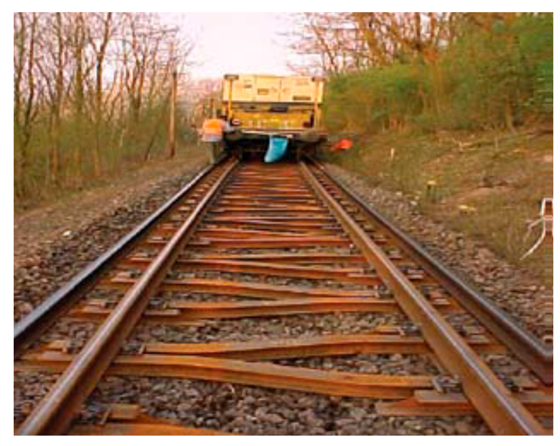
A pilot test was carried out under revenue services in a trial site at Hornsby, New South Wales [1,2,3]. Because of the complexity of the junction, the sets of urban turnouts were constructed in different stages and timeframes. The junction is comprised of five sets of turnouts, a set of single slips, and a set of double slips [24]. A key benefit of fibre-reinforced urethane (FFU) usage is to permit such construction stages, of those four stages (Figure 4).
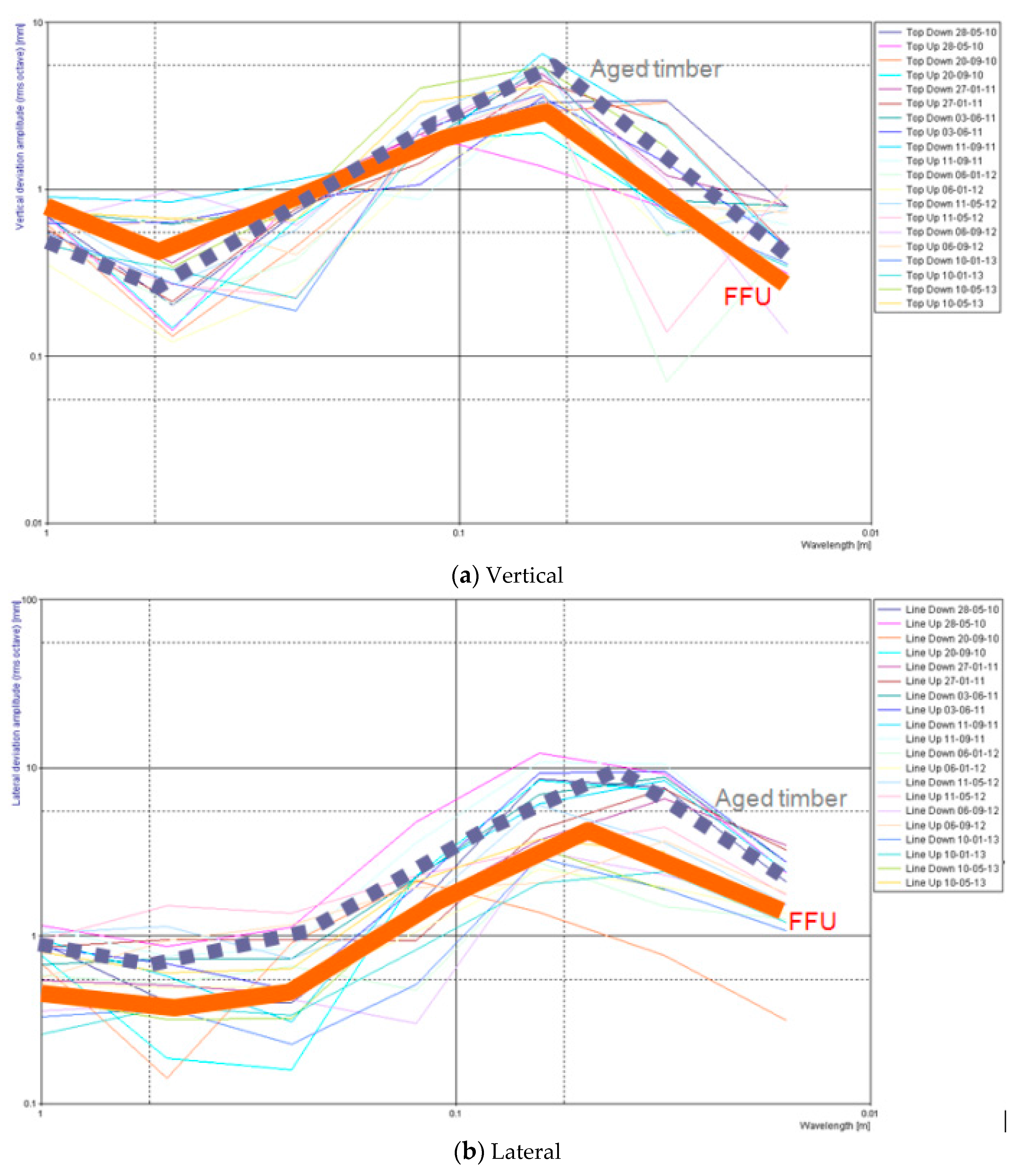
Track geometry data were collected (wheelset displacements over incremental time series) and then, Fourier analyses (using FFT: Fast Fourier Transform) have been carried out using the zoom-in 50 m section of the double slip from 33.970 km to 34.020 km. The analyses display the track geometry changes with respect to wavelength as demonstrated in Figure 5.
The results also show that the vertical deviation amplitude of the turnout with FFU bearers is higher than the top of timber at the low frequency band (note that FFU’s elastic modulus is lesser than F22 hardwood timber’s). Figure 5 confirms that FFU material has slightly lesser static stiffness compared with hard wood timbers. On the other hand, at the wavelength of about 60 mm (associated with high-frequency turnout impact), the peak top deviation amplitude of FFU bearers is lesser than the top of timber. This is because new FFU bearers have higher damping than aged timber bearers and they could then perform better under high frequency vibrations.
In addition, the overall lateral deviation (line 10 m cord) of the turnouts with FFU bearers tends to behave better laterally, in comparison with ones supported by poor timbers. Especially at the low wavelength range (high frequency band), the FFU lateral deformation performance on average is less than the turnout with aged timbers.

5. Carbon Footprint

The construction industry is one of the greatest consumers of raw material and energy, as well as a major generator of environmental pollution [35]. Consequently, the choice of materials is a subject of ongoing debate. Considering railway engineering, several concerns arise when discussing manufacture, preservative treatment, and disposal of damaged and deteriorated sleepers. The manufacturing process of railway sleeper can be associated with substantial environmental impacts. Resource required to the production of sleepers as energy and material are responsible for a large greenhouse gas emission [36]. Materials such as concrete and steel consume a significant amount of energy during production and could dispense respectively 10–200 times more carbon dioxide into the atmosphere than hardwood timber sleepers [20]. Moreover, gases are also generated during the transportation and installation of sleepers and a great quantity of waste is resulted, mostly from the harvesting of timber [20]. However, during the service life, the decay of timber sleepers continues resulting in impacts to the environment. This is due to the fact that during their growth, trees keep in its structure carbon that is absorbed from the atmosphere and once timber has been cropped it progressively liberates carbon dioxide back to the environment. Then this emission is extending even after the disposal of these sleepers until the end of its decomposition. As a comparison parameter, Crawford [36] founds that emissions related to the service life of timber sleepers can be up to six times greater than the emissions associated with reinforced concrete sleepers. Another concern related to using and discarding of timber sleepers comes from the practice of chemically impregnating them with creosote to preserves it from biological deterioration [37].
Despite being widely used, toxic substances are present in these chemical preservatives which do not easily decompose in nature and are volatiles [35]. So they are gradually released into the air during the life cycle of the sleeper and may cause environmental pollution and present risks to human health. On the other hand, plastic sleeper, when made from recycled plastic, can be beneficial to the environment. Its production not only saves the use of other materials but also provides functionality to a considerable amount of waste as well as attaching commercial value to a material that would be discarded [34]. Though, the use of non-recycled plastic for manufacturing sleepers generates concerns mainly because of some plastics being a by-product of oil, in addition to being non-biodegradable. Furthermore, the service life of the sleepers has a great impact on its sustainability since it determines the demand of material over the years, and also the amount of discarded units, which generates great impact especially on the use of land. The expected service lives of the different types of sleepers are listed on the Table 5.

6. Georisk

Railway track substructure is expected to resist the static and dynamic loads that are generated by the passage of moving trains. Additionally, the cyclic characteristic of these loads has a great influence on the track long-term behaviour. A major challenge when it comes to investigating the behaviour of the substructure arises due to the variability of the substructure component’s proprieties. Attributable to this characteristic, the analysis of dynamic and repeated loading becomes more demanding due to the non-linear stiffness presented by granular materials [5]. Understand how the substructure components react when subjected to these loads, how the loads are transferred from the sleeper to the track substructure and how the interaction between the components of the superstructure and substructure occurs is extremely important to the design, efficient operation, and security of railway roads [38]. Table 6 illustrates georisks under climate uncertainties.

7. Systems Requirements

Both the sleepers in the main line and the bearers in switches and crossings are the safety-critical components for railway applications [39]. As the essential part of the rail track systems, the main requirements of sleepers and bearers include providing an anchorage for the fastening system, keeping the stability of railway track, and transmission vertical, lateral and longitudinal loads from the rails to the ballast or other support [40,41,42]. In real-life practices around the world, they are also exposed to the sun (UV radiation), rainfall, frost damage (freeze and thaw), elevated temperature (ambient, hot trackwork such as grinding and welding), and so on. These various exposures require railway sleepers and bearers to provide sufficient durability and ductility (as discussed in Section 6). Based on these inevitable criteria, all of the sleepers and bears made by different materials should meet the systems requirements suitable for different types, local parameters and locations of railway tracks. They must meet the safety and maintenance targets set by the local rail authorities or infrastructure managers. International Union of Railway (UIC) has classified the railway track into five different categories in European countries (as shown in Table 7) [43]. The track engineers and sleeper designers must consider the design parameters set for each category.
Compared with the commonly used material (concrete), the composite sleepers could have similar and different mechanical characteristics. Concrete sleepers manufactured in different countries have similar strength, stability, and durability, but different kinds of composite sleepers (manufactured by different companies) have totally different engineering properties and resultant behaviours in the field. Depending on whether they are reinforced or not, composite sleepers can be classified into unreinforced sleepers and reinforced sleepers [44,45]. Based on the polymer type, the composite sleepers can be classified into thermoplastics sleepers and thermosetting sleepers as well. Since there are different kinds of reinforcement (fibrous materials, GFRP, steel bars and high-strength steel wires), the composite sleepers could still have other classification methods such as by its reinforcement or by its compositions (cement-based matrix, brittle resin, or plastic resin). It can be observed that there are many kinds of composite sleepers developed around the world, and these sleepers might present longer life cycle and friend to the environment (as mentioned in Section 3.4), but they also have some critical deficiencies. Some composite sleepers loose the fastening systems caused by creep deformation [44]; some composite sleepers crack early due to voids inside the materials that concentrate the applied load [45]; some composite sleepers made by recycled plastic sleepers expand obviously when the temperature changes are excessive [45]; some composite sleeper degenerated rapidly explored to the environment (due to UV radiation, moisture et al.) [45]; and there are some other kinds of composite sleeper do not have enough lateral resistance. Furthermore, some plastic sleepers and recycled composites broke down and disintegrated under revenue traffics in the field tests [25].
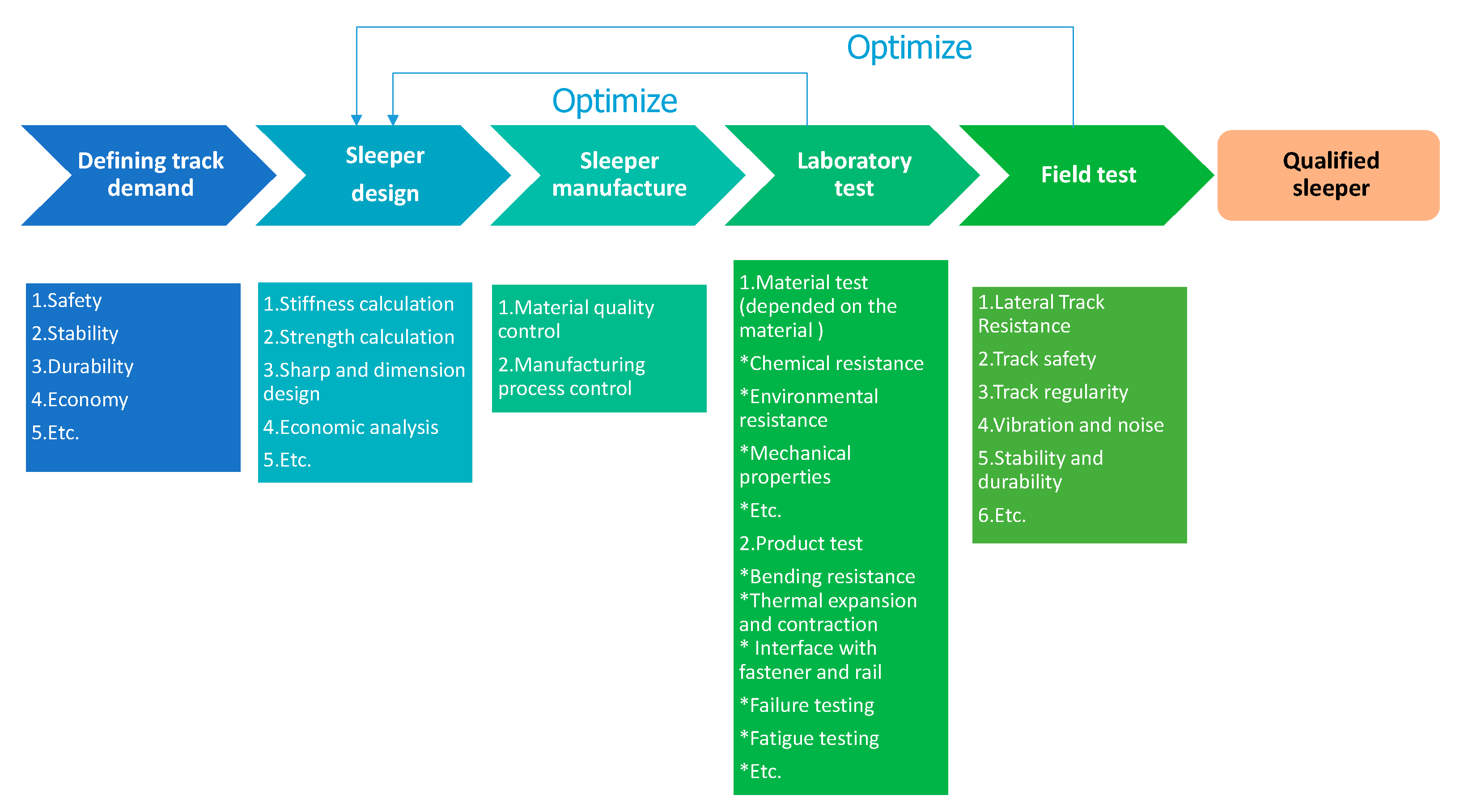
The above phenomena show that different types of plastic and composite sleepers have different forms of damage. Therefore, in addition to meeting the general test requirements for a particular railway track classification, each type of composite sleeper must still have special tests associated with the material characteristics and structural component behaviors suitable to specific requirements of each rail authorities. These also mean that it is highly necessary to optimize their own material characteristics of specific composite sleepers or bearers. It is also very critical that the sleepers or bearers provide assured capability to resist repetitive loading and provide sufficient durability [41]. The development framework of the plastic and composite sleepers could follow the process shown in Figure 6 [46]. Finally, the design principle of composite sleepers and bearers must be established to assure public safety over the whole life of the asset. Recent work has indicated that railway tracks could be designed up to 50 years with regular routine maintenance. However, bearers could have pre-mature failure due to irregularities [47,48,49]. The replacement or modification of the turnout bearers require appropriate structural design principle in assuring that safety margin and structural reliability can be retained without undermining long term sustainability [50,51,52,53].

8. Conclusions

So far, the rail industry has not had sufficient practical experience of using composites in rail infrastructures. Then, the industry often hesitates to adopt new materials due to the lack of track record and usage history. Since there are so many types of plastic and composite materials (with different structural behaviors and failure modes), this paper is aimed at presenting the criteria, fundamental and multi-disciplinary issues of bearer design in a grillage turnout system, in order to aid track engineers to make their decision in adopting new materials. Some of new materials’ characteristics are illustrated to provide an in-depth understanding into the static and dynamic performances of a turnout over its life cycle, as well as the benefits of new materials in reducing the depth of bearers while maintaining track stability. As a case study, a full-scale trial to investigate in-situ behaviours of a turnout grillage system using an alternative material, ‘fibre-reinforced foamed urethane (FFU)’ bearers, is presented. Based on the condition inspection and vibration measurements, it can be considered that FFU material has equivalent static and dynamic performance relatively to ‘timber bearers’ whilst it lasts much longer. Also, FFU bearers perform well in the high-frequency region but not very well in the low-frequency band. The insight presented in this paper will help the rail industry make a better decision for the suitable adoption of composites in railway infrastructure. It is clear that, to an extent, composites have a place in the industry application, but carefully bespoken design and application must also satisfy systems requirements (i.e., track stability, track stiffness, durability, impact resistance, environmental changes, etc.). Standard testing procedures (or type testing for manufacturing quality) cannot replace a design method. The reliable design method must also be established to ensure that future track maintenance does not suffer from the lack of accurate information about the true service life of the structural and safety-critical component in adverse rail environments.

Acknowledgments

The first author wishes to thank the Australian Academy of Science and the Japan Society for the Promotion of Sciences for his Invitation Research Fellowship (Long-term), Grant No. JSPS-L15701 at the Railway Technical Research Institute and The University of Tokyo, Japan. The authors are also sincerely grateful to the European Commission for the financial sponsorship of the H2020-RISE Project No. 691135 “RISEN: Rail Infrastructure Systems Engineering Network”, which enables a global research network that tackles the grand challenge of railway infrastructure resilience and advanced sensing in extreme environments (www.risen2rail.eu) [54]. The rigorous yet constructive and positive review comments are gratefully acknowledged. Also, we deeply appreciate valuable technical discussions during the ISO Standard Committee TC269 WG4 Plastic and Composite Sleepers; and hopefully this state-of-the-art review will form the basis for full standard development, taking into account both design and testing.

Author Contributions

S.K. conceived and designed the analyses and critical review criteria; S.K. and R.Y. analyzed the data; M.I. contributed materials/analysis advice and tools; S.K., R.Y., and M.I. wrote the paper.

Conflicts of Interest

The authors declare no conflict of interest.

References

  1. Kaewunruen, S. Acoustic and dynamic characteristics of a complex urban turnout using fibre-reinforced foamed urethane (FFU) bearers. In Proceedings of the 2013 International Workshop on Railway Noise, Uddevalla, Sweden, 9–13 September 2013. [Google Scholar]
  2. Kaewunruen, S. Monitoring in-service performance of fibre-reinforced foamed urethane material as timber-replacement sleepers/bearers in railway urban turnout systems. Struct. Monit. Maint. 2014, 1, 131–157. [Google Scholar]
  3. Kaewunruen, S. In situ performance of a complex urban turnout grillage system using fibre-reinforced foamed urethane (FFU) bearers. In Proceedings of the 10th World Congress on Rail Research, Sydney, Australia, 25–28 November 2013. [Google Scholar]
  4. Kaewunruen, S. Monitoring structural deterioration of railway turnout systems via dynamic wheel/rail interaction. Case Stud. Nondestr. Test. Eval. 2014, 1, 19–24. [Google Scholar] [CrossRef]
  5. Indraratna, B.; Salim, W.; Rujikiatkamjorn, C. Advanced Rail Geotechnology—Ballasted Track; CRC Press/Balkema: Leiden, The Netherlands, 2011. [Google Scholar]
  6. Remennikov, A.M.; Kaewunruen, S. A review of loading conditions for railway track structures due to train and track vertical interaction. Struct. Control Health Monit. 2007, 15, 207–234. [Google Scholar] [CrossRef]
  7. Standards Australia. Australian Standards: AS3818.2 Timber; Standards Australia: Sydney, Australia, 2001. [Google Scholar]
  8. RailCorp. Timber Sleepers & Bearers; Engineering Specification SPC 231; RailCorp: Sydney, Australia, 2012. [Google Scholar]
  9. Kaewunruen, S.; Remennikov, A.M. Dynamic flexural influence on a railway concrete sleeper in track system due to a single wheel impact. Eng. Fail. Anal. 2009, 16, 705–712. [Google Scholar] [CrossRef]
  10. Sekisui Co. Engineering Properties of FFU Materials; Sekisui Co.: Tokyo, Japan, 2012. [Google Scholar]
  11. Kaewunruen, S. Review of Alternative Fibre-Reinforced Foamed Urethane (FFU) Material for Timber-Replacement Turnout Bearers; Technical Report TR162; RailCorp: Sydney Australia, 2011. [Google Scholar]
  12. Kaewunruen, S. In-Situ Performance of Alternative Fibre-Reinforced Foamed Urethane (FFU) Material for Timber-Replacement Turnout Bearers; Technical Report TR188; RailCorp: Sydney Australia, 2011. [Google Scholar]
  13. Kaewunruen, S. Vertical and Lateral Stability Performance of Alternative Fibre-Reinforced Foamed Urethane (FFU) Material for Timber-Replacement Turnout Bearers; Technical Report TR197; RailCorp: Sydney Australia, 2012. [Google Scholar]
  14. Jenkins, H.H.; Stephenson, J.E.; Clayton, G.A.; Morland, J.W.; Lyon, D. The effect of track and vehicle parameters on wheel/rail vertical dynamic forces. Railw. Eng. J. 1974, 3, 2–16. [Google Scholar]
  15. CarbonLoc Pty Ltd. Comparison of Engineering Properties of Composite Materials for Sleepers; CarbonLoc Pty Ltd.: Toowoomba, Australia, 2014. [Google Scholar]
  16. Kreso, S.; Mirza, O.; He, Y.; Makin, P.; Kaewunruen, S. Field investigation and parametric study of greenhouse gas emissions from railway plain-line renewals. Transp. Res. D Transp. Environ. 2016, 42, 77–90. [Google Scholar] [CrossRef]
  17. Kaewunruen, S.; Remennikov, A.M. Current state of practice in railway track vibration isolation: An Australian overview. Aust. J. Civ. Eng. 2016, 14, 63–71. [Google Scholar] [CrossRef]
  18. Dindar, S.; Kaewunruen, S.; An, M. Identification of Appropriate Risk Analysis Techniques for Railway Turnout Systems. J. Risk Res. 2016. [Google Scholar] [CrossRef]
  19. Pen, L.L. Track Behaviour: The Importance of the Sleeper to the Ballast Interface. Ph.D. Thesis, University of Southampton, Southampton, UK, 2008. [Google Scholar]
  20. Esveld, C. Modern Railway Track; MRT-Productions: Zaltbommel, The Netherlands, 2001. [Google Scholar]
  21. Chandra, S.; Agarwal, M. Railway Engineering; Oxford University Press: Oxford, UK, 2007. [Google Scholar]
  22. Xiao, S.; Lin, H.; Shi, S.; Cai, L. Optimum processing parameters for wood-bamboo hybrid composite sleepers. J. Reinf. Plast. Compos. 2014, 33, 2010–2018. [Google Scholar] [CrossRef]
  23. Sadeghi, J.; Barati, P. Comparisons of the mechanical properties of timber, steel and concrete sleepers. Struct. Infrastruct. Eng. 2010, 8, 1–9. [Google Scholar] [CrossRef]
  24. Kaewunruen, S.; Lewandrowski, T.; Chamniprasart, K. Dynamic responses of interspersed railway tracks to moving train loads. Int. J. Struct. Stab. Dyn. 2017. [Google Scholar] [CrossRef]
  25. Manalo, A. Behaviour of Fibre Composite Sandwich Structures: A Case Study on Railway Sleeper Application. Ph.D. Thesis, Centre of Excellence in Engineered Fibre Composites Faculty of Engineering and Surveying University of Southern Queensland Toowoomba, Queensland, Australia, 2011. [Google Scholar]
  26. Li, D.; Selig, E. Evaluation of railway subgrade problems. Transp. Res. Rec. 1995, 1489, 17. [Google Scholar]
  27. Tata Steel. Steel Sleepers, 1st ed.; Tata Steel Europe Ltd.: Brockhurst Cres, Walsall, UK, 2014; Available online: http://www.tatasteeleurope.com/file_source/StaticFiles/Business_Units/Rail/Steel%20sleepers.pdf (accessed on 9 August 2016).
  28. Health and Safety Executive. Rail Track and Associated Equipment for Use Underground in Mines. 2007. Available online: http://www.hse.gov.uk/pubns/mines06.pdf (accessed on 5 August 2016).
  29. European Federation of Railway Trackworks Contractors. Newsletters EFRTC. 2007. Available online: http://www.efrtc.org/htdocs/newsite/newsletters.htm (accessed on 24 July 2016).
  30. Van Erp, G.; McKay, M. Recent Australian Developments in Fibre Composite Railway Sleepers. Electron. J. Struct. Eng. 2013, 13, 62–66. [Google Scholar]
  31. Bastos, P. Análise Experimental de Dormentes de Concreto Protendido Reforçados com Fibras de aço; Doutor em Engenharia de Estruturas, Universidade de São Paulo: São Paulo, Brazil, 1999. [Google Scholar]
  32. Griffin, D.W.P.; Mirza, O.; Kwok, K.; Kaewunruen, S. Finite element modelling of modular precast composites for railway track support structure: A battle to save Sydney Harbour Bridge. Aust. J. Struct. Eng. 2015, 16, 150–168. [Google Scholar] [CrossRef]
  33. Lampo, R. Recycled Plastic Composite Railroad Crossties; Construction Innovation Forum US Army ERDC-CERL: Champaign, IL, USA, 2002. [Google Scholar]
  34. Griffin, D.; Mirza, O.; Kwok, K.; Kaewunruen, S. Composite slabs for railway construction and maintenance: A mechanistic review. IES J. A Civ. Struct. Eng. 2014, 7, 243–262. [Google Scholar]
  35. Bilec, M.; Ries, R.; Matthews, H.; Sharrard, A. Example of a Hybrid Life-Cycle Assessment of Construction Processes. J. Infrastruct. Syst. 2006, 12, 207–215. [Google Scholar] [CrossRef]
  36. Crawford, R. Greenhouse Gas Emissions Embodied in Reinforced Concrete and Timber Railway Sleepers. Environ. Sci. Technol. 2009, 43, 3885–3890. [Google Scholar] [CrossRef] [PubMed]
  37. Intergovernmental Panel on Climate Change (IPCC). Climate Change 2014: Synthesis Report. Contribution of Working Groups I, II and III to the Fifth Assessment Report of the Intergovernmental Panel of the Intergovernmental Panel on Climate Change; IPCC: Geneva, Switzerland, 2014. [Google Scholar]
  38. Kaewunruen, S.; Paes Cortes Lopes, L.M.; Papaelias, M.P. Influences of sleeper/crosstie material choices on Georisks in railway systems under climate uncertainties. In Proceedings of the CESARE17 Coordinating Engineering For Sustainability and Resilience, Jordan University of Science and Technology, Dead Sea, Amman, Jordan, 3–8 May 2017. [Google Scholar]
  39. Zhao, J.; Chan, A.H.C.; Burrow, M.P.N. Reliability analysis and maintenance decision for railway sleepers using track condition information. J. Oper. Res. Soc. 2007, 58, 1047–1055. [Google Scholar] [CrossRef]
  40. Kaewunruen, S. Experimental and Numerical Studies for Evaluating Dynamic Behaviour of Prestressed Concrete Sleepers Subject to Severe Impact Loading. Ph.D. Thesis, University of Wollongong, Wollongong, Australia, 2007. [Google Scholar]
  41. European Committee for Standardization (CEN). Railway Applications. Track. Concrete Sleepers and Bearers. Part 1: General Requirements; European Standard EN 13230–1; CEN: Brussels, Belgium, 2016. [Google Scholar]
  42. European Committee for Standardization (CEN). Railway Applications. Track. Concrete Sleepers and Bearers. Part 2: Prestressed Monoblock Sleepers; European Standard EN 13230–2; CEN: Brussels, Belgium, 2016. [Google Scholar]
  43. European Committee for Standardization (CEN). Railway Applications. Track. Concrete Sleepers and Bearers with under Sleeper Pads; European Standard EN 16730; CEN: Brussels, Belgium, 2016. [Google Scholar]
  44. Ferdous, W.; Manalo, A.; Aravinthan, T.; Van Erp, G. Composite railway sleepers: New developments and opportunities. In Proceedings of the 11th International Heavy Haul Association Conference: Operational Excellence (IHHA 2015), Perth, Australia, 21–24 June 2015. [Google Scholar]
  45. Ferdous, W.; Manalo, A.; Van Erp, G.; Aravinthan, T.; Kaewunruen, S.; Remennikov, A.M. Composite railway sleepers—Recent developments, challenges and future prospects. Compos. Struct. 2015, 134, 158–168. [Google Scholar] [CrossRef]
  46. You, R.; Silva, E.A.; Kaewunruen, S. Methodologies for designing railway plastic and composite sleepers. Chin. J. Railw. Eng. 2017, in press. [Google Scholar]
  47. Vu, M.; Kaewunruen, S.; Attard, M. Nonlinear 3D finite element modeling for structural failure analysis of concrete sleepers/bearers at an urban turnout diamond. In Handbook of Materials Failure Analysis with Case Studies from the Chemicals, Concrete and Power Industries; Butterworth-Heinemann: Oxford, UK, 2016; Chapter 6; pp. 123–160. ISBN 97-0-08-100116-5. [Google Scholar]
  48. Gamage, E.K.; Kaewunruen, S.; Remennikov, A.M.; Ishida, T. Toughness of Railroad Concrete Crossties with Holes and Web Openings. Infrastructures 2017, 2, 3. [Google Scholar] [CrossRef]
  49. Gamage, E.K.; Kaewunruen, S.; Remennikov, A.M.; Ishida, T. Reply to Giannakos, K. Comment on: Toughness of Railroad Concrete Crossties with Holes and Web Openings. Infrastructures 2017, 2, 5. [Google Scholar] [CrossRef]
  50. Silva, E.A.; Pokropski, D.; You, R.; Kaewunruen, S. Comparison of structural design methods for railway composites and plastic sleepers and bearers. Aust. J. Struct. Eng. 2017. accepted. [Google Scholar]
  51. Nagafuji, T.; Abe, N. Fifteen Years’ Experience with Synthetic Sleeper. RTRI Rep. 1997, 11, 43–48. (In Japanese) [Google Scholar]
  52. Oikawa, Y. Evaluation of FFU Sleeper installed in Track for 30 years. J. Jpn. Railw. Civ. Eng. Assoc. 2012, 50–58, 41–44. (In Japanese) [Google Scholar]
  53. You, R.; Li, D.; Ngamkhanong, C.; Janeliukstis, J.; Kaewunruen, S. Fatigue life assessment methods for railway prestressed concrete sleepers. Front. Built Environ. 2017. accepted. [Google Scholar]
  54. Kaewunruen, S.; Sussman, J.M.; Matsumoto, A. Grand Challenges in Transportation and Transit Systems. Front. Built Environ. 2016, 2, 4. [Google Scholar] [CrossRef]
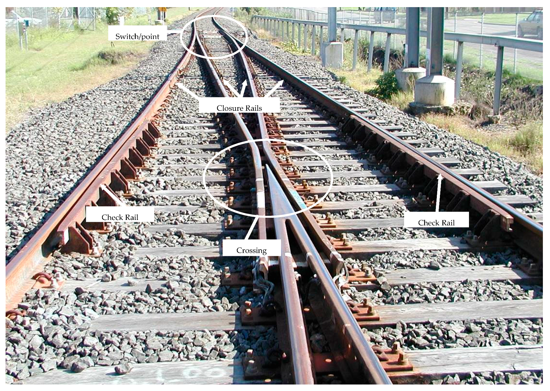
Figure 1. Typical turnout geometry.
Infrastructures 02 00013 g001
Figure 2. Transfer zone at crossing where a conical wheel traversing a v-crossing (removal of white paint showing the wheel contact band) and running over a dip angle inducing impact force. Note that axle box acceleration responds only to the wheel trajectory path, which is the gross resultant of combined degradations of crossings, pads, bearers, ballast, and support formation.
Infrastructures 02 00013 g002
Figure 3. Y-Steel-Sleeper.
Infrastructures 02 00013 g003
Figure 4. General condition of the double slips.
Infrastructures 02 00013 g004
Figure 5. Spectral analysis of track displacements over the double slips. The track geometry data were derived from the axle box accelerations over track length (on time domain series). Its spectral responses imply the movements of track associated with train motions or excitation wavelength (equivalent to surface irregularities). Note that the performance of FFU trials has been monitored after three months of revenue services (to assure appropriate settlement and densification of ballast after construction). More details are in [1,2,3].
Infrastructures 02 00013 g005
Figure 6. Composite sleepers develop process.
Infrastructures 02 00013 g006
Table 1. Timber species for railway turnout applications [3].
GroupCommon NameScientific Name
Group 1Ironbark GreyE. Siderophloia
Ironbark GreyE Paniculata
Ironbark GreyE Drepanophylla
Ironbark Red (broad leaved)E Fibrosa
Ironbark Red (narrow leaved)E Creba
Ironbark RedE Sideroxylon
Gum Slaty or Box SlatyE Dawsonil
Box WhiteE Albens
Group 2Box GreyE Microcarpa
Box GreyE Moluccana
Tallow woodE Microcorys
Gum GreyE Punctata
Gum GreyE Propinqua
Gum Forest RedE Tereticornis
Mahogany WhiteE Acmeniodies
Table 2. Timber design for railway turnout applications [3].
Cross Section (mm)ApplicationStandard Timber Lengths Supporting Turnouts and Crossovers (m)
250 × 180 *General2.8, 3.0, 3.2, 3.4, 3.6, 3.8, 4.0, 4.2, 4.4, 4.6, 4.8, 5.0, 5.2, 5.4, 5.8, 6.0, 6.2, 6.4
250 × 200 *Points (motor)2.8, 3.0, 3.2, 3.4, 3.6, 3.8, 4.0, 4.2, 4.8, 5.0, 5.2
* Tolerance: length +50–0 mm; width +10–0 mm; thickness +10–0 mm.
Table 3. Basic properties of FFU material in comparison with timber bearers.
Properties [24]Australian Hardwood Bearers 1Birch (Softwood) Bearers 2FFU Bearers [3]
NewAfter 10 YearsAfter 15 YearsAfter 30 Years
Service life (years)5–105–1050403520
Density (kg/m3)1050–1120750740740740740
Bending strength (MPa) > 706580142125131116
Vertical compression strength (MPa) > 40604058666355
Shear strength (MPa) > 76.112109.59.67
Elastic modulus (MPa) > 600016,00071008100804487888414
Fatigue flexural strength 50,000 cycles at 40 MPa50,000 cycles at 40 MPa1 million cycles at 94 MPa
Hardness (MPa)1017282517
Water absorption (mg/cm2) < 101371373.33.33.33.3
Impact bending strength (MPa)
@ 20 °C-2041---
@ −20 °C-841---
Destructive voltage (kV)
- dry (>20,000)88>25>25>25>25
- wet (>20,000)<1<122242325
Insulation resistance (Ω)
- dry (>1.0 × 10⁴)6.6 × 1076.6 × 1071.6 × 10132.1 × 10123.6 × 10128.2 × 1011
- wet (>1.0 × 10⁴)5.9 × 1045.9 × 1041.4 × 1085.9 × 10101.9 × 109-
Dog spike pull-out strength (kN) > 15252528282322
Screw spike pull-out strength (kN) > 30404365394433
1 Timber bearer properties are derived from AS1720 Strength Group 2 [3]. 2 Birch timber bearer properties are derived from the technical datasheet [3]. This timber is equivalent to soft wood.
Table 4. Comparative properties of composite materials [3].
PropertiesAxionCarbonloc
Flexural Strength20.6 MPa70 MPa
Modulus of Elasticity1724 MPa5000 MPa
Shear Strength7.5 MPa15 MPa
Compression perpendicular to grain8.2 MPa50 MPa
Average Flame Spread Index147.430
Smoke Density Dmax16.91
Table 5. Expected Life Cycle of Different Types of Sleepers.
MaterialService Life (Years)MaterialService Life (Years)
Timber15–25 [17]Steel20–30 [17]
Concrete50 [17]Plastic/Polymerover 50 [14]
Table 6. Georisks of rail infrastructure due to sleeper materials.
Climate Impact GroupRisksSafety ImpactPerformance ImpactLikely Negative Impact from Climate ChangeLong or Short TermInfluence of Sleepers
Sea Level RiseIncreased flooding generallyHighHighHighLong●  Regarding the design of the track bed, the load distribution pattern at the sleeper/ballast interface is a parameter of critical importance since it is a major function of the sleeper smoothly distributes the loads imposed on it by rails to the subsequent layers.
●  The formation is often damaged by excessive moisture content especially when flooding occurs after rains. Concrete sleepers tend to cause formation failure quicker than other sleepers because they are often used in a heavier operation, resulting in a higher bearing pressure. Therefore, if formation is undermined by water, it is highly likely that such track will fail even though it looks perfect from the top view.
●  Reconstruction of track formation and foundation is required if damage occurs.
●  Ballast-sleeper interaction will be negatively affected by incompressible fluid stagnant on tracks. For timber sleepers softened by moisture content, the ballast can further damage the soffit of the sleepers and the ballast-sleeper interlocking can be impaired.
●  For steel sleepers, supporting ballast can be easily washed away from the climate effect (due to relatively less lateral friction between ballast and steel sleepers).
Increased RainfallSettlementMedium HighLowLongNeed to monitor the ground movement and the relationship with rainfall intensity. Settlement under heavy haul track is usually accelerating higher. However, deteriorated timber sleepers by moisture content can lose the vertical stiffness and yield excessive deformation and higher total settlement. Ballast voids and pockets could be expected under timber and steel sleepers. Due to their relatively lightweight, the dancing and hanging sleepers can further impose detrimental impact loading conditions on ballast and formation.
Increased RainfallStabilityHighHighHighLongEmbankment, rock cutting, earth cuttings and culverts are at risk of being instable, disregarding of any type of sleepers.
HeatTrack bucklingHighHighHighLong●  Sleepers have the major role of providing satisfactory lateral resistance to avoid lateral movements of rails. If the lateral forces overcome the lateral resistance of sleepers, rail buckling may occur. In fact, timber and steel sleepers perform poorly laterally under elevated temperature.
●  The elevated temperature can increase ballast dilation and curve pull-out on curved track. Tracks with steel and timber sleepers are prone to buckling and large lateral movement. With large sideway movement, the timber and steel sleepers tend to hang on the rail without support from ballast. The hanging sleepers will aggravate sleeper-ballast interaction and impose aggressive impact loading on railway tracks, failing track components and formation.
Increased RainfallGeotechnical FailureMediumHighHighLong●  Cyclic stresses are a major concern for the stability of the subgrade. Repeated traffic overloads are related with many subgrade problems, being the progressive shear failure and excessive plastic deformation some of the causes of formation failure most commonly found in railways around the world. The differential local track stiffness would aggravate the impact loading at sleeper-ballast interface and further damage the tracks. Furthermore, the overstress can wear the superficial soil of the subgrade that combined with water form mud. More than the weakening of the soil, this mud under repeated loads can pumps into the ballast and damage the drainage of the track (using any type of sleepers). Fine-grained soils, as clays, are usually more susceptible to these failures modes.
●  Timber sleepers are often decayed with high moisture content.
●  Steel sleepers can be oxidized at higher level. Steel sleepers can aggravate the ballast conditions and incur ballast dilations induced by fluid flow.
Cold SnapDamageMediumHighMediumShort●  Steel, plastic and resin in composite sleepers become very brittle in very low temperature. These sleepers could be damaged by ice-stiffened tracks, resulting in excessive groundborne noise and vibration.
●  Freeze-thaw effects can cause concrete sleeper damage.
●  Ice-stiffening can cause ballast dilation, cracking subballast, cracking formation, and frozen rail joints.
●  Icing can also cause frozen rubber/under sleeper pad/under ballast mat.
●  Due to their lightweights, timber and steel sleepers could not sufficiently restore lateral track stiffness in cold temperature and could result in the curve pull-in. Then, the hanging timber and steel sleepers can increase dynamic effects on sleeper-ballast-formation interaction, and could lead to excessive ballast dilation, poor track geometry and unbalanced track loading (causing low rail to damage formation further).
Table 7. Track category in Europe.
Track CategoryCommon UsageTypical Axle LoadTypical Maximum SpeedTypical Rail Section
TC1Urban light rail and some Industrial trackBetween 100 kN and 130 kN100 km/h49E1
TC2Urban light rail and some Industrial track160 kN140 km/h54E1
TC3Conventional main line railways225 kN200 km/h60E1
High speed railways200 kN320 km/h60E1
TC4Mixed traffic line300 kN200 km/h60E1