Article

Evaluation of an Approximate Seismic Assessment Procedure for Load-Bearing Masonry Buildings

by
Stylianos I. Pardalopoulos
1,*,
Anastasia E. Gkektsi
2 and
Vassilios A. Lekidis
2
1
Department of Civil Engineering, Democritus University of Thrace, 671 50 Xanthi, Greece
2
ITSAK Research Unit of the Earthquake Planning and Protection Organization, 551 02 Thessaloniki, Greece
*
Author to whom correspondence should be addressed.
Infrastructures 2025, 10(5), 118; https://doi.org/10.3390/infrastructures10050118
Submission received: 5 March 2025 / Revised: 26 April 2025 / Accepted: 6 May 2025 / Published: 12 May 2025

Abstract

The Building Inspection Priority Index (BIPI) method for masonry structures is an approximate procedure for the preliminary assessment of the seismic capacity of existing load-bearing masonry buildings and for the prioritization of each building for conducting third-tier seismic assessments. This study investigates the applicability and reliability of the BIPI method by evaluating the seismic adequacy of four existing masonry buildings, located in Epirus and Central Macedonia, Greece, and by comparing the results with the damage sustained by these buildings during previous strong earthquakes.

1. Introduction

Masonry construction dominated building practices until the early-20th century. Since then, although reinforced concrete has largely replaced it, masonry remains in use globally due to its ecological benefits, cost-effectiveness, and aesthetic appeal. Consequently, existing masonry buildings exhibit a diverse array of typological and structural features, ranging from unreinforced structures with mixed structural systems and inadequate diaphragm action at floor levels to contemporary constructions employing current building techniques (Figure 1).
The high vulnerability observed in load-bearing masonry buildings following moderate or strong seismic events underscores a scientifically and economically challenging task: assessing the seismic adequacy of such buildings to identify seismic-risk cases and implementing necessary strengthening interventions to prolong their service life. To address this challenge, extensive research has been conducted over recent decades aimed at predicting potential damage to existing masonry buildings during significant seismic events. These studies have led to the development of numerous assessment methodologies, which, despite their distinct features, can be categorized into three primary types based on the level of knowledge and the computational effort required for conducting assessments, and consequently determining the accuracy of the results obtained. These categories are commonly referred to as first-tier, second-tier, and third-tier assessment methodologies.
First-tier seismic assessment procedures for masonry buildings ([1,2,3,4,5,6,7,8,9,10,11,12,13,14,15], etc.) are designed to identify, catalog, and screen a substantial number of buildings that may pose seismic hazards. The outcomes of these procedures do not always carry absolute objective significance since the evaluation of the inspected buildings is based on statistical analyses of the seismic responses of similar typological and structural buildings during previous major earthquakes; however, they do provide a basis for the comparative ranking of buildings. These procedures aim to minimize ambiguity and reduce reliance on subjective judgment, making them accessible to a broad range of potential assessors, including civil and structural engineers, architects, design professionals, building officials, construction contractors, firefighters, architecture or engineering students, and other individuals with general knowledge or experience in building design or construction. Based on the collected data, buildings are assigned a global vulnerability score, categorizing them as either safe or potentially hazardous, the latter warranting a more detailed seismic assessment. Furthermore, the results from these first-tier seismic assessment procedures can be utilized for various purposes: assessing the seismic retrofitting needs of a community or agency; designing seismic hazard mitigation programs; developing building inventories for monitoring earthquake impacts or facilitating damage and loss assessments; planning post-earthquake building safety evaluations; and generating building-specific seismic vulnerability information for purposes such as insurance rating, decision making during property transfers, and potentially triggering remodeling requirements during the permitting process.
The second-tier assessment methods for masonry structures (e.g., [2,3,16,17,18,19]) involve a more detailed examination of the seismic response of the subject building. Like the first-tier assessment methods, these procedures are designed for the rapid evaluation of potentially hazardous buildings but typically require a more detailed inspection and a higher computational effort. The objective of second-tier assessment methods is to reclassify masonry structures that were deemed seismically vulnerable during the first-tier seismic assessment. This reclassification is based on the documentation and evaluation of technical characteristics as well as the consideration of social criteria. The second-tier assessment requires documentation of the geometry and pathology of the building, certain in situ material testing (e.g., [20]), and basic calculations for the quantitative evaluation of characteristic indices (e.g., [21,22]), without detailed simulation and analysis of the load-bearing structure. Moreover, these methods are primarily intended for specialized structural engineers with expertise in identifying the structural characteristics of the assessed buildings. Consequently, second-tier assessments offer a more comprehensive understanding of the seismic behavior of the structure by estimating its seismic capacity through damage indices, while still maintaining the capacity for rapid and widespread application to existing buildings.
The third-tier assessment procedures ([2,3,23,24,25,26,27,28,29,30,31,32,33,34,35,36,37,38,39,40,41], etc.) require detailed simulation of the examined masonry buildings using seismic analysis, which employs elastic and/or inelastic methodologies, and advanced numerical tools, such as shell and/or linear finite elements, macro-elements, and equivalent frame elements. These procedures generally necessitate a high level of expertise, access to expensive software, proper assessment of the mechanical properties of masonry ([42,43,44,45]), diagnostic equipment, and a commensurate budget. Therefore, third-tier assessments of existing buildings produce highly detailed results regarding seismic response and capacity. However, due to budgetary constraints, they can only be conducted for a limited number of buildings, usually for masonry buildings that do not meet the acceptance criteria of the first-tier and second-tier procedures or for buildings of high historical and cultural value.
To address the problem of rapidly identifying seismically vulnerable masonry structures, the Hellenic Earthquake Planning and Protection Organization (EPPO) issued a pre-standard for second-tier seismic assessment of existing load-bearing masonry (LBM) buildings [46]. This pre-standard utilizes the Building Inspection Priority Index (BIPI) method for masonry structures as an approximate process for assessing the seismic capacity of public LBM buildings. Through this method, the examined buildings are hierarchized into a unified database in a more precise and rational manner compared to classifications obtained by applying first-tier seismic assessment procedures. This allows for the prioritized selection of limited cases, depending on the financial capacity of the respective public body, for conducting third-tier seismic assessment (KADET [23], EN1998-3 [24]).
The present study investigates the applicability and reliability of the BIPI method for masonry buildings by applying it to four existing masonry buildings in Greece: the Ecclesiastical School within the complex of the Holy Monastery of the Nativity of Theotokos, located in Vellas, Epirus, and the Hellenic High School, the Hellenic Consulate, and the 12th Primary School, all located in Thessaloniki, Central Macedonia, Greece. The examined buildings, constructed with different types of masonry, were evaluated for their seismic capacity using the second-tier method. The assessment results are then compared with the structural damage sustained by the buildings during past strong earthquakes in the respective regions.

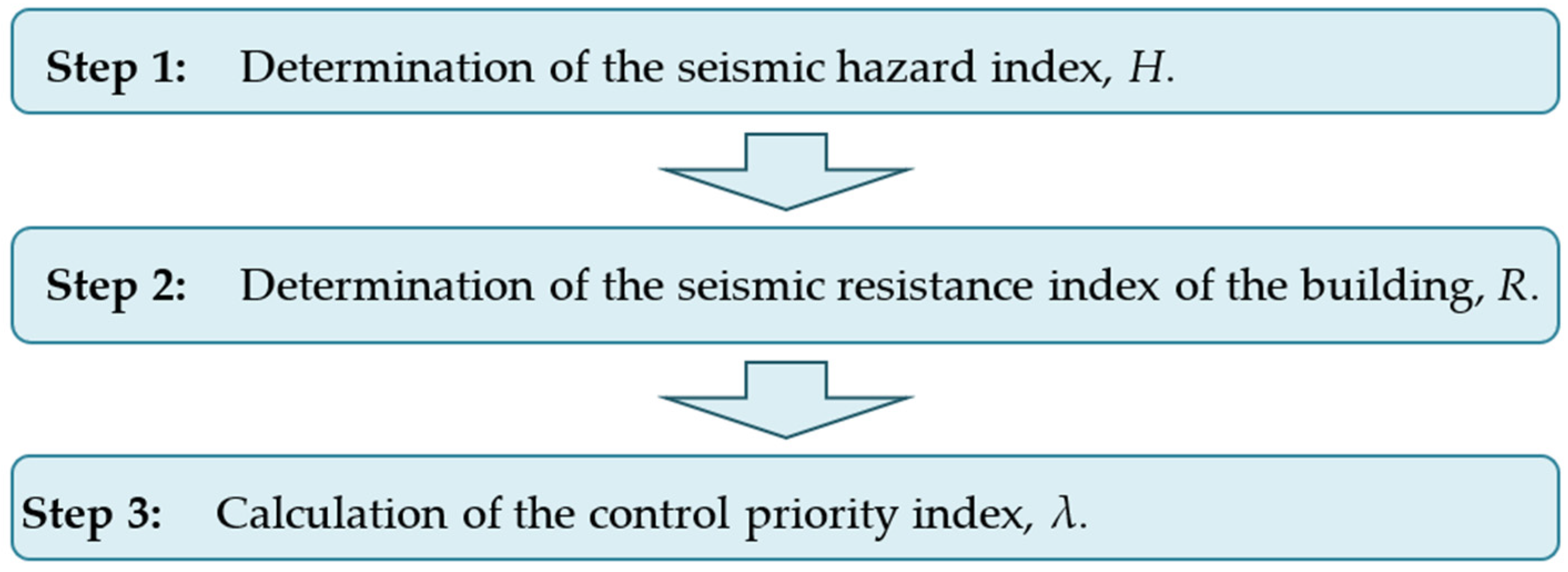
2. The Building Inspection Priority Index Method for Masonry Buildings

The Building Inspection Priority Index (BIPI) method for masonry structures [46] is a second-tier empirical procedure issued by the Hellenic Earthquake Planning and Protection Organization (EPPO). This method aims to reclassify common masonry buildings (residences, public buildings, etc.) that received a rating below a specified threshold in the first-tier seismic assessment procedure [8] in a more detailed manner. Through this method, seismically inadequate masonry buildings are reclassified based on the depiction and evaluation of their technical characteristics, derived from drafting geometry and pathology sketches, visual assessment, and in situ tests of structural materials.
The BIPI method is a three-step procedure that empirically leads to the rating of the examined masonry buildings in a priority list for conducting third-tier seismic assessment procedures (KADET [23], EN1998-3 [24]). Following the philosophy of an approximate methodology for the seismic assessment of historical masonry buildings [47], the method uses procedures from EN1998-1 [48], EN1998-3 [24], and EN1996-1-1 [49], which are modified based on data from experiments on masonry walls with concrete, wood, or metal ties, and data from the recorded response of instrumented load-bearing masonry structures during past earthquakes in Greece and across Europe.
The method does not require simulation and seismic analysis of the examined building. Instead, it is applied by performing basic calculations to quantitatively estimate characteristic indices, while also considering social criteria. The classification relies on comparing the seismic hazard at the building’s site (H) and the building’s seismic resistance (R) according to the fundamental safety inequality:
H < R
The application of the methodology to a group of buildings aims to calculate the Control Priority Index, λ, which determines the priority of each building for further assessment compared to others within the same group. The empirical nature of the method does not theoretically guarantee the precise value of the H/R ratio. Additionally, an H/R < 1 ratio does not necessarily prove the seismic adequacy of the building. The process of applying the BIPI method is illustrated schematically in Figure 2.

2.1. Determination of the Seismic Hazard Index

The seismic hazard index, H, reflects the seismic demand at the site of the examined building. It is assessed based on the expected seismic action and the probability of collision with neighboring structures, according to Equation (2):
H = 0.75·H1 + 0.25·H2
where H1 = a·s is the seismic action index determined in relation to the seismic hazard zone and the soil category of the building’s location, and H2 is the influence index of neighboring buildings. The values of coefficients a, s, and H2 are obtained from Table 1 and Table 2.

2.2. Determination of the Seismic Resistance Index of the Building

The seismic resistance index R is computed as the sum of ten partial indices, Ri (i = 1, 2, …, 10), each representing a parameter influencing the building’s lateral stiffness. These indices fall into two categories: the first relates to the strength of masonry walls as individual elements (material, thickness, opening ratio and placement, presence of horizontal ties, structural damage); the second concerns factors affecting the building’s overall structural behavior (e.g., connection between transverse walls, diaphragm action, plan shape, and height). A brief description of each index follows; full details are provided in [46].

2.2.1. Index for Shear Resistance at the Critical Floor Level (R1)

This index assesses the seismic resistance of the critical floor, typically the ground floor, unless a significant reduction in stiffness occurs at a higher level. It is calculated as
R1 = 12·(m·λm)·[∑Aw/(n·A)]; R1 ≤ 1.00
where m (0.25 to 1.00) depends on masonry properties; λm (0.70 to 1.00) accounts for the degree of connection between masonry units and/or the level of mortar disintegration; ∑Aw is the total wall cross-sectional area at the critical floor level in the most vulnerable plan direction (walls with length lw < 1.00 m are excluded); n is the number of stories above the critical floor level; and A is the plan area of the examined floor level.

2.2.2. Index for Openings in Load-Bearing Walls (R2)

Index R2 is calculated using
R2 = [1/(α + 0.4)] − 0.7; R2 ≤ 1.0
where α is the ratio of total opening lengths to the total wall length (including openings) in the critical direction at the ground floor.

2.2.3. Index for Horizontal Ties (R3)

This empirical index accounts for the lack of horizontal ties. Values range from 0.50 (no ties) to 1.00 (ties above openings and at all floor and roof levels), based on the configuration.

2.2.4. Index for Diaphragm Action (R4)

This index assesses diaphragm stability and the connection to load-bearing walls, depending on wall arrangement and diaphragm continuity. Possible values are listed in Table 3.

2.2.5. Index for Openings near Wall Corners (R5)

The index represents the vulnerability of narrow piers (<1.0 m) at external corners:
R5 = −[λ + (α/2·γ)·(α/∑lw)]; R5 ≥ −1.0
where λ is 0.25 or 0.50, depending on the presence of vulnerable piers in one or both directions; α is their count; γ is the number of external corners; and ∑lw is the total pier length.
If proper floor and roof ties exist, α is reduced by 50%.

2.2.6. Index for Damage to Load-Bearing Walls (R6)

The index assumes a value of 1.00 for undamaged walls, reduced to 0.75 for minor localized cracks (<1.0 mm) and to 0.5 for widespread or moderate cracks (<2.0 mm). Severe damage necessitates a third-tier assessment.

2.2.7. Index for Transverse Walls Connections (R7)

The index evaluates connections at wall intersections: R7 = 1.00 if fully interconnected (including internal walls); R7 = 0.80 if only perimeter walls are connected; R7 = 0.40 if none are connected.

2.2.8. Index for Out-of-Plane Loading of Perimeter Walls (R8)

R8 accounts for vulnerability to out-of-plane failure:
R8 = 6·√t/ with R8 ≤ 1.0
where t is wall thickness and is the wall length between transverse connections. The index is computed for each wall group, and the minimum R8 characterizes the building.

2.2.9. Index for Regularity in Floor Plan (R9)

For orthogonal plans, R9 is associated with the ratio of the lengths of the longer side (Lmax) to the shorter side (Lmin) of the critical floor in the two principal plan directions, λ = Lmax/Lmin.
-
λ < 4.0: regular (R9 = 1.00)
-
4.0 ≤ λ < 8.0: partially regular (R9 = 0.75)
-
λ ≥ 8.0: irregular (R9 = 0.50)
For plans with irregular shapes (L, T, H, E, etc.), R9 is based on the sum of the area of the recesses, ∑AE, and the area of the largest recess, AE,max, as fractions of the total plan area, Atot:
-
AE < 0.25Atot or AE,max < 0.15Atot: regular (R9 = 1.00)
-
0.25Atot ≤ ∑AE < 0.40Atot or 0.15AtotAE,max < 0.25Atot: partially regular (R9 = 0.75)
-
AE ≥ 0.40Atot or AE,max ≥ 0.25Atot: irregular (R9 = 0.50)
Even if only the critical story is regular, the building is considered regular.

2.2.10. Index for Regularity in Height (R10)

The index assesses lateral stiffness distribution:
-
If one floor’s area is ≥75% of the one above/below, or if upper recesses <40% of ground floor: regular
-
If one floor’s area ranges from 60% to 75% of the one above/below, or if recesses range from 40% to 60% of the ground floor area: partially regular
-
If one floor’s area is <60% of the one above/below, or if recesses >60% of the ground floor area: irregular
Alternatively, if wall area ∑Aw (excluding openings) differs by
-
<30% between floors: regular
-
30–50%: partially regular
-
>50%: irregular
On sloped ground, for height difference between lowest and highest ground levels:
-
<1 story: regular
-
1–2 stories: partially regular
-
>2 stories: irregular
The R10 index is assigned 1.00 for regular buildings, 0.75 for partially regular buildings, and 0.50 for irregular buildings.
The overall seismic resistance index, R, is the weighted sum of the 10 partial indices Ri, each multiplied by its corresponding weighting coefficient, ri. Table 4 summarizes the indices and coefficients.
According to the BIPI method for masonry structures, the seismic resistance index of the examined building is obtained by summing the individual resistance indices, each multiplied by its corresponding weighting coefficient, as follows:
R = 0.20·R1 + 0.15·(R3 + R5) + 0.10·(R4 + R7 + R8) + 0.05·(R2 + R6 + R9 + R10)

2.3. Calculation of the Control Priority Index

The control priority index, λ, for the examined building derives as the quotient of the seismic hazard index at the site of the examined building, H, divided by the building’s seismic resistance index, R, as follows:
λ = 100·(H/R)
The control priority index, λ, establishes each building’s priority for subsequent assessment relative to others in the same group. It is important to note that the empirical nature of the method means that the precise value of the H/R ratio may not be theoretically guaranteed. Furthermore, an H/R ratio < 1 does not inherently demonstrate the seismic adequacy of the examined building.
The significance of the BIPI method for masonry buildings lies in its applicability to a wide range of load-bearing masonry buildings sharing common characteristics in terms of (1) the user population and potential frequency of gatherings, (2) economic value, (3) administrative or social importance, and (4) historical significance. The primary objective of this method is to prioritize the examined buildings, enabling their subsequent detailed seismic evaluation using advanced third-tier procedures, such as KADET [23], EN1998-3 [24], etc.

3. Application of the BIPI Method to Four Existing Masonry Buildings

The present study investigates the applicability and reliability of the second-tier Building Inspection Priority Index (BIPI) method for masonry buildings through its implementation in four case studies. The first case involves the Ecclesiastical School of the Holy Monastery of the Nativity of Theotokos, in Vellas, Ioannina Prefecture, Greece, which sustained significant damage during an earthquake in the Epirus region on 15 October 2016 (M5.3), with the epicenter in close proximity to the monastery. The other three cases concern neoclassical buildings in Thessaloniki, Central Macedonia, Greece, which suffered varying degrees of damage during the Volvi earthquake on 20 June 1978 (M 6.5).
The aim of this investigation is twofold: first, it assesses the ease of application of the BIPI method to four load-bearing masonry buildings representative of many public buildings constructed in the 20th century; second, it correlates the derived index values with the structural damage observed in these buildings after the earthquakes.

3.1. Description of the Examined Buildings

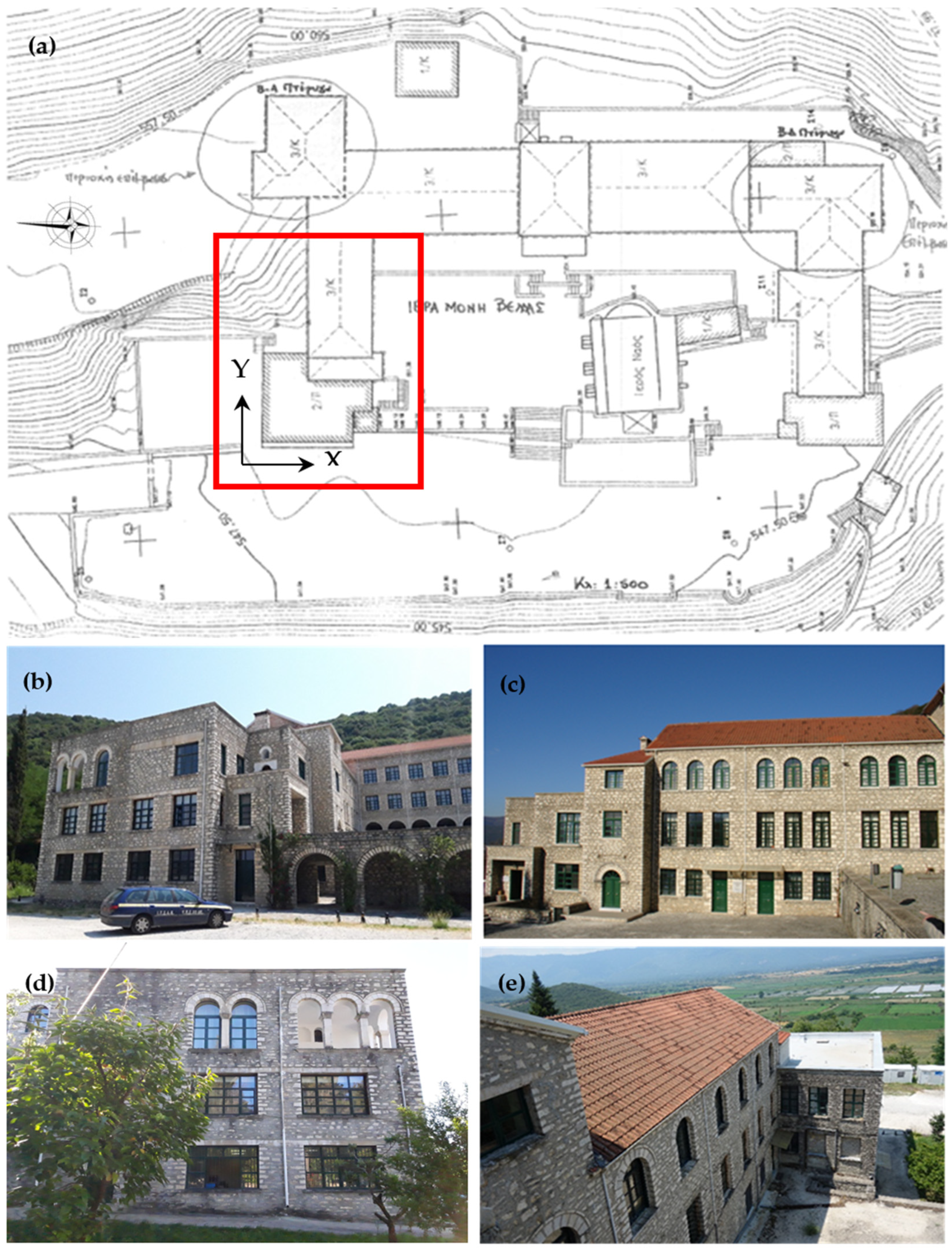
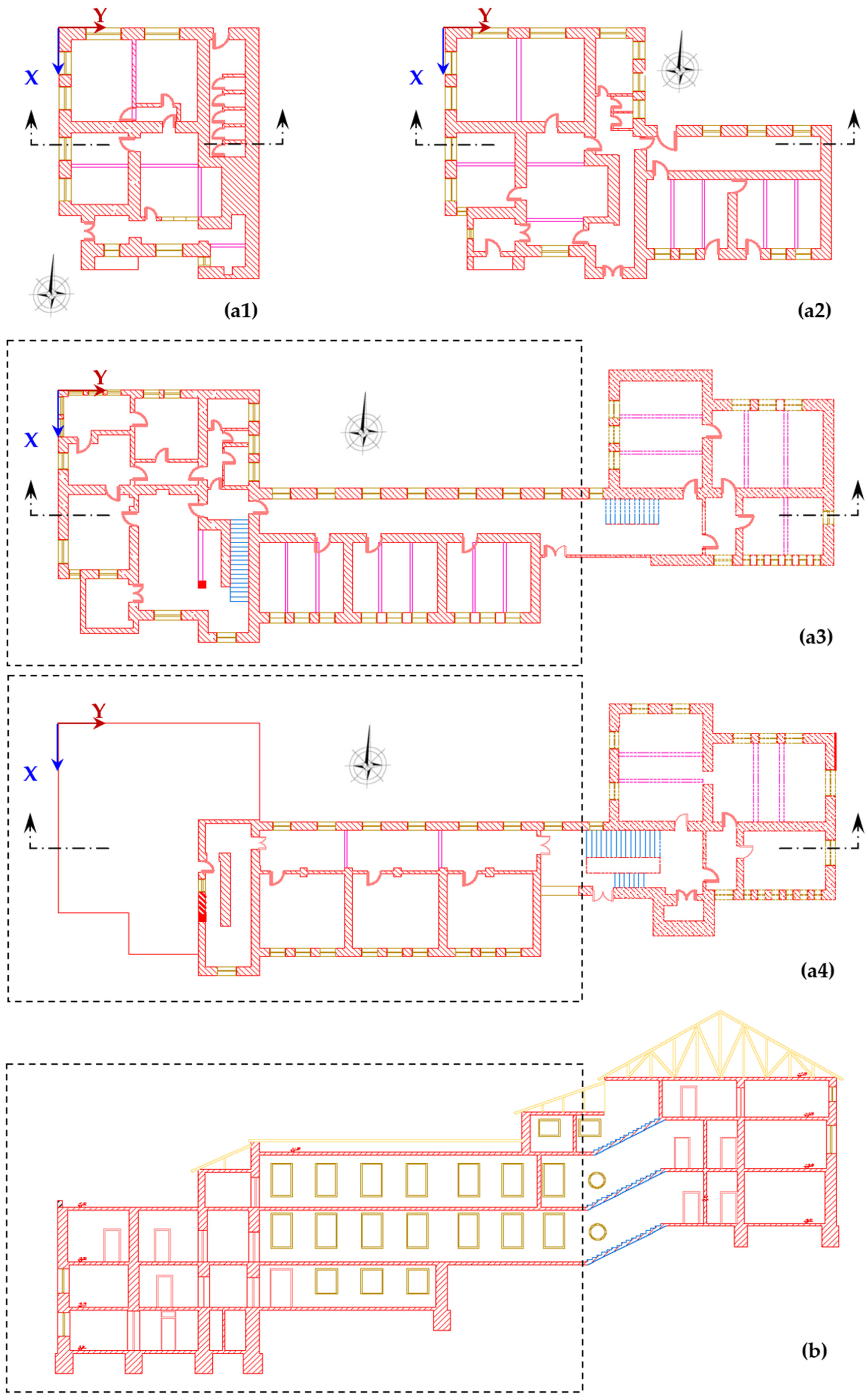
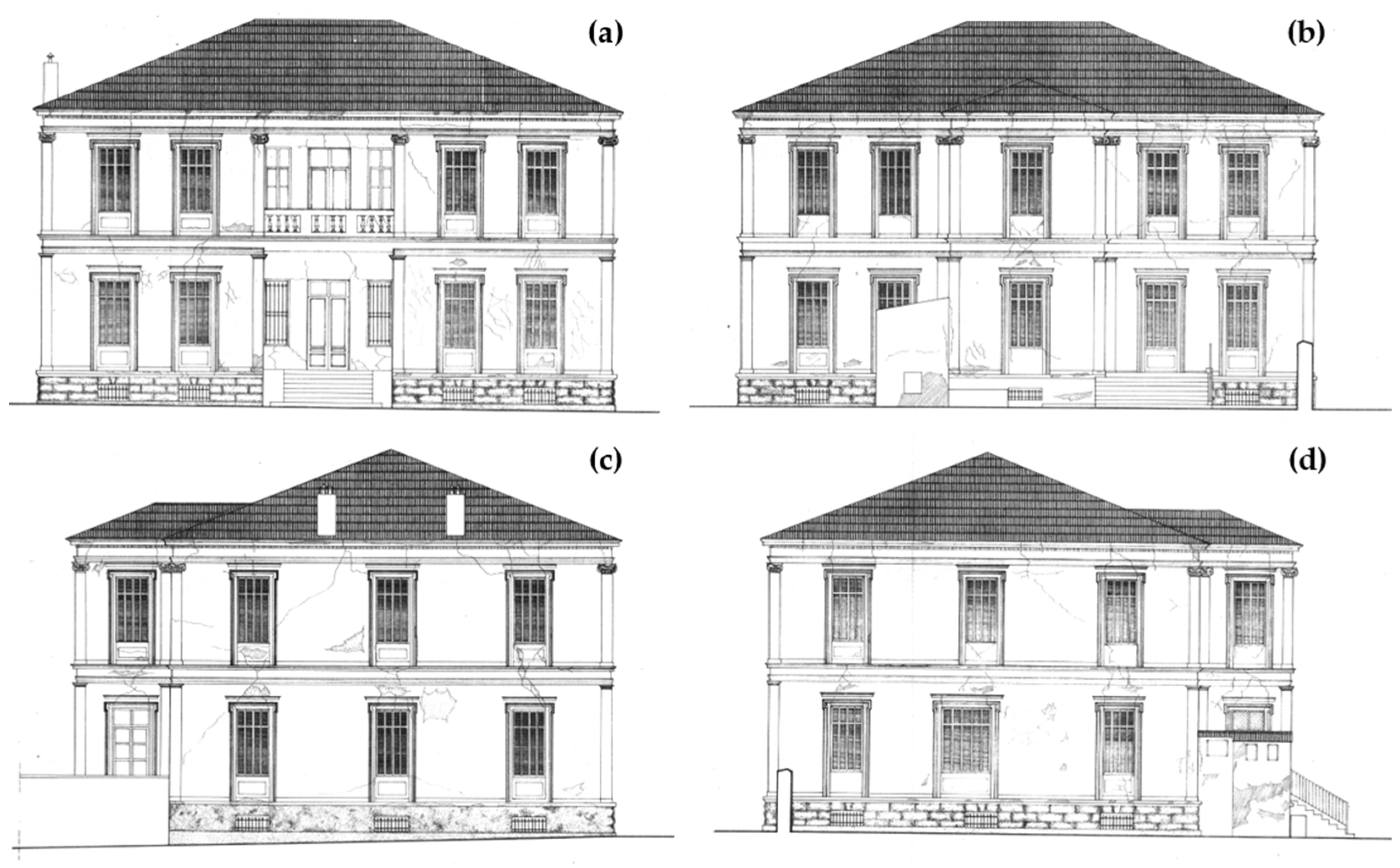
3.1.1. The Holy Monastery of the Nativity of Theotokos

The Holy Monastery of the Nativity of Theotokos, Vellas, is located approximately 30 km northwest of the city of Ioannina, near the village of Kalpaki, in the municipal unit of Pogoni. The monastery complex consists of a holy temple, surrounded by a Π-shaped arrangement of buildings (Figure 3a). These structures were built at different times using various materials, including stone and reinforced concrete. The holy temple, dating back to the 11th century, is renowned for its valuable frescoes.
For the purposes of this study, a second-tier seismic assessment was conducted on a statically independent section of the north (A’) wing of the monastery, up to the point where it connects with the central wing of the ecclesiastical school (highlighted with a red outline in Figure 3a). The examined wing, built in the 1950s, is a load-bearing stone masonry structure that accommodates the administrative offices and classrooms of the ecclesiastical school. The wing has external dimensions of 17.45 m × 34.80 m in plan and a total height of 14.70 m (measured from the floor of the first story to the roof of the fourth story, as shown in Figure 4b). The wall thickness ranges from 0.50 m to 1.00 m, with internal infill brick walls that are 0.40 m thick. The floors are made of reinforced concrete slabs, approximately 0.20 m thick. The top story is covered by a roof constructed from timber trusses, spanning the east-to-west direction of the building.

3.1.2. The Hellenic Gymnasium

The Hellenic Gymnasium, a neoclassical building constructed in 1893, is located in the center of Thessaloniki, Greece. It operated continuously as a school until the summer of 1978, when it sustained damage during a strong earthquake on 20 June 1978 (M6.5), which had its epicenter to the northeast of Thessaloniki, in the Volvi Lake region.
This two-story building, which also includes a basement and a roof, has a 20.83 m × 16.05 m floor plan, with a central corridor running from the northern to the southern façade. The building’s external height, including the roof, is 14.20 m. The configuration of all stories is illustrated in Figure 5. Prior to the 1978 Volvi earthquake, the floors were connected by a wooden staircase located at the southern end of the main corridor.
The basement walls are constructed of stone, with a thickness of 0.75 m along the perimeter and 0.65 m for the internal walls. The walls of the first and second stories are made of solid brick masonry, with thicknesses of 0.50 m and 0.40 m for the perimeter and internal walls, respectively. The floors of the first and second stories consist of double-T iron beams measuring 60 mm × 180 mm, spaced at intervals of 0.70 m. These beams are oriented along the short side of the rooms and corridors, east-west over the corridors and north-south over the classrooms. Brick arches span transversely between successive iron beams and are embedded between the upper and lower flanges of the double-T sections. The total thickness of the floors, including finishing layers, is 0.33 m at the location of the iron beams and 0.25 m at the highest point of the arches. The roof comprises timber trusses spanning the east–west direction.

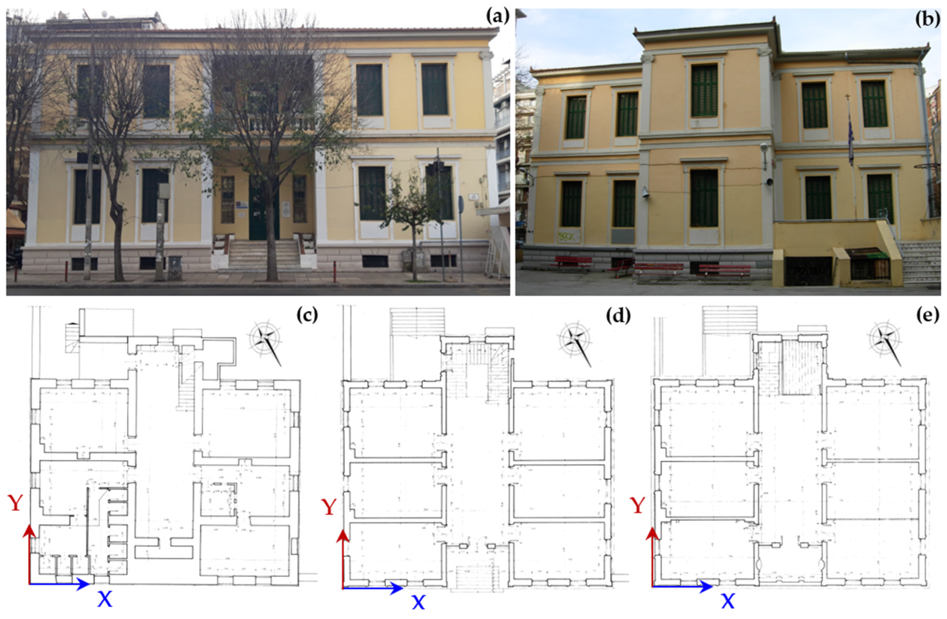
3.1.3. The Hellenic Consulate

Located near the Hellenic Gymnasium, the Hellenic Consulate was constructed in 1898. Both buildings were designed by Ernst Ziller and share a similar configuration (Figure 6). The building plan measures 19.40 m × 15.21 m, with an external height, including the roof, of 14.45 m. The basement walls are made of stone, with a thickness of 0.65 m along the perimeter and 0.55 m in the interior layout. The first-story and second-story walls are made from solid brick, with perimeter walls 0.55 m thick, and internal walls varying in thickness from 0.10 m to 0.45 m.
The floors of the first and second stories are supported by double-T iron beams. Brick arches, spanning transversely between successive iron beams, are encased between the upper and lower flanges of the double-T beams. The roof of the top story is made of timber trusses spanning the north-to-south direction of the building, with a penthouse constructed at the northeast corner featuring a concrete roof.

3.1.4. The 12th Primary School

The 12th Primary School of Thessaloniki is a two-story neoclassical building with a basement and a timber roof (Figure 7). Built in 1895, the building has served various functions throughout its history, ultimately functioning as the 12th Primary School of Thessaloniki.
The building has a square 15.25 m × 15.25 m plan, with a rectangular extension of 5.6 m × 6.1 m in the northeast corner, which houses auxiliary functions. The total height of the building, excluding the timber roof, is 12 m, with individual story heights of 2.7 m for the basement, 4.4 m for the first story, and 4.9 m for the second story. The main building is topped with a square timber-framed roof, while the rectangular extension features a terrace roof. Access to the terrace is provided via a rectangular penthouse measuring 2.3 m in height.
The basement walls are made of stone, with a thickness of 0.7 m along the perimeter and 0.6 m in the interior. The thickness of the first and second story walls follows the same pattern as the basement walls, with the first story perimeter walls being 0.46 m thick, and at specific locations the walls measure 0.7 m thick, while the interior walls are 0.23 m thick. The second story walls are 0.34 m, 0.57 m, and 0.23 m thick at the corresponding locations. The floors of the first and second stories of the main building consist of timber beams with rectangular cross-sections of 0.085 m × 0.19 m, spaced 0.4 m apart. Nailed timber boards run perpendicular to the beam axis on both the top and bottom of the beams. The ceiling of the second story in the main part of the building is supported by rectangular timber beams measuring 0.075 m × 0.12 m, spaced at 0.4 m intervals. In the rectangular extension, floors on the first and second stories, as well as the second-story ceiling, are made from double-T iron beams 0.14 m high, spaced 0.5 m apart along the Y direction. Brick arches span transversely between the beams and are encased between the upper and lower flanges.

3.2. Determination of the Seismic Hazard Index for the Examined Buildings

The seismic demand at the site of the four examined buildings is assessed by considering the characteristics of the earthquakes that damaged the structures, local geomorphological factors, soil type, and, in the case of the Ecclesiastical School of the Monastery of the Nativity of Theotokos, the probability of pounding between the examined building and the adjacent central (east) wing (see Figure 3a).

3.2.1. Seismic Action Index

The seismic action index, H1, is quantified as H1 = a·s. Furthermore, in cases where there are sufficient indications of possible local amplification of the seismic action due to the geomorphology at the site of the examined building, the value of index H1 can increase by up to 50%. In the case of the 15 October 2016 Epirus earthquake, the coefficient a is taken as 0.87 (recorded peak ground acceleration equal to 0.087 g), whereas, in the case of the 20 June 1978 Volvi earthquake, the corresponding value of a is 1.47 (recorded peak ground acceleration equal to 0.15 g). The soil type corresponding to the ground on which all buildings are founded is classified as soil type B; therefore, the value of the coefficient s is taken as 1.0 in all cases. Furthermore, due to the geomorphology at the site of the Vellas Monastery, the seismic action index is increased by 30%. Based on the above, the seismic action index is estimated as H1,Epirus = 0.87∙(1 + 0.3)·1.0 ⇒ H1,Erirus = 1.131 for the 15 October 2016 Epirus earthquake, and H1,Volvi = 1.47 for the 20 June 1978 Volvi earthquake.

3.2.2. Influence Index of Neighboring Buildings

The influence index of neighboring buildings, H2, quantifies the increase in lateral forces acting on the examined building during its seismic vibration due to pounding with adjacent buildings that lack a sufficient seismic gap, particularly in cases of unequal floor heights with strong diaphragmatic action. In the case of the Ecclesiastical School of the Monastery of the Nativity of Theotokos, the building is freestanding in the X direction (see Figure 3a); therefore, there is no risk of pounding with adjacent buildings. However, in the Y direction, the adjacent central wing shares a common number of floors but of unequal heights, posing a risk of pounding. Consequently, the H2 index for the X and Y directions of the examined building takes the values H2,Χ = 0.0 and H2,Υ = 0.8, respectively. The other three examined neoclassical buildings are freestanding in both plan directions; therefore, for those cases, H2,Χ = H2,Υ = 0.0.

3.2.3. Estimation of the Seismic Hazard Index

According to the BIPI method for masonry buildings, the seismic hazard index, H, is determined through weighted consideration of the individual indices H1 and H2, as follows: H = 0.75·H1 + 0.25·H2. In the case of the Ecclesiastical School of the Monastery of the Nativity of Theotokos, the seismic hazard indices for the X and Y directions of the floor plan are calculated as HX = ∑hi,X·Hi,X = 0.85 and HY = ∑hi,Y·Hi,Y = 1.05, whereas, in the cases of the other three examined neoclassical buildings, the corresponding indices are HX = ∑hi,X·Hi,X = 1.10 and HY = ∑hi,Y·Hi,Y = 1.10.

3.3. Determination of the Seismic Resistance Index of the Examined Builgings

The seismic resistance index of the examined buildings, R, is obtained according to Equation (7), by summing the individual resistance indices, Ri (i = 1, 2, …, 10), each of which participates with the corresponding weighting coefficient ri.
In the calculations, the first floor is considered the critical floor for the buildings in Thessaloniki. The north wing of the Vellas Monastery exhibits an irregular shape in its plan due to the significant slope of the terrain, with the first and second floors occupying only a small portion of the total area in the plan of the examined wing (see Figure 4). Since the third floor occupying the entire plan area under examination is entirely above ground level, it is considered critical for the estimation of the seismic resistance of the Vellas Monastery.
In estimating the index for the shear resistance, R1, in the case of the north wing of the Vellas Monastery, the coefficient m was set at 0.5, reflecting the characteristics of rubble stone masonry with lime mortar, the masonry type of the floor under examination. The coefficient λm was assumed to be 0.9, based on the satisfactory degree of connection between the masonry units. The sum of the cross-sectional areas of the masonry walls, ∑Aw, is calculated to be 42.41 m2 in the X direction and 46.24 m2 in the Y direction. Additionally, the plan area of the examined floor level, A, is 461.21 m2, and the parameter n is set at 2. As a result, in the X direction, the R1 index equals 0.25, and in the Y direction, it is 0.27. In the case of the three other examined buildings, with walls on their critical floors made of solid bricks, connected with lime-cement mortar, exhibiting good bonding and no mortar disintegration, the coefficient m was set at 1.0 and the coefficient λm was assumed to be 1.0. For the Hellenic Gymnasium, ∑Aw,X and ∑Aw,Y equal 20.94 m2 and 19.85 m2, respectively, A is 345.62 m2 and n is 2, resulting in R1,Χ = 0.36 and R1,Υ = 0.34. In the case of the Hellenic Consulate, ∑Aw,X = 11.85 m2, ∑Aw,Y= 22.96 m2, A = 286.90 m2, and n = 2; therefore, R1,Χ = 0.25 and R1,Υ = 0.48. For the 12th Primary School, ∑Aw,X is 13.97 m2, ∑Aw,Y is 17.60 m2, A is 267.77 m2, and n is 2; therefore, R1,Χ equals 0.31 and R1,Υ equals 0.39.
To estimate the index for openings at load-bearing masonry walls on the critical floor, the total lengths of the openings were calculated for each building in both the X and Y plan directions. For the north wing of the Vellas Monastery, the total lengths of the openings were found to be 19.50 m in the X direction and 28.55 m in the Y direction, while the total lengths of the load-bearing walls were 86.03 m and 96.64 m, respectively. In the case of the Hellenic Gymnasium, the total lengths of the openings were 14.41 m in the X direction and 18.46 m in the Y direction, whereas the corresponding lengths of the load-bearing walls were 40.18 m and 68.36 m. For the Hellenic Consulate, the openings measured 10.15 m in the X direction and 20.15 m in the Y direction, while the load-bearing walls were 31.45 m and 68.80 m, respectively. Finally, for the 12th Primary School, the total lengths of the openings were 15.80 m in the X direction and 22.00 m in the Y direction, and the load-bearing walls measured 48.20 m and 73.05 m, respectively. Consequently, by applying Equation (4), the R2 indices in the X and Y directions (R2,X and R2,Y) were determined as follows: for the Vellas Monastery, R2,X = 0.90 and R2,Y = 0.74; for the Hellenic Gymnasium, R2,X = 0.62 and R2,Y = 0.79; for the Hellenic Consulate, R2,X = 0.68 and R2,Y = 0.74; and for the 12th Primary School, R2,X = 0.67 and R2,Y = 0.73.
Regarding the estimation of the index for horizontal ties, the value of R3 for the north wing of the Vellas Monastery was conservatively assumed to be 0.5. This assumption was necessitated by the conditions during the building inspection, where it was not feasible to perform investigative section cuts in the masonry to determine the presence or absence of adequate horizontal ties within the load-bearing masonry walls. For the other three buildings, R3 was taken as 1.0, since horizontal ties were observed both above wall openings and at all floor and roof levels.
For the estimation of the diaphragm action index, in the case of the examined wing of the Vellas Monastery, the arrangement of load-bearing walls in plan view is asymmetrical (see Figure 4), and the floors of the examined building wing consist of reinforced concrete slabs, which provide a strong degree of connection between the diaphragms and the underlying walls. Consequently, according to Table 3, the R4 index for the examined building wing of the Vellas Monastery is 0.70. For the Hellenic Gymnasium and the Hellenic Consulate, the R4 index is taken as 0.75, since the arrangement of the load-bearing walls in the direction perpendicular to the axis of symmetry of the floor plans is partially symmetrical (see Figure 5 and Figure 6). Furthermore, on the top floor of both buildings, which is the most critical regarding the degree of diaphragm action provided by the horizontal structural elements, the diaphragm stiffness ensured by the wooden roofs and their connection to the underlying walls is considered moderate. For the 12th Primary School, R4 is taken as 0.40, since the presence of wooden floors on the first two floors and a wooden roof on the top floor is deemed to provide a weak degree of diaphragm action, and the arrangement of the load-bearing walls in the floor plan is asymmetrical (see Figure 7).
The index for openings near wall corners in the case of the north wing of the Vellas Monastery was estimated according to Equation (5). The parameter λ was set to 0.5, since there are a total of 10 masonry piers (α = 10), each shorter than 1.0 m, forming external corners in both principal plan directions along the height of the examined building wing (see Figure 4). The number of external corners across all stories, γ, is 27, and the sum of the lengths of all piers shorter than 1.0 m forming external corners, ∑lw, is 3.74 m. Additionally, a 50% reduction in the value of parameter α was considered, due to the strong diaphragm action provided at the building’s floor and roof levels through the presence of reinforced concrete slabs. Consequently, index R5 was estimated to be −0.62. For the other three buildings examined, index R5 is taken as 0.00, since there are no walls shorter than 1.0 m forming external corners.
Regarding the index for damages to load-bearing walls, all examined buildings prior to the earthquakes that caused damage to them were in good condition. Up to that point, the structures had not experienced strong earthquakes, and their function ensured continuous maintenance. Consequently, the R6 index for all the examined buildings before the earthquakes that damaged them is estimated to be 0.75.
Regarding the type of connection between transverse walls, as observed during the inspection of all buildings, the brick units at the wall intersections are interlocked, therefore, in all cases, index R7 is considered to be equal to 1.00.
To calculate the index for out-of-plane loading of perimeter walls, Table 5 presents, for each group of perimeter walls with the same thickness, t, at all stories of the examined buildings, the longest length, , of the wall between two successive connections with transverse walls. For each case, the index R8 is calculated according to Equation (6), and the corresponding values are presented in the last column of Table 5. Evidently, the minimum value of the R8 index is 0.24 for the examined building wing of the Vellas Monastery, 0.54 for the Hellenic Gymnasium, 0.25 for the Hellenic Consulate, and 0.37 for the 12th Primary School.
Regarding the index for regularity in floor plans, R9, all buildings except for the Hellenic Consulate have a complex floor shape. For these three buildings, the degree of irregularity in plan is determined for all floors. Table 6 summarizes the process of characterizing the floors of the three buildings based on the parameters ∑AE, AE,max, and Atot. Based on the values of the ratios ∑AE/Atot and AE,max/Atot, in the case of the north wing of the Vellas Monastery, the first and fourth floors can be characterized as regular in floor plan, the second floor is characterized as partially regular, and the third floor is characterized as irregular. Given that the third floor is the critical floor among the four floors of the building, the structure can be considered irregular in floor plan; therefore, the R9 index is estimated to be 0.50. In the cases of the Hellenic Gymnasium and the 12th Primary School, the values of the ratios ∑AE/Atot and AE,max/Atot are lower than 0.15 in all stories; therefore, they are characterized as regular in floor plan, resulting in an R9 value of 1.00. In the case of the Hellenic Consulate, which has an orthogonal shape in plan, Lmax equals 19.00 m and Lmin equals 15.20 m; therefore, λ = 1.25, which results in an R9 value of 1.00.
Regarding the determination of the index for regularity in height, the difference in lateral stiffness between neighboring floors is calculated through the variation in the sum of the wall cross-section areas (∑Aw) in each of the two principal plan directions (Table 7). As presented in Table 8, the difference in ∑Aw ranges, in the case of the north wing of the Vellas Monastery, is between 1% and 45% in the X plan direction and between 15% and 59% in the Y plan direction; in the case of the Hellenic Gymnasium, the range is between 20% and 43% in the X plan direction and between 1% and 41% in the Y plan direction; in the case of the Hellenic Consulate, it is between 2% and 33% in the X plan direction and between 5% and 20% in the Y plan direction; and, in the case of the 12th Primary School, it is between 16% and 53% in the X plan direction and between 21% and 42% in the Y plan direction. Furthermore, since the examined building wing of the Vellas Monastery is constructed on sloping ground and the height difference between the lowest and highest ground levels is two stories (see Figure 4), the building can be classified as partially regular in height. Based on those differences in wall cross-section areas, the index R10 is considered equal to 0.50 for the examined building wing of the Vellas Monastery, equal to 0.75 for the Hellenic Gymnasium and the Hellenic Consulate, and equal to 0.50 for the 12th Primary School.
The earthquake resistance index, R = ∑(Ri·ri), of the four examined buildings is calculated by considering the values of the individual seismic resistance indices Ri and their corresponding weighting factors ri, as summarized in Table 9. The value of R is determined as 0.351 for the north wing of the Vellas Monastery, 0.603 for the Hellenic Gymnasium, 0.559 for the Hellenic Consulate, and 0.535 for the 12th Primary School.

3.4. Determination of the Control Priority Index λ

The BIPI method for masonry buildings is completed in its third step with the determination of the building’s control priority index as the ratio of seismic action to seismic resistance in the two principal plan directions of the examined buildings, λX = HX/R and = and λΥ = HΥ/R. For the north wing of the Vellas Monastery, λX = 0.85/0.351 = 2.42 and λΥ = 1.05/0.351 = 2.99. In the case of the Hellenic Gymnasium, λX = λΥ = 1.10/0.603 = 1.82; for the Hellenic Consulate, λX = λΥ = 1.10/0.559 = 1.97; and, for the 12th Primary School, λX = λΥ = 1.10/0.535 = 2.06.
As revealed by the application of the method, the value of the control priority index for all four masonry buildings is significantly higher than one, indicating serious seismic inadequacy and the necessity of conducting a third-stage assessment. Furthermore, according to the BIPI method, the building that sustained the most earthquake damage is the examined building wing of the Vellas Monastery (max λ = 2.99), followed by the 12th Primary School (λ = 2.06), the Hellenic Consulate (λ = 1.97), and, lastly, the Hellenic Gymnasium which suffered the least earthquake damage (λ = 1.82). It is worth noting that the seismic inadequacy of the three buildings in Thessaloniki, as determined through the application of the BIPI method, is significantly higher when compared to the results derived from detailed third-tier seismic assessments for the buildings in Thessaloniki ([50,51]).

4. Evaluation of the Accuracy of the Building Inspection Priority Index Method

The accuracy of the Building Inspection Priority Index (BIPI) method is evaluated by comparing the results derived from its application to the damage developed in the examined buildings after their seismic excitation.

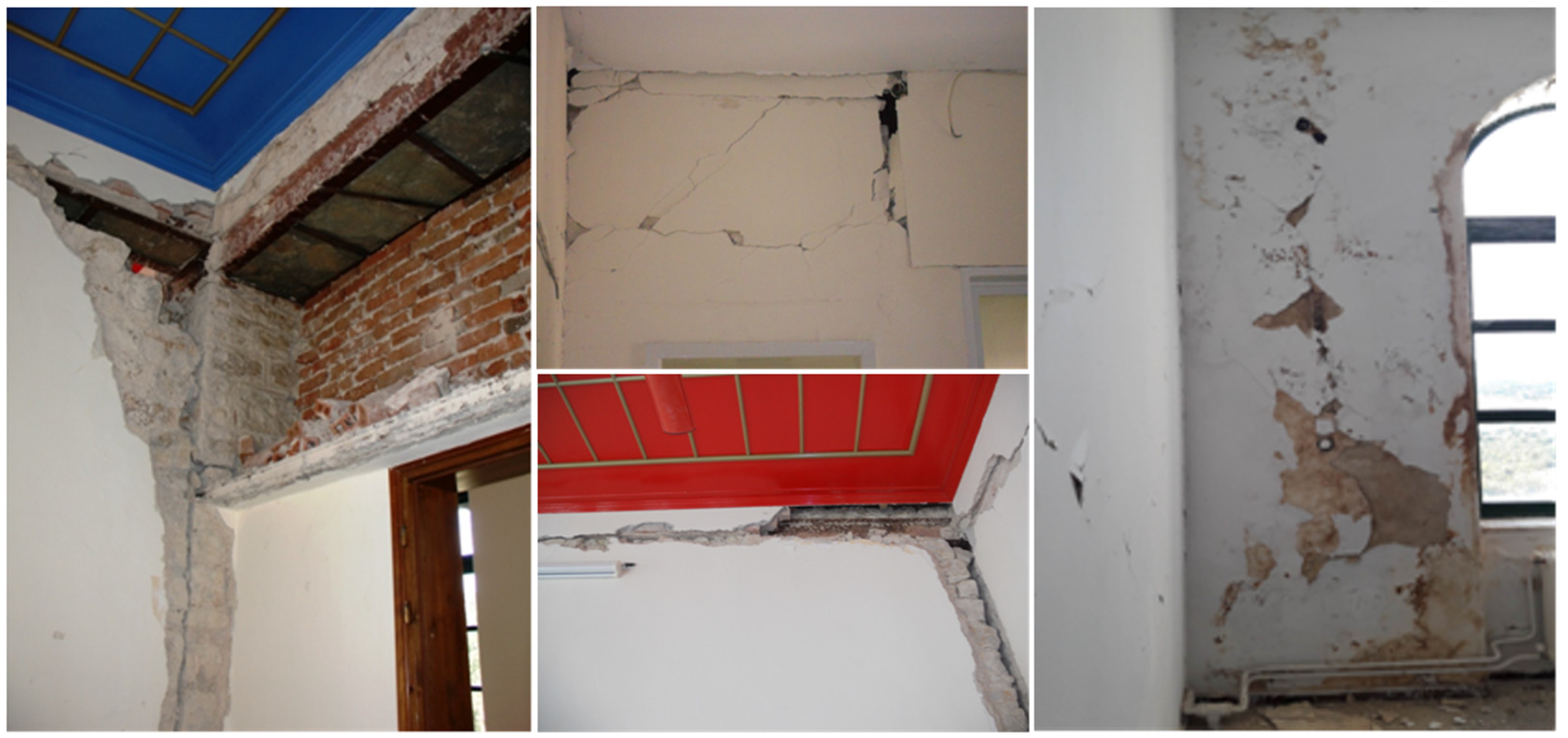
4.1. Seismic Response of the North Wing of the Vellas Monastery During the 15 October 2016 Epirus Earthquake

During the earthquake of 15 October 2016, the north wing of the Vellas Monastery sustained significant structural damage. Specifically, around the stairwell, failures were observed in the connection between the masonry walls, particularly at the corners and lintels of the openings. In addition, severe cracking and displacements were observed in sections of the masonry beneath the roof of the third floor and at the corners. Most of the cracks were flexural, although a few shear cracks also developed. Plaster detached in many areas within the stairwell, and several closets integrated to the walls experienced displacements and failures.
On the first floor, plaster disintegration occurred, and shear cracks appeared in the thin piers as well as in the connections between intersecting masonry walls. Additionally, there was damage to the plaster, along with through cracks in the masonry. Localized damage also developed due to the out-of-plane bending of the masonry. On the second floor, the infill wall suffered disintegration, and bricks fell off due to the out-of-plane vibration of the masonry. A few shear cracks appeared in the piers of the external masonry walls due to in-plane seismic forces. Furthermore, cracks developed due to the differential settlement of the eastern extension of the north wing.
Most of the damage occurred on the third and fourth floors, where increased deformations were observed during the earthquake. These damages included cracking and detachment of plaster, damage to stone masonry walls, falling plaster, cross and vertical cracks, as well as the detachment of brickwork from the surrounding frames (Figure 8).

4.2. Seismic Response of the Thessaloniki Buildings During the 20 June 1978 Volvi Earthquake

During the earthquake of 20 June 1978, the Hellenic Gymnasium sustained multiple cracks, ranging from minor to severe, and through cracks in the internal load-bearing walls, primarily above the openings. Additionally, detachment of the internal masonry occurred at the connections between the internal and external walls, as well as at locations where openings had been closed. Cracking of the brick cornice at the building’s roofline was observed, along with minor cracking in the external masonry (Figure 9). Further damages included cracks and detachment of decorative frames around windows, doors, and landings, as well as displacement and breakage of roof tiles.
During the same earthquake, the Hellenic Consulate experienced significant damage to the load-bearing walls, particularly in the stairwell, where the upper section of the external wall at the northeastern corner exhibited a 4.5 cm deviation and intense through cracks. In this area, settlement of the roof of the second floor resulted in the nearly complete disintegration of the walls of the upper attic. Secondary damages were observed in the load-bearing walls at the positions of the lintels, mostly in the form of severe cracking below the cantilevered sections, as well as detachment of the structural system from the partition walls. Cracks were observed in the walls of the second floor along the shorter dimension of the building’s plan, beneath the attic addition. Corresponding walls on the first floor exhibited severe cracks at the lintel positions, which continued down to the base of the windows on the second floor. Finally, some sections of the parapets and parts of the building’s roof suffered collapses.
Last, the 12th Primary School, following the inspection conducted after the strong earthquake of 20 June 1978, was found to have performed exceptionally well, with no damage to the load-bearing structure.

4.3. Evaluation of the BIPI Method

The application of the BIPI method for masonry buildings, with the same peak ground acceleration as that which caused damage to the four examined buildings, showed that the most vulnerable building was the north wing of the Vellas Monastery. For this building, the BIPI method indicated an excess of the seismic capacity of the structure by 242% in the X direction and 299% in the Y direction. The increased value of the index (λ = 2.99) is consistent with the development of damage in the building (λ > 1.0 is linked to exceeding the seismic capacity of a building and the development of damage), although the increased value of λ does not correlate with the extent and severity of the damage developed in the north wing of the Vellas Monastery during the Epirus earthquake on 15 October 2016 (M5.3).
Regarding the examined buildings in Thessaloniki, the increased values of λ correspond to the damage observed during the Volvi earthquake on 20 June 1978 (M 6.5) for both the Hellenic Gymnasium (λ = 1.82) and the Hellenic Consulate (λ = 1.97), although, as in the case of the north wing of the Vellas Monastery, the magnitude of the λ values does not align with the extent and severity of the damage developed in these two buildings. In the case of the seismic response of the 12th Primary School during the same earthquake, there is no correlation between the 206% excess of the seismic capacity of the structure (λ = 2.06), according to the BIPI method, and the actual seismic response of the respective building, which suffered no damage to its load-bearing structure.
Of course, as stated in the BIPI method, the λ index does not have absolute physical significance, and the goal of the method is to rank the examined buildings based on their seismic vulnerability. With this criterion in mind, the small differences between the λ values for the Hellenic Gymnasium and the Hellenic Consulate are confirmed by the actual seismic responses of the buildings, both of which sustained damage of similar severity to their load-bearing structures during the Volvi earthquake on 20 June 1978. However, the same level of damage was sustained by the north wing of the Vellas Monastery during the Epirus earthquake on 15 October 2016, which does not agree with the comparison of the seismic assessment results of these three buildings obtained by the BIPI method, according to which the north wing of the Vellas Monastery clearly appears more vulnerable than the Hellenic Gymnasium and the Hellenic Consulate. Finally, the ranking of the 12th Primary School in terms of seismic vulnerability, compared to the other three examined buildings, is incorrect according to the BIPI method, as it is ranked as the second-most seismically vulnerable building, while, in reality, it is the building with the best seismic response among the four examined buildings.
Given that second-tier seismic assessment procedures, in addition to ranking the buildings under consideration based on their seismic vulnerability, also provide a preliminary estimate of their seismic capacity ([2,3,52], etc.), the BIPI method is considered more suitable for first-tier rather than second-tier seismic assessment of masonry buildings. In order to be used as a second-tier procedure, the current pre-standard of the method must be improved in terms of both the evaluation of seismic demand and the estimation of seismic capacity for the buildings under assessment. Regarding the evaluation of seismic demand for the examined building, the dynamic response of the building to the earthquake scenario used for the assessment must be considered; in the frmework of a second-tier seismic assessment procedure, this can be done by taking into account the deformed shape of the building at the instant of its peak seismic response ([25,52]). As for the estimation of the seismic capacity of the buildings under assessment, the method must account for the significant variation in the mechanical properties of masonry commonly observed in existing masonry buildings ([42,43,44,45]). Furthermore, it should allow for the individualized consideration of the influence that geometric and mechanical characteristics have on the overall seismic capacity of each building, rather than relying on fixed values for weighting coefficients applicable to all building cases, regardless of their unique structural characteristics.

5. Conclusions

In this study, the reliability of the Building Inspection Priority Index (BIPI) method for the second-tier seismic assessment of masonry structures [46] is evaluated. This method requires knowledge of the basic geometric characteristics of the masonry buildings under examination, based on which elementary calculations are performed to quantitatively determine approximate indices for the seismic demand and seismic capacity of the buildings. Through this process, the masonry buildings are prioritized based on their seismic vulnerability, and their priority for detailed seismic capacity determination using third-tier assessment methods is established.
The evaluation of the BIPI method for masonry structures was carried out by comparing the results obtained from its application to four existing masonry buildings in Epirus and Central Macedonia, Greece, with the damage observed at those buildings during past strong earthquakes. In terms of applicability, the method is relatively simple for practitioners to use, requires straightforward calculations that can be easily performed by specialized structural engineers, and, once the survey of the building under examination is completed, the calculation of the control priority index—which ranks the building in terms of seismic capacity—can be completed in a short period of time. In terms of result accuracy, the method tends to underestimate the seismic capacity of the buildings under examination, which is a conservative approach, given the empirical nature of the method. Regarding the prioritization of the examined buildings based on their seismic vulnerability—which is the primary objective of the method—the BIPI method did not yield reliable results. It showed significant discrepancies in the seismic vulnerability of buildings that actually exhibited similar seismic behavior, while it categorized a building that did not sustain damage to its structural system as one with high seismic vulnerability. The current pre-standard for the BIPI method appears to be more suitable for first-tier seismic assessments. For its application as a second-tier seismic assessment procedure, improvements are required in both the evaluation of seismic demand and the estimation of seismic capacity for the buildings under assessment.

Author Contributions

Conceptualization, S.I.P., A.E.G. and V.A.L.; Writing—original draft, S.I.P., A.E.G. and V.A.L.; Writing—review & editing, S.I.P., A.E.G. and V.A.L.; Supervision, S.I.P. All authors have read and agreed to the published version of the manuscript.

Funding

This research received no external funding.

Data Availability Statement

The original contributions presented in this study are included in the article. Further inquiries can be directed to the corresponding author(s).

Acknowledgments

The seismic assessment of the ecclesiastical school of the Holy Monastery of the Nativity of Theotokos, Vellas, was funded by the project ‘Consequences of Strong Ground Motion on the Built Environment—Seismic Assessment of Selected Structures’ under the act titled ‘Earthquake Disasters Management Integrated System’ (ERMIS) of the European Interreg Program Italy-Greece 2014–2020. All individuals included in this section have consented to the acknowledgement.

Conflicts of Interest

The authors declare no conflict of interest.

References

  1. Federal Emergency Management Agency (FEMA). Rapid Visual Screening of Buildings for Potential Seismic Hazards: A Handbook, 3rd ed.; Government Printing Office: Washington, DC, USA, 2015.
  2. American Society of Civil Engineers (ASCE). Seismic Evaluation and Retrofit of Existing Buildings; ASCE/SEI 41-23; ASCE: Reston, VA, USA, 2023; ISBN 978-0-7844-8476-0. [Google Scholar]
  3. New Zealand Society for Earthquake Engineering (NZSEE); Structural Engineering Society (SESOC); NZ Geotechnical Society (NZGS). The Seismic Assessment of Existing Buildings–Technical Guidelines for Engineering Assessments, 2017. Available online: http://EQ-Assess.org.nz (accessed on 10 December 2024).
  4. Sextos, A.G.; Kappos, A.J.; Stylianidis, K.C. Computer-aided pre- and post-earthquake assessment of buildings involving database compilation, GIS visualization, and mobile data transmission. Comput.-Aided Civ. Infrastruct. Eng. 2008, 23, 59–73. [Google Scholar] [CrossRef]
  5. Karbassi, A.; Nollet, M.J. Development of an index assignment procedure compatible with the regional seismicity in the province of Quebec for the rapid visual screening of existing buildings. Can. J. Civ. Eng. 2008, 35, 925–937. [Google Scholar] [CrossRef]
  6. Arya, A.S.; Agarwal, A. Rapid Visual Screening of Masonry Buildings; Technical Report; National Disaster Management Division, Ministry of Home Affairs, Government of India: New Delhi, India, 2006.
  7. Sucuoğlu, H.; Yazgan, U.; Yakut, A. A screening procedure for seismic risk assessment in urban building stocks. Earthq. Spectra 2007, 23, 441–458. [Google Scholar] [CrossRef]
  8. Earthquake Planning and Protection Organization (EPPO). First-Tier Seismic Assessment of Buildings, 6th ed.; EPPO: Athens, Greece, 2024.
  9. Lourenço, P.B.; Oliveira, D.V.; Leite, J.C.; Ingham, J.M.; Modena, C.; da Porto, F. Simplified indexes for the seismic assessment of masonry buildings: International database and validation. Eng. Fail. Anal. 2013, 34, 585–605. [Google Scholar] [CrossRef]
  10. Chieffo, N.; Clementi, F.; Formisano, A.; Lenci, S. Comparative fragility methods for seismic assessment of masonry buildings located in Muccia (Italy). J. Build. Eng. 2019, 25, 100813. [Google Scholar] [CrossRef]
  11. D’Amato, M.; Laguardia, R.; Di Trocchio, G.; Coltellacci, M.; Gigliotti, R. Seismic Risk Assessment for Masonry Buildings Typologies from L’Aquila 2009 Earthquake Damage Data. J. Earthq. Eng. 2020, 26, 4545–4579. [Google Scholar] [CrossRef]
  12. Tatangelo, M.; Audisio, L.; D’Amato, M.; Gigliotti, R. Seismic risk analysis on masonry buildings damaged by L’Aquila 2009 and Emilia 2012 earthquakes. Procedia Struct. Integr. 2023, 44, 990–997. [Google Scholar] [CrossRef]
  13. Rosti, A.; Rota, M.; Penna, A. Clustering of empirical damage data for the vulnerability classification of the Italian residential building stock. Procedia Struct. Integr. 2023, 44, 83–90. [Google Scholar] [CrossRef]
  14. Rosti, A.; Rota, M.; Penna, A. Empirical fragility curves for Italian URM buildings. Bull. Earthq. Eng. 2021, 19, 3057–3076. [Google Scholar] [CrossRef]
  15. Zuccaro, G.; Perelli, F.L.; De Gregorio, D.; Cacace, F. Empirical vulnerability curves for Italian mansory buildings: Evolution of vulnerability model from the DPM to curves as a function of accelertion. Bull. Earthq. Eng. 2021, 19, 3077–3097. [Google Scholar] [CrossRef]
  16. Federal Emergency Management Agency (FEMA); American Society of Civil Engineers (ASCE). Handbook for the Seismic Evaluation of Buildings: A Prestandard; FEMA 310; Federal Emergency Management Agency (FEMA): Washington, DC, USA, 1998.
  17. Calvi, G.M. A displacement-based approach for vulnerability evaluation of classes of buildings. J. Earthq. Eng. 1999, 3, 411–438. [Google Scholar] [CrossRef]
  18. Lourenço, P.B.; Roque, J. Simplified indexes for the seismic vulnerability of ancient masonry buildings. Struct. Mason. Earthq. 2006, 20, 200–208. [Google Scholar] [CrossRef]
  19. Vamvatsikos, D.; Pantazopoulou, S. Simplified Mechanical Model to Estimate the Seismic Vulnerability of Heritage Unreinforced Masonry Buildings. J. Earthq. Eng. 2016, 20, 298–325. [Google Scholar] [CrossRef]
  20. Di Gennaro, L.; de Cristofaro, M.; Loreto, G.; Minutolo, V.; Olivares, L.; Zona, R.; Frunzio, G. In-situ load testing of an ancient masonry structure using fibre optics. Structures 2024, 70, 107567. [Google Scholar] [CrossRef]
  21. Guadagnuolo, M.; Di Gennaro, L.; Basile, A.; De Matteis, G. Simplified methods for the evaluation of mechanical properties of tuff masonry walls in Campania (Italy). Procedia Struct. Integr. 2023, 44, 878–885. [Google Scholar] [CrossRef]
  22. Sreejith, P.P.; Sivan, P.P.; Praveen, A.; Gajendran, C.; Nisha, V. Simplified Method for Shear Strength Prediction of Confined Masonry Walls Subjected to in Plane Loads. Procedia Technol. 2016, 24, 155–160. [Google Scholar] [CrossRef]
  23. Earthquake Planning and Protection Organization (EPPO). KADET: Code for Assessment and Structural Interventions in Masonry Buildings; EPPO: Athens, Greece, 2023.
  24. EN 1998-3; Eurocode 8: Design of Structures for Earthquake Resistance—Part 3: Assessment and Retrofitting of Buildings. CEN: Brussels, Belgium, 2005.
  25. Pardalopoulos, S.I.; Pantazopoulou, S.J. Methodology for practical seismic assessment of unreinforced masonry buildings with historical value. Earthq. Eng. Struct. Dyn. 2017, 46, 2793–2810. [Google Scholar] [CrossRef]
  26. Pardalopoulos, S.I.; Karantoni, F.V.; Pantazopoulou, S.J. Practical assessment of the seismic behavior of a confined masonry system. Soil Dyn. Earthq. Eng. 2019, 127, 105831. [Google Scholar] [CrossRef]
  27. Croce, P.; Landi, F.; Formichi, P.; Beconcini, M.L.; Puccini, B.; Zotti, V. Non-linear methods for the assessment of seismic vulnerability of masonry historical buildings. In Protection of Historical Constructions; Vayas, I., Mazzolani, F.M., Eds.; Lecture Notes in Civil Engineering; Springer: Cham, Switzerland, 2022; Volume 209, pp. 651–670. [Google Scholar] [CrossRef]
  28. Kappos, A.; Penelis, G.; Drakopoulos, C. Evaluation of simplified models for lateral load analysis of unreinforced masonry buildings. J. Struct. Eng. 2002, 128, 890–897. [Google Scholar] [CrossRef]
  29. Lagomarsino, S.; Galasco, A.; Penna, A. Pushover and dynamic analysis of 3D masonry buildings by means of a non-linear macro-element model. In Proceedings of the International Conference on Earthquake Loss Estimation and Risk Reduction, Bucharest, Romania, 24–26 October 2002. [Google Scholar]
  30. Lagomarsino, S.; Cattari, S. PERPETUATE guidelines for seismic performance-based assessment of cultural heritage masonry structures. Bull. Earthq. Eng. 2015, 13, 13–47. [Google Scholar] [CrossRef]
  31. Salonikios, T.; Karakostas, C.; Lekidis, V.; Anthoine, A. Comparative inelastic pushover analysis of masonry frames. Eng. Struct. 2003, 25, 1515–1523. [Google Scholar] [CrossRef]
  32. Galasco, A.; Lagomarsino, S.; Penna, A.; Resemini, S. Non-linear seismic analysis of masonry structures. In Proceedings of the 13th World Conference on Earthquake Engineering, Vancouver, BC, Canada, 1–6 August 2004. [Google Scholar]
  33. Galasco, A.; Lagomarsino, S.; Penna, A. On the use of pushover analysis for existing masonry buildings. In Proceedings of the 1st European Conference on Earthquake Engineering and Seismology, Geneva, Switzerland, 3–8 September 2006. [Google Scholar]
  34. Rizzano, G.; Sabatino, R. An equivalent frame model for seismic analysis of masonry structures. In Proceedings of the 8th National Conference on Seismology and Earthquake Engineering, Aveiro, Portugal, 20–23 October 2010. [Google Scholar]
  35. Sabatino, R.; Rizzano, G. A simplified approach for the seismic analysis of masonry structures. Open Constr. Build. Technol. J. 2011, 5, 97–104. [Google Scholar]
  36. Lagomarsino, S.; Giovinazzi, S. Macroseismic and mechanical models for the vulnerability and damage assessment of current buildings. Bull. Earthq. Eng. 2006, 4, 415–443. [Google Scholar] [CrossRef]
  37. Borzi, B.; Crowley, H.; Pinho, R. Simplified pushover-based earthquake loss assessment (SP-BELA) method for masonry buildings. Int. J. Archit. Herit. 2008, 2, 353–376. [Google Scholar] [CrossRef]
  38. Ferreira, T.M.; Costa, A.A.; Vicente, R.; Varum, H. A simplified four-branch model for the analytical study of the out-of-plane performance of regular stone URM walls. Eng. Struct. 2015, 83, 140–153. [Google Scholar] [CrossRef]
  39. Giordano, N.; De Luca, F.; Sextos, A. Out-of-plane closed-form solution for the seismic assessment of unreinforced masonry schools in Nepal. Eng. Struct. 2020, 203, 109548. [Google Scholar] [CrossRef]
  40. Di Gennaro, L.; Guadagnuolo, M.; Monaco, M. Rocking Analysis of Towers Subjected to Horizontal Forces. Buildings 2023, 13, 762. [Google Scholar] [CrossRef]
  41. Pingaro, N.; Buzzetti, M.; Milani, G. Advanced FE nonlinear numerical modeling to predict historical masonry vaults failure: Assessment of risk collapse for a long span cloister vault heavily loaded at the crown by means of a general-purpose numerical protocol. Eng. Fail. Anal. 2025, 167, 109070. [Google Scholar] [CrossRef]
  42. Parisi, F.; Augenti, N. Uncertainty in seismic capacity of masonry buildings. Buildings 2012, 2, 218–230. [Google Scholar] [CrossRef]
  43. Croce, P.; Landi, F.; Formichi, P. Probabilistic seismic assessment of existing masonry buildings. Buildings 2019, 9, 237. [Google Scholar] [CrossRef]
  44. Rota, M.; Penna, A.; Magenes, G. A framework for the seismic assessment of existing masonry buildings accounting for different sources of uncertainty. Earthq. Eng. Struct. Dyn. 2014, 43, 1045–1066. [Google Scholar] [CrossRef]
  45. Borri, A.; Corradi, M.; Castori, G.; De Maria, A. A method for the analysis and classification of historic masonry. Bull Earthq. Eng. 2015, 13, 2647–2665. [Google Scholar] [CrossRef]
  46. Earthquake Planning and Protection Organization (EPPO). Second-Tier Pre-Seismic Assessment of Masonry Buildings; EPPO: Athens, Greece, 2018.
  47. Vintzilaiou, E.; Tasios, T. Assessment of the Relative Seismic Risk of Historical Masonry Buildings; Seminar proceedings; Technical Chamber of Greece: Athens, Greece. (In Greek)
  48. EN 1998-1; Eurocode 8: Design of Structures for Earthquake Resistance—Part 1: General Rules, Seismic Actions and Rules for Buildings. CEN: Brussels, Belgium, 2004.
  49. EN 1996-1-1; Eurocode 6: Design of Masonry Structures—Part 1-1: General Rules for Reinforced and Unreinforced Masonry Structures. CEN: Brussels, Belgium, 2005.
  50. Pardalopoulos, S.I.; Pantazopoulou, S.J.; Kontari, M.T. Rapid seismic assessment procedure of masonry buildings with historic value. In Seismic Assessment, Behavior and Retrofit of Heritage Buildings and Monuments; Psycharis, I., Pantazopoulou, S., Papadrakakis, M., Eds.; Computational Methods in Applied Sciences; Springer: Cham, Switzerland, 2015; pp. 113–137. [Google Scholar] [CrossRef]
  51. Pardalopoulos, S.I.; Pantazopoulou, S.J.; Ignatakis, C.E. Practical seismic assessment of unreinforced masonry historical buildings. Earthq. Struct. 2016, 11, 195–215. [Google Scholar] [CrossRef]
  52. Pardalopoulos, S.I.; Pantazopoulou, S.J. Rapid seismic assessment of two four-storey R.C. test buildings. Bull Earthq. Eng 2019, 17, 1379–1406. [Google Scholar] [CrossRef]
Figure 1. Different types of masonry buildings: (a) neoclassical; (b) industrial; (c) cultural; (d) urban.
Infrastructures 10 00118 g001
Figure 2. Diagrammatic representation of the implementation process of the Building Inspection Priority Index method for masonry structures.
Infrastructures 10 00118 g002
Figure 3. (a) Floor plan of the Vellas Monastery highlighting the wing under investigation; (b) front west façade; (c) front south façade; (d,e) different views of the north façade.
Infrastructures 10 00118 g003
Figure 4. (a1a4) Floor plans of the 1st, 2nd, 3rd and 4th story, respectively, of the building wing under investigation; (b) section cut of the examined building wing.
Infrastructures 10 00118 g004
Figure 5. The Hellenic Gymnasium: (a) North façade; (b) south Façade; (ce) floor plans of the basement, the 1st and the 2nd stories, respectively.
Infrastructures 10 00118 g005
Figure 6. The Hellenic Consulate: (a) North-west façade; (b) south-east facade; (ce) floor plans of the basement, the 1st and the 2nd stories, respectively.
Infrastructures 10 00118 g006
Figure 7. The 12th Primary School: (a) North and west façades; (b) south facade; (ce) floor plans of the basement, the 1st and the 2nd stories, respectively.
Infrastructures 10 00118 g007
Figure 8. Representative cases of structural element damage in the north wing of the Holy Monastery of the Nativity of Theotokos, Vellas, after the Epirus earthquake of 15 October 2016 (M5.3).
Infrastructures 10 00118 g008
Figure 9. Damages developed at the Hellenic Gymnasium during the Volvi earthquake of 20 June 1978 (M6.5): (a) North façade; (b) south façade; (c) east façade; (d) west façade.
Infrastructures 10 00118 g009
Table 1. Test summary and predicted failure mechanism.
Seismic
Hazard
Zone
Coefficient
a
Soil Category/Coefficient s
AB, CDES1, S2 *
0.851.001.151.25-
Z11.61.361.601.842.00-
Z22.42.042.402.763.00-
Z23.63.063.604.144.50-
* Buildings on soil categories S1 or S2 are subject to third-tier seismic assessment.
Table 2. Values of the influence index of neighboring buildings, H2.
Characteristics of Neighboring BuildingsH2
Freestanding building or adjacent with sufficient seismic gap or buildings in contact at the same level without significant difference in lateral stiffness0.00
Building of the same height but with significant difference in lateral stiffness0.30
One floor difference without the risk of pounding0.50
Equal number of floors but uneven floor heights (risk of pounding)0.80
Difference of two or more floors without risk of pounding1.00
Difference of two or more floors with risk of pounding1.20
Table 3. Determination of the index for the type of diaphragm action, R4.
Arrangement of Load-Bearing Walls in Plan ViewStability and Degree of Connection of the Diaphragms with the Underlying Walls
WeakModerateStrong
Symmetrical0.800.901.00
Partially symmetrical0.600.750.90
Asymmetrical0.400.550.70
Table 4. Resistance indices and weighting coefficients for determining the building’s resistance index, R.
Resistance Indices of the Examined Building, RiWeighting Coefficient, ri
R1. Index for shear resistance at the critical floor levelr1 = 0.20
R2. Index for openings in load-bearing wallsr2 = 0.05
R3. Index for horizontal tiesr3 = 0.15
R4. Index for diaphragm actionr4 = 0.10
R5. Index for openings near wall cornersr5 = 0.15
R6. Index for damage to load-bearing wallsr6 = 0.05
R7. Index for transverse walls connectionsr7 = 0.10
R8. Index for out-of-plane loading of perimeter wallsr8 = 0.10
R9. Index for regularity in floor planr9 = 0.05
R10. Index for regularity in heightr10 = 0.05
Table 5. Calculation of the index for out-of-plane loading of perimeter walls, R8.
BuildingStoryt (m) (m)R8
The Monastery
of the Nativity of
Theotokos
1st0.9011.480.50
2nd0.8012.030.45
0.837.770.70
0.8512.700.44
3rd0.604.611.01
0.652.971.63
0.708.710.58
0.7518.290.28
0.8020.510.26
4th0.5010.710.40
0.6010.710.43
0.6519.940.24
The Hellenic
Gymnasium
1st0.603.461.00
0.707.500.67
2nd0.353.461.00
0.457.500.54
3rd0.353.461.00
0.457.500.54
The Hellenic
Consulate
1st0.6018.350.25
2nd0.507.200.59
3rd0.507.930.54
The 12th Primary School1st0.654.421.00
0.705.120.98
0.904.711.00
2nd0.459.640.42
0.559.330.48
0.654.711.00
3rd0.359.640.37
0.509.330.45
0.554.710.94
Table 6. Calculation of the index for regularity in floor plan, R9.
BuildingStoryAE (m2)AE,max (m2)Atot (m2)AE/AtotAE,max/AtotR9
The Monastery of the Nativity of
Theotokos
1st17.807.61257.040.070.031.00
2nd136.2399.54393.640.350.250.75
3rd195.45148.97460.250.420.320.50
4th31.8129.08257.460.120.111.00
The Hellenic
Gymnasium
1st31.7113.06350.040.090.041.00
2nd40.2613.06345.620.120.041.00
3rd40.2613.06345.620.120.041.00
The 12th Primary School1st29.4229.42267.770.110.111.00
2nd29.4229.42267.770.110.111.00
3rd29.4229.42267.770.110.111.00
Table 7. Sum of the wall cross-section areas in each of the two principal plan directions of the examined buildings.
BuildingStoryAw in X Dir. (m2)Aw in Y Dir. (m2)
The Monastery of the Nativity of
Theotokos
Story 152.3636.78
Story 251.9749.34
Story 349.1556.81
Story 426.8623.28
The Hellenic GymnasiumStory 146.5639.45
Story 226.3523.15
Story 321.1423.44
The Hellenic ConsulateStory 124.2734.32
Story 216.3027.47
Story 316.0426.10
The 12th Primary SchoolStory 137.5438.09
Story 217.7021.97
Story 314.8317.32
Table 8. Calculation of the index for regularity in height, R10, in each plan direction.
BuildingNeighboring StoriesΔ∑Aw in X Dir.
(%)
Δ∑Aw in Y Dir.
(%)
The Monastery of the Nativity of Theotokos1st–2nd−134
2nd–3rd−515
3rd–4th−45−59
The Hellenic Gymnasium1st–2nd−43−41
2nd–3rd−201
The Hellenic Consulate1st–2nd−33−20
2nd–3rd−2−5
The 12th Primary School1st–2nd−53−42
2nd–3rd−16−21
Table 9. Seismic resistance indices and corresponding weighting factors of the examined buildings.
Index iriThe Monastery of the Nativity of TheotokosThe Hellenic
Gymnasium
The Hellenic ConsulateThe 12th Primary School
Ri,XRi,YRi,finalRi·riRi,XRi,YRi,finalRi·riRi,XRi,YRi,finalRi·riRi,XRi,YRi,finalRi·ri
10.200.250.270.250.0500.360.340.340.0680.250.480.250.0500.310.390.310.062
20.050.900.740.740.0370.620.790.620.0310.680.740.680.0340.670.730.670.034
30.15--0.500.075--1.000.150--1.000.150--1.000.150
40.10--0.700.070--0.750.075--0.750.075--0.400.040
50.15--−0.62−0.093--0.000.000--0.000.000--0.000.000
60.05--0.750.038--0.750.038--0.750.038--0.750.038
70.10--1.000.100--1.000.100--1.000.100--1.000.100
80.10--0.240.024--0.540.054--0.250.025--0.370.037
90.05--0.500.025--1.000.050--1.000.050--1.000.050
100.05--0.500.025--0.750.038--0.750.038--0.500.025
Disclaimer/Publisher’s Note: The statements, opinions and data contained in all publications are solely those of the individual author(s) and contributor(s) and not of MDPI and/or the editor(s). MDPI and/or the editor(s) disclaim responsibility for any injury to people or property resulting from any ideas, methods, instructions or products referred to in the content.

