Abstract
This work aims to study the compressive buckling and consequent blowup of jointed concrete pavements due to thermal rise. For this purpose, a simple and effective mixed FEM, originally introduced for performing static and buckling analyses of beams on elastic supports, is extended for performing a preliminary study of jointed concrete pavements. An elastic Euler–Bernoulli beam in frictionless and bilateral contact with an elastic support is considered. Three different elastic support models are assumed, namely a Winkler support, an elastic half-space (3D), and half-plane (2D). The transversal pavement joint or crack is modeled employing a hinge at the beam midpoint with nil rotational stiffness. Numerical tests are performed by determining critical loads and the corresponding modal shapes, with particular attention to the first minimum critical load related to pavement blowup. From a theoretical point of view, the results show that minimum critical loads converge to existing results in the case of Winkler support, whereas new results are obtained in the case of the 2D and 3D support types. Associated modal shapes have maximum upward displacements at the beam midpoint. The second and subsequent critical loads, together with the corresponding sinusoidal modal shapes, converge to existing results. From a practical point of view, minimum critical loads represent a lower bound for estimating axial forces due to thermal variation causing jointed pavement blowup.
1. Introduction
The blowup of concrete pavements is a significant concern in the maintenance and performance of infrastructures devoted to transportation. Blowup events are characterized by the uplifting and cracking of concrete slabs used as pavements. They can pose serious safety risks and lead to expensive repairs. The problem of concrete pavement blowups was first noted and studied one century ago [1]. Many reports were proposed in the USA during the decades after the Second World War, including surveys and discussions on blowups in highway pavements [2,3,4,5]. Several attempts at the analytical assessment of this phenomenon were made by different authors between 1945 and 1980 in Europe [6,7,8] and Japan [9,10]. In the latter case, Kawaguchi proposed a beam model with constant friction for both continuous and jointed pavement buckling. However, the first effective attempts at analytically studying concrete pavement blowups were proposed in the eighties by Kerr and co-workers [11,12,13]. These approaches were based on a nonlinear axial resistance between pavement and support, with an elastic Euler–Bernoulli beam representing concrete pavement and rigid support. It is worth mentioning that Kerr’s research interests had already focused on similar problems such as the buckling of rails [14] and the lateral buckling of pavements [15]. Furthermore, Kerr studied pavement blowups in the case of adjoining rigid structures [16] and proposed a resume of his research dedicated to pavement blowups several years later [17]. As stated in these references, three pavement blowup cases can be defined, namely a ‘standard’ one typical of continuous pavements, jointed pavement, and pavement adjoining a rigid structure. Subsequent studies focused on one-way and axisymmetric thermal buckling of continuous slabs [18] and rectangular slabs [19]. Recently, some researchers focused on temperature effects on concrete pavements by performing simulations with Finite Element Models (FEMs) [20] and comparing buckling analytical predictions with field surveys [21]. Furthermore, motivated by global warming and climate change, Bradford and Yang recently investigated continuous pavement buckling using both analytical and FE models [22,23]. Two recent contributions on pavement buckling have been written by Lee and co-workers [24,25] who proposed a Pavement Growth and Blow-Up Analysis (PGBA) model addressing limitations of analytical and numerical approaches by considering climate, pavement structure, materials, and expansion joints.
This work is dedicated to the analysis of concrete pavement blowups in case of an existing transversal joint or crack along the pavement length. Following the considerations of Kerr and Shade [12,13], a jointed pavement generally buckles at a lower temperature than a continuous one, due to the weakening effect of the transversal joint or crack. Such an effect can be present both in the case of inextensible joints and expansion joints. In the latter case, intrusions hinder the pavement slabs from expanding. This case study is also chosen since the buckling of a structural element on an elastic support in the presence of a joint or crack has not been completely investigated in the existing literature, especially from analytical and numerical points of view. The buckling of beams and plates on elastic supports is often performed in the case of continuous superstructures [26]. In this field, only Wang [27,28] studied the buckling problem of beams with weak joints on a Winkler support. As is well known, the Winkler support [29] can be represented as a set of independent vertical springs above the superstructure. Such a model is not able to account for the effect of a force on the support far from its application point. In this work, the Winkler support is going to be adopted to validate the proposed approach by obtaining results in agreement with existing solutions. In addition, two more accurate elastic support models are taken into consideration. Kerr [12,13] also suggested that buckling analysis is not the best approach for studying the pavement blowup phenomenon, since pavement self-weight resists the blowup effect, and the friction between the pavement and its support should be taken into consideration. However, both self-weight and friction effects increase the axial force causing blowup. For instance, friction is opposite to the axial force causing buckling, whereas pavement self-weight, which is directed downwards, is opposite to pavement blowup, which is directed upwards. In this work, buckling analyses are performed by highlighting that results obtained neglecting friction and self-weight effects can represent a lower bound to be considered for performing parametric convergence analyses using more accurate models and approaches, such as nonlinear incremental tests. Furthermore, Kerr analyses are performed by considering a rigid pavement support. This choice was justified by a limited influence of foundation stiffness on pavement behavior. However, both past [9,10] and recent [20,21,22] contributions on concrete pavement buckling considered support elasticity. This work is going to adopt several elastic support models, also able to converge to the condition of a rigid base.
As already stated, this work proposes a simple numerical model for the buckling analysis of jointed concrete pavements. The proposed numerical tests represent a preliminary approach to the problem, which is treated as a simple buckling analysis of a compressed beam with a hinge at the midpoint resting on an elastic support. The main hypotheses of the proposed model are elastic behavior for both pavement and support, the Euler–Bernoulli beam model for representing concrete pavement, pavement transversal joints or cracks represented by an internal hinge without rotational stiffness, frictionless and bilateral contact between pavement and support, and three different models for simulating support behavior (Winkler model, elastic half-space, elastic half-plane). Following an approach already adopted for studying the buckling of beams on the elastic half-plane [30] and half-space [31], numerical buckling analyses are performed to obtain a simple estimation of the axial force induced into the pavement by a rise in temperature. The proposed numerical model is a mixed FEM based on a mixed variational formulation that assumes both beam displacements and beam–support contact reactions as the unknown functions of the problem. Classical Hermitian shape functions are adopted for beam FEs, and piecewise constant functions are adopted for beam–support reactions. It is worth noting that the proposed mixed FEM is not conventional with respect to standard or commercial FEM codes, which do not adopt mixed approaches. For instance, the pavement support needs to be modeled in standard/commercial FEM, as was carried out in [18,20,21,22]. In particular, in the Winkler model case, additional springs have to be placed under the slab [18], whereas in the case of 2D or 3D support, a 2D or 3D mesh of FEs has to be generated [20,21,22], which has to be large enough to allow displacements and stresses tending to zero far from the beam. Hence, model generation and computational effort are larger if a standard approach is adopted instead of the proposed mixed FEM. The comparison of the proposed mixed approach and the standard one in the case of 2D and 3D support was proposed in the past by the author for the static and buckling analysis of beams on an elastic support [30,32,33], showing the accuracy and effectiveness of the approach.
Here, numerical tests are performed to evaluate the effectiveness of the model in determining critical loads and corresponding modal shapes for varying support stiffness. Particular attention is given to the first critical load and modal shape, which is going to be related to pavement blowup. A comparison and a general discussion on the influence of different support models and support stiffness will also be made.
The manuscript is organized as follows. Section 2 is dedicated to describing basic analytical relationships adopted for representing pavement and elastic support behavior, with particular attention to the contact between pavement and three elastic support types (Winkler support, half-space, half-plane). Then, the mixed variational formulation for a beam on an elastic support is proposed and the corresponding numerical model is presented. Section 3 collects the results of numerical buckling analyses performed with the proposed numerical model. Section 4 contains a discussion of the results and Section 5 is dedicated to final considerations and further developments of the proposed approach.
2. Materials and Methods
As stated in the introduction, this work focuses on jointed concrete pavement blowups (Figure 1) due to buckling in compression. In this section, the theoretical model of a compressed beam on an elastic support is initially introduced. Even if presented, vertical dead and/or live loads at this stage are not taken into consideration, since buckling analyses in compression are going to be performed. The Euler–Bernoulli beam model is considered for the pavement, whereas the contact between the pavement and support is assumed to be bilateral and frictionless. With this aim, three different support types or models are assumed for the pavement support, namely the Winkler model, elastic (2D) half-plane, and elastic (3D) half-space. Then, the specific case related to jointed pavement blowup is taken into account by considering the beam on the elastic support having a weak joint at the midpoint. A mixed variational formulation that considers both beam vertical displacements and vertical contact reactions as the unknowns of the problem is proposed. The numerical model related to the theoretical one is then described by adopting a Finite Element–Boundary Integral Equation (FE-BIE) approach, characterized by the definition of the compliance matrix of the elastic support, which varies depending on the specific support type chosen.

Figure 1.
Buckling mode of concrete pavement with joint (hinge) [12,17].
2.1. Basic Relationships and Variational Formulation
Considering the initial condition of straight concrete pavement without blowups, the pavement is modeled as an elastic Euler–Bernoulli beam having length , cross-section width , and height , resting on an elastic support (Figure 2). The beam is referred to a three-dimensional Cartesian coordinate system , where is placed at the beam midpoint, is coincident with both the beam centroidal axis and beam–support contact line, is directed downward, and is aligned with beam width. Beam elastic parameters are Young’s modulus and Poisson’s ratio . The beam is subjected to a vertically distributed force p(x), representing dead and live loads, and to a compressive force at its ends, representing the force induced by expansion due to the thermal variation of concrete, with being the coefficient of linear thermal expansion and being temperature variation:
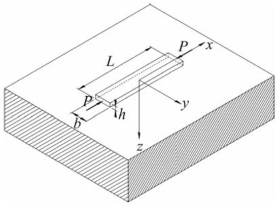
Figure 2.
Compressed beam on elastic support.
Frictionless and bilateral conditions are assumed between the beam and the elastic support. Infinite stiffness along the beam width is also assumed, hence beam behavior does not vary along the direction. This hypothesis allows us to consider beam vertical displacement coincident with that of the support surface. However, this condition generates a vertical reaction enforced on both the beam and substrate, which cannot be constant along the direction in the case of an elastic half-space support [33].
2.1.1. Pavement Support Models
In this work, three different types of support are considered. The first one is the well-known Winkler model [27], which is largely adopted in the literature [26], and it is characterized by a stiffness parameter that linearly correlates the beam vertical displacement and support reaction, varying only along the beam length :
The Winkler support can be considered a set of independent springs with the same stiffness placed above the beam. Such a model can be considered insufficiently accurate for representing a support given by an elastic continuum since a vertical displacement does not generate contact reactions far from its application point. A more realistic model for representing the continuous elastic support of the pavement is given by an elastic three-dimensional half-space. In this case, the Boussinesq solution [34,35] can be adopted:
where and are, respectively, Young’s modulus and Poisson’s ratio of the half-space, and
is the distance between two points and on the contact surface between the beam and half-space. In this case, half-space reactions can vary along both directions of the contact surface, whereas the beam hypothesis considers its rigidity along the direction, hence . In a recent contribution dedicated to the buckling of slender beams and coatings on the elastic half-space, buckling loads turned out to be strictly related to the length-to-width ratio (), and for decreasing such a ratio, a convergence of critical loads to those typical of plane strain conditions was found [31].
For this reason, a third elastic support type is considered, namely the elastic half-plane. This support type requires considering plane stress or plane strain conditions for the entire system, which are not in full agreement with the case of a pavement modeled as a beam. In this latter case, beam–support vertical displacements are defined in terms of the Boundary Integral Equation known as the Flamant solution [34], which adopts the Green function of the half-plane, representing half-plane surface displacement generated by a unitary point force normal to its boundary:
with or ) for plane stress or plane strain state, respectively.
It is worth noting that the main difference between the Winkler support and 3D or 2D supports is given by the non-local relationships between vertical displacements and contact reactions (Equations (3) and (5)), which are typical of elastic continuous supports. The proposed comparison between the effects of the Winkler support, 3D, and 2D continuum supports was already proposed by Biot [36] for the bending of infinite beams.
Other models suitable for representing pavement support, more realistic than the Winkler one but able to better account for the fast decay of displacements far from loaded regions, are the so-called two-parameter foundation models [37] and models able to account for long-range interactions [38].
2.1.2. Jointed Pavement
One internal hinge or joint is considered at the beam midpoint (Figure 3). The hinge allows relative rotation between the half-beams connected; it can represent, on the one hand, an existing joint due to construction phases of the pavement, or, on the other hand, it can represent an existing crack due to past thermal variations or other damage conditions. Following the procedure already adopted by Baraldi and Tullini [39], the internal hinge is modeled as a semirigid connection with nil rotational stiffness.

Figure 3.
Compressed beam with an internal hinge or joint at midpoint on elastic support.
2.2. Variational Formulation
The total potential energy of the system can be written as the sum of beam potential energy including second-order effects, and support potential energy , as follows:
where prime denotes differentiation with respect to x, and is beam bending stiffness. Vertical displacement, as well as support reactions, can assume one of the expressions listed in Section 2.1 for each proposed support type. It is worth noting that integration along the beam width holds for the half-space support only. The total potential energy of the system turns out to be a mixed functional, with unknowns represented by beam vertical displacements and support reactions. However, the simpler case of the Winkler support can be treated as a standard variational formulation, given that reactions are linearly dependent on vertical displacements. Following the approach already adopted for buckling of beams on half-plane [30] and half-space [31] supports, the constraint equations for representing beam boundary conditions are included in the total potential energy of the system by means of a penalty approach [40].
2.3. Numerical Model
The numerical model is defined by subdividing the beam into equally spaced FEs having length . Then, nodes are defined, and two degrees of freedom for each node, one vertical translation and one rotation, are considered. In the same manner, the beam–support contact surface is subdivided into portions having the same length as the beam ones. For simplicity, this discretization is also adopted for the half-space support case, namely without considering contact surface discretization along the beam width. This aspect was investigated by Baraldi and Tullini both with static [33] and buckling [32] analyses. In the latter case, it was found that the order of magnitude of buckling loads with no discretization along the beam width was still in agreement with results obtained with more accurate graded discretization choices if a sufficiently refined discretization was adopted along beam length, namely .
Following the approach already adopted by Baraldi and Tullini [30,31,33,39], beam FEs are characterized by classical Hermitian polynomials assumed as shape functions [40], whereas constant shape functions are assumed for contact reactions. Then, the total potential energy of the system (Equation (6)) in discrete form can be written as follows:
where the vector contains the beam’s degrees of freedom, the vector contains the contact support reactions, is the vector of external loads, is the stiffness matrix of the beam, is the geometric matrix, and is a matrix collecting dimensionless coefficients representing equivalent nodal actions generated by beam–support contact reactions over the beam. Matrix is the compliance or flexibility matrix of the support and depends on the type of support chosen. Details on matrices appearing in Equation (7) are presented in Appendix A. It is worth mentioning that in the case of the Winkler support, turns out to be a diagonal matrix, whereas half-plane or half-space supports lead to fully populated matrices.
The stationarity condition of the total potential energy written in discrete form allows us to obtain the following system:
which is characterized by the following solution:
where is the stiffness matrix of the support, varying for the support type chosen:
It can be demonstrated that numerical tests adopting in the case of the Winkler support are equal to those adopting the Winkler stiffness matrix that can be obtained with a standard variational formulation [41]. In order to determine pavement buckling loads, a homogeneous system associated with Equation (10) is considered and buckling loads are determined as the roots of the following eigenvalue problem:
where the axial load can be written in dimensionless form as . As is well known, the Euler critical load can be defined as ; hence, the dimensionless buckling loads that are going to be determined in the subsequent Section 3 are the following:
Beam–Support Stiffness Parameters
It is common to describe the results of analytical and numerical static and buckling tests by defining the beam–support stiffness parameters that are able to account for both beam and support stiffness in a unique parameter. In the case of the Winkler support, the beam–support parameter is defined as follows [26]:
Such a parameter was also adopted in a recent work investigating thermal effects on pavement buckling [21]. In the case of elastic supports, both in 2D and 3D cases, the beam-support parameter is defined as [30,31,32,33,36,39,42,43]:
Even if based on different support behavior hypotheses, both beam–support stiffness parameters can be interpreted in the same manner. Namely, small values of such parameters represent short beams, stiffer than the support, whereas large values of such parameters describe long beams on stiff support. It is worth noting that the pioneering contribution by Biot [36] proposed an expression for correlating the Winkler stiffness parameter with half-plane and half-space elastic moduli.
3. Results
In order to simulate the behavior of jointed concrete pavement, avoiding the effect of boundary conditions at beam ends, a compressed beam with fixed ends and a hinge at the midpoint is considered (Figure 4). Restraint conditions applied by means of a penalty approach are and . In this section, buckling analyses are performed by considering the three different support types described in Section 2.1. The first and second critical loads and the corresponding modal shapes, together with contact reactions, are determined for several values of beam–support stiffness parameters. Then, critical load values with increasing beam–support stiffness parameters are determined and their convergence with existing or new results is determined. Analyses are performed by adopting . It is worth noting that the first modal shape is determined as the fundamental one related to pavement blowup, whereas the second modal shape is determined to perform a better interpretation of the results in terms of critical loads.

Figure 4.
Compressed beam with an internal hinge at midpoint and fixed ends, on elastic support.
3.1. Beam on Winkler Support
3.1.1. Modal Shapes
Figure 5 shows modal shapes obtained with four increasing values of , highlighting the corresponding increasing dimensionless critical loads. Contact reactions are not presented for simplicity, given that they are proportional to displacements (Equation (2)). Modal shapes related to the first critical load (Figure 5a,c,e,g) are symmetric and characterized by maximum values at the weak section or joint at the midpoint, with an evident slope inversion due to the presence of the internal hinge. Modal shapes related to the second critical load (Figure 5b,d,f,h) are sinusoidal and asymmetric, hence the asymmetric rotation at the midpoint is not influenced by the presence of the internal hinge.
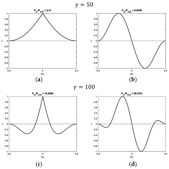
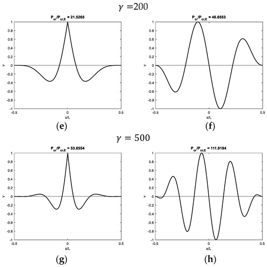
Figure 5.
Buckling of a beam with fixed ends and a hinge at midpoint on Winkler support for several increasing values of : (a,c,e,g) first modal shapes and (b,d,f,h) second modal shapes.
3.1.2. Critical Loads
Following behavior that can be determined analytically and numerically for beams without weak joints [26], critical loads increase with increasing (Figure 6a). The first critical load appears to be an independent curve, not intersecting the other ones, whereas curves related to subsequent critical loads intersect each other. In order to have an analytical estimation of the critical loads as a function of , as is well known [26], critical loads for beams on the Winkler support are proportional to . The determination of minimum critical loads with respect to leads to results linearly proportional to . Then, dimensionless critical loads are divided by in Figure 6b, obtaining the first curve converging to (dashed line)
which is exactly equal to one-half of the convergence value of the second critical load with increasing (dashed-dotted line): . Such a value is typical of beams with fixed or sliding ends without weak joints.
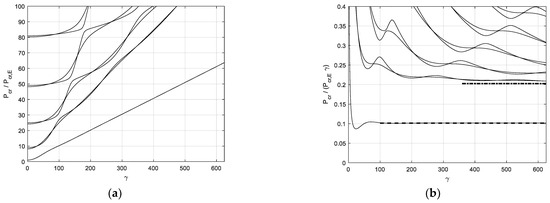
Figure 6.
Critical loads for a beam with fixed ends and a hinge at midpoint on Winkler support: (a) dimensionless critical loads versus beam–support stiffness parameter and (b) ratio versus beam–support stiffness parameter.
3.2. Beam on Half-Space
Numerical tests are performed for a beam length-to-width ratio .
3.2.1. Modal Shapes
Figure 7, Figure 8, Figure 9 and Figure 10 show modal shapes and contact reactions obtained with four increasing values of , highlighting the corresponding increasing dimensionless critical loads. Modal shapes related to the first critical load (Figure 7a, Figure 8a, Figure 9a and Figure 10a) are symmetric and characterized by maximum values at the weak section or joint at the midpoint, with an evident slope inversion due to the presence of the internal hinge. Modal shapes related to the second critical load (Figure 7b, Figure 8b, Figure 9b and Figure 10b) are sinusoidal and asymmetric. Contact reactions (Figure 7c,d, Figure 8c,d, Figure 9c,d and Figure 10c,d) are not fully proportional to the corresponding vertical displacements along the beam length and can assume nonzero values close to the beam ends even if displacements are nil in the case of soft supports (Figure 7c,d, Figure 8d, Figure 9d and Figure 10d).
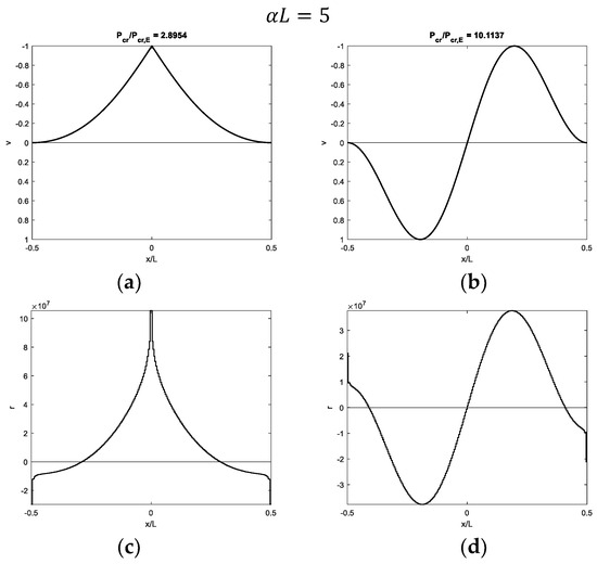
Figure 7.
Buckling of a beam with fixed ends and a hinge at midpoint on 3D half-space with = 5: (a,b) first and second modal shapes and (c,d) corresponding contact reactions.
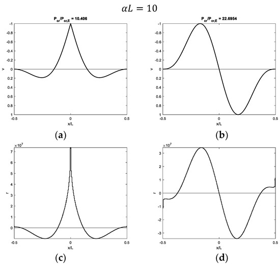
Figure 8.
Buckling of a beam with fixed ends and a hinge at midpoint on half-space with : (a,b) first and second modal shapes and (c,d) corresponding contact reactions.
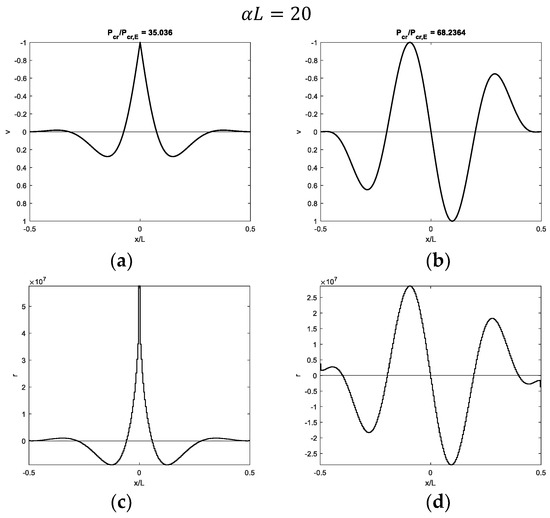
Figure 9.
Buckling of a beam with fixed ends and a hinge at midpoint on half-space with : (a,b) first and second modal shapes and (c,d) corresponding contact reactions.
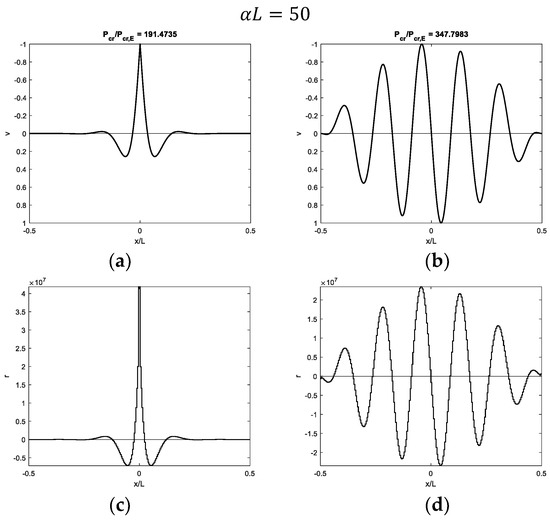
Figure 10.
Buckling of a beam with fixed ends and a hinge at midpoint on half-space with : (a,b) first and second modal shapes and (c,d) corresponding contact reactions.
3.2.2. Critical Loads
Figure 11a shows increasing dimensionless critical loads versus . The first critical load appears to be an independent curve, not intersecting with the other ones, whereas the curves related to subsequent critical loads intersect with each other. In a previous contribution by the author [32] and in the case of infinite beams on elastic supports, critical loads turned out to be proportional to with increasing . Consequently, minimum critical loads turned out to be proportional to . In order to have an estimation of the critical loads as a function of , dimensionless critical loads are divided by in Figure 11b, obtaining the first curve converging to (dashed line)
whereas the second and third curves converge to (dashed-dotted line)
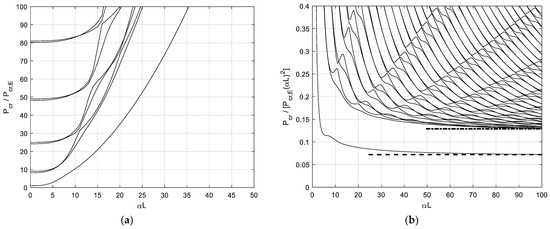
Figure 11.
Buckling of a beam with fixed ends and a hinge at midpoint on half-space. (a) Dimensionless critical loads versus beam–support stiffness parameter; (b) Ratio versus beam–support stiffness parameter.
Both values are different from those obtained for beams without internal hinges [31].
3.3. Beam on Half-Plane
3.3.1. Modal Shapes
Figure 12, Figure 13 and Figure 14 show the first and second modal shapes and corresponding contact reactions obtained with three increasing values of , highlighting the corresponding increasing dimensionless critical loads. The same preliminary comments made in Section 3.2.1 for 3D support can be applied in the case of 2D support.
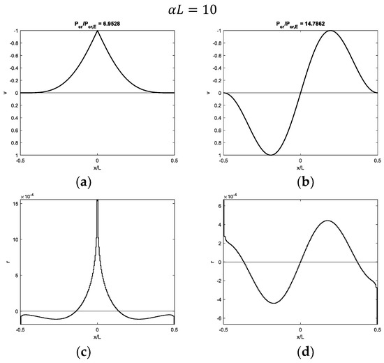
Figure 12.
Buckling of a beam with fixed ends and a hinge at midpoint on half-plane with : (a,b) first and second modal shapes and (c,d) corresponding contact reactions.
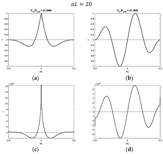
Figure 13.
Buckling of a beam with fixed ends and a hinge at midpoint on half-plane with : (a,b) first and second modal shapes and (c,d) corresponding contact reactions.
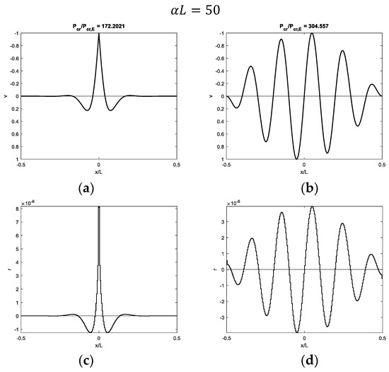
Figure 14.
Buckling of a beam with fixed ends and a hinge at midpoint on half-plane with : (a,b) first and second modal shapes and (c,d) corresponding contact reactions.
3.3.2. Critical Loads
Following the representation already adopted in Figure 11, Figure 15a shows increasing dimensionless critical loads, whereas Figure 15b shows the ratio versus . In this case, the first critical load converges to the following ratio (dashed line):
whereas the second and third curves converge to (dashed-dotted line)

Figure 15.
Buckling of a beam with fixed ends and a hinge at midpoint on half-plane. (a) Dimensionless critical loads versus beam–support stiffness parameter; (b) Ratio versus beam–support stiffness parameter.
Which is the typical critical load of a beam of infinite length on an elastic half-plane [44].
4. Discussion
The results proposed in Section 3 in terms of modal shapes show comparable behavior for the beam, taking into consideration the different support typologies. In particular, the first modal shapes are always characterized by non-sinusoidal profiles, with large displacements close to the joint at the beam midpoint, whereas the second modal shapes are asymmetric and sinusoidal. Critical loads turn out to be strictly dependent on the specific beam–support stiffness parameter adopted, but they generally increase with increasing beam length and support stiffness. The first critical load, corresponding to non-sinusoidal modal shapes, is always represented by an independent curve for increasing beam–support stiffness parameters. This aspect is caused by the hinge at the beam midpoint, which activates a modal shape with large displacement at the hinge position, in the same manner as the first modal shape of a cantilever beam. In this case, the further effect of the beam elastic support does not influence the modal shape type but tends to concentrate nonzero displacements close to the beam midpoint. Curves related to the second and subsequent critical loads, corresponding to sinusoidal modal shapes, always intersect themselves and converge to values typical of beams without internal hinges.
4.1. Beam on Winkler Support
Starting with the simpler case of the beam on the Winkler support, it is worth mentioning that the results obtained in Section 3.1 turn out to be in agreement with those obtained by Wang [28] for the case of an infinite beam with a weak joint. This agreement is obtained in particular with increasing values, namely increasing beam length.
4.1.1. Modal Shapes
The first modal shape obtained in the case of soft support is not sinusoidal and it is characterized by a displacement increasing from zero at the beam ends to the maximum value at the beam midpoint (Figure 5a). Such a modal shape turns out to agree with that generally proposed as an example of concrete pavement blowup in the case of joints at the beam midpoint (Figure 1). Considering the proportional relationship between vertical displacements and contact reactions (Equation (2)), tensile contact reactions between the beam and support are obtained along the whole beam length, except at the beam ends. Then, detachment between the beam and support involves almost the entire beam length.
As the parameter increases, both support stiffness and beam length increase, and displacements tend to be large only close to the midpoint (Figure 5c,e,g), whereas the beam portion with nil values close to the beam ends increases with increasing . Furthermore, a sign of variation in vertical displacements can be detected, since they are initially directed downwards and then upwards from the beam end to the beam midpoint. Along the beam–support surface, this behavior generates tensile reactions close to the beam midpoint and compressive reactions in an intermediate beam portion between the beam midpoint and ends. Then, detachment between the beam and support is limited to a short portion close to the beam midpoint.
It is finally worth noting that all the modal shapes corresponding to the first critical load (Figure 5a,c,e,g) are not sinusoidal. Considering one-half of the beam, these displacement profiles are equal to that typical of beams with free or pinned ends, which are characterized by first (and second) modal shapes having a non-sinusoidal profile, with large displacements close to the beam ends [45].
Focusing then on modal shapes corresponding to the second critical load (Figure 5b,d,f,h), sinusoidal asymmetric modal shapes are obtained, with an increasing number of half-waves as increases. Such modal shapes are typical of beams with fixed or sliding ends without hinge at the midpoint.
4.1.2. Critical Loads
As stated in Section 3.1.2, the first critical load as increases, which is related to non-sinusoidal modal shapes, converges to a typical buckling value for the beam on a Winkler support (Equation (16), Figure 6b), which can be obtained for beams with free ends or pinned ends by setting relative displacements between beam ends equal to zero by means of a penalty function. As already mentioned, such a value is one half of the value that can be obtained in the case of fixed or sliding ends, and it also corresponds to the second critical load of the proposed case study, characterized by asymmetric sinusoidal modal shapes.
4.2. Beam on Elastic Continuum
This section is dedicated to commenting on the results obtained with both 2D and 3D pavement supports, since modal shapes and critical loads with respect to the beam–support stiffness parameter turn out to have similar behavior.
4.2.1. Modal Shapes
Focusing on the modal shapes corresponding to the first critical loads, the vertical displacement profiles are similar to those obtained with the Winkler support, and the same comments can be made as support stiffness and beam length increase. In the case of soft supports, the first modal shape is not sinusoidal, and it is characterized by a displacement increasing from zero at the beam ends to the maximum value at the beam midpoint (Figure 7a and Figure 12a). However, the simple profile, characterized by displacements directed upwards, is obtained with the softer 3D support (Figure 7a) with respect to the 2D support (Figure 12a). As the parameter increases, displacements only tend to increase close to the midpoint (Figure 8a, Figure 9a and Figure 10a for the 3D case and Figure 13a and Figure 14a for the 2D case). Furthermore, a sign of variation in vertical displacements can be detected, since they are initially directed downwards and then upwards from the beam end to the beam midpoint. Comparing the 3D and 2D elastic support cases, the increasing beam portion characterized by nil displacements starting from the beam ends is obtained with smaller values in the 3D support (Figure 8a) relative to the 2D one (Figure 13a). It is worth noting that if only one-half of the beam is considered, non-sinusoidal modal shape profiles turn out to be quite similar to those obtained with beams with free or pinned ends on the same elastic support types. However, several comments are made in the upcoming subsection about the corresponding critical loads. Modal shapes corresponding to the second critical load are sinusoidal with an increasing number of half-waves as the parameter increases.
Focusing on contact reactions, it is worth remembering that the elastic continuum is characterized by a non-local relationship between vertical displacements and reactions (Equations (3) and (5)). This aspect is quite evident when looking at contact reactions related to the first modal shapes close to the beam midpoint, which are distributed over a smaller beam length (Figure 7c, Figure 8c, Figure 9c, Figure 10c, Figure 12c, Figure 13c and Figure 14c) with respect to the beam portion with displacements directed upwards (Figure 7a, Figure 8a, Figure 9a, Figure 10a, Figure 12a, Figure 13a and Figure 14a).
4.2.2. Critical Loads
In contrast to the Winkler support case, the first critical load corresponding to the non-sinusoidal modal shapes turns out to converge to new values (Equations (17) and (19)), which were never found for beams with free or pinned ends on 2D [30] or 3D half-space supports [31]. Furthermore, the second critical load in the case of half-space support converges to a new value (Equation (18)), whereas in the case of half-plane support, the existing solution, obtained by Reissner [44] for beams having infinite length, is obtained.
It is worth mentioning that the buckling behavior of a beam on a half-space support is strictly dependent on its length-to-width ratio . In the case of beams without internal hinges, it is demonstrated that critical loads with respect to the parameter turn out to converge with the buckling behavior of a beam on half-plane as the ratio increases. In order to highlight this aspect in the case of a beam with a hinge at the midpoint, the first and second critical loads are determined for several values. Table 1 collects several ratios determined for the first and second critical loads with and varying . Figure 16 shows the ratio with increasing . The results are compared with those obtained with an elastic half-plane.

Table 1.
Dimensionless critical loads of a beam with fixed ends and a hinge at midpoint on half-space with and varying .
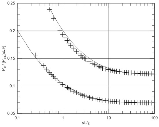
Figure 16.
First (non-sinusoidal modal shapes) and second (sinusoidal modal shapes) critical loads. Ratio versus . Plus symbols represent numerical results; continuous lines represent Equations (21) and (22).
The following expression is proposed for estimating the first critical load:
whereas the expression already proposed in [31] turns out to be suitable for estimating the second (and third) critical load(s):
Both expressions are added in Figure 16 with continuous lines, showing good agreement with numerical results.
4.3. Calculation Examples
The results obtained in Section 3 and discussed in Section 4.1 and Section 4.2 and are further investigated by assuming several values for concrete pavement geometric and elastic parameters, together with elastic support parameters. To have comparable numerical results, the relationship between Winkler support stiffness and half-space elastic moduli proposed by Biot [26] is adopted:
The following Table 2 collects several values of critical loads determined for pavement with varying thicknesses, on two different support types.

Table 2.
Calculated critical loads.
5. Conclusions
In this work, a simple and effective mixed FEM, originally introduced for performing static and buckling analyses of beams on elastic support, has been extended for a preliminary study of jointed concrete pavement blowups caused by buckling in compression caused by thermal rise. An elastic Euler–Bernoulli beam in frictionless and bilateral contact with an elastic support was considered, by adopting three different support models, namely a Winkler support, elastic half-space, and elastic half-plane. A hinge at the beam midpoint was placed to simulate a transversal pavement joint or crack. Numerical tests showed that minimum critical loads are always associated with modal shapes having maximum upward displacements at the beam midpoint with a sudden slope variation due to the presence of the hinge. However, the typical increasing displacement from beam ends to beam midpoint was obtained only in the case of soft supports. This aspect is not completely in agreement with the blowups shown by Kerr, which were determined in the case of full rigid supports. Increasing support stiffness and beam length, vertical displacements, and, consequently, potential detachment from the support turned out to be limited to a beam portion close to the midpoint and characterized by small displacements initially directed downwards and then large displacements directed upwards.
In the case of the Winkler support, the minimum critical load with increasing support stiffness turned out to be equal to that typical of beams with free ends, which is one-half of that obtained with beams having fixed or sliding ends. In the case of the elastic half-space, the ratio between the beam length and width governed numerical results, and as the ratio increased, convergence with the results in the case of the half-plane was observed. Differently from the Winkler support case, with continuous elastic support, the first critical load turned out to converge to a new value, smaller and not depending on existing values obtained with beams with free or pinned ends. On the other hand, the second critical load, related to asymmetric sinusoidal modal shapes, converged to the typical critical load of a beam with fixed or sliding ends, equal to Reissner’s pioneering solution for the buckling of infinite beams on half-plane support [38].
Further developments of this work will first focus on studying a more realistic case study by accounting for the friction between the beam and support and also performing geometric nonlinear incremental analysis in the presence of increasing compression and pavement self-weight. Nonlinear incremental analyses will also allow us to account for unilateral contact, namely an actual uplift, between pavement and support. Other types of concrete pavement blowups [17] will also be taken into consideration. Also, focusing on pavement support models for more practical case studies, it can be pointed out that continuous elastic support does not account for the fast decay of surface displacements far from loaded regions [38]. Further developments of this work will apply the proposed mixed approach to other pavement support models, for instance, the Pasternak one [37] and similar two-parameter foundation models [43].
The use of the Timoshenko beam model represents a further possibility of improvement for the proposed approach. The buckling of continuous Timoshenko beams on elastic supports is a topic already investigated in the literature [32]. However, such a beam model will be accurate for simulating buckling in cases of thick and short pavements.
Funding
This research received no external funding.
Data Availability Statement
Dataset available on request from the author.
Conflicts of Interest
The author declares no conflicts of interest.
Appendix A
For a generic i-th beam element, the stiffness and geometric matrices are
A generic column of matrix is
Compliance matrix is a square matrix having size . In the case of the Winkler support, its elements are
with varying from 1 to .
For simplicity, details on the components of the compliance matrix in the case of an elastic half-space can be found in [25,26] and in [24] for an elastic half plane.
References
- Repair of concrete blowups in Delaware. Eng. News Rec. 1925, 95.
- Woods, K.B.; Sweet, I.-I.S.; Shelburne, T.E. Pavement blowups correlated with source of coarse aggregate. Proc. Highw. Res. Board 1945, 25. [Google Scholar]
- Hveem, F.N. Types and causes of failure in highway pavements. HRB Bull. 1958, 187, 1–52. [Google Scholar]
- Hensley, M.J. The Study of Pavement Blowups; Research Project 10; Arkansas State Highway Department: Little Rock, AR, USA, 1966. [Google Scholar]
- Stott, J.P.; Brook, K.M. Report on a Visit to U.S.A. to Study Blowups in Concrete Roads; Road Research Laboratory Report LR 128; British Ministry of Transport: London, UK, 1968. [Google Scholar]
- Levi, R. Perrin: Les risques de soulevement des pistes et des roies ferrees. Inst. Tech. Bâtim. Trav. Publics Circ. Sér. 1947, 36. [Google Scholar]
- Bergstrom, S.G. Temperature stresses in concrete pavements. In Proc. Swedish Cement and Concrete Research Institute at the Royal Institute of Technology; Stockholm, Sweden, 1950. [Google Scholar]
- Stabilini, L. Über die maximale Länge der monolithischen Beläge für Strassen und Flugplätze. In Stahlbau und Baustatik—Aktuelle Probleme; Grengg, H., Pelikan, W., Reinitzhuber, F., Eds.; Springer: Wien, Vienna; New York, NY, USA, 1965. [Google Scholar]
- Kawaguchi, M. Thermal buckling of continuous pavement. Trans. JSCE 1969, 1, 37–52. [Google Scholar] [CrossRef][Green Version]
- Kawaguchi, M. Thermal buckling of concrete pavements with joints. Trans. JSCE 1972, 4, 13–20. [Google Scholar]
- Kerr, A.D.; Dallis, W.A., Jr. Blowup of Concrete Pavements; Department of Civil Engineering Report, CE-81-20; University of Delaware: Newark, DE, USA, 1981. [Google Scholar]
- Kerr, A.D.; Shade, P.J. Analysis of concrete pavement blowups. Acta Mech. 1984, 52, 201–224. [Google Scholar] [CrossRef]
- Kerr, A.D.; Shade, P.J. Analytic Approach to Concrete Pavement Blowups. Transp. Res. Rec. 1983, 930, 78–83. [Google Scholar]
- Kerr, A.D. The stress and stability analysis of railroad tracks. J. Appl. Mech. 1974, 41, 841–848. [Google Scholar] [CrossRef]
- Kerr, A.D. Analysis of thermal track buckling in the lateral plane. Acta Mech. 1978, 30, 17–50. [Google Scholar] [CrossRef]
- Kerr, A.D. Blowup of a concrete pavement adjoining a rigid structure. Int. J. Non-Linear Mech. 1994, 29, 387–396. [Google Scholar]
- Kerr, A.D. Assessment of Concrete Pavement Blowups. J. Transp. Eng. 1997, 123, 123–131. [Google Scholar]
- Croll, J.G.A. Thermal buckling of pavement slabs. Proc. Inst. Civ. Eng. Transp. 2005, 158, 115–126. [Google Scholar]
- Hernandez, J.A.; Al-Qadi, I. Concrete Pavement Blowup Considering Generalized Boundary Conditions. J. Transp. Eng. Part B Pavements 2018, 144, 04018038. [Google Scholar]
- Mahfuda, A.; Siswosukarto, S.; Suhendro, B. The Influence of Temperature Variations on Rigid Pavement Concrete Slabs. J. Civ. Eng. Forum 2023, 9, 139–150. [Google Scholar] [CrossRef]
- Li, M.; Dai, Q.; Su, P.; You, Z. Buckling prediction based on joint opening and safe temperature estimation in jointed plain concrete pavements. Constr. Build. Mater. 2024, 444, 137630. [Google Scholar]
- Yang, G.; Bradford, M.A. A refined modelling for thermal-induce upheaval buckling of continuously reinforced concrete pavements. Eng. Struct. 2017, 150, 256–270. [Google Scholar]
- Yang, G.; Bradford, M.A. Thermal-induced upheaval buckling of concrete pavements incorporating the effects of temperature gradient. Eng. Struct. 2018, 164, 316–324. [Google Scholar]
- Ahn, H.R.; Kim, Y.K.; Alalade, S.; Lee, S.W. Prediction of blow-up for jointed concrete pavement. Int. J. Pavement Eng. 2025, 26, 2470859. [Google Scholar] [CrossRef]
- Lee, S.W.; Ahn, H.R.; Alalade, S.; Ryu, S.W.; Xu, Y.; Wright, M. Pavement growth and blow-up analysis model for jointed concrete pavement. Constr. Build. Mater. 2025, 469, 141025. [Google Scholar]
- Heteny, M. Beams on Elastic Foundation: Theory with Applications in the Fields of Civil and Mechanical Engineering; University of Michigan Press: Ann Arbor, MI, USA, 1946. [Google Scholar]
- Wang, C.Y. Optimum Location of an Internal Hinge of a Uniform Column on an Elastic Foundation. J. Appl. Mech. 2008, 75, 034501. [Google Scholar]
- Wang, C.Y. Buckling of a weakened infinite beam on an Elastic Foundation. J. Eng. Mech. 2010, 136, 534–537. [Google Scholar]
- Winkler, E. Die Lehre von der Elastiztat und Festigkeit; Dominicus: Prague, Czech Republic, 1867. [Google Scholar]
- Tullini, N.; Tralli, A.; Baraldi, D. Stability of slender beams and planes resting on 2D elastic half-space. Arch. Appl. Mech. 2013, 83, 467–482. [Google Scholar]
- Baraldi, D.; Tullini, N. Buckling of beams and coatings of finite width in bilateral frictionless contact with an elastic half space. Int. J. Solids Struct. 2021, 228, 111104. [Google Scholar]
- Baraldi, D. Nonlinear Analysis of Structures on Elastic Half-Space by a FE-BIE Approach. Ph.D. Dissertation, Università degli Studi di Ferrara, Ferrara, Italy, 2013. [Google Scholar]
- Baraldi, D.; Tullini, N. In-plane bending of Timoshenko beams in bilateral frictionless contact with an elastic half-space using a coupled FE-BIE model. Eng. Anal. Bound. Elem. 2018, 97, 114–130. [Google Scholar]
- Johnson, K.L. Contact Mechanics; Cambridge University Press: Cambridge, UK, 1985. [Google Scholar]
- Kachanov, M.L.; Shafiro, B.; Tsukrov, I. Handbook of Elasticity Solutions; Springer Science+Business Media: Dordrecht, The Netherlands, 2003. [Google Scholar]
- Biot, M.A. Bending of an infinite beam on an elastic foundation. J. Appl. Mech. 1937, 4, A1–A7. [Google Scholar]
- Pasternak, P.L. On a New Method of Analysis of an Elastic Foundation by Means of Two Foundation Constants. In Gosuderevstvennoe Izdatlesvo Literaturi po Stroitelstvu i Arkihitekture; USSR: Moscow, Russia, 1954. [Google Scholar]
- Di Paola, M.; Marino, F.; Zingales, M. A generalized model of elastic foundation based on long-range interactions: Integral and fractional model. Int. J. Solids Struct. 2009, 46, 3124–3137. [Google Scholar]
- Baraldi, D.; Tullini, N. Incremental analysis of elastoplastic beams and frames resting on an elastic half-plane. J. Eng. Mech. 2017, 143, 04017101. [Google Scholar]
- Reddy, J.N. An Introduction to the Finite Element Method, 3rd ed.; McGraw Hill: Singapore, 2006. [Google Scholar]
- Yankelevsky, D.Z.; Eisenberger, M. Analysis of a beam column on elastic foundation. Comput. Struct. 1986, 23, 351–356. [Google Scholar]
- Vesic, A.B. Bending of beams resting on isotropic elastic solid. J. Eng. Mech. 1961, 87, 35–53. [Google Scholar]
- Selvadurai, A.P.S. Elastic Analysis of Soil-Foundation Interaction; Elsevier: Amsterdam, The Netherlands, 1979. [Google Scholar]
- Reissner, M.E. On the theory of beams resting on a yielding foundation. Proc. Natl. Acad. Sci. USA 1937, 23, 328–333. [Google Scholar] [PubMed]
- Goodier, J.N.; Hsu, C.S. Nonsinusoidal buckling modes of sandwich plates. J. Aeronaut. Sci. 1954, 21, 525–532. [Google Scholar]
Disclaimer/Publisher’s Note: The statements, opinions and data contained in all publications are solely those of the individual author(s) and contributor(s) and not of MDPI and/or the editor(s). MDPI and/or the editor(s) disclaim responsibility for any injury to people or property resulting from any ideas, methods, instructions or products referred to in the content. |
© 2025 by the author. Licensee MDPI, Basel, Switzerland. This article is an open access article distributed under the terms and conditions of the Creative Commons Attribution (CC BY) license (https://creativecommons.org/licenses/by/4.0/).