Abstract
In the presented work, the main challenge of small hydropower plants—converting low river flow velocities into high generator rotations—is investigated. It was established that applying the flow acceleration effect during interaction with surfaces makes it possible to increase the power output of a small hydropower plant by up to 25%, which corresponds to the level of an innovative solution. Stationary flow amplifiers and their influence on the dynamic interaction of blades were studied. It was revealed that the use of the amplification effect in paired configurations contributes to achieving a multiplicative effect. The potential of small hydropower plants was analytically evaluated, taking into account their dimensions and gear systems. The study was carried out using the method of computational fluid dynamics (CFD), which enables the modeling of complex hydrodynamic processes. Based on the developed three-dimensional model of the object and its discretization into a computational mesh, boundary conditions were set, and the finite volume method was applied to solve the Navier–Stokes equations. To account for turbulent flows, the k-epsilon turbulence model was employed.
1. Introduction
Modern energy needs of mankind continue to grow due to population growth and technological development. In this regard, special attention is paid to environmentally friendly and renewable energy sources, such as hydropower plants. Mini-hydropower plants (mini-HPPs) are one of the most promising types of small renewable energy sources. These installations provide electricity generation by using the potential of small watercourses and, at the same time, have a number of advantages that make them especially attractive for remote and hard-to-reach areas [1,2,3,4,5,6].
First of all, mini-HPPs are highly environmentally friendly. Unlike large hydropower plants, they do not require large-scale construction of dams, flooding of large areas, and changes in natural ecosystems. This allows us to significantly reduce the negative impact on the environment. Moreover, the use of mini-HPPs helps to reduce greenhouse gas emissions, since fossil fuels are not burned in the process of generating electricity [7,8,9].
From an economic point of view, mini-HPPs also have many advantages. They require lower capital costs compared to large hydropower plants or thermal power plants. Their construction and maintenance can be carried out by local enterprises, which stimulates the development of the local economy and creates new jobs. In addition, the payback period for such installations is relatively short, especially in the presence of government support and incentive programs in the field of renewable energy [10,11].
One of the key advantages of mini-HPPs is their autonomy and the ability to integrate into decentralized energy systems. This makes them an ideal solution for energy supply in rural and mountainous regions where there is no centralized power supply. By providing the local population with stable electricity, mini-HPPs contribute to improving the quality of life, developing social infrastructure, and increasing the investment attractiveness of such territories [12,13].
Mini-HPPs are therefore an important element in the strategy of transition to renewable energy sources and reduction of anthropogenic impact on the environment. They contribute to achieving sustainable development goals such as providing affordable and clean energy, combating climate change, and promoting local economic growth.
However, the main challenge of small damless hydropower plants is the low velocity of river flow, which complicates efficient energy production. The slow current must be converted into a high-speed generator mode to ensure optimal electricity generation. The scientific task lies in applying the effect of water flow acceleration through its interaction with hydrosystem elements or additional devices. It is essential that the blades interacting with the flow come into contact with it only during the energy extraction phase. Blades located downstream of the energy-extracting blades cause turbine deceleration. Addressing these issues can significantly increase efficiency and enhance the attractiveness of such systems for consumers.
Increasing attention is being drawn to non-conventional turbine types and mini-hydropower plant (mini-HPP) designs that offer a rethinking of how to interact with water flow. For example, turbines with variable submersion depths or pendulum-based systems allow for a significant reduction in average hydraulic resistance, thereby improving overall efficiency [14,15,16,17]. These approaches are particularly promising in small and medium rivers with fluctuating or limited discharge rates.
Our research on the efficiency of small hydropower plants has examined all the most promising types of turbines, including radial turbines, a proposed non-standard pendulum-type hydropower plant, and a system based on Lenyov’s design [14,15,16]. Based on the analysis of the results, we concluded the following:
- For small hydropower plants operating in rivers with low flow velocities, the maximum efficiency (η) is achieved at the maximum torque on the blades;
- Torque is proportional to the product of the blade’s contact area with the flow and the lever arm length; increasing one or both parameters leads to higher efficiency;
- It is critically important that the blade interacts with the water only during the energy extraction phase and does not create a negative torque when returning to the extraction position, as occurs with the Darrieus turbine;
- This is the fundamental design principle for small hydropower plants intended for low-flow conditions.
Further improvement of mini-hydropower plants can be achieved by accelerating flow streams generated by the deflection (shrouding) of surfaces.
The application of the current amplification principle to mini-hydropower systems can significantly enhance their efficiency and output. Devices utilizing flow constriction (Venturi effect) allow the flow to be concentrated and accelerated in the turbine’s active zone, thereby increasing the specific power of the installation. However, even with theoretically efficient solutions, it is crucial to recognize that each site requires an individual approach [18,19,20].
For this study, an inclined-blade hydropower plant was selected as the most promising option for modification. An important characteristic of this design is the ability of the blades to interact with the flow only during the energy extraction process. In addition, we analyzed the influence of the flow acceleration effect on turbine efficiency and carried out a modification of the turbine geometry to achieve maximum compactness without reducing power output. The results demonstrated a 25% increase in the plant’s efficiency.
The objective of this study is to determine the impact of the flow acceleration effect during interaction with surfaces on the efficiency of mini-hydropower plants (mini-HPPs), as well as to assess the influence of current amplifiers on their overall performance.
2. Materials and Methods
In this study, computational fluid dynamics (CFD), a method known for its ability to accurately model complex hydrodynamic processes [21,22], was used to design the system. To account for turbulent flows, the k-epsilon turbulence model was used, which is one of the most common and effective for calculating turbulent flows.
The modeling was carried out using SolidWorks Flow Simulation 2020 with a three-dimensional computational domain and a detailed mesh (Figure 1). First, a three-dimensional model of the object of study was developed, taking into account all the main structural elements and geometric features of the system. Then, the model was discretized onto a grid adapted for CFD calculations, with an optimal density of elements in areas where intense turbulent flows were expected.
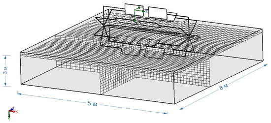
Figure 1.
Three-dimensional computational domain and model discretization in SolidWorks Flow Simulation 2020.
Boundary conditions:
- Domain size: 5 × 5 × 8 m;
- Variable design parameters:
- Blade area: from 0.5 m2 to 3.0 m2;
- Lever length: 1–4 m;
- River velocity: 0.5–2 m/s;
- Distance between current amplifiers: 0.01–0.3 m;
- Mesh size: 30 × 30 mm, with refinement down to 0.2 mm in zones where the spacing between current amplifiers is 10 mm;
- Side walls and bottom—stationary solid boundary condition (no-slip);
- Free surface—free-slip condition;
- Outlet—free outflow condition;
- Calculation mode—steady-state.
To solve the Navier–Stokes equations, the finite volume method was used, which has proven its effectiveness in such problems [23].
The k-epsilon model has been used to calculate viscosity mechanics and simulate turbulent flows. This model takes into account two main variables: the kinetic energy of turbulence (k) and the rate of energy dissipation (epsilon).
Calculations were carried out according to the following dependencies:
1. Conversion of input revolutions into angular velocity (rad/s) using Equation (1):
where rpmin is the input revolutions per minute.
2. Calculation of the input power using Equation (2):
where τin is the input torque, ωin is the angular velocity.
3. Calculation of the output torque using Equation (3):
where gear_ratio is the gear ratio.
4. Calculation of the output angular velocity using Equation (4):
where gear_ratio is the gear ratio.
5. Calculation of the output power using Equation (5):
where τout is the output torque, ωout is the angular velocity.
The geometry of the hydropower plant is shown in Figure 2. The length of the lever is 1–3 m. The blade size is 0.5–2 m2. The river speed is 1 m/s.
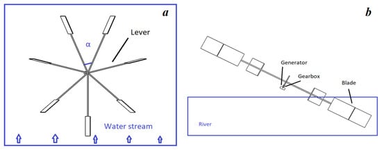
Figure 2.
General view of the rowing mini-hydropower plant: (a) top view; (b) side view.
3. Results and Discussion
It directly follows from Equations (1)–(5) that the output power is equal to the product of the input angular velocity and the input torque and does not depend on the gear ratio.
To analyze the efficiency of a mini-HPP, it is important to consider the dependence of the output power on the input torque at different rotor speeds (rpm). Figure 3 shows the simulation results, which allow us to estimate how changing the number of revolutions affects the generated power of the system.
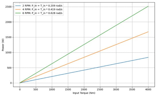
Figure 3.
Dependence of output power on input torque at fixed rotor angular velocities.
For a fixed input torque, the level of generated power increases with the rise in rotor speed. This is reflected in the steeper slope of the lines on the graph. The input power is proportional to the angular velocity. The most efficient operation of the mini-HPP is observed at higher rotor speeds, as this enables maximum conversion of the input torque into power. The graph highlights the importance of rotor rotational speed for achieving the highest efficiency of power generation in mini-hydropower plants.
Figure 4 shows the dependence of torque and angular velocity on lever length. The graph makes it possible to analyze how these parameters change with an increase in lever length, as well as to identify their intersection point.
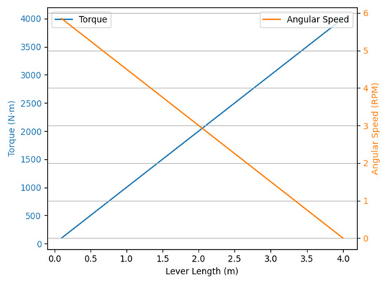
Figure 4.
Dependence of torque and angular velocity on the length of the lever.
The graph illustrates how changes in lever length affect the output torque and the angular velocity of the drive. As the lever length increases, the generated torque rises, while the angular velocity decreases, reflecting the principle of energy conservation and mechanical equilibrium. The curves intersect at a point where the balance between force and speed is achieved—this represents the optimal lever length for specific operating conditions.
Figure 3 and Figure 4 demonstrate the interrelation between the mechanical parameters of the system and allow its performance to be evaluated from two perspectives: through changes in speed at constant torque and through geometric influences on torque and angular velocity.
In the first case, the linear dependence of power on rotational speed at constant torque is confirmed, which is important for assessing the maximum performance capacity.
In the second case, it is shown that changes in lever length lead to a redistribution between torque and speed, forming an optimal balance point for the given conditions.
A combined analysis indicates that the choice of operating mode or design must take into account both force and kinematic factors to achieve maximum system efficiency.
The conducted calculations made it possible to determine the key mechanical dependencies and to reveal the distribution characteristics of torque and speed under various geometric parameters. Based on these data, the values of power losses and the features of energy redistribution within the system were identified.
The next stage of the study is focused on numerical modeling of the hydrodynamics of the installation. The transition to this stage is justified by the fact that, having obtained quantitative estimates of losses and an understanding of mechanical constraints, it is now possible to more accurately analyze the interaction of the flow with structural elements. This will make it possible to
- Investigate the distribution of velocities and low-energy zones;
- Evaluate the influence of blade geometry on flow formation;
- Determine the optimal parameters for the arrangement of elements to minimize hydrodynamic losses.
Figure 5 shows the velocity field that occurs when the flow and blade interact. The figure shows the velocity distribution in a section at a certain height (Section 1). The color scale on the right shows the velocity values in the range from 0 to 1.132 m/s, where the dark blue areas correspond to the minimum velocities, and the red areas to the maximum.
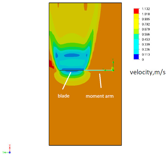
Figure 5.
Velocity field during interaction of flow and blade.
From the figure, it can be concluded that a zone of about 3 m in length is formed behind the blade, in which the flow velocity is significantly reduced. Such a zone is characterized by a low level of kinetic energy of the flow, which makes it unsuitable for efficient energy extraction. This effect can be associated with the formation of a flow shadowing region, where the impact on the flow causes a significant decrease in speed, as well as the potential formation of a vortex zone or turbulence.
In addition, this zone of activity highlights the importance of proper spacing between adjacent blades in multi-blade systems such as turbines or propellers. If adjacent elements of the system are too close to each other, this can lead to a decrease in the overall efficiency of the plant due to the presence of such a zone of “lost” energy.
Thus, understanding the characteristics of this zone can be useful in designing blades to improve their aerodynamic efficiency, as well as to minimize energy losses in the system, which is of great importance for improving the overall performance of the plant.
Figure 6 shows the distribution of turbulence scale in the water flow interacting with the blade. The picture is constructed for Section 1, displaying the features of turbulent motion near the analyzed area. The scale on the left indicates the values of the turbulence scale in the range from 0 to 0.041 m. Blue areas characterize the minimum level of turbulence, while red areas demonstrate maximum values.
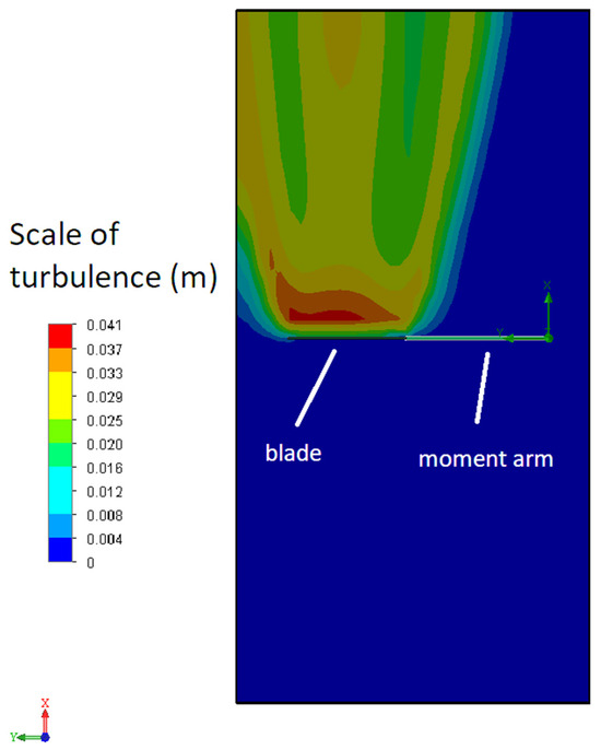
Figure 6.
Turbulence scale during interaction between water flow and blade.
This image allows visualization of the intensity of turbulent phenomena in the interaction zone, which is important for understanding hydrodynamic processes and optimizing the blade design. It is clear that significant turbulence zones arise behind the blade, which can negatively affect the energy intake from the water by the other blade.
Figure 7 shows the dependence of torque on time.
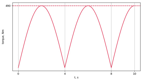
Figure 7.
Dependence of torque on time.
The curve has a periodic oscillatory nature, reaching peak values of about 490 N·m, which is indicated by the horizontal dotted line. The amplitude of the oscillations periodically decreases and returns to zero, indicating the variable nature of the load on the system.
The blades of the mini-HPP demonstrate stable interaction with the water flow, which is reflected in the periodicity of torque oscillations. Maximum torque values of up to 490 N·m indicate that the system can effectively use the flow to generate power.
The periodic decrease in torque amplitude to zero indicates the possibility of improving the flow distribution and blade loading. This provides potential for further research and optimization of the mini-HPP design to improve its efficiency and performance.
Figure 8 shows the dependence of torque on time when installing two blades offset relative to each other by an angle of α/2.
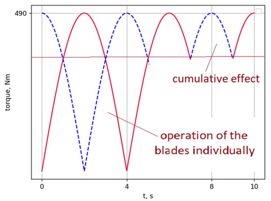
Figure 8.
Torque versus time when installing two blades offset relative to each other by α/2.
It is evident that the resulting moment is smoothed out compared to the individual characteristics. The total curve (red) has a smaller amplitude compared to the individual blades, which indicates the phase alignment of their operation due to the offset. This solution can help to reduce vibrations and increase the stability of the mechanical system.
Next, we installed the current amplifier in the most obvious version at 45 degrees in front of the turbine (Figure 9).
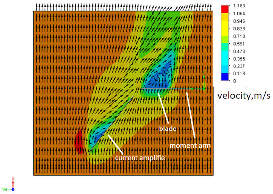
Figure 9.
Current amplifier installed at a 45-degree angle in front of the turbine.
A 3D model illustrating the position of the blade, the current amplifier, the generator with a reducer, and the moment arm within the installation is shown in Figure 10.
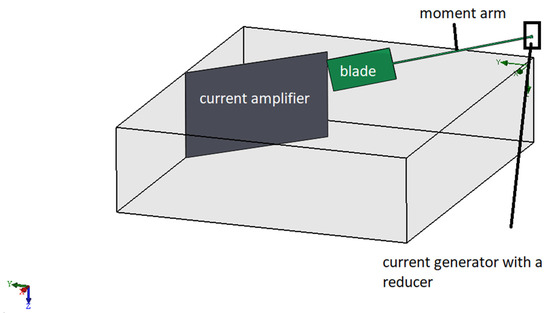
Figure 10.
A schematic 3D representation of the arrangement of the blade, current amplifier, and generator to illustrate the spatial relationship of the elements.
At the same time, the torque on the turbine decreased from 472 N·m to 310 N·m. In this case, the current amplifier became a slowing element. From Figure 9, it is clear that the flow rate decreased, which led to a decrease in torque.
Figure 11 shows the results of the study of the effect of turbulence on turbine torque.
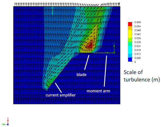
Figure 11.
Effect of turbulence on turbine torque when the current amplifier is installed at 45 degrees.
From Figure 11 it is clear that the amplifier does not change the flow from laminar to turbulent and this cannot be the reason for the decrease in torque.
The current amplifier was also installed at 15 degrees to the turbine (Figure 12).
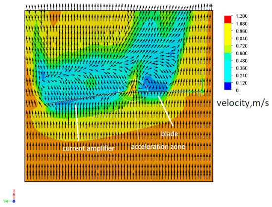
Figure 12.
Current amplifier installed at 15 degrees in front of the turbine.
The torque on the turbine remained almost at the same level (479 N·m), which indicates that the current amplifier does not have a significant effect on the torque. As can be seen from Figure 12, the flow decreases its speed, and the flow direction remains stable. This confirms that installing the amplifier at this angle does not have a significant effect on the overall energy efficiency of the system.
Next, we study the effect of installing the amplifier at 90 degrees (Figure 13).
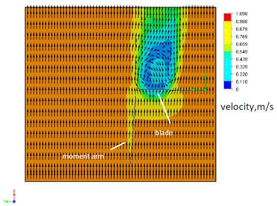
Figure 13.
Current amplifier installed at 90 degrees in front of the turbine.
The torque on the turbine remained at the level of 490 N·m, which indicates the absence of the effect of the current amplifier on the torque. As can be seen from Figure 13, the distribution of flow velocities has remained virtually unchanged, which confirms the invariance of the hydrodynamic characteristics in the turbine operating zone with the amplifier installed.
Figure 14 shows a biased current amplifier.
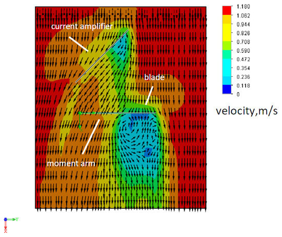
Figure 14.
Current amplifier with bias.
The current amplifier with offset also did not give a significant result either in increasing or decreasing torque (480 N·m).
In addition, we investigated variants with a direct amplifier in the form of a wing only. Narrowing the gap between the current amplifier and the blade gave a 10% increase in torque, which is a good result (Figure 15).
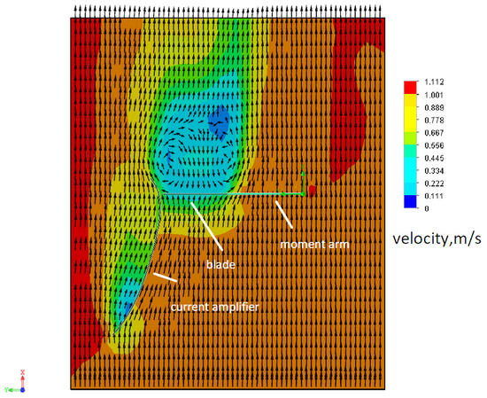
Figure 15.
Narrowing of the gap between the current amplifier and the blade.
By reducing the gap between the current amplifier and the blade using both a straight amplifier and a wing-shaped amplifier, a 10 percent increase in torque (525 N·m) was achieved. Changing the position of the current amplifier relative to the blades has a noticeable effect on turbine performance.
Thus, current amplifiers are able to increase the turbine torque only by reducing the distance between the turbine and the current amplifier. Any changes in the position or geometry of the current amplifier lead to either deterioration or maintenance of the same torque values.
The torque with the concave current amplifier was 490 N·m (Figure 16). Thus, we see that changing the geometry of the current amplifier does not lead to any changes in the torque.
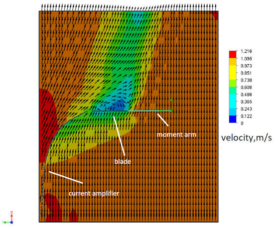
Figure 16.
Geometry with a concave current amplifier.
Figure 17 shows the dependence of torque on the turbine blade area.
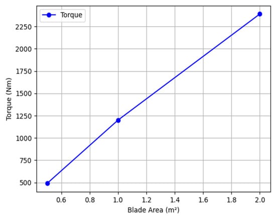
Figure 17.
Graph of torque dependence on blade area.
The graph shows that the torque increases linearly with blade area. As the blade area increases from 0.5 m2 to 2.0 m2, the torque increases from approximately 490 N·m to 2390 N·m. This linear relationship indicates a proportional relationship between the two parameters, meaning that increasing blade area results in a proportional increase in torque. This graph is an important tool for understanding how blade geometry affects the torque generated and can be useful for optimizing blade design to achieve desired performance.
Figure 18 shows the dependence of torque on the length of the lever.
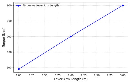
Figure 18.
Torque versus lever length.
The graph shows that the torque increases as the lever length increases. This relationship is also linear, indicating a direct proportional relationship between the lever length and the torque generated. With a lever length of 1 m, the torque is 490 N·m. For a lever length of 2 m, the torque increases to 700 N·m. With a lever length of 3 m, the torque reaches 900 N·m.
Thus, we see that a torque of 4000 N·m and a power of about 2 kW are achievable with a total blade area of 2 m2 and a lever length of 3–4 m. The installation of two or three plants is quite sufficient to supply a small farm.
However, the bulky overall design of conventional hydropower plants limits their applicability in confined spaces and increases material consumption. Moreover, efficiency is reduced due to the high structural mass. In contrast, the newly proposed layout of the inclined-vertical hydropower plant significantly improves the system’s compactness.
The results obtained using current amplifiers and a 10% increase in efficiency suggest that further enhancement of overall efficiency is possible by employing paired blade configurations, which facilitate additional flow acceleration (Figure 19).
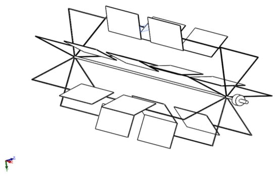
Figure 19.
General view of the modernized hydropower plant.
Simulation of the operation of the new hydropower plant geometry in coaxial and paired configurations and determination of the velocity field are shown in Figure 20.
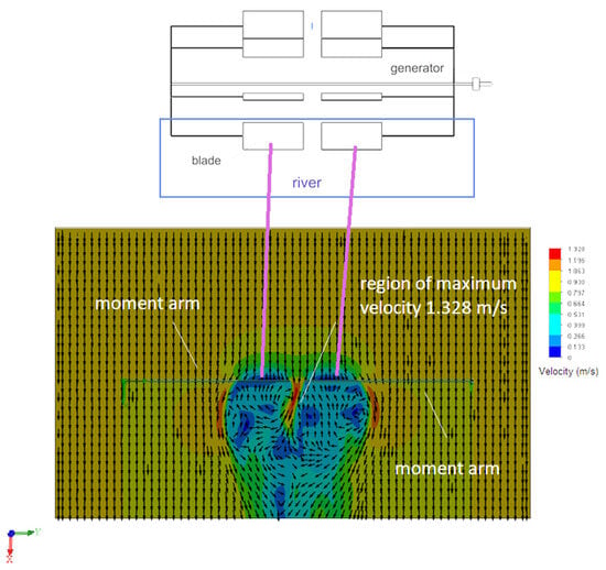
Figure 20.
Velocity field of the flow during interaction between two blades under synchronous rotation (pink line depicts the location of two blades).
Figure 20 shows that when two blades interact, three zones with increased water flow velocity are formed: the maximum velocity reaches 1.3 m/s between the blades and 1.1 m/s along their edges, which corresponds to the level of an innovative solution. This indicator reflects the current state-of-the-art level. Thus, in paired operation of the generator turbines, the acceleration effect is transferred to both turbines by 12%. Such a geometric modification also leads to a reduction in the overall mass of the hydropower plant structure, which in turn contributes to an increase in efficiency.
Let us now consider all the variable factors influencing the torque on a single graph and perform a comparative analysis (Figure 21).
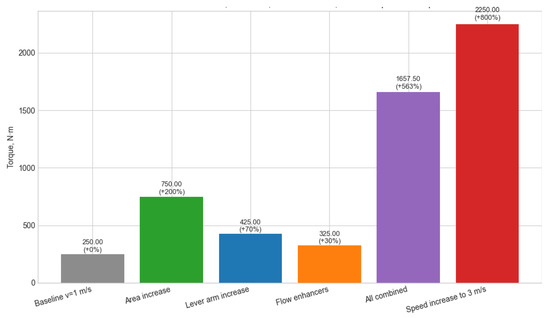
Figure 21.
Relative contribution of key factors to torque in mini-HPP system.
Among the geometric and coefficient variations, the greatest individual contribution comes from increasing the blade area, since torque scales linearly with this parameter. Changes in flow velocity dominate over other factors due to the quadratic dependence on v. Simultaneous variation of parameters leads to a multiplicative effect rather than a simple sum, which highlights the importance of systemic optimization. To maximize torque under otherwise equal conditions, increasing flow velocity is the most effective approach; however, as this is not a controllable variable, geometric modifications and efficiency improvements through current amplifiers also make a substantial contribution and may be preferable when considering energy and structural constraints.
4. Conclusions
The following key findings were achieved during the study:
- It has been established that the low flow velocity of rivers, which limits the application of small-scale hydropower plants, can be overcome by the strategic placement of flow acceleration zones. This approach allows for more efficient spatial utilization and expands the operational potential of mini-HPPs.
- A single acceleration zone can be effectively utilized by multiple turbines, thereby amplifying the efficiency gains.
- A relationship has been identified between the number of blades and power generation pulsations. By selecting an optimal number of blades, it is possible to stabilize the voltage–current characteristics of the generator. Additionally, properly managed gearbox losses contribute to the overall efficiency of the hydropower system.
- It has also been shown that inclined-blade-type hydropower systems offer high potential for modernization, owing to the efficient use of blades and mechanical levers in their design.
- It has been established that this type of hydroturbine provides up to 10 times greater torque per unit blade area compared to a radial turbine. In a radial turbine, the blade simultaneously acts as a lever, so the force determined by the area is not concentrated at the blade tip. Even an ideal hydrodynamic profile cannot compensate for this. The potential of the examined design is explained by shifting the working area toward the blade tip. In terms of torque, this type is comparable to a pendulum turbine, but it has the advantage of avoiding a cyclic operating character. At the same time, the pendulum turbine has virtually no limitations regarding lever length. Compared to Lenev’s design, this type yields up to five times higher torque, which is due to structural limitations of Lenev’s concept in providing sufficient lever length.
- It has also been established that to achieve the highest efficiency of small hydropower plants operating on rivers with low flow velocity, the torque on the blades must be maximized. The greatest contribution to torque comes from the blade–flow contact area, which is proportionally amplified by lever length. Efficiency is further increased through the use of flow acceleration zones, allowing up to a 22% gain in efficiency. It is critically important that the blade interacts with the water only during the energy extraction phase and does not create negative torque when returning to the extraction position, as is the case with the Darrieus turbine. This is the fundamental principle for designing small hydropower plants in low-flow rivers. Protection of hydropower plants from debris, however, should be addressed by separate modular systems.
Future work should investigate the impact of different spatial symmetries in the placement of current amplifiers to further improve system efficiency. Moreover, it is observed that the high-speed flow between the blades forms a wake, indicating that part of the energy remains unutilized. Therefore, revising blade geometry to fully capture this remaining energy may become an additional factor in increasing the overall efficiency.
Author Contributions
Conceptualization, A.Z.; methodology, A.Z. and I.O.; software, I.O.; validation, M.A.; formal analysis, A.Z.; investigation, A.Z. and I.O.; resources, I.O. and M.A.; data curation, A.Z. and M.A.; writing—original draft preparation, A.Z.; writing—review and editing, M.A.; visualization, I.O.; supervision, M.A.; project administration, A.Z.; funding acquisition, A.Z. All authors have read and agreed to the published version of the manuscript.
Funding
This research was funded by the Science Committee of the Ministry of Science and Higher Education of the Republic of Kazakhstan (grant number: AP19677819).
Data Availability Statement
The data presented in this study are available on request from the corresponding author.
Conflicts of Interest
The authors declare no conflicts of interest.
References
- Sachdev, H.S.; Akella, A.K.; Kumar, N. Analysis and evaluation of small hydropower plants: A bibliographical survey. Renew. Sustain. Energy Rev. 2015, 51, 1013–1022. [Google Scholar] [CrossRef]
- Mishra, S.; Singal, S.K.; Khatod, D.K. Optimal installation of small hydropower plant—A review. Renew. Sustain. Energy Rev. 2011, 15, 3862–3869. [Google Scholar] [CrossRef]
- Ashraf, F.B.; Huuki, H.; Haghighi, A.T.; Juutinen, A.; Romakkaniemi, A.; Marttila, H. Valued peaks: Sustainable water allocation for small hydropower plants in an era of explicit ecological needs. Renew. Energy 2025, 244, 122756. [Google Scholar] [CrossRef]
- Hedger, R.D.; Kenawi, M.S.; Sundt-Hansen, L.E.; Bakken, T.H.; Sandercock, B.K. Evaluating environmental impacts of micro, mini and small hydropower plants in Norway. J. Environ. Manag. 2025, 373, 123521. [Google Scholar] [CrossRef] [PubMed]
- Lin, Z.; Qi, X.; Li, M.; Duan, Y.; Gao, H.; Liu, G.; Khan, S.; Mu, H.; Cai, Q.; Messyasz, B. Differential impacts of small hydropower plants on macroinvertebrate communities upstream and downstream under ecological flow. J. Environ. Manag. 2024, 370, 123070. [Google Scholar] [CrossRef] [PubMed]
- Bayazıt, Y.; Bakış, R.; Koç, C. An investigation of small scale hydropower plants using the geographic information system. Renew. Sustain. Energy Rev. 2017, 67, 289–294. [Google Scholar] [CrossRef]
- Zhang, J.; Luo, C.-Y.; Curtis, Z.; Deng, S.; Wu, Y.; Li, Y. Carbon dioxide emission accounting for small hydropower plants—A case study in southwest China. Renew. Sustain Energy Rev. 2015, 47, 755–761. [Google Scholar] [CrossRef]
- Balat, H. A renewable perspective for sustainable energy development in Turkey: The case of small hydropower plants. Renew. Sustain. Energy Rev. 2007, 11, 2152–2165. [Google Scholar] [CrossRef]
- Kuriqi, A.; Pinheiro, A.N.; Sordo-Ward, A.; Bejarano, M.D.; Garrote, L. Ecological impacts of run-of-river hydropower plants —Current status and future prospects on the brink of energy transition. Renew. Sustain. Energy Rev. 2021, 142, 110833. [Google Scholar] [CrossRef]
- Wang, Z.; Tan, Q.; Wen, X.; Su, H.; Fang, G.; Wang, H. Capacity optimization of retrofitting cascade hydropower plants with pumping stations for renewable energy integration: A case study. Appl. Energy 2025, 377, 124429. [Google Scholar] [CrossRef]
- Li, J.; Tian, G.; Wu, Z.; Jin, Y.; Zhou, T. Unveiling benefits: A framework for analyzing small hydropower refurbishment activities. Renew. Sustain. Energy Rev. 2025, 209, 115117. [Google Scholar] [CrossRef]
- Ma, Y.; Huang, Y.; Wu, G.; Liu, J.; Liu, Y.; Xiang, Y.; Liu, Y.; Tang, Z. Decentralized monthly generation scheduling of cascade hydropower plants in multiple time scale markets. Int. J. Electr. Power Energy Syst. 2022, 135, 107420. [Google Scholar] [CrossRef]
- Azimov, U.; Avezova, N. Sustainable small-scale hydropower solutions in Central Asian countries for local and cross-border energy/water supply. Renew. Sustain. Energy Rev. 2022, 167, 112726. [Google Scholar] [CrossRef]
- Zhilkashinova, A.; Ocheredko, I.; Azamatov, B.; Nurbaev, M.; Dogadkin, D.; Abilev, M. Modeling and comparison of design features of pendulum and radial micro-hydropower plants considering the influence of variable design parameters. Designs 2024, 8, 101. [Google Scholar] [CrossRef]
- Zhilkashinova, A.; Abilev, M.; Ocheredko, I.; Tuyakbayev, B.; Nurbayev, M.; Azamatov, B. Mini-hydropower plant based on Lenyov hydrobelt and volume-sectional hydraulic engine. Processes 2022, 10, 368. [Google Scholar] [CrossRef]
- Zhilkashinova, A.; Abilev, M.; Zhilkashinova, A. Microplasma-sprayed V2O5/C double-layer coating for the parts of mini-hydropower systems. Coatings 2020, 10, 725. [Google Scholar] [CrossRef]
- Zhu, Y.; Dong, Y.; Teng, K.; Xu, Y.; Wang, H.; Zhang, Q. Analysis of the causes of pitting corrosion in the 304 stainless steel gate slot of a hydropower station. Eng. Fail. Anal. 2025, 170, 109268. [Google Scholar] [CrossRef]
- Chaulagain, R.K.; Poudel, L.; Maharjan, S. A review on non-conventional hydropower turbines and their selection for ultra-low-head applications. Heliyon 2023, 9, e17753. [Google Scholar] [CrossRef] [PubMed]
- Liu, D.; Li, C.; Tan, X.; Lu, X.; Malik, O.P. Damping characteristics analysis of hydropower units under full operating conditions and control parameters: Accurate quantitative evaluation based on refined models. Appl. Energy 2021, 292, 116881. [Google Scholar] [CrossRef]
- Chen, J.; Zeng, Q.; Zou, Y.; Li, S.; Zheng, Y.; Liu, D.; Xiao, Z. Intelligent robust control for nonlinear complex hydro-turbine regulation system based on a novel state space equation and dynamic feedback linearization. Energy 2024, 302, 131798. [Google Scholar] [CrossRef]
- Liu, D.; Zhang, J.; Lu, X.; Li, C.; Malik, O.P. Model-free adaptive optimal control for fast and safe start-up of pumped storage hydropower units. J. Energy Storage 2024, 87, 111345. [Google Scholar] [CrossRef]
- Morabito, A.; Vagnoni, E. CFD-based analysis of pumped storage power plants implementing hydraulic short circuit operations. Appl. Energy 2024, 369, 123474. [Google Scholar] [CrossRef]
- Perron, S.; Boivin, S.; Hérard, J.-M. A finite volume method to solve the 3D Navier–Stokes equations on unstructured collocated meshes. Comput. Fluids 2004, 33, 1305–1333. [Google Scholar] [CrossRef]
Disclaimer/Publisher’s Note: The statements, opinions and data contained in all publications are solely those of the individual author(s) and contributor(s) and not of MDPI and/or the editor(s). MDPI and/or the editor(s) disclaim responsibility for any injury to people or property resulting from any ideas, methods, instructions or products referred to in the content. |
© 2025 by the authors. Licensee MDPI, Basel, Switzerland. This article is an open access article distributed under the terms and conditions of the Creative Commons Attribution (CC BY) license (https://creativecommons.org/licenses/by/4.0/).