Abstract
This study introduces an innovative deflection-controlled design method (DCM) for evaluating the bearing capacity of offshore mono-bucket foundations (MBFs) in clay, integrating advanced numerical simulations using FLAC3D with the modified cam clay (MCC) soil model. Departing from conventional ultimate bearing capacity approaches, the proposed method prioritizes serviceability limits by constraining foundation deflections to ensure optimal structural performance and turbine efficiency. A systematic investigation revealed that the MBF performance is predominantly governed by eccentricity ratios and soil–structure interaction, with vertical loads exhibiting a minimal impact in a serviceability limit state. Key findings include the following: (1) the rotation center (RC) stabilizes at approximately 0.8 times the skirt length (L) under loading; (2) thin, deep MBFs (aspect ratio > 1.0) exhibit up to a 30% higher bearing capacity compared to wide, shallow configurations; (3) increasing eccentricity ratios (ε = 0.31–1.54) enhance the moment capacity but reduce the allowable horizontal force by 15–20%; (4) compressive vertical loads (υ = −0.30) slightly reduce the normalized bending moments (ω) by 5–10% at low eccentricities (ε < 0.5). The numerical framework was rigorously validated against centrifuge test data, demonstrating high accuracy (error < 3%) in predicting foundation behavior. By bridging geotechnical mechanics with practical engineering requirements, this study provides a robust and efficient design framework for MBFs, offering significant improvements in reliability and cost-effectiveness for offshore wind turbine applications. The proposed DCM successfully guided the design of an MBF in southeastern China, demonstrating its efficacy for use with homogeneous clay.
1. Introduction
In recent years, offshore wind power has experienced rapid development worldwide, with China playing a leading role. According to the Annual Wind Report 2022 published by GWEC, in 2021 new offshore wind installations reached 21.1 GW, of which China accounted for 80%. Approximately half of these projects utilized bucket-type foundations, such as mono-bucket foundations (MBFs) and Bucket-Based Foundations (BBFs). Figure 1 shows a typical BBF installed in north China, comprising a jacket structure supported by four large suction buckets. MBFs and BBFs have become widely recognized as cost-effective and environmentally friendly alternatives to traditional driven piles for offshore foundations [1,2,3]. Therefore, understanding both the failure mechanisms and bearing capacity of MBFs under realistic conditions is essential for their safe and efficient design.
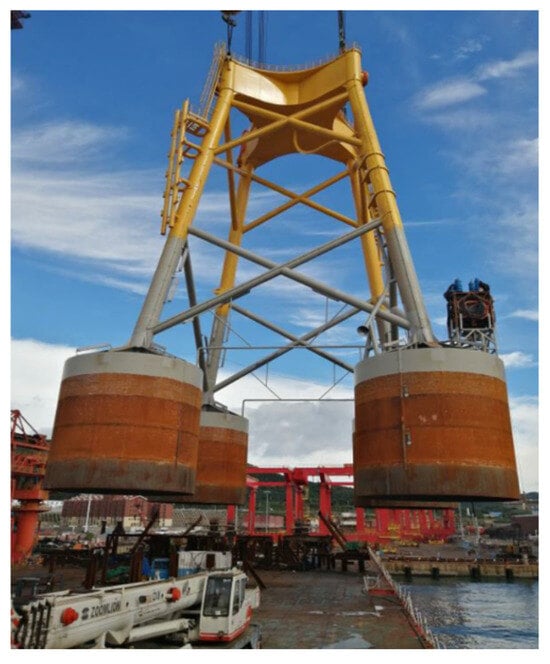
Figure 1.
Bucket-based jacket foundation.
Recent numerical studies have shed light on the complex mechanical behavior of MBFs. Yin (2022) employed a coupled FDM-DEM method to analyze MBF responses at the particle scale, highlighting soil displacement, rotation, force chains, and fabric anisotropy within failure zones [4]. His findings indicate that failure zones in drained sand mainly develop in two areas: beside and beneath the caisson foundation. The loading ratio between the bending moment and horizontal force influences the force chain strength, affecting the bearing capacity distribution. Similarly, Wang and Yin (2020) performed DEM simulations to elucidate the micro-mechanical mechanisms during the installation, operation, and progressive failure of caisson foundations [5]. They observed characteristic stress redistributions in passive and active soil regions during failure progression. Gerolymos et al. (2015) investigated the effects of combined loading on massive caisson foundations, providing a generalized failure envelope in an N–M–Q space that captured key physical and geometrical failure mechanisms [6].
Extensive research has also focused on improving MBF design by studying factors such as the bucket aspect ratio (L/D), which significantly affects the bearing capacity. It is generally accepted that buckets with L/D ratios smaller than 1.5–2.0 behave as shallow foundations, with an increasing L/D leading to an enhanced capacity [7,8,9,10,11]. The local soil environment further impacts performance; Wang and Yin (2020) emphasized the role of soil–foundation interaction in cohesionless soils, noting the formation of high-stress wedges near the foundation base, which necessitate anti-scour measures. In certain areas, seabed scour can reach depths of up to 6 m due to ocean currents. Ding et al. (2015) studied wide–shallow composite bucket foundations in clay, exploring their ultimate bearing capacity and failure envelopes under combined loading scenarios [12]. Wang et al. (2022) examined the lateral performance of mono-bucket foundations for offshore wind turbines via centrifuge tests and numerical modeling. Tests on six bucket models (aspect ratios of 0.3–1.5) revealed that the lateral capacity increases with the skirt length, transitioning from lid-bearing to skirt-bearing failure. A modified theoretical method, validated by experiments, accurately predicted the ultimate capacity by calculating the rotation center. The study recommended aspect ratios of below 1.5 for optimal soil resistance, aiding practical foundation design [13].
Due to the strong coupling of horizontal forces and overturning moments in offshore conditions, the loading on the bucket top is typically characterized by vertical loads and overturning moments, with the latter generally governing the design limits [14,15,16,17]. While previous research has mainly focused on the ultimate bearing capacity defined by the load–deflection convergence [9,14,18,19], practical offshore wind turbine foundation design requires stringent control of deflections to ensure operational stability and power generation efficiency.
Specifically, the rotation tolerances at the seabed are typically limited to 0.5 grad, with the installation tolerances being even stricter at 0.25 grad [20]. In China, monopile foundations must maintain rotation of below 0.5 grad at the mudline during normal operation, although some offshore foundation types may allow for greater rotations at the top [21]. As offshore turbines increase in their size and capacity—now reaching 16 MW and beyond—serviceability limits become more critical, making deflection-controlled design approaches essential.
To address this need, this study develops a deflection-controlled design method (DCM) based on comprehensive numerical simulations conducted with FLAC3D. A deflection constraint of 0.25° (≈4.36‰) is adopted, integrating soil mechanics with engineering design criteria to provide a practical and reliable framework for MBF design that balances safety, functionality, and cost-efficiency.
2. Model Design in FLAC3D
The bearing capacity of an MBF was investigated through numerical simulations using FLAC3D (Fast Lagrangian Analysis of Continua in 3D) under the desired in situ conditions. Figure 2 depicts the numerical model design of the MBF, based on Kourkoulis’s model [10] MBF with a diameter of D and a length of L embedded in soil. The blue cap of the bucket was attached to the model surface, while the red skirt of the bucket was embedded in the soil to create a confined space. The cylindrical soil (in gray) had a diameter of 10D and a depth of 5D in the design. The meshes were densified from the boundary towards the model center. The octagonal structure in lavender represented one leg of the jacket, which rigidly connected to the cap of the bucket. The modeling of the leg with a height of h aimed to account for the loading eccentricity [13,22]. The periphery of the cylindrical soil was fixed in the x- and y-directions, while the bottom of the soil was fixed in the x-, y-, and z-directions. The total number of elements was 368,740.
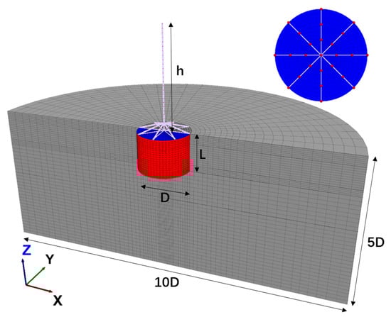
Figure 2.
Schematic model design in FLAC3D.
The bucket was constructed from steel with a Young’s modulus of 210 GPa and a Poisson’s ratio of 0.28. Its skirt had a density of 7.85 t/m3 and a wall thickness of 0.030 m. The cap, however, was modeled with a scaled density of 1.60 t/m3 and a thickness of 0.300 m, considering the internal bucket stiffeners. The bucket stiffeners could significantly enhance the performance of the bucket, and their use avoided unexpected local deformations [23]. To minimize the impact of the self-weight above the bucket on the vertical bearing capacity, the octagonal connection on the bucket was designed with high stiffness and low density. It is recommended to model the bucket using specific structural elements that can accurately simulate the normal and shear structure–soil interactions, while also adhering to the Mohr–Coulomb failure criteria. The Mohr–Coulomb failure criteria are described by the following equations:
where and are the normal and shear stiffness; is the tensile strength, and a gap will be formed if the tensile stress is greater than ; and are the cohesion and the residual cohesion, respectively; and is the friction angle between the structure and soil. Using the model in FLAC3D, the normal and shear stiffness could be determined based on the bulk and shear modulus of the adjacent soil [24]. The cohesion and friction angle at the interface were measured from the surrounding soil and modified by a reduction factor of 0.75 in these investigations. No residual cohesion was considered. Table 1 lists the properties used for describing the interface behaviors in these investigations. The properties on the internal and external sides of the MBF were the same.

Table 1.
Properties for describing the interface behaviors.
Using the modified cam clay (MCC) model is indeed a suitable method for simulating the behavior of normally consolidated and slightly consolidated soils. The MCC model can capture the key features of soil behavior during consolidation and shearing processes. It considers the soil’s compressibility, hydraulic conductivity, and strength parameters, making it an effective choice for analyzing the soil’s response to loading and deformation. The MCC model parameters listed in Table 2 were sourced from a paper by Hedge and Sitharam (2015) [25]. In Figure 3, a comparison between the simulated responses of the soil under isotropic consolidation and the laboratory records is presented.
Table 2.
Properties of modified cam clay model [25].
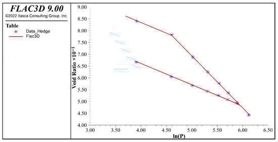
Figure 3.
Verification of MCC according to Hedge [25].
3. Model Validation
To verify the settings of the numerical model, a centrifuge test of an MBF with a diameter of 5.25 m and a length of 5.1 m conducted by Faizi was taken as an example [14]. During the test, the observed bearing capacity was recorded as 780 kN, with an eccentricity of 14.84 m. We compared the numerically estimated bearing capacity to the observed bearing capacity of the MBF. The original history trace depicted the relationship between the horizontal force and rotation. This relationship was estimated by applying a specific velocity of 1 × 10⁻⁷ m/s to the top of the beam elements. The data obtained from the analysis revealed noticeable oscillations due to the velocity-controlled mechanism employed in the simulation. To minimize these oscillations, it is recommended to reduce the magnitude of the applied velocity at the beginning of the simulation. Figure 4 also shows a logarithmic fitting line, which demonstrates an almost linear correlation for small rotations but gradually becomes nonlinear for larger rotations. A methodology to determine the bearing capacity based on this numerical simulation is to estimate the intersection between the linear line at the beginning and the tangent line coincident to the ultimate state. The numerically determined bearing capacity was approximately 760 kN, which was almost identical to the observed bearing capacity of 780 kN found by Faizi.
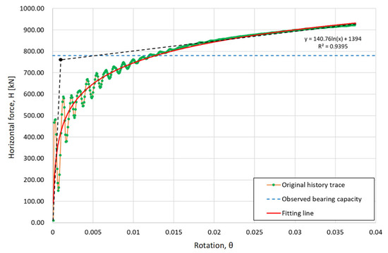
Figure 4.
Comparison of observed and predicted bearing capacities of mono-bucket (D = 5.25 m, L = 5.1 m, H = 14.84 m).
Figure 5 presents a schematic depiction of the load–deflection curve for the MBF. The curve exhibits prominent nonlinearity when the MBF undergoes deformation. Initially, the load–deflection curve develops linearly in a small deflection zone, which signifies that the foundation’s response remains proportional to the applied load. During this phase, the MBF undergoes deflection in a predictable and controllable manner. As the applied load increases, the load–deflection curve departs from linearity into nonlinearity, i.e., the yielding phase. Within this phase, the MBF experiences substantial deflection with marginal increments in the applied load. The ultimate bearing capacity, denoted as , can be determined by estimating the intersection of two tangential lines on the load–deflection curve. These tangential lines are estimated using the initial and final parts of the curve [14,17]. As mentioned, the deflection of the MBF must be optimal to ensure the power generation efficiency of the wind turbine. The permitted bearing capacity, denoted as , is determined based on the permitted deflection, . In most cases of offshore foundations, is in the linear zone of the load–deflection space. In Figure 5, corresponds to the deflection angle, , which indicates the load under which the wind turbine tower would undergo unacceptable deflection beyond the desired limitation.
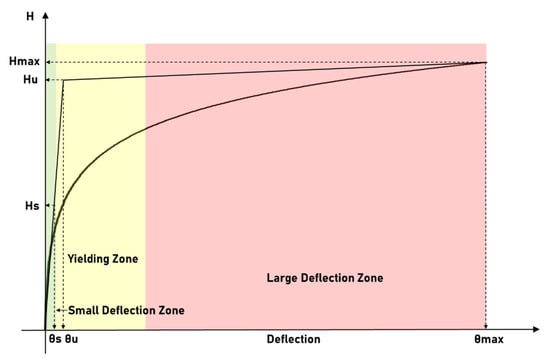
Figure 5.
Schematic illustration of load–deflection curve.
4. Mechanical Responses of Mono-Bucket Foundation
Figure 6 illustrates the deformation characteristics of the MBF under loading. The MBF deformed gradually until reaching an ultimate state, at which point a gap between the soil and bucket skirt formed and a slight heave could be observed. The displacements of the soil were primarily concentrated around the bucket. A rotation center (RC) was located at the center of the MBF bottom. Furthermore, Figure 7 illustrates the deformation characteristics of an MBF under right-pointing loads of 4000 kN, 8000 kN, and 20,000 kN. The MBF was designed with a diameter of 13.0 m and a height of 13.0 m, and the eccentricity level was 10.0 m. It became apparent that the RC of the MBF moved to the upper right when the loads increased. According to Faizi (2020) and Zhu et al. (2011), the depth of the RC in the ultimate state is approximately 0.8 times the length of the skirt, and the RC eventually reaches the skirt on the right-hand side of the MBF [14,25].
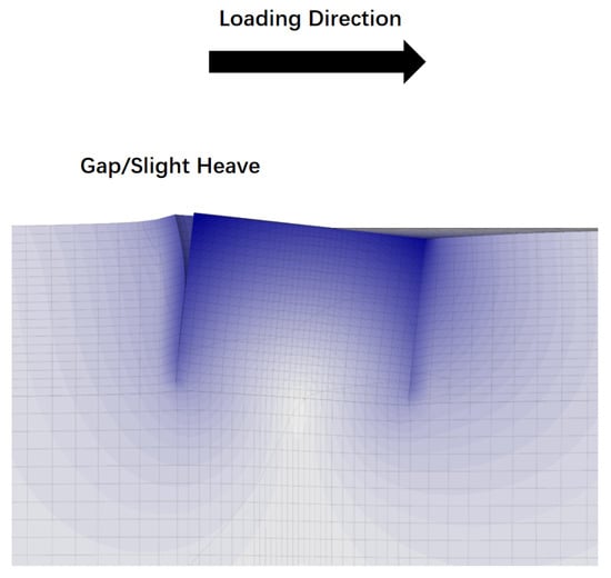
Figure 6.
Section view of deformed mono-bucket foundation.
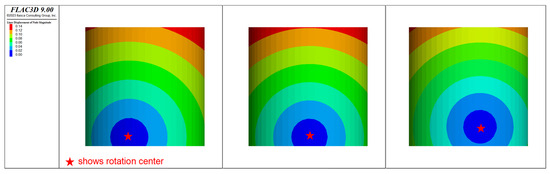
Figure 7.
Deformation characteristics of mono-bucket (D = 13.0 m, L = 13.0 m, H = 10 m) under various loads of 4000 kN, 8000 kN and 20,000 kN.
Figure 8, Figure 9 and Figure 10 represent the soil mechanical responses as the MBF was subjected to loads of 4000 kN, 8000 kN, and 20,000 kN, respectively. As the load increased, more of the surrounding soil was mobilized. Notably, when a load of 20,000 kN was applied, the numerical analysis exhibited poor convergence, indicating that the iterative method struggled to reach a stable solution within a reasonable number of iterations. Figure 8 shows the development of horizontal stress as the horizontal loads increased. The horizontal stress on the loading side increased noticeably and that on the anti-loading side decreased gradually. Some of the stress concentration zones around the MBF can be seen in deep blue. The curves of the horizontal stress and the depth estimated under different loads were plotted for both sides of MBF. The solid lines represent the horizontal stress distributions on the right side of the MBF; the dashed lines are for the left side. The blue curve, green curve, and red curve were determined under loads of 4000 kN, 8000 kN, and 20,000 kN, respectively. The horizontal stress above the RC on the right side increased as the loads increased, and the maximum value occurred near the middle above the RC. Below the RC on the right side, the horizontal stress was slightly relaxed. On the left side, the horizontal stress reduced almost to zero when an ultimate load was applied on the MBF. Figure 9 illustrates the vertical stress distribution around the MBF. Similar stress characteristics can be observed in Figure 9. However, a large zero-stress zone at the bottom built up, causing the MBF to have a low bearing capacity. Figure 10 shows the development of the shear stress due to the loads. A wedge-shaped area of concentrated stress developed on the right side and at the bottom of the MBF. The soil around the RC was less disturbed. Figure 11 shows plastic zones of soil for the mono-bucket foundation under various loads of 4000 kN, 8000 kN, and 20,000 kN, respectively. The soil began yielding on the anti-loading side but built up mostly on the loading side. The plastic zone in the ultimate state was highly coincident with the wedge-shaped area of concentrated shear stress.
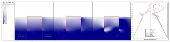
Figure 8.
Horizontal soil stress distributions for mono-bucket foundation under various loads of 4000 kN, 8000 kN, and 20,000 kN.
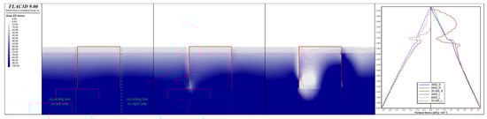
Figure 9.
Vertical soil stress distributions for mono-bucket foundation under various loads of 4000 kN, 8000 kN, and 20,000 kN.
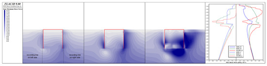
Figure 10.
Maximum shear stress distributions in soil for mono-bucket foundation under various loads of 4000 kN, 8000 kN, and 20,000 kN.
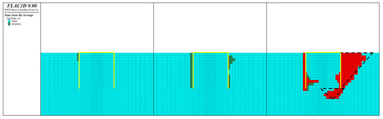
Figure 11.
Plastic zones in soil for mono-bucket foundation under various loads of 4000 kN, 8000 kN, and 20,000 kN.
5. Deflection-Controlled Bearing Capacity of Mono-Bucket Foundation
As investigated and simulated, an MBF behaves elastically within a small deflection zone, and the deformation characteristics control the design of MBFs and BBFs. Thus, developing a deflection-controlled method (DCM) for quickly estimating the size of an MBF would be helpful in the design process. The determination of the deflection-controlled considered the aspect ratio, vertical loads, loading eccentricity, and soil conditions. Table 3 lists the layout of the numerical simulations. The aspect ratio was in the range of 0.85~1.20, which could cover most designs of MBFs. The vertical loads were represented by the normalized form presented in Table 4, in which ρ stands for the density of the soil, g for gravity, D for the diameter of the MBF, and L for the length of the MBF. The normalized vertical loads, , are within the range of −0.30~0.20. A negative value represents a compressive load. The eccentricity, denoted as H, is within the range of 4 m~20 m; i.e., the eccentricity ratio is in the range of 0.31~1.54.
Table 3.
Layout of numerical simulations.
Table 4.
Normalized forms of the permitted loads.
Based on the simulation results, the effects of the aspect ratio, the loading eccentricity, and the vertical loads on the bearing capacity are demonstrated in Figure 12, Figure 13, Figure 14 and Figure 15. In Figure 12, several linear bending moments/horizontal force–deflection curves are presented considering different loading eccentricities. The local numerical oscillations were eliminated in the small deflection zone. The permitted bearing capacity was determined at a deflection constraint of 4.36‰. Figure 13 demonstrates the effect of the eccentricity on the permitted bending moment and horizontal force for an MBF with and . The permitted bending moment increased as H increased. However, the MBF could bear a smaller horizontal force when the eccentricity increased. Recognizing this is very crucial in the design of an MBF. Figure 14 illustrates the changes in the permitted bending moments as the aspect ratio increased for an MBF with H = 4 m and . A wide and short MBF exhibited a lower bearing capacity than a thin and deep MBF, since thin and deep MBFs can mobilize a greater (wedge-shaped) area of soil on the loading side compared to the anti-loading side. Figure 15 illustrates the effect of vertical loads on the permitted bending moments for an MBF with . It can be observed that the vertical loads had few effects on the permitted bearing capacity, though a slight increase occurred as the vertical loads switched from compressive to tensile. We had expected the MBF to stay elastic in a small deflection zone and some of the surrounding soil to deform plastically.
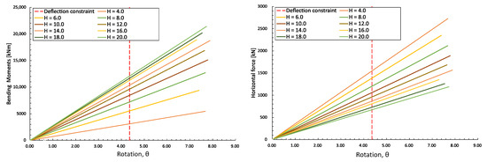
Figure 12.
Comparisons between bending moments/horizontal force–deflection curves considering different loading eccentricities.
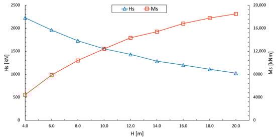
Figure 13.
Effect of eccentricity, H, on bearing capacity of mono-bucket foundation.
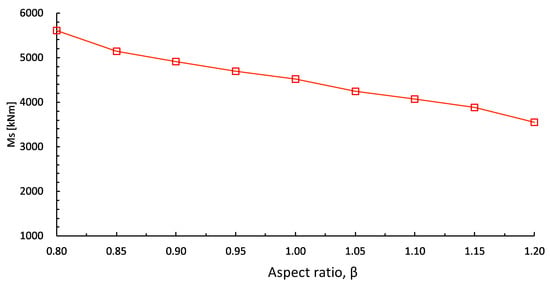
Figure 14.
Effect of aspect ratio on bearing capacity of mono-bucket foundation.
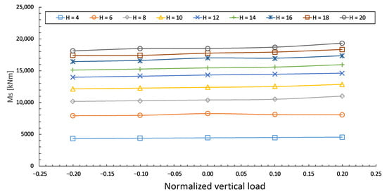
Figure 15.
Effect of vertical loads on bearing capacity of mono-bucket foundation.
To develop the deflection-controlled bearing capacity determination method, the permitted bearing capacity in Table 4 was normalized by the diameter, D, and length, L, of the MBF; the eccentricity, H; the friction constant, M; and the pre-consolidation pressure, . M and , implemented in the following equation, were employed to estimate the initial yield surface of the MCC, where and represent the mean pressure and deviatoric stress.
Figure 16 demonstrates the effect of the aspect ratio on the normalized bending moment for an MBF with = 0 and . It shows that the normalized bending moment was little affected as the shape of the MBF changed, which proves that consideration of the aspect ratio in the DCM is unnecessary. Figure 17 illustrates the effect of normalized vertical loads on the normalized bending moments for an MBF with . The normalized vertical load had little influence on the normalized permitted bending moment when the eccentricity was great. In contrast, the normalized vertical load affected the normalized permitted bending moment in the case of low eccentricity. A compressive load could decrease the normalized permitted bending moments. It was found that the soil could yield much more easily under a compressive load. The normalized permitted bending moments were similar to those when a great eccentric load was applied. The normalized permitted bending moments increased as the eccentricity ratio was reduced. Figure 18 illustrates the effect of eccentricity on the normalized permitted bending moments for an MBF with . The normalized permitted bending moment decreased with a greater eccentricity ratio. Figure 19 presents two almost-linear - curves in logarithmic space for an MBF with and , respectively. They appear to be linear in the dual logarithmic coordinate diagram. Thus, by best fitting the curves of shown in Figure 19, the generalized relationship can be expressed by
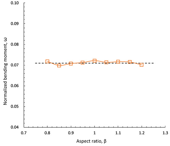
Figure 16.
Effect of the aspect ratio on the normalized bending moment for a mono-bucket foundation with = 0 and .
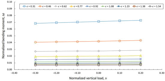
Figure 17.
Effect of vertical loads on the normalized bending moment for a mono-bucket foundation with .
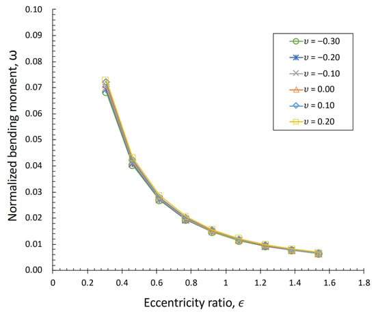
Figure 18.
Effect of the eccentricity on the normalized bending moment for a mono-bucket foundation with .
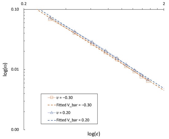
Figure 19.
Numerical and fitting curves in logarithmic space for MBF with and varying .
Based on the simulation results, the slope and intercept of the best-fitting line could be found using the following functions. The slope is a function of the normalized vertical load, the friction constant, and the swelling index. The intercept is a function of the normalized vertical load, the friction constant, and the compression index.
Based on the numerical simulations, the DCM is proposed. To validate the deflection-controlled method, it was applied to the design of a mono-bucket foundation for a wind farm project in southeastern China. The clay was near-homogenous and slightly over-consolidated. Using the DCM, the mono-bucket was estimated to have a size with a diameter of 11.5 m and length of 12.0 m, which was close to that in the final design.
6. Conclusions
This study presents a comprehensive numerical investigation into the mechanical behavior of mono-bucket foundations (MBFs) in clay under eccentric loading, culminating in the development of a deflection-controlled design method (DCM). The key findings and conclusions are summarized as follows:
- Numerical Validation: The FLAC3D model, employing a velocity-controlled approach with reduced initial velocities to minimize the oscillations, accurately predicted the bearing capacity of MBFs, showing close agreement with centrifuge test results. This validates the reliability of the numerical framework for analyzing MBF performance.
- Mechanical Response: The load–deflection behavior of MBFs exhibits distinct phases: an initial linear elastic response under small deflections, followed by nonlinear deformation as plastic yielding begins. Plastic deformation first occurs on the anti-loading side due to stress relaxation, while the loading side develops a wedge-shaped shear stress concentration zone, governing the MBF’s ultimate failure.
- Deformation Characteristics: Under loading, MBFs experience gap formation and soil heave around the skirt. The rotation center (RC) migrates toward the loading direction, stabilizing at approximately 0.8 times the skirt length (L) from the cap, without reaching the skirt edge. Stress redistribution causes compression on the loading side and relaxation on the anti-loading side and base.
- Design Parameter Sensitivity:
- a.
- Geometry: Thin, deep MBFs exhibit a higher bearing capacity than wide, shallow configurations due to greater soil mobilization.
- b.
- Eccentricity: Increasing the eccentricity enhances the moment capacity but reduces the allowable horizontal force, a critical consideration for design optimization.
- c.
- Vertical Loads: While vertical loads minimally influence the bearing capacity within serviceability limits, compressive loads slightly reduce the normalized bending moments, particularly at low eccentricities.
- Normalized Bearing Capacity: The proposed normalization framework, incorporating the eccentricity ratio (ε), vertical load (υ), and soil parameters (M, λ, κ), reveals a logarithmic linear relationship between the normalized bending moment (ω) and ε. The derived analytical expressions (Equations (6) and (7)) provide a practical tool for preliminary design.
- DCM Application: The DCM successfully guided the design of an MBF in southeastern China, demonstrating its efficacy for use with homogeneous clay. However, its applicability to heterogeneous soils requires further investigation.
Future Work: Extending the DCM to layered soils, incorporating cyclic loading effects, and validating its field-scale performance are recommended to enhance the method’s robustness to diverse offshore conditions.
Author Contributions
Conceptualization, X.G.; Methodology, X.G. and Z.J.; Software, X.G., G.P. and R.S.; Validation, G.P. and R.S.; Formal analysis, Z.J. and B.H.; Investigation, X.G., G.P., W.C. and Q.M.; Writing—review & editing, Z.J., B.H., C.W. and Q.M.; Visualization, W.C.; Supervision, W.C., B.H., C.W. and Q.M.; Project administration, R.S.; Funding acquisition, B.H. All authors have read and agreed to the published version of the manuscript.
Funding
This research was funded by “Pioneer” and “Leading Goose” R&D Program of Zhejiang grant number 2024C03031, and National Natural Science Foundation of China grant number 52271294.
Data Availability Statement
The data presented in this study are available on request from the corresponding author due to ongoing research.
Conflicts of Interest
Authors Xiangming Ge, Peng Gao, Zhenqiang Jiang, Weijiang Chu, Ben He, Ruilong Shi and Can Wang were employed by the company Power China Huadong Engineering Corporation (China); HydroChina Itasca R&D Center. The remaining author declares that the research was conducted in the absence of any commercial or financial relationships that could be construed as a potential conflict of interest.
References
- Oh, K.-Y.; Nam, W.; Ryu, M.S.; Kim, J.-Y.; Epureanu, B.I. A review of foundations of offshore wind energy convertors: Current status and future perspectives. Renew. Sustain. Energy Rev. 2018, 88, 16–36. [Google Scholar] [CrossRef]
- Jia, N.; Zhang, P.; Liu, Y.; Ding, H. Bearing capacity of composite bucket foundations for offshore wind turbines in silty sand. Ocean Eng. 2018, 151, 1–11. [Google Scholar] [CrossRef]
- Zhang, P.; Qi, X.; Ding, H.; Le, C.; Lin, Y.; Xiao, J. Bearing characteristics of mono-column composite bucket foundation in sand for offshore wind turbines. Ocean Eng. 2023, 280, 114870. [Google Scholar] [CrossRef]
- Yin, Z.-Y. Three-dimensional numerical modelling of progressive failure of caisson foundation in sand using a coupled FDM–DEM method. Ocean Eng. 2022, 253, 111332. [Google Scholar] [CrossRef]
- Wang, P.; Yin, Z.-Y. Micro-mechanical analysis of caisson foundation in sand using DEM. Ocean Eng. 2020, 203, 107240. [Google Scholar] [CrossRef]
- Gerolymos, N.; Zafeirakos, A.; Karapiperis, K. Generalized failure envelope for caisson foundations in cohesive soil: Static and dynamic loading. Soil Dyn. Earthq. Eng. 2015, 78, 154–174. [Google Scholar] [CrossRef]
- Houlsby, G.T.; Byrne, B.W. Design procedures for installation of suction caissons in clay and other materials. Proc. Inst. Civ. Eng. Geotech. Eng. 2005, 158, 75–82. [Google Scholar] [CrossRef]
- Gelagoti, F.; Georgiou, I.; Kourkoulis, R.; Gazetas, G. Nonlinear lateral stiffness and bearing capacity of suction caissons for offshore wind-turbines. Ocean Eng. 2018, 170, 445–465. [Google Scholar] [CrossRef]
- Kim, S.-R.; Hung, L.C.; Oh, M. Group effect on bearing capacities of tripod bucket foundations in undrained clay. Ocean Eng. 2014, 79, 1–9. [Google Scholar] [CrossRef]
- Kourkoulis, R.S.; Lekkakis, P.C.; Gelagoti, F.M.; Kaynia, A.M. Suction caisson foundations for offshore wind turbines subjected to wave and earthquake loading: Effect of soil–foundation interface. Géotechnique 2014, 64, 171–185. [Google Scholar] [CrossRef]
- Senders, M.; Randolph, M.F. CPT-Based Method for the Installation of Suction Caissons in Sand. J. Geotech. Geoenviron. Eng. 2009, 135, 14–25. [Google Scholar] [CrossRef]
- Ding, H.; Liu, Y.; Zhang, P.; Le, C. Model tests on the bearing capacity of wide-shallow composite bucket foundations for offshore wind turbines in clay. Ocean Eng. 2015, 103, 114–122. [Google Scholar] [CrossRef]
- Wang, X.; Li, D.; Li, J. Centrifuge modeling and numerical analysis on lateral performance of mono-bucket foundation for offshore wind turbines. Ocean Eng. 2022, 259, 111925. [Google Scholar] [CrossRef]
- Faizi, K. Development of an analytical model for predicting the lateral bearing capacity of caisson foundations in cohesionless soils. Ocean Eng. 2020, 13, 108112. [Google Scholar] [CrossRef]
- Houlsby, G.T.; Kelly, R.B.; Huxtable, J.; Byrne, B.W. Field trials of suction caissons in sand for offshore wind turbine foundations. Géotechnique 2006, 56, 3–10. [Google Scholar] [CrossRef]
- Houlsby, G.T.; Byrne, B.W. Suction Caisson Foundations for Offshore Wind Turbines and Anemometer Masts. Wind Eng. 2000, 24, 249–255. [Google Scholar] [CrossRef]
- Zhu, B.; Zhang, W.; Ying, P.; Chen, Y. Deflection-Based Bearing Capacity of Suction Caisson Foundations of Offshore Wind Turbines. J. Geotech. Geoenviron. Eng. 2014, 140, 04014013. [Google Scholar] [CrossRef]
- Tran, N.X.; Hung, L.C.; Kim, S.-R. Evaluation of horizontal and moment bearing capacities of tripod bucket foundations in sand. Ocean Eng. 2017, 140, 209–221. [Google Scholar] [CrossRef]
- Wang, L.Z.; Wang, H.; Zhu, B.; Hong, Y. Comparison of monotonic and cyclic lateral response between monopod and tripod bucket foundations in medium dense sand. Ocean Eng. 2018, 155, 88–105. [Google Scholar] [CrossRef]
- DNV-ST-0126; Anon Support Structures for Wind Turbines. Det Norske Veritas (DNV): HØvik, Norway, 2016.
- NBT 10105-2018; Anon Code for Design of Wind Turbine Foundations for Offshore Wind Power Projects. China Water & Power Press: Beijing, China, 2019.
- Achmus, M.; Akdag, C.T.; Thieken, K. Load-bearing behavior of suction bucket foundations in sand. Appl. Ocean Res. 2013, 43, 157–165. [Google Scholar] [CrossRef]
- Itasca Consulting Group, Inc. FLAC3D—Fast Lagrangian Analysis of Continua in Three-Dimensions; Itasca Consulting Group: Minneapolis, MN, USA, 2019. [Google Scholar]
- Hegde, M.A.M.; Sitharam, D.T.G. 3-Dimensional numerical analysis of geocell reinforced soft clay beds by considering the actual geometry of geocell pockets. Can. Geotech. J. 2015, 52, 1396–1407. [Google Scholar] [CrossRef]
- Zhu, B.; Kong, D.; Chen, R.; Kong, L.; Chen, Y. Installation and lateral loading tests of suction caissons in silt. Can. Geotech. J. 2011, 48, 1070–1084. [Google Scholar] [CrossRef]
Disclaimer/Publisher’s Note: The statements, opinions and data contained in all publications are solely those of the individual author(s) and contributor(s) and not of MDPI and/or the editor(s). MDPI and/or the editor(s) disclaim responsibility for any injury to people or property resulting from any ideas, methods, instructions or products referred to in the content. |
© 2025 by the authors. Licensee MDPI, Basel, Switzerland. This article is an open access article distributed under the terms and conditions of the Creative Commons Attribution (CC BY) license (https://creativecommons.org/licenses/by/4.0/).