1. Introduction
Conventional or geoponic agriculture has historically been the mainstay of global food production. However, its environmental impact is significant due to the intensive use of resources such as soil and water, as well as its use of unsustainable agronomic management practices [
1,
2]. More than 70% of the freshwater available on the planet is used for agriculture, while approximately 15% of arable land has lost its productive capacity due to inadequate management practices [
3,
4]. This situation is exacerbated by the expanding need to supply a growing population under increasingly unstable climatic conditions.
In response, alternative technologies have emerged that optimize resource use, such as hydroponics, aeroponics, and controlled environment agriculture, a term that encompasses, among others operations, controlled growth chambers [
5]. These allow agricultural experimentation to be conducted in small spaces and under controlled conditions [
2,
6]. Growth chambers, in particular, are used in research on plant physiology, crop propagation, and the development of new agronomic techniques. However, most of these systems are expensive, inflexible, or designed for specific commercial applications, which limits their adoption in academic, institutional, or research settings with restricted budgets [
7,
8,
9].
Recent studies have demonstrated a growing interest in modular and automated systems applied to controlled-environment agriculture. For instance, Bua et al. (2023) developed a modular smart hydroponic greenhouse integrating IoT and edge-computing architectures for precise climate regulation [
10]. Similarly, Patel et al. (2024) presented a hydroponic tower system designed with structural optimization to support modularity and reconfiguration; however, it is not directly intended for controlled environments [
11]. Additionally, Fue et al. (2020) reviewed modular robotic platforms for field operations, highlighting their scalability and adaptability to diverse agricultural contexts [
12]. These works confirm the relevance of modularity in agricultural innovation and underscore the opportunity to apply structured product platform methodologies to prototype development for experimental cultivation systems.
The development of automated or customized systems was noted within the reviewed literature; however, they often lack a methodological structure that enables their reuse or adaptation to multiple experimental contexts. Examples include, studies such as those of Nikolov et al. (2023) [
13] and Wright et al. (2023) [
14], who developed low-cost culture chambers but did not implement modular design strategies or product architecture. This methodological absence limits the experimental adaptability within these same prototypes and reduces scalability, hindering technology transfer to other projects or scientific communities.
In the face of these challenges, applying structured design methodologies in the early stages of prototype development represents a promising strategy. Design-based methodologies for developing product platforms and modular architecture have proven effective in various sectors, including manufacturing, household appliances, transportation, and consumer products [
15,
16]. Recent studies have documented their application in the design of coffee makers, bicycles, and electronic systems [
17,
18]. This type of design methodology prevents future problems by providing sufficient information and employing an analysis process in product development, requiring a lower expenditure of resources [
19]. However, its adoption in the agricultural industry remains limited. Suñer (2017) observed that the only way to integrate modular design within the agricultural sector is through machinery [
20], which would be impossible without the development of prototypes, namely, agricultural experimental devices. These devices are even scarcer, especially when it comes to controlled cultivation. This gap represents an opportunity to expand the scope of these methodologies to include applications with a high potential for social and scientific impact.
Modular design provides critical advantages that include scalability, which enables the incorporation of new functions; ease of maintenance; and the ability to adapt to different contexts or user requirements without redesigning the entire system [
21]. Likewise, the implementation of a product platform enables the creation of a standard base from which to derive multiple variants, thereby optimizing resources and development time [
22]. These features are especially relevant in research environments, where experimental objectives frequently change and available resources are limited.
This work proposes the application of a conceptual design methodology based on functions related to the user’s needs (customer-needs-driven design) for the development of a functional prototype of a cuttings growth chamber with modular architecture and a product platform. The methodological proposal suggested by Stone et al. (2008) [
22] is similar to the logical framework design methods mentioned by Cross (2002), as it covers design aspects such as the establishment of functions, the determination of characteristics, and the generation of alternatives [
23] but further allows for the development of a scalable platform that enables the integration of lighting or irrigation systems, sensors, or other components in the form of modules according to the needs of each investigation.
The primary scientific contribution of this work lies in demonstrating how a structured design methodology can be applied in experimental agricultural development contexts to create scalable, adaptable, and low-cost solutions that enable the optimal development of technology for this industry. This will lay the groundwork for future technology transfer to educational institutions, rural communities, or laboratories with limited resources, where this type of device can serve as a functional and accessible tool for innovation and experimentation. This will enable technological development to focus on the propagation and cultivation of plants, not only for green leafy vegetables or food in general but also for the cultivation of plants in danger of extinction or those with medicinal value whose cultivation in controlled environments has proven beneficial [
24].
2. Theoretical Framework and Fundamentals of Modular Design
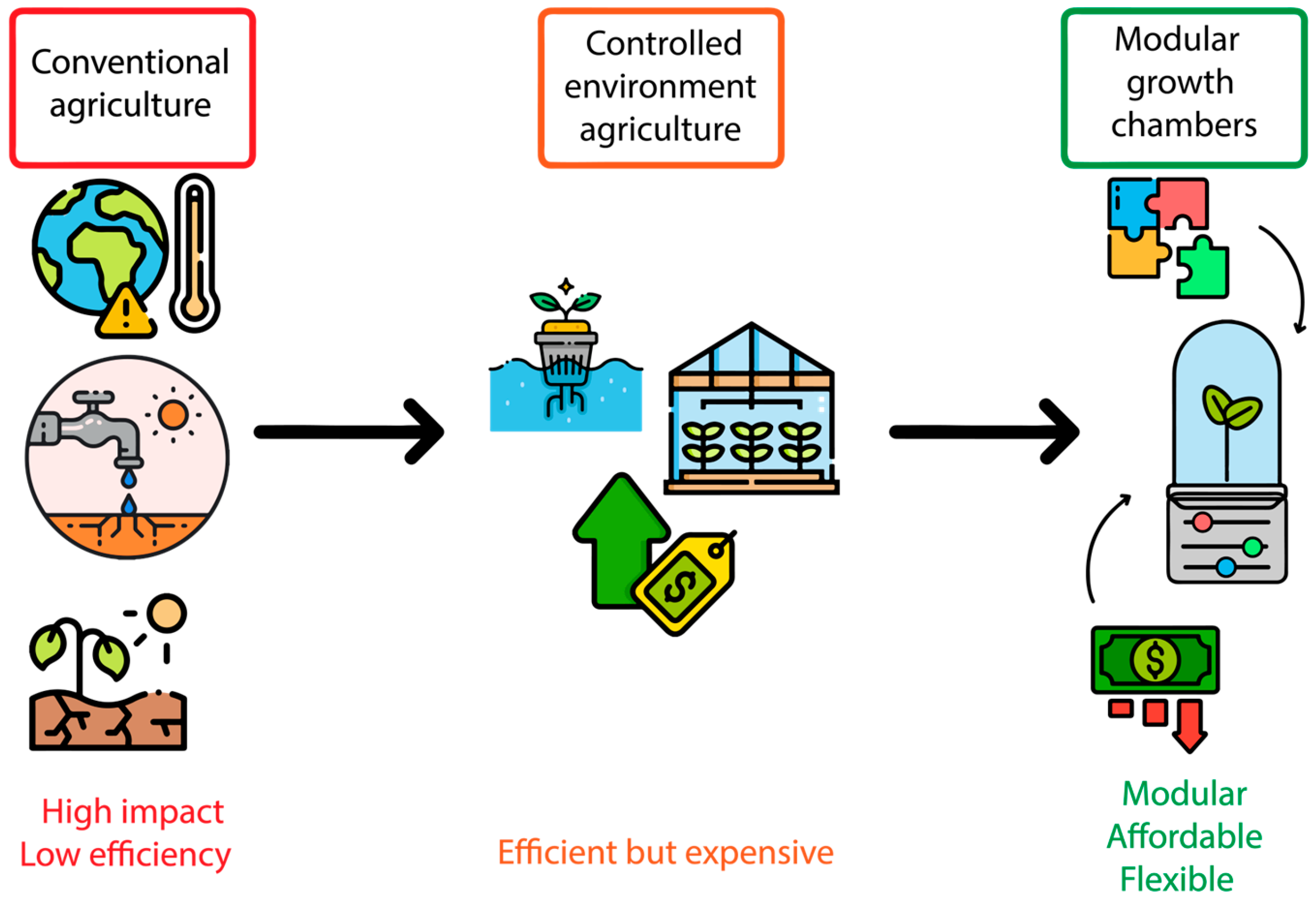
Figure 1 summarizes the conceptual transition that motivates this work, from the environmental and economic limitations of conventional agriculture, through the rise of controlled-environment techniques, towards the development of low-cost modular systems that democratize access to plant experimentation.
2.1. Design of Functional Prototypes in Applied Research
In agricultural research contexts, particularly in experimental plant propagation studies, technological resources are often limited. This constraint has driven the creation of low-cost, functional prototypes, which, while allowing the execution of specific experiments, frequently lack scalability and adaptability [
18]. These prototypes are built using an ad hoc approach, which is defined in the
Cambridge Dictionary as, “made or happening only for a particular purpose or need” [
25]. Consequently, prototypes designed with an ad hoc approach are intended to quickly solve specific problems without considering potential reuse in future applications outside their original purpose.
Unlike commercial products with long development cycles, in the academic and experimental environment, it is necessary to implement methodologies that accelerate the design process without compromising functionality or the possibility of evolution. Hence, the importance of applying systematic strategies, such as structured conceptual design, from the early stages is crucial, particularly when a single system is expected to adapt flexibly to diverse experimental needs [
26].
2.2. Product Platforms: Definition and Applications
A product platform comprises standard components, interfaces, and parameters that serve as the basis for developing a family of derivative products [
15]. This approach has been widely adopted in industrial sectors, such as the automotive, household appliance, and electronic device industries, enabling cost optimization, reduced development times, and improved adaptability to diverse market needs [
27].
In the field of experimental design, especially regarding agriculture or biological engineering, this approach is rarely adopted. However, its potential is considerable, as it enables the construction of a common technological base to which modules can be added, modified, or substituted, depending on the variables studied [
22]. Thus, a single growth chamber, for example, could be adapted to different types of irrigation, lighting, or monitoring by simply reconfiguring its modular structure or adding extra components that allow functions to be adapted according to the needs and objectives of the experiments.
2.3. Modular Architecture: Principles and Applicability
Product architecture defines how a system’s functions are assigned to its physical components. According to Ulrich and Eppinger (2012) [
16], there are two fundamental types: integral architecture, where functions are highly interconnected and components are difficult to modify, and modular architecture, where independent subsystems interact through well-defined interfaces.
Modular design offers crucial advantages for technological evolution, as it facilitates maintenance, allows for partial upgrades without requiring the redesign of the entire system, and promotes the reuse of components [
21,
28]. In design engineering, module identification heuristics (dominant flow, branched flow, conversion–transmission) have been used to transform functional models into physical architectures, supporting technical decisions from the early stages [
17].
A modular architecture would not only optimize the design from a technical perspective but also establish a strong technology transfer component, allowing modular prototypes to be easily disassembled, adapted, and rebuilt by different users, thereby fostering local know-how and technological innovation.
2.4. Applicability in Agricultural Systems and Experimentation
Despite the wide range of modular design applications in various areas, such as the mechanical, electrical, electronic, design, and architecture sectors, its adoption in the agro-industrial or agricultural fields is limited and carried out indirectly [
20]. This limitation is even more pronounced when considering an experimental approach. Some studies, such as those of Nikolov et al. (2023) and Wright et al. (2023) [
13,
14], have addressed the systematic design of growth chambers or agricultural devices through formal methodological strategies of experimentation, where low-cost culture chambers integrating monitoring sensors were designed. These experiments are similar to the those in the work of Bua et al. (2023), which is based on implementing and testing the correct functioning of modular monitoring components in a hydroponic greenhouse [
10], and Fue et al. (2020), who focused on the component architecture of a robot dedicated to cotton harvesting [
12]. However, these methodologies are not guided by the design area, thus lacking the benefits of applying a platform or modularization methodology to the experimentation and research process.
This shortcoming represents an opportunity for innovation. The development of modular prototypes for controlled agricultural systems would not only facilitate experimentation with different variables (temperature, humidity, time, and type of lighting or irrigation) but also allow adapting these same devices to the latest needs and experimental objectives with a minimal additional investment of time, effort, and even money. In addition, by applying a design methodology focused on user needs (as proposed by Stone et al., 2008 [
22]), the relevance and applicability of the product are strengthened, aligning the methodology with the real needs of researchers, technicians, or students in low-budget contexts.
The present work aims to address this methodological gap by demonstrating how conceptual design based on modular platforms and architectures can serve as a strategic solution for developing functional prototypes in experimental agricultural environments. This approach is expected to not only improve the efficiency of the design process but also promote scalability, technology transfer, and democratic access to useful technologies for plant experimentation.
Recent open-source initiatives such as FarmBot [
29] and MIT’s OpenAG Personal Food Computer [
30] have explored the use of modular cultivation platforms for experimental agriculture, reinforcing the relevance of the methodological approach proposed in this work. FarmBot, an open-source CNC farming robot, enables configurable, automated irrigation, planting, and monitoring—highlighting scalability, repeatability, and modularity for research applications [
29]. Similarly, the Open Agriculture Initiative has developed modular “Food Computers” that support decentralized, sensor-driven experimentation in controlled environments [
30,
31]. These examples underscore a growing interest in scalable, adaptable systems that closely align with the aims and approach of the present work, while demonstrating the practical viability of applying systematic design methodologies to agricultural experimental devices.
3. Materials and Methods
This study adopts a conceptual design methodology focused on user needs for the development of a modular product platform applicable to a cuttings growth chamber. The approach is based on the methodological framework proposed by Stoneet et al. (2008) [
22], which enables the translation of customer needs into functional models and scalable product architectures. The methodology is developed in three main phases—needs analysis, functional modeling, and product architecture definition, in addition to the generation of a conceptual design employing an approximate geometric layout of the actual case study. This allows for exploration of the possible organizations of the modules, thus obtaining a better understanding of how the conceptual design will be physically represented in the near future [
32].
3.1. Sample Selection Criteria
Since this study is oriented towards the exploration and application of a design methodology focused on user needs for the development of a modular cuttings growth chamber product platform, the selection of participants was based on the following criteria:
Relevance of the participant’s knowledge, i.e., individuals with experience or knowledge in areas related to controlled agriculture, system automation, product design, or applied engineering were selected.
Diversity of contexts of use, seeking to include participants who represented different application environments for the planned system, such as educational, small-scale urban, or academic environments.
Critical perspective and reflective capacity were prioritized in the inclusion of people capable of critically evaluating design proposals and participating in technical co-creation or technical discussion processes to facilitate an exchange of high-quality ideas that can improve design proposals.
These criteria, together with logistical limitations and access to more specific populations, resulted in the selection of only four people with varied knowledge and different approaches, but who converged on a common point: the research. Each contributed relevant and specific information that enriched the needs analysis, which is the basis of the methodology implemented in this research. Therefore, this number was sufficient for implementing the method, allowing for a detailed and coherent analysis of the data. The selection of participants (
n = 4) was based on a focused expert elicitation strategy, targeting individuals with specific and direct experience in the development, use, or evaluation of controlled-environment propagation systems. The selected participants were professionals with several years of practical experience in designing, developing, prototyping, monitoring, and automating plant growth chambers. Their profiles included postgraduate-level academic training and active involvement in research projects related to system implementation and testing. This small number of participants aligned with the methodological principles of conceptual design research. Several foundational studies support the use of small but expert samples in early-stage requirement elicitation: (i) Nielsen (1994) demonstrated that even as few as five users can yield the majority of insights during usability testing, highlighting that each user provides unique and valuable input [
33]; (ii) Blessing and Chakrabarti (2009) [
34] emphasized that a sample size of one person can be as valuable as a sample size of 1500 persons, depending on the type of study. Sample size can be as big or small as needed in any phase of development when the members possess contextual expertise or any characteristics that could influence the outcome of a particular study [
34]; and (iii) Otto and Wood (2001) advocated for expert elicitation, where knowledgeable individuals inform functional modeling and requirement capture [
26]. Therefore, a cohort of four expert participants in this study is consistent with accepted practices in design methodology and ensures a high-quality, focused input base for the functional development of the prototype.
3.2. Methodological Approach Adopted
The methodology employed adhered to the logic of structured conceptual design, which aims to transform qualitative information from the user into technical representations of the product. This approach consists of three fundamental steps [
22]:
Identification and categorization of user needs.
Development of functional models (base and variants).
Construction of a product architecture compatible with a modular platform.
This methodology has been successfully applied to consumer products, including coffee makers, electronic equipment, and portable tools. However, its implementation in low-budget experimental devices, such as those used in controlled agriculture, represents a relatively unexplored field. The incorporation of this approach into agricultural systems could enhance design efficiency, facilitate the development of prototypes, and enable adaptation to various experimental requirements at reduced costs [
16,
18].
The conceptual design process in this study was guided by a set of general design objectives that reflect the practical needs of controlled-environment agricultural systems. These objectives included: (i) achieving functional modularity, enabling individual subsystems to be independently developed and replaced; (ii) supporting scalability, allowing the system to be adapted to diverse experimental needs without full redesign; (iii) ensuring low-cost construction using widely available materials and components; and (iv) promoting user accessibility and ease of assembly, such that researchers with limited technical resources can replicate or adapt the system. Although this article focuses on conceptual and methodological development, these objectives shaped the architecture and functional decomposition of the system. Other specific technical objectives, such as energy optimization, lighting control, or environmental precision, are reserved for subsequent validation in the physical implementation phase. Similarly, the validation of conceptual design objectives, such as functional modeling and modular architecture, in later stages, including functional modularity, scalability, low-cost construction, physical integration, and interface standardization, are reserved for further work.
3.2.1. Analysis of User Requirements
The first stage involved identifying the functional needs necessary for the development of the prototype. For this purpose, semi-structured interviews were conducted with a group of four researchers who are potential users of the system, and they provided 55 needs related to the operation, monitoring, flexibility, and physical environment of the growth cabin.
Each need was evaluated in two dimensions:
Each part of the evaluation was addressed individually so that none of the users were aware of the other’s responses, thereby preventing communication from influencing individual responses.
A quantitative table was then drawn up to classify the needs according to their weight and the frequency with which they were mentioned.
Base needs: mostly those with a weight of ≥3 and a frequency of ≤(n/4), (where n = number of researchers interviewed), which, according to the methodology, are the leading candidates for base needs.
Differentiating requirements: requirements that do not meet the above-mentioned weight and frequency classification that serve as auxiliary or specific functions useful for variants.
Following this quantitative analysis, a complementary qualitative review was conducted to identify redundancies and group-related needs and to eliminate those that were not necessary for the system’s basic operation. From this rigorous analysis, 26 basic needs were identified, thus allowing for the construction of a solid base for the development of the functional model and the system modules.
3.2.2. Functional Modeling of the System
In this phase, functional models were developed using the approach proposed by Stone and Wood (2000) [
32] based on energy, material, and signal flows [
35]. The following structured sequence was employed.
- 4.
Black box model: inputs (energy, water, and data) and outputs (rooted cuttings and monitoring data) were represented.
- 5.
Function chains: sequential and parallel subfunctions within the system were detailed.
- 6.
Complete functional model: all basic functions were integrated into a single diagram, visualizing relationships and possible modularity points.
Subsequently, two variant functional models were developed, incorporating differentiating functions such as different types of irrigation (aeroponic, drip) and specific sensors. These variants demonstrated that the base functional model was robust and scalable enough to support additions without compromising the overall system architecture.
3.2.3. Product Architecture Definition
To build a modular architecture consistent with the functional model, three heuristics from the methodology proposed by Stone [
17,
22] were applied:
Dominant flow heuristics: linear trajectories of functions from the input to the output of the system were identified.
Branched flow heuristics: independent functional modules connected by shared flows were recognized.
Conversion–transmission heuristics: modules where transformations occur (e.g., electrical to mechanical energy) were isolated.
These heuristics made it possible to identify recurring modules such as the
The modules were represented in block diagrams, considering possible spatial configurations, interfaces, and future expansions. The possibility of implementing hybrid architectures (slot and bus type) was evaluated to facilitate the insertion of new components.
3.3. Application of the Methodology to the Case: Cuttings Growth Chamber
Once the methodology was established, it was applied to the specific case of a growth chamber for hydroponically propagated cuttings. This device was designed to enable the controlled rooting of plant cuttings under laboratory or greenhouse conditions, integrating functions for irrigation, thermal control, lighting, and environmental monitoring.
We proceeded as follows:
Based on the needs analysis, key components such as root and stem humidity sensors, temperature sensors, photoperiod control, water pumps, and data storage units were prioritized.
In the variant functional models, aeroponic and drip irrigation systems were specified as examples of design adaptability.
The resulting architecture enabled the visualization of a central structure (platform) with interchangeable modules, depending on the type of experiment.
Two conceptual design diagrams were developed, showing possible physical configurations of the prototype.
This case study demonstrates that a structured design methodology can be applied effectively in the development of low-cost agricultural devices, resulting in modular, scalable, and adaptable prototypes. The result not only responds to a specific need but also establishes a methodological basis that can be replicated in other contexts.
3.4. Other Methodologies Considered
The use of design methodologies specifically applied to agricultural design is identified primarily in the development of modular machinery, as Suñer concludes in her thesis [
20]. If used, these are generally employed to develop modular architectures for the experimentation with or production of specific plants. However, the possibility of turning this design into a product platform that can be used, modified, and reused as needed is not taken into account. Such considerations would benefit users in terms of time savings and the costs of subsequent developments by favoring the reuse of parts or modules of a first robust design in different subsequent redesigns, without the need for a rigorous redesign.
This is the main interest in the development of a functional prototype of a cutting growth chamber, where modularity and scalability allow for conducting different experiments with fluctuating variables, without requiring the redesign and complete reconstruction of the chamber. Instead, only minor modifications are necessary to achieve the different objectives.
For this reason, a literature review was carried out to select the design methodology from the following:
TRIZ, translated from Russian, means the “theory of inventive problem-solving”. It is a methodology for designing and developing product families based on product platforms. Although it aims to generate innovative solutions, it does not provide modularity or scalability strategies; instead, it focuses on identifying and resolving design contradictions. For example, increasing the strength of a material may imply an increase in weight, which can be counterproductive [
36]. Therefore, this method was eliminated.
Gershenson proposes a modular design methodology and even suggests a method for determining the modularity relationship. However, this method is aimed more at redesign than at creating a design from scratch. Nevertheless, it was not ruled out as a helpful tool that could be used in the future [
37,
38].
Finally, the methodology used in this paper was proposed by Stone, which encompasses the design process based on customer needs, product platform design, and modular design [
17,
22,
32]. These last two points make it especially useful for scalable designs, allowing for, if necessary, the integration of modules, components, or even software without conflicts. This would also allow the same design to expand its functions, without requiring a redesign from scratch, and to be used in different contexts.
4. Results
4.1. Results of the Needs Analysis
The first phase of prototype development involved identifying and classifying the system’s functional requirements. For this purpose, semi-structured interviews were conducted with the group of four users, who provided a total of 55 needs related to the operation, monitoring, flexibility, and environmental conditions of a growth chamber for cuttings used in experimentation.
Each need was evaluated according to two criteria:
Frequency of occurrence, i.e., the number of participants who mentioned the need;
Relative weight assigned, i.e., the importance perceived by the user, on a scale from 0 (not important at all) to 5 (very important).
These data were systematized and tabulated in
Table A1 in
Appendix A, which presents the complete list of needs, together with their frequency of mention and the average weight assigned by the interviewees. From this table, a scatter plot was constructed (see
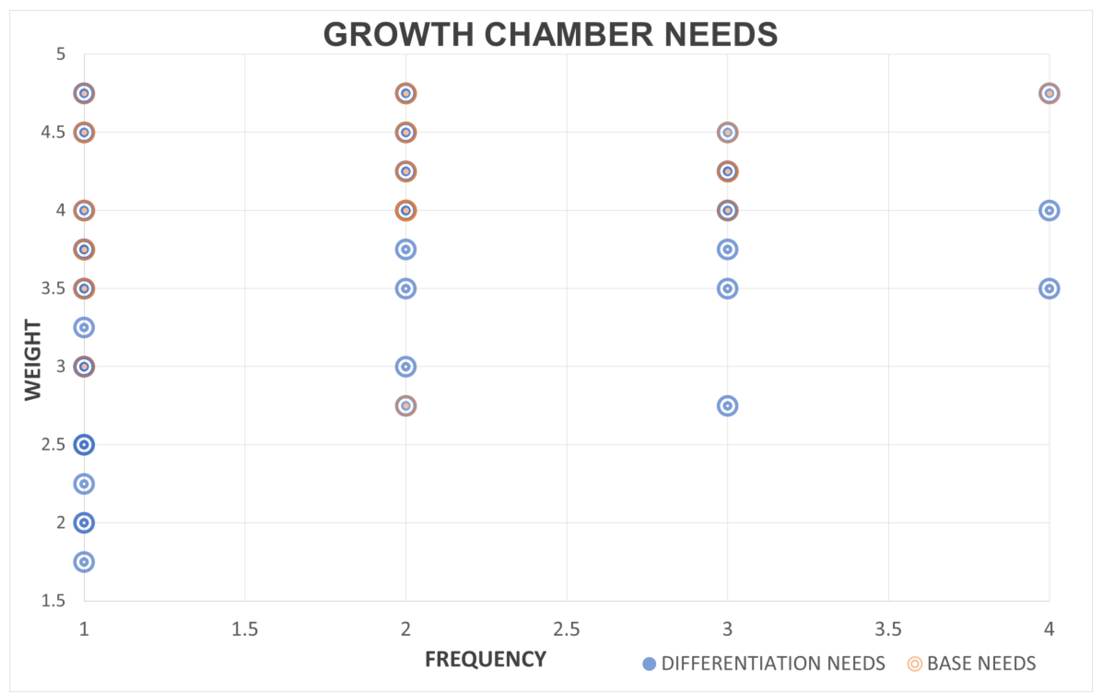
Figure 2). The scatter plot illustrates 55 identified user needs, evaluated by frequency (x-axis) and weight of perceived importance (y-axis, scale 0–5). Following the methods of Stone et al. (2008) [
22], needs classified as “basic requirements” (essential to the core functionality of the platform) are those meeting the base criterion (weight ≥ 3, frequency ≤ 1), which appear in the upper left quadrant of the scatter plot. Although a significant concentration of core needs falls within this preliminary classification, a qualitative refinement, detailed in
Section 4.1, enables the inclusion of additional interconnected needs, thereby ensuring a solid foundation for the modular platform.
The result was a final selection of 26 base needs, representing a 52.72% reduction, without compromising system functionality, thereby optimizing resources to focus on the requirements essential for the platform design. (see
Appendix A,
Table A2, for a list of the selected base needs). These basic needs are also identified in the scatter plot (see
Figure 2).
These needs are considered essential and represent the functional core of the product platform. The remaining requirements were classified as differentiating requirements applicable to the design of future variants. It is this debugging and classification that allowed us to improve the clarity of the functional model and to anticipate combinations and dependencies between requirements.
For example:
The need to monitor internal temperature also implies controlling the airflow and ensuring adequate thermal insulation.
The implementation of different irrigation systems, such as drip or aeroponic types, requires an open and modular architecture in the hydraulic components.
Overall, this needs analysis laid the groundwork for the subsequent phases of development by defining both mandatory platform constraints and possible modular extensions to accommodate future experimental requirements.
4.2. Functional Modeling: Basis and Variants
Following the base needs analysis (
Table A2), the functional model of the product platform was developed using the functional decomposition methodology proposed by Stone and Wood (2000) [
32] and Ulrich and Eppinger (2012) [
16]. This methodology involves representing a product through its elementary functions, structured in the form of logical chains that describe the flow of energy, materials, and signals within the system. These flows are represented by colors, which remain unchanged unless a flow transformation occurs, e.g., an electrical energy flow transformed into a signal (see
Figure 3 and
Figure 4).
The functional modeling process was structured in three levels, which will be described below.
4.2.1. Basic Functional Model
We began with a black box model, which defines the inputs and outputs of the system, without detailing the internal components that correspond to the 26 base requirements. This scheme shows the inputs of energy, water, and user commands, as well as the expected outputs: rooted cuttings, measured data, and outputs of the components that achieve the controlled environmental conditions. The resulting black box model is shown in
Figure 3.
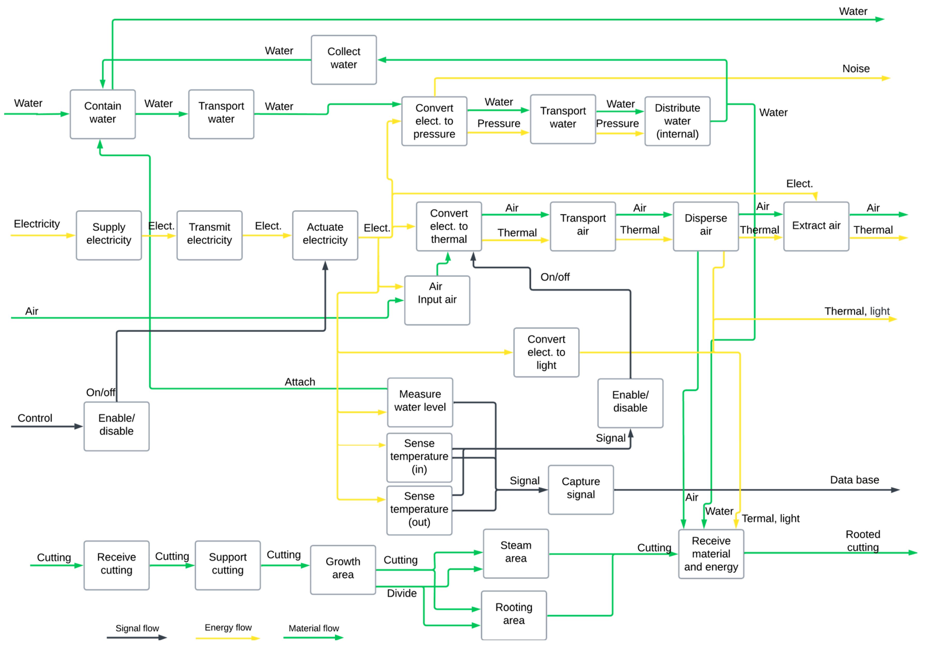
From this model, the detailed functional model was constructed (see
Figure 4), where the inputs are connected through specific sub-functions to achieve the desired outputs. The functions are organized in sequential and parallel chains, according to the operational logic of the system, by developing sub-functions that would allow for “regulating temperature”, “hydrating roots”, “illuminating stems”, and “monitoring variables”, among others. The interaction between these functions reflects a potential modular architecture, allowing for the identification and functional flows within the system at a later stage. It should be noted that, although the definition changes in several of these subfunctions, the type of flow represented does not change. For example, when electricity is transformed into light, each remains a flow of energy.
4.2.2. Variant Functional Models
Based on the base functional model and the integration of differentiating needs (
Table A1 and
Table A2), two additional functional models were developed, representing variants of the prototype with expanded components or functions (see
Figure 5). These variants incorporate alternative irrigation systems and specific sensors that are not part of the base model.
Variant 1 incorporates aeroponic irrigation, humidity sensors, and a pH sensor integrated into the water container.
Variant 2 replaces the aeroponic irrigation system with a drip irrigation system, while maintaining the same sensors.
In variant 1 (see
Figure 5), the water flow is dispersed by sprinklers located in the root zone. A recirculation cycle returning water back to the tank is also included.
In variant 2 (see
Figure 6), water flows via gravity from the stem to the roots. The system features mechanisms for collecting and returning water to the reservoir, thereby emulating a closed cycle and facilitating water recirculation.
Both variants retain the structure of the base functional model, thus validating its robustness and consistency. Additional modules are integrated, without altering the primary functions of the system, demonstrating that the proposed architecture is indeed modular and scalable.
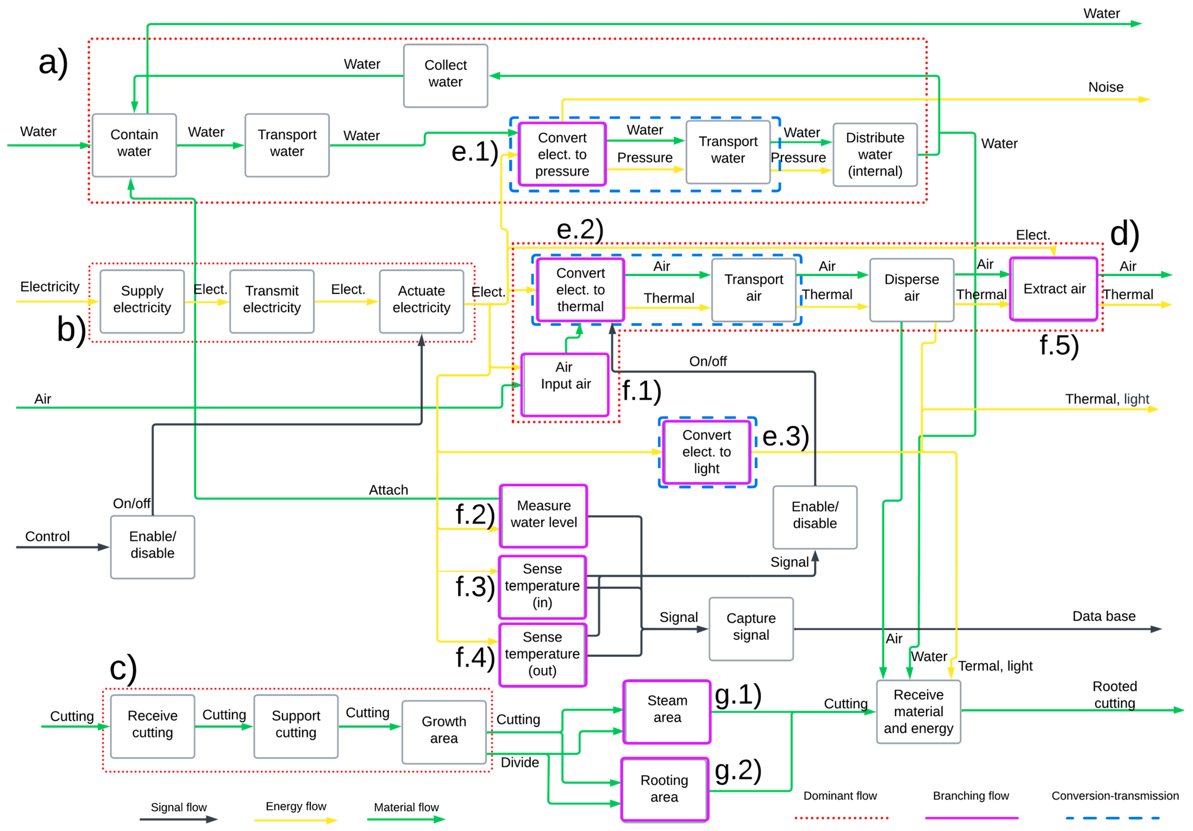
4.3. Application of Heuristics: Module Identification
With the base functional model and its variants clearly defined, a series of architectural design heuristics were applied to identify the functional modules of the system. These heuristics facilitate the transformation of the logical representation of functions into a proposed modular physical structure, adhering to the principles of flexibility, independence, and scalability.
The methodology used follows the approach described by Stone and Wood (2000) [
32], where three main heuristics are applied:
Dominant Flow Heuristic: identifies linear sequences of functions through which the same inputs (water, energy, signal) flow, without bifurcations.
Branching Flow Heuristic: detects functional branches that can operate as independent subsystems connected at a common point.
Conversion–Transmission Heuristic: highlights sub-functions in which transformations occur from one type of flow to another (e.g., electrical energy to mechanical energy), which generally defines natural boundaries between modules.
These heuristics were applied to both the base functional model and its variants, yielding consistent results that demonstrate the feasibility of implementing a modular architecture without compromising the system’s functionality.
4.3.1. Application in the Functional Model Variant with Aeroponic Irrigation
In
Figure 5, the sub-functions associated with the aeroponic irrigation system are grouped based on the following:
Dominant flow, i.e., the water supply for the irrigation, electric power, air conditioning module, and support and growth area for cuttings.
Conversion–transformation, i.e., using electrical energy for lighting, heat, and water pressure.
Functional bifurcation, i.e., the supply of electrical power to the components that require it (including sensors) and the physical division of the cuttings growth area.
In addition, specific components were identified for
Environmental monitoring using sensors for humidity, temperature, and pH levels.
Control and programming, including actuators and microprocessing units.
This modular grouping allows a physical implementation in which each of these subsystems can be assembled, upgraded, or replaced independently, as long as the defined interfaces are respected.
4.3.2. Application in the Functional Model Variant with Drip Irrigation
In
Figure 6, the modular structure is similar to that in the previous case, but the internal configuration of the irrigation module alters as the water flow trajectory changes from the stem zone to the root and then back to the collection area for water recirculation; this could constitute a secondary module for water management.
The remaining modules (lighting, growth area, heating, monitoring, and control) remain unchanged, providing evidence for the stability of the proposed platform architecture.
4.3.3. Comparison with the Baseline Functional Model
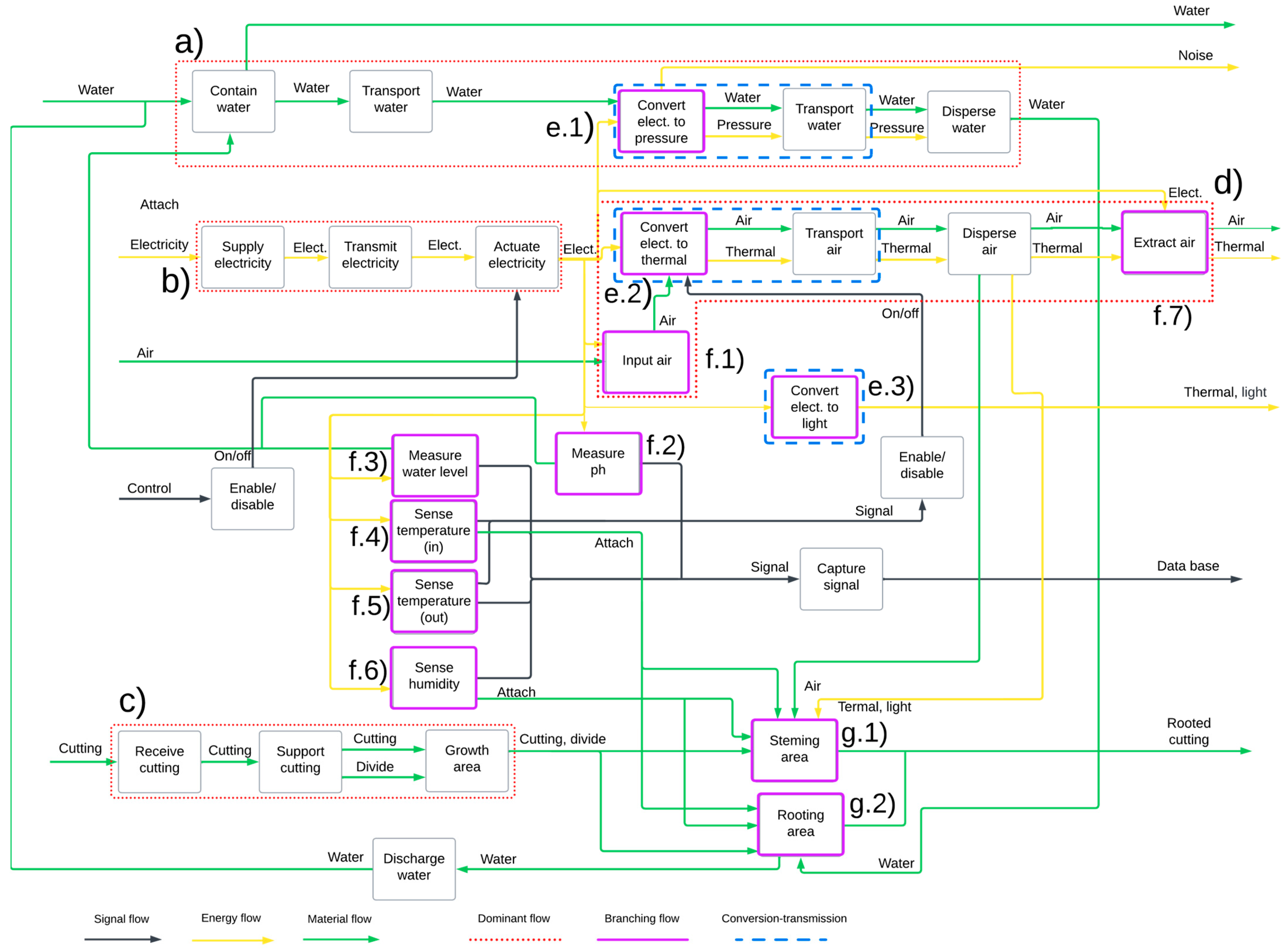
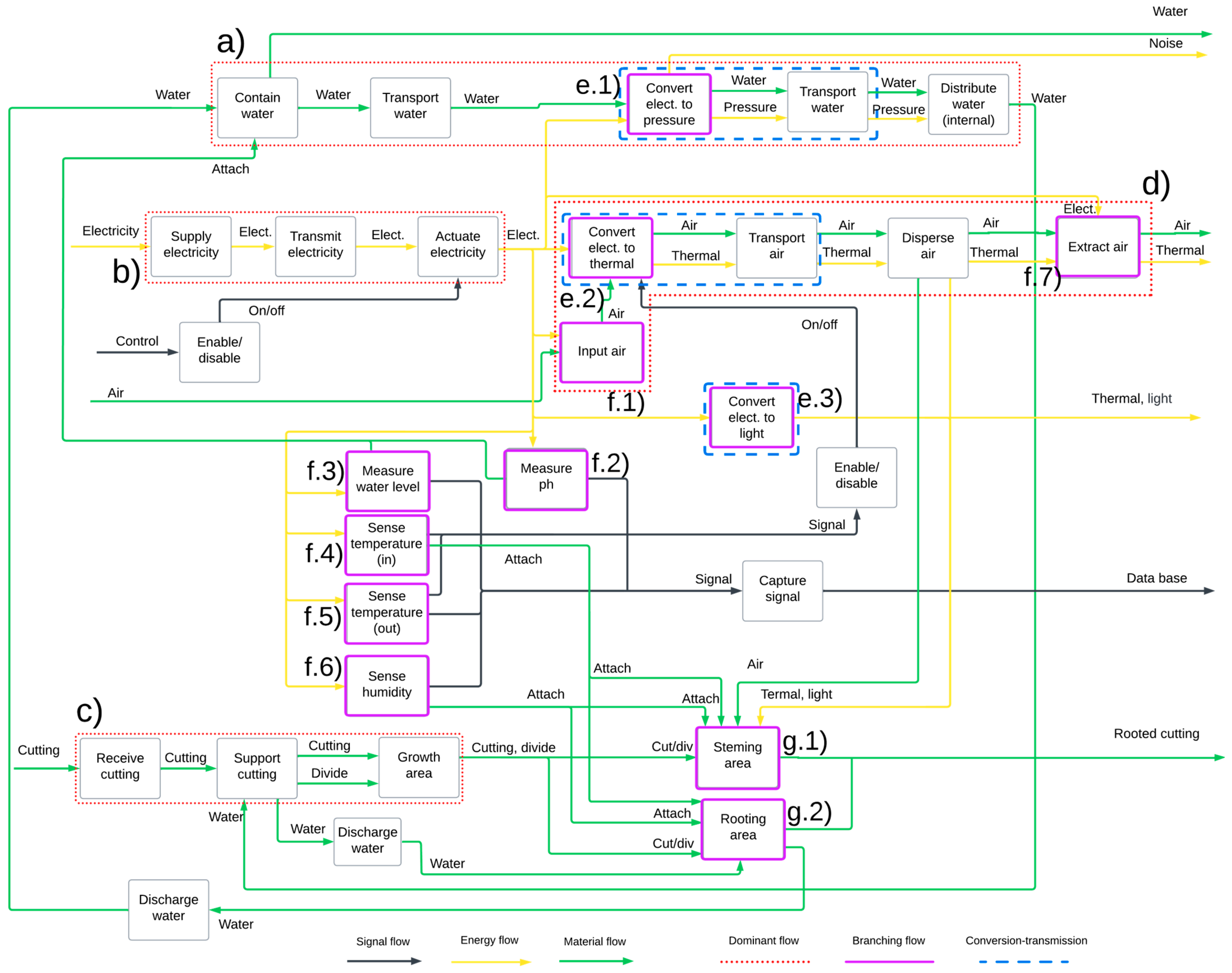
Figure 7 illustrates that when applying the heuristics to the base model, significant coincidences are observed with the modules detected in the previous variant models. Stone (2008) [
22] mentions that when different heuristics converge on the same set of functions, the validity of that grouping as an autonomous module is reinforced. In this case, modules that fulfill functions such as irrigation, lighting, and thermal air conditioning, among others, appear repeatedly, confirming them as stable modular cores.
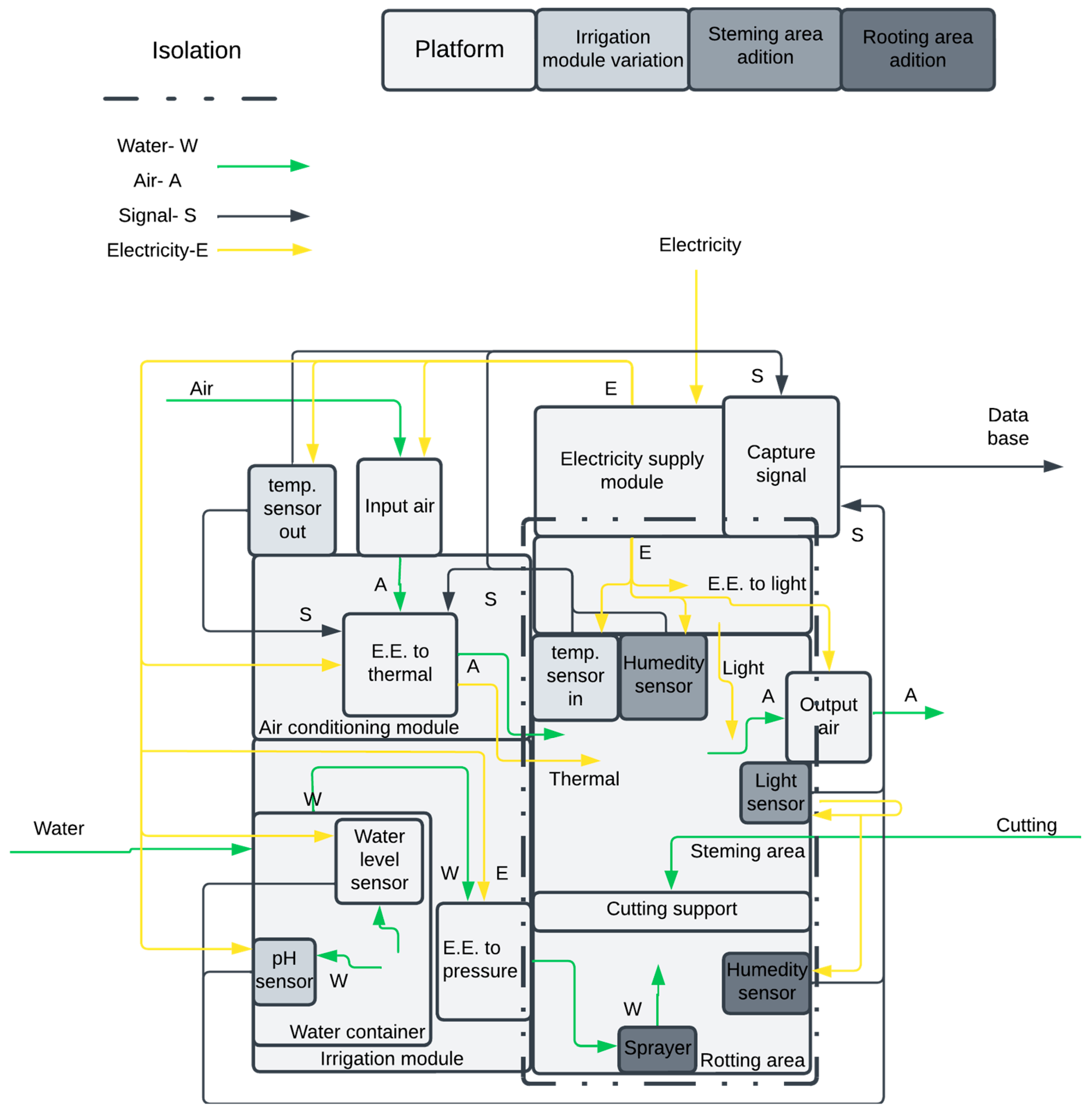
4.3.4. Physical Architecture Considerations
Based on the results obtained, it was feasible to implement a modular slot-type architecture in which each module is directly connected to a standard base structure. A bus architecture is also considered especially useful for handling the interconnection of sensors and control systems through shared protocols [
16].
This phase allowed us to consolidate a preliminary physical structure of the system, in which
Each module can be developed and evaluated independently of the others.
Technological upgrading is facilitated via components.
Prototype customization is enabled according to the objectives of each experiment.
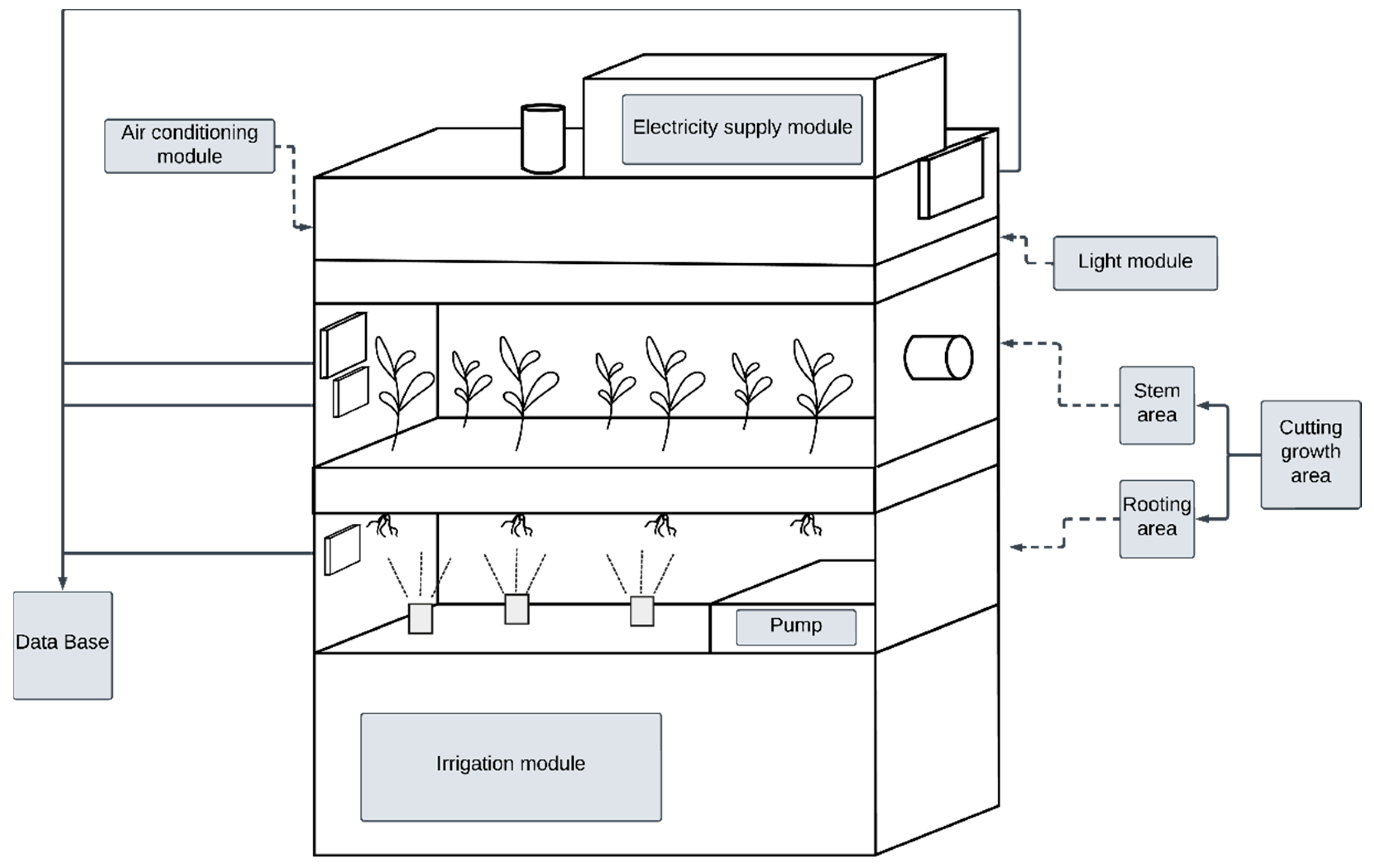
4.4. Conceptual Design: Block Diagrams
Once the modules were identified through functional analysis and the application of heuristics, we proceeded to construct the conceptual design of the cutting growth chamber. This stage translates the functional and modular architecture into a preliminary geometric and spatial proposal, usually represented by block diagrams that allow for the visualization of the
relative arrangement of the modules within the system;
possible physical and logical interfaces between components;
energy, material, and signal flow paths.
This representation does not yet imply a detailed CAD-level design or 3D modeling, but it lays the groundwork for later stages of design and physical implementation.
4.4.1. Proposed Modular Layout
Based on the variant functional models discussed in
Section 4.3, two different conceptual design configurations were proposed, based on variant 1.
In the design illustrated in
Figure 8, the following can be observed:
The aeroponic irrigation module is positioned in a peripheral location to minimize interference with other subsystems while maintaining water recirculation.
The control and programming module is housed on the external side, allowing direct access to microcontrollers and user panels.
The environmental monitoring module is distributed between the root zone and the stem zone, with strategically embedded sensors.
The lighting system is mounted at the top and oriented towards the area of leaf growth.
The air conditioning system and the power supply module are positioned at the top to prevent contact with water.
This configuration optimizes the gravitational flow of water in the recirculation system, allowing the sensors to be located close to the measurement point, without the need for extensive wiring.
In the design illustrated in
Figure 9, the following can be observed:
The growth area is directly connected only to the lighting module.
The irrigation module remains the same, except for its position, as it is located to the side of the growing area, and the air conditioning system is placed above it.
The location of the lighting and control module is maintained.
The sensors are distributed similarly but with an emphasis on measuring the impact of irrigation in the designated zone.
This configuration enables the adaptation of the same general cabin chassis to a different operating logic, without modifying the main structural modules. This reaffirms the effectiveness of the modular platform approach because, without the application of a modular design, this type of organization and reorganization of modules and components would not be possible.
While both irrigation systems (aeroponic and drip) were explored as part of the functional modeling process in
Section 4.3, the aeroponic system was selected as the basis for the block diagrams, owing to its stronger alignment with the modularity principles. Aeroponic systems often support a tighter integration of sensors and digital controls, thanks to their compact misting environment and reduced complexity in the fluid pathways [
39,
40]. These characteristics facilitate subsystem independence and interface clarity, in line with the design objectives outlined in
Section 3.2. As this work remains at the conceptual stage, it does not imply empirical superiority, and a quantitative comparison of performance awaits pending comprehensive physical testing.
4.4.2. Design Implementation Considerations
Although the block diagrams presented above are abstract representations, they serve several key functions:
They facilitate subsequent 3D modeling by establishing spatial relationships between modules;
They clarify the components and their possible behavior to anticipate assembly, maintenance, and access problems;
They allow for the exploration and comparison of design variants quickly before building a physical or digital prototype.
In the future, these diagrams can be converted into physical drawings, CAD models, or virtual simulations, integrating materials, tolerances, and mechanical and electrical interfaces.
It is suggested that the digital implementation start with parametric 3D modeling, where each module is defined as an independent entity but is connectable through a standard system of slots or ports.
4.4.3. Value of Conceptual Design in the Process
Conceptual design bridges the gap between abstract functions and physical structure, in addition to
In this case, the conceptual design confirms that the defined modules are not only functional but also physically integrable within a logical and reusable architecture. This positions the prototype as a scalable, replicable solution with the potential for transfer to other agricultural experimental contexts.
4.5. Modular Synthesis of the Proposed Design
In conclusion, an overview of the designed system is presented, which synthesizes all the identified functional modules and their interactions. This overview facilitates an understanding of the system as a whole and provides a basis for future physical implementations and experimental adaptations (see
Figure 10).
5. Discussion
The results obtained demonstrate that the design methodology, utilizing product platforms and modular architecture commonly used in industrial sectors, can be effectively adapted for the development of experimental agricultural prototypes. The identification of 26 base needs from the initial 55 using quantitative criteria (weight ≥ 3, frequency ≤ n/4) and complementary qualitative analysis proves the robustness of the filtering process proposed by Stone et al. (2008) [
22]. This 53% reduction in initial requirements, without compromising system functionality, indicates that the methodology allows teams to channel their resources into the features with the greatest functional return.
The successful development of variant functional models (aeroponic and drip) that retain the base structure confirms the architectural stability of the proposed modular design. This feature is particularly valuable in agricultural research contexts, where experimental objectives change frequently, and resources are limited. The ability to adapt the system by replacing or adding specific modules, without requiring a complete redesign, represents a significant advantage over the ad hoc approaches prevalent in the reviewed literature.
Unlike Wright et al. (2023) [
14] and Nikolov et al. (2023) [
13], who developed low-cost cameras with fixed structures, this study provides a methodology that prioritizes adaptability and scalability. While previous approaches address specific needs, the modular approach enables multiple configurations to be derived from a common platform, thereby optimizing the initial investment, facilitating technology transfer, and addressing varying needs.
The absence of structured methodologies in experimental agricultural design, as identified by Suñer (2017) [
20], is directly addressed through the systematic application of modular identification heuristics. The identified modules (irrigation, lighting, monitoring, control) emerge consistently in both variants, validating the universality of these functional components in controlled cropping systems.
Quantitative needs analysis, functional modeling, and validation through heuristics strengthen the credibility of the results. Specifically, the application of the three design heuristics provides multiple perspectives for modular identification, increasing the robustness of the process. The convergence of the results among different heuristics strengthens the validity of the proposed modular groupings. In addition, the use of block diagrams as a bridge between function and form facilitates technical communication and reduces interpretation errors in later phases of implementation.
The results suggest that implementing the modular design in experimentally controlled agriculture can democratize access to controlled cultivation technologies. The ability to reuse modules in different experiments would significantly reduce development and implementation costs for academic institutions and research centers with limited budgets and could enable the sharing of specific modules between research centers, without requiring complete systems. This could accelerate innovation in controlled agriculture and promote the standardization of interfaces between developments.
On the other hand, the study exhibits some limitations. The small sample size (n = 4 participants) may limit the generalizability of the findings; however, this limitation is mitigated by the homogeneity of the profiles and the qualitative approach adopted. The lack of physical validation of the prototype prevents the evaluation of its operational aspects, such as energy efficiency, interface durability, or module compatibility, under real-world conditions. Additionally, specific economic aspects such as manufacturing costs and return on investment, which are critical for adoption in resource-limited contexts, were not evaluated.
However, these limitations do not constitute failures but rather future stages that we intend to develop in subsequent works, focusing more on targeted research. From this starting point, a research and development agenda is established that will enable progress toward implementing, technically validating, and optimizing the proposed design.
Methodological note: Although this article presents a structured and detailed conceptual development, including the construction of a functional prototype and initial operational tests (see
Appendix B), it is essential to emphasize that the current stage remains exploratory. The physical validation presented here is limited to basic operation and environmental monitoring, without systematically testing the performance assumptions related to modularity, energy efficiency, or long-term stability. A follow-up study, in the form of a technical note, is currently being prepared to evaluate these aspects under controlled experimental conditions. This staged approach allows for a deeper exploration of modular reconfiguration and optimization in subsequent research phases.
6. Conclusions
This study successfully demonstrated that industrial design methodologies based on product platforms and modular architecture can be effectively adapted for the development of experimental agricultural prototypes. Applying the methodology of Stone et al. (2008) [
22] yielded a robust, modular system that strikes a balance between functionality, scalability, and adaptability.
The systematic identification of 26 basic needs and their translation into coherent functional modules (irrigation, lighting, monitoring, control, thermal conditioning) enabled the establishment of a replicable framework for the development of other experimental agricultural systems. The stability of the proposed architecture in response to specific modifications was validated through structured-functional consistency in variant models.
This research contributes to the methodological gap identified in the design of experimental agricultural prototypes by providing a structured process, ranging from needs analysis to physical conceptualization. The combination of quantitative and qualitative analysis for needs classification, together with the application of multiple heuristics for modular identification, represents a methodological innovation adapted to the agricultural context.
The use of block diagrams as a conceptual design tool eases the transition between functional modeling and physical implementation, simplifying the development of multifunctional systems.
The findings position modular design as a viable strategy for democratizing access to experimental agricultural technologies. The ability to adapt a base system to multiple experimental configurations through interchangeable modules can reduce economic barriers for educational institutions and research centers in developing countries.
The proposed methodology extends beyond the specific case of growth chambers, establishing principles that are applicable to the design of other agricultural systems, such as modular greenhouses, automated irrigation systems, or environmental monitoring devices.
The study is limited to a conceptual design without physical validation, which prevents the evaluation of critical operational aspects such as energy efficiency, interface durability, or system behavior under real conditions. The small sample size, although methodologically justified, limits the generalization of the identified needs.
We aim to transition to the physical implementation of the prototype through digital fabrication techniques and parametric modeling, followed by a comparative experimental evaluation of the modular variants. Exploring applications in other crops, such as medicinal plants and endangered species, would broaden the impact of the proposed methodology. Future research will also aim to incorporate economic analysis, evaluate transferability to various contexts, and establish a standard interface for this approach.
Finally, although this article focused on the conceptual development and methodological foundation of a modular growth chamber system, it is important to note that a physical prototype was constructed and tested under controlled conditions. A summary of these preliminary functional validations—including environmental control metrics and basic operational behavior—is presented in
Appendix B. A more detailed description of the prototype’s physical structure, components, and implementation strategy is currently under preparation and will be submitted as a separate technical note focused on technology transfer.
Author Contributions
Conceptualization, M.F.J.-V., C.A.O.-O. and G.D.-F.; methodology, S.V.-B., V.I.R.-A. and R.S.-A.; formal analysis, S.C.-T. and R.S.-A.; writing—original draft preparation, S.V.-B., S.I.-D. and J.R.G.-R.; writing—review and editing, S.I.-D., J.R.G.-R. and V.I.R.-A.; visualization, M.F.J.-V.; supervision, C.A.O.-O., S.I.-D. and G.D.-F.; project administration, G.D.-F. All authors have read and agreed to the published version of the manuscript.
Funding
This research received no external funding.
Data Availability Statement
The original contributions presented in this study are included in the article. Further inquiries can be directed to the corresponding authors.
Acknowledgments
The authors express their gratitude to the Secretariat of Science, Humanities, Technology, and Innovation (SECIHTI, its Spanish acronym) for the scholarship, number 1324512, awarded to C.V.U., along with the Master’s program in Engineering Sciences scholarship number SEP-SECIHTI-SNP-002842. During the preparation of this manuscript/study, the authors used DeepL Translate, version 1.46.0, for the purpose of text translation, and Grammarly, version 14.1232.0, for the purpose of grammatical editing and text correction. The authors have reviewed and edited the output and take full responsibility for the content of this publication.
Conflicts of Interest
The authors declare no conflicts of interest.
Appendix A. User Needs Elicitation and Quantitative Classification
This appendix presents the detailed results of the user-centered needs elicitation process carried out during the early stages of the conceptual design. A total of 55 functional requirements were gathered from expert users through semi-structured interviews. Each need was evaluated using two criteria:
- (i)
the frequency of mention across participants;
- (ii)
the weight of importance assigned, using a scale from 0 (not important) to 5 (very important).
The complete list of identified needs, along with their respective frequency and weight values, is presented in
Table A1. This table served as the basis for the construction of the needs classification scatter plot (see
Figure 2 in the main text), which distinguishes between base needs and differentiating requirements.
Table A1.
Initial list of 55 prototype requirements identified through user interviews. Each need is accompanied by its frequency of mention (frequency) and its perceived importance (weight, 0–5 scale). This dataset served as the foundation for the quantitative and qualitative classification processes described in
Section 4.1.
| Needs | Frequency | Weight |
|---|
| Irrigation time control | 2 | 4 |
| Monitoring of light power in the stem area | 4 | 3.5 |
| UV light monitoring in the stem area | 1 | 2 |
| Humidity monitoring in the stem area | 3 | 4 |
| Humidity monitoring in the root area | 2 | 4 |
| Temperature monitoring in the root area | 3 | 3.5 |
| Temperature monitoring in the stem area | 4 | 4 |
| Monitoring of pH in the water | 2 | 3.5 |
| Electrical conductivity monitoring in roots | 1 | 2.25 |
| Water flow control | 1 | 3.5 |
| Control of light power | 1 | 3.75 |
| Photoperiod control | 2 | 4 |
| Warning of non-functional components | 1 | 4 |
| Programming of sensors and activators | 1 | 4.75 |
| Remote monitoring | 1 | 3.75 |
| Cameras (photo/video) | 2 | 3 |
| Internal thermal sensation monitoring | 1 | 3 |
| Water level sensor in water container | 2 | 2.75 |
| Visualization of foliage density | 1 | 3 |
| Hydroponic-type drip irrigation | 3 | 2.75 |
| Hydroponic-type ebb–flow irrigation | 1 | 2.5 |
| Aeroponic-type irrigation | 3 | 3.75 |
| Water pumps | 2 | 4.75 |
| Irrigation piping | 3 | 4.5 |
| Sprayers | 1 | 4.75 |
| Pre-calibrated sprayers | 1 | 3.75 |
| Fogger in the root area | 1 | 3.5 |
| Fogger in the stem area | 1 | 2.5 |
| Irrigation drainage | 1 | 4.25 |
| Regular water filter | 2 | 3.75 |
| “Natural” water filter (layers of materials that filter the water) | 1 | 3 |
| Water spray to stems | 1 | 2 |
| Fans/extractors to regulate air and temperature | 3 | 4.25 |
| Heating | 3 | 4 |
| Cooling | 3 | 4.25 |
| Air filters | 1 | 2.5 |
| RGB LED lights | 3 | 4.25 |
| UV-type lights | 1 | 3 |
| Fluorescent lights | 1 | 1.75 |
| Water container for irrigation | 4 | 4.75 |
| Drainage container for irrigated water | 1 | 3.5 |
| Tanks with nutrients (minerals) | 1 | 3.5 |
| Storage of data collected from monitoring | 2 | 4.5 |
| Space for a few cuttings | 1 | 3.25 |
| Space for many cuttings | 1 | 3.75 |
| Easy and complete access to cuttings | 2 | 4.25 |
| Stem growth area | 2 | 4.5 |
| Root growth area | 1 | 4.5 |
| Space for internal wiring | 2 | 4 |
| Space for boards and circuits | 1 | 4 |
| Isolation from outside temperature | 1 | 4.5 |
| Isolation from external light | 2 | 4 |
| Assembled/disassembled structure | 1 | 3.5 |
| Support for cuttings | 2 | 4.75 |
| Outside temperature monitoring | 1 | 3.75 |
Following the quantitative analysis, a qualitative refinement process was carried out to classify similar needs, eliminate redundancies, and isolate those requirements essential to the platform’s operation. This process led to a filtered set of 26 essential needs, summarized in
Table A2, which served as the foundation for the functional and architectural design phases of the system.
Table A2.
Final selection of 26 base needs derived from the initial set. These requirements were filtered through quantitative and qualitative criteria, prioritizing those essential for the functional operation of the modular platform. The table includes frequency of mention and perceived importance weight for each need, as identified in user interviews.
| Platform Needs | Frequency | Weight |
|---|
| Irrigation time control | 2 | 4 |
| Monitoring of light power in stem area | 4 | 3.5 |
| Programming of sensors and activators | 1 | 4.75 |
| Internal thermal sensation monitoring | 1 | 3 |
| Stem growth area | 2 | 4.5 |
| Root growth area | 1 | 4.5 |
| Isolation from outside temperature | 1 | 4.5 |
| Assembled/disassembled structure | 1 | 3.5 |
| Support for cuttings | 2 | 4.75 |
| Outside temperature monitoring | 1 | 3.75 |
| Space for boards and circuits | 1 | 4 |
| Photoperiod control | 2 | 4 |
| Irrigation time control | 2 | 4 |
| Water pumps | 2 | 4.75 |
| Fans/extractors to regulate air and temperature | 3 | 4.25 |
| Cooling | 3 | 4.25 |
| Heating | 3 | 4 |
| Irrigation piping | 3 | 4.5 |
| Water level sensor in water container | 2 | 2.75 |
| Water container for irrigation | 4 | 4.75 |
| Irrigation drainage | 1 | 4.25 |
| Water container for irrigation | 4 | 4.75 |
| Storage of data collected from monitoring | 2 | 4.5 |
| Easy and complete access to cuttings | 2 | 4.25 |
| Space for internal wiring | 2 | 4 |
| Isolation from external light | 2 | 4 |
The classification and refinement process described above enabled the reduction of the initial set of 55 needs to 26 essential requirements. These needs form the core functional foundation of the modular platform and were used to develop the black box model (
Figure 3), the complete functional model (
Figure 4), and the modular architecture described in
Section 4.2 and
Section 4.3 of the main text. By prioritizing these essential user requirements, the design process ensures both relevance and adaptability, aligning the conceptual proposal with real-world experimental needs.
Appendix B. Functional Tests of the Physical Prototype
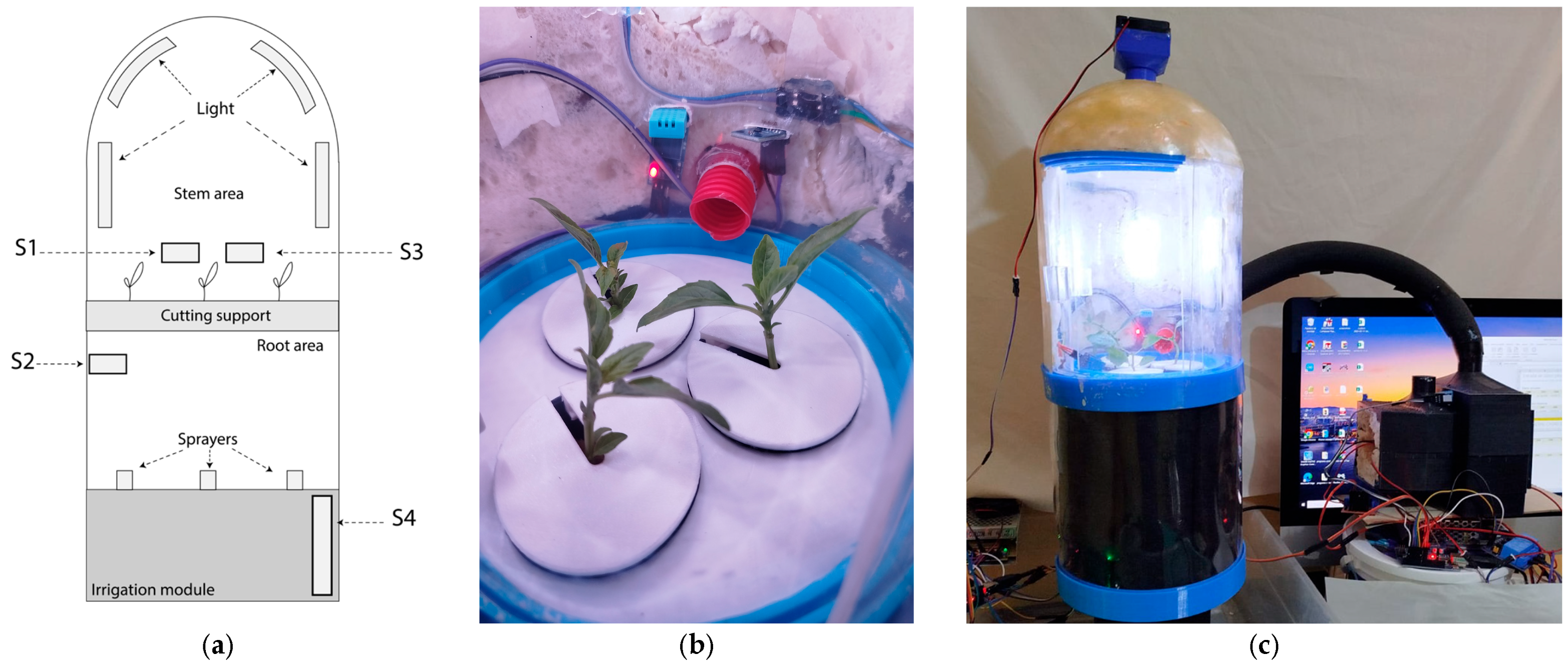
Based on a block diagram (a) (see
Figure 8) and the modular configuration overview (see
Figure 9), a physical implementation of the conceptual design was carried out. Two functional tests were conducted to verify the operation of the main components that comprise the prototype’s modular system.
The physical implementation corresponding to the aeroponic variant was assembled using the modular layout illustrated in
Figure 8 and
Figure 9.
Figure A1 presents a visual overview of the constructed prototype. Panel (a) shows the schematic arrangement of sensors within the system, distributed across the stem zone, rooting zone, and irrigation module. Panel (b) captures the interior of the chamber, where the lavender cuttings were housed during the functional tests. Panel (c) provides a general perspective of the full assembly, including lighting, irrigation, and electronic control subsystems.
Four sensors were installed to monitor key environmental variables: S1 measured temperature and humidity in the stem zone; S2 measured temperature and humidity in the root area; S3 measured light intensity near the cuttings; S4 measured the pH level in the irrigation reservoir.
These sensors enabled a detailed assessment of environmental conditions during each functional test.
Figure A1.
(a) Overview of the sensor positions within the physical implementation of the aeroponic variant: S1—temperature and humidity sensor (stem zone); S2—temperature and humidity sensor (root zone); S3—light sensor; S4—pH sensor. (b) Photograph of the stem area with three basil cuttings; (c) general view of the assembled prototype under test conditions.
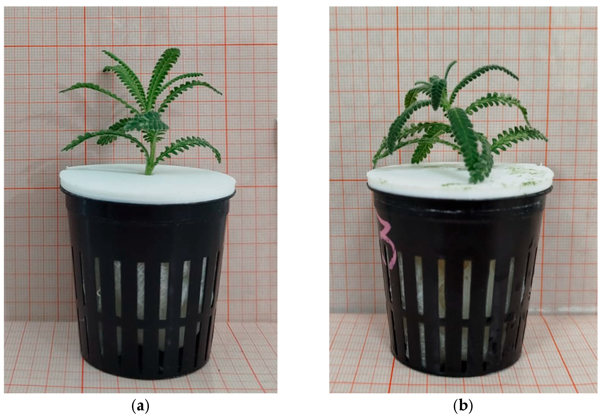
Appendix B.1. First Test—Lavender Cuttings
The first test was conducted from 24 January to 8 February. A total of three lavender cuttings were introduced into the growth chamber, each measuring between 45 and 56 mm in length. The cuttings were placed in small net pots that served as structural supports within the aeroponic system. Irrigation was carried out using water only, applied twice daily (see
Table A7), and continuous artificial lighting was provided via LEDs throughout the 15-day testing period.
Figure A2.
One of the three lavender cuttings used in this test: panel (a) illustrates its appearance at the beginning of the experiment, while panel (b) depicts its condition on the 15th and final day of growth.
Figure A2.
One of the three lavender cuttings used in this test: panel (a) illustrates its appearance at the beginning of the experiment, while panel (b) depicts its condition on the 15th and final day of growth.
Sensors were installed to monitor environmental variables, including temperature and humidity in both the root and stem zones. A light sensor was positioned at the stem level, and a pH sensor was placed in the water tank of the irrigation module. Notably, the air conditioning module was not yet operational during this test. Environmental data collected during the period are presented in
Table A3.
Table A3.
Environmental parameters recorded in Test 1 (lavender cuttings).
Table A3.
Environmental parameters recorded in Test 1 (lavender cuttings).
| Parameter | Min | Max | Average |
|---|
| Temperature in root zone (°C) | 20 | 29 | 25 |
| Temperature in stem zone (°C) | 16 | 28 | 21.98 |
| Humidity in root area zone (%) | 6 | 99 | 52.7 |
| Humidity in the stem zone (%) | 0 | 56 | 31.7 |
| Light intensity (lux) | 195 | 367.67 | 283 |
| pH (in irrigation tank) | 0.10 | 17.48 | 13.14 |
Growth measurements were obtained before and after the test, as shown in
Table A4.
Table A4.
Growth parameters of lavender cuttings (Test 1).
Table A4.
Growth parameters of lavender cuttings (Test 1).
| Parameter | Min (mm) | Max (mm) | Average (mm) |
|---|
| Stem length before test | 45 | 56 | 51.3 |
| Stem width before test | 48 | 59 | 54 |
| Stem length after test | 28 | 56 | 43 |
| Stem width after test | 30 | 60 | 48.33 |
| Root length | 0 | 41 | 13.66 |
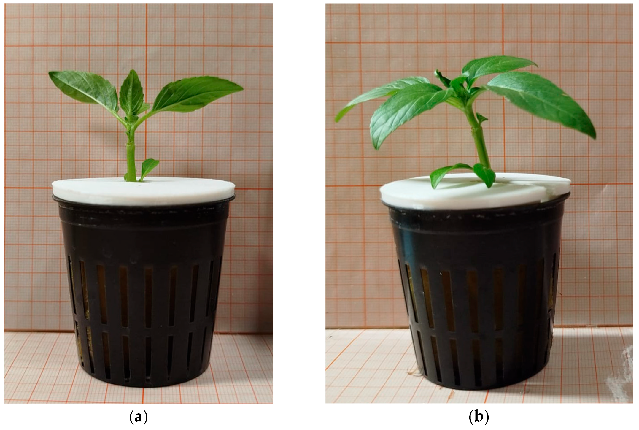
Appendix B.2. Second Test Basil Cuttings
A second functional test was conducted from 7 April to 21 April using three basil cuttings, each measuring approximately 86–87 mm in length (see
Figure A3). As in the previous test, the system operated under continuous LED lighting and used aeroponic irrigation with clean water, this time applied three times a day (see
Table A7). The key difference in this trial was the implementation of the air conditioning module, which successfully maintained internal temperatures between 20 °C and 27 °C throughout the testing period.
Environmental conditions during this test, such as temperature, humidity, pH levels, and light intensity, were monitored using the sensor layout described previously (see
Figure A1a). The recorded values are presented in
Table A5. Additionally, the growth performance of the basil cuttings was monitored through photographic and biometric indicators. The comparative measurements from day 1 and day 15 are shown in
Table A6, highlighting noticeable improvements in stem elongation and foliage development.
Figure A3.
One of the three basil cuttings used in this test: panel (a) illustrates its appearance at the beginning of the experiment, while panel (b) depicts its condition on the 15th and final day of growth.
Figure A3.
One of the three basil cuttings used in this test: panel (a) illustrates its appearance at the beginning of the experiment, while panel (b) depicts its condition on the 15th and final day of growth.
Table A5.
Environmental parameters recorded in Test 2 (basil cuttings).
Table A5.
Environmental parameters recorded in Test 2 (basil cuttings).
| Parameter | Min | Max | Average |
|---|
| Temperature in root zone (°C) | 20 | 28 | 23.76 |
| Temperature in stem zone (°C) | 20 | 28 | 23.6 |
| Humidity in root area zone (%) | 8 | 98 | 59.25 |
| Humidity in the stem zone (%) | 8 | 93 | 40 |
| Light intensity (lux) | 132.5 | 622.5 | 241.73 |
| pH (in irrigation tank) | 10.19 | 16.46 | 12.78 |
Table A6.
Growth parameters of basil cuttings (Test 2).
Table A6.
Growth parameters of basil cuttings (Test 2).
| Parameter | Min (mm) | Max (mm) | Average (mm) |
|---|
| Stem length before test | 86 | 87 | 86.3 |
| Stem width before test | 45 | 93 | 69 |
| Stem length after test | 92 | 98 | 95 |
| Stem width after test | 68 | 117 | 89.66 |
| Root length | 37 | 38 | 37.33 |
Appendix B.3. Irrigation Schedules
The irrigation schedules applied during the two tests are summarized in
Table A7. Both tests employed an aeroponic system with clean water, but the frequency and timing of irrigation differed. In Test 1, irrigation occurred twice daily, while in Test 2, a three-period schedule was implemented to enhance water distribution and environmental control.
Table A7.
Irrigation type and schedule for both tests.
Table A7.
Irrigation type and schedule for both tests.
| Test | Irrigation Type | No. of Periods | Irrigation Times |
|---|
| Test 1 | Aeroponic | 2 | 09:00–09:05; 21:00–21:05 |
| Test 2 | Aeroponic | 3 | 08:00–08:03; 16:00–16:03; 00:00–00:03 |
Appendix B.4. Success Rate
The success of each functional test was defined by the appearance of visible roots in the cuttings at the end of the 15-day period. As shown in
Table A8, both tests yielded different success rates: the first test resulted in only partial rooting, while the second achieved full rooting in all cuttings. However, we emphasize that these tests were conducted solely to verify the correct functioning of the prototype’s modular components under real operating conditions. A more rigorous experimental protocol, including larger sample sizes and comparative analyses, is under development and will be published in a forthcoming technical note.
Table A8.
Rooting success rate in both tests.
Table A8.
Rooting success rate in both tests.
| Number of Tests | Cuttings Placed | Cuttings Collected | Cuttings with Root Growth | Success Rate |
|---|
| Test 1 | 3 | 2 | 1 | 33.3% |
| Test 2 | 3 | 3 | 3 | 100% |
References
- Ali, A. Hydroponics, Aeroponics an Aquaponic as Compared with Conventional Farming. Am. Sci. Res. J. Eng. Technol. Sci. 2017, 27, 247–255. [Google Scholar]
- Pomoni, D.I.; Koukou, M.K.; Vrachopoulos, M.G.; Vasiliadis, L. A Review of Hydroponics and Conventional Agriculture Based on Energy and Water Consumption, Environmental Impact, and Land Use. Energies 2023, 16, 1690. [Google Scholar] [CrossRef]
- FAO. Coping with Water Scarcity an Action Framework for Agriculture and Food Security; FAO Water Reports; FAO: Rome, Italy, 2012. [Google Scholar]
- Gopinath, P.; Vethamoni, P.I.; Gomathi, M. Aeroponics Soilless Cultivation System for Vegetable Crops. Chem. Rev. Lett. 2017, 6, 838–849. [Google Scholar]
- Mitchell, C.A. History of Controlled Environment Horticulture: Indoor Farming and Its Key Technologies. HortScience 2022, 57, 247–256. [Google Scholar] [CrossRef]
- Macwan, J.; Pandya, D.; Pandya, D.H.; Mankad, D.A. Review on Soilless Method of Cultivation: Hydroponics. Int. J. Recent Sci. Res. 2020, 11, 37122–37127. [Google Scholar]
- Weiss-Technik. Available online: https://weiss-technik.mx/product/camaras-modulares-de-crecimiento-de-plantas-fitotron-hgc/ (accessed on 15 April 2025).
- Conviron.com. Available online: https://www.conviron.com/ (accessed on 18 April 2024).
- Environment Growth Chambers. Available online: https://www.egc.com (accessed on 20 April 2024).
- Bua, C.; Adami, D.; Giordano, S. GymHydro: An Innovative Modular Small-Scale Smart Agriculture System for Hydroponic Greenhouses. Electronics 2024, 13, 1366. [Google Scholar] [CrossRef]
- Patel, K.; Chauhan, D.; Mishra, P.; Rath, J.J.; Saxena, K.K.; Prasad, K.S.R.; Bandhu, D. Design and development of a modular hydroponic tower with topology optimization. Int. J. Interact. Des. Manuf. (IJIDeM) 2024, 19, 4243–4252. [Google Scholar] [CrossRef]
- Fue, K.G.; Porter, W.M.; Barnes, E.M.; Rains, G.C. An Extensive Review of Mobile Agricultural Robotics for Field Operations: Focus on Cotton Harvesting. Agriengineering 2020, 2, 150–174. [Google Scholar] [CrossRef]
- Nikolov, N.V.; Atanasov, A.Z.; Evstatiev, B.I.; Vladut, V.N.; Biris, S.-S. Design of a Small-Scale Hydroponic System for Indoor Farming of Leafy Vegetables. Agriculture 2023, 13, 1191. [Google Scholar] [CrossRef]
- Wright, H.; Moschopoulos, A.; Fountain, L. Design of low cost, open-source prototype plant growth chambers for evaluating crop suitability for space environments. Acta Hortic. 2023, 1369, 141–148. [Google Scholar] [CrossRef]
- Simpson, T.W.; Maier, J.R.; Mistree, F. Product platform design: Method and application. Res. Eng. Des. 2001, 13, 2–22. [Google Scholar] [CrossRef]
- Ulrich, K.T.; Eppinger, S.D. Product Design and Development, 5th ed.; The McGraw-Hill Companies: New York, NY, USA, 2012; pp. 183–206. [Google Scholar]
- Stone, R.B.; Wood, K.L. Development of a Functional Basis for Design. J. Mech. Des. 1999, 122, 359–370. [Google Scholar] [CrossRef]
- Camburn, B.; Wood, K. Principles of maker and DIY fabrication: Enabling design prototypes at low cost. Des. Stud. 2018, 58, 63–88. [Google Scholar] [CrossRef]
- Camburn, B.; Viswanathan, V.; Linsey, J.; Anderson, D.; Jensen, D.; Crawford, R.; Otto, K.; Wood, K. Design prototyping methods: State of the art in strategies, techniques, and guidelines. Des. Sci. 2017, 3, e13. [Google Scholar] [CrossRef]
- Suñer, L.A. Estudio de los Métodos de Diseño Modular y sus Aplicaciones. Master’s Thesis, Universidad de Zaragoza, Zaragoza, Spain, 2017. [Google Scholar]
- Hölttä, k.; Tang, V.; Seering, W.P. Modularizing product architectures using dendrograms. In Proceeding of the ICED 03, the 14th International Conference on Engineering Design, Iced, Stockholm, Sweden, 19–21 August 2003. [Google Scholar]
- Stone, R.B.; Kurtadikar, R.; Villanueva, N.; Arnold, C.B. A customer needs motivated conceptual design methodology for product portfolio planning. J. Eng. Des. 2008, 19, 489–514. [Google Scholar] [CrossRef]
- Cross, N. Métodos de Diseño, Estrategias para el Diseño de Producto; Limusa: Mexico City, Mexico, 2002; pp. 43–57. [Google Scholar]
- Honary, H.; Vasundhara, M.; Nuthan, D. Hydroponics and Aeroponics as Alternative Production Systems for High-Value Medicinal and Aromatic Crops: Present Scenario and Future Prospects. J. Med. Aromat. Plants 2011, 33, 397–403. [Google Scholar]
- Cambridge Dictionary. Available online: https://dictionary.cambridge.org/dictionary/english/ad-hoc (accessed on 22 April 2025).
- Otto, K.N.; Wood, K.L. Product Design: Techniques in Reverse Engineering and New Product Development; Pearson Education: Upper Saddle River, NJ, USA, 2001. [Google Scholar]
- Meyer, M.H.; Lehnerd, A.P. The Power of Product Platforms, 1st ed.; The Free Press: New York, NY, USA, 1997. [Google Scholar]
- Ulrich, K. The role of product architecture in the manufacturing firm. Res. Policy 1995, 24, 419–440. [Google Scholar] [CrossRef]
- FarmBot Inc. Available online: https://farm.bot/ (accessed on 27 June 2025).
- Harper, C.; Siller, M. OpenAG: A Globally Distributed Network of Food Computing. IEEE Pervasive Comput. 2015, 14, 24–27. [Google Scholar] [CrossRef]
- Ferrer, E.C.; Rye, J.; Brander, G.; Savas, T.; Chambers, D.; England, H.; Harper, C. Personal Food Computer: A New Device for Controlled-Environment Agriculture. In Proceeding of the Future Technologies Conference (FTC) 2018; Springer: Cham, Switzerland, 2019; Volume 881, pp. 1077–1096. [Google Scholar]
- Stone, R.B.; Wood, K.L.; Crawford, R.H. A heuristic method for identifying modules for product architectures. Des. Stud. 2000, 21, 5–31. [Google Scholar] [CrossRef]
- Nielsen, J. Usability Engineering, 1st ed.; Morgan Kaufmann: San Francisco, CA, USA, 1994. [Google Scholar]
- Blessing, L.T.M.; Chakrabarti, A. DRM, A Design Research Methodology, 1st ed.; Springer: London, UK, 2009. [Google Scholar]
- Pahl, G.; Beitz, W. Engineering Design a Systematic Approach, 3rd ed.; Springer: London, UK, 2007. [Google Scholar]
- Six Sigma. Unlocking Innovative Solutions with TRIZ: A Powerful Problem-Solving Methodology. Available online: https://www.6sigma.us/six-sigma-in-focus/triz-inventive-problem-solving-methodology/ (accessed on 15 March 2025).
- Guo, F.; Gershenson, J.K. Discovering relationships between modularity and cost. J. Intell. Manuf. 2007, 18, 143–157. [Google Scholar] [CrossRef]
- Zhang, Y.; Gershenson, J.K. An Initial Study of Direct Relationships between Life-Cycle Modularity and Life-Cycle Cost. Concurr. Eng. Res. Appl. 2003, 11, 121–128. [Google Scholar] [CrossRef]
- Montoya, A.P.; Obando, F.A.; Morales, J.G.; Vargas, G. Automatic Aeroponic Irrigation System Base dom Arduino’s Platform. J. Phys. Conf. Ser. 2017, 850, 012003. [Google Scholar]
- Garzón, J.; Montes, L.; Garzón, J.; Lampropoulos, G. Systematic Review of Technology in Aeroponics: Introducing the Technology Adoption and Integration in Sustainable Agriculture Model. Agronomy 2023, 13, 2517. [Google Scholar] [CrossRef]
Figure 1.
Visual representation of the transition from conventional agriculture to modular growth chambers through controlled environment techniques. The figure highlights the limitations of traditional practices, the promise of controlled systems, and the role of modular design in increasing accessibility and reducing costs.
Figure 2.
Distribution of user needs by frequency (X-axis) and importance weight (Y-axis), highlighting base and differentiating requirements.
Figure 2.
Distribution of user needs by frequency (X-axis) and importance weight (Y-axis), highlighting base and differentiating requirements.
Figure 3.
Black box model of the growth chamber.
Figure 3.
Black box model of the growth chamber.
Figure 4.
Complete base functional model of the modular growth platform. The diagram integrates all the primary functions derived from the needs analysis. It illustrates the system’s inputs (energy, water, and signals), functional transformations (such as heating, lighting, and actuation), and outputs (rooted cuttings, environmental data). This visual model also highlights potential module boundaries and interface points, providing the foundation for subsequent modular architecture decisions.
Figure 5.
Identification of modules via heuristics in the functional model of variant 1 (aeroponic system). Colored dashed lines represent module boundaries identified through architectural heuristics: (a) irrigation module; (b) electricity supply module; (c) cutting growth area; (d) air conditioning module; (e.1) pump water module; (e.2) heating module; (e.3) light module; (f.2) to (f.6) monitoring components; and (f.1) and (f.7) components requiring electricity. Bifurcation in the growth area is represented by (g.1) and (g.2).
Figure 6.
Identification of modules using heuristics in the functional model of variant 2 (drip system). The diagram highlights module boundaries identified through architectural heuristic by colored dashed lines: (a) irrigation module; (b) electricity supply module; (c) cutting growth area; (d) air conditioning module; (e.1) pump water module; (e.2) heating module; (e.3) light module; (f.2) to (f.6) monitoring components; and (f.1) and (f.7) components requiring electricity. The physical bifurcation of the growth area is represented by (g.1) and (g.2).
Figure 7.
Identification of modules via heuristics in the functional base model: (a) irrigation module; (b) electricity supply module; (c) cutting growth area; (d) air conditioning module; (e.1) pump water module; (e.2) heating module; (e.3) light module; (f.2) to (f.4) monitoring components; (f.1) and (f.5) components requiring electricity; (g.1) and (g.2) bifurcation of the growth area.
Figure 8.
Block diagram based on the functional model of variant 1 (aeroponic system). The illustration displays the proposed spatial configuration of modules within the chamber architecture. The diagram emphasizes the flows of signal (black), energy (yellow), and water (green), as well as the stacking logic of modular subsystems (cutting support, irrigation, environmental control). It also details the assignment of sensors and actuators to each functional zone. This representation supports spatial planning and interface coordination for future CAD modeling and physical prototyping.
Figure 9.
Block diagram, a second configuration derived from the functional model of variant 1 (aeroponic system). This layout illustrates a rearrangement of the modules to explore alternative spatial distributions. The irrigation, lighting, and air conditioning modules remain functionally equivalent to those of the original configuration, while the growth areas and control elements are repositioned to enhance modular substitution and improve internal flow routing. The representation underscores the adaptability of the system’s platform-based architectures.
Figure 10.
Overview of the functional modular structure showing the main system modules, their interactions, and the reconfigurable layout that enables experimental adaptation and modular scalability. The solid lines represent the connections between monitoring components (sensors) and the database. On the other hand, the dotted lines identify individual modules within the structure.
| Disclaimer/Publisher’s Note: The statements, opinions and data contained in all publications are solely those of the individual author(s) and contributor(s) and not of MDPI and/or the editor(s). MDPI and/or the editor(s) disclaim responsibility for any injury to people or property resulting from any ideas, methods, instructions or products referred to in the content. |
© 2025 by the authors. Licensee MDPI, Basel, Switzerland. This article is an open access article distributed under the terms and conditions of the Creative Commons Attribution (CC BY) license (https://creativecommons.org/licenses/by/4.0/).


 ,
, 


