Article

Mechanical Properties of 17-4 PH Stainless Steel Manufactured by Atomic Diffusion Additive Manufacturing

by
Animesh Kumar Basak
1,*,
Jasim Mohammed Sali
2 and
Alokesh Pramanik
2,*
1
Adelaide Microscopy, The University of Adelaide, Adelaide, SA 5005, Australia
2
School of Civil and Mechanical Engineering, Curtin University, Bentley, WA 6102, Australia
*
Authors to whom correspondence should be addressed.
Designs 2025, 9(3), 66; https://doi.org/10.3390/designs9030066
Submission received: 27 April 2025 / Revised: 20 May 2025 / Accepted: 23 May 2025 / Published: 28 May 2025
(This article belongs to the Special Issue Post-manufacturing Testing and Characterization of Materials)

Abstract

Atomic diffusion additive manufacturing (ADAM) is a specialized extrusion-based metal additive manufacturing (MAM) process where metal parts are produced through a three-stage process of printing, de-binding and sintering. Several scientific facts, such as dimensional error, surface quality, tensile behavior and the internal structure of this process for specific materials for certain conditions, are not well explained in the existing literature. To address these issues, the present manuscript investigates the effect of infill type and shell thickness on 17-4 precipitation-hardened (PH) stainless steels on the dimensional accuracy, surface roughness and mechanical properties of the printed specimens. It was found that the strength (maximum ultimate tensile strength up to 1049.1 MPa) and hardness (290 HRB) of the specimens mainly depend on shell thickness, while infill type plays a relatively minor role. The principle of atomic diffusion may be the reason behind this pattern, as an increase in shell thickness is essentially an increase in the density of material deposited during printing, allowing more fusion during sintering and thus increasing its strength. The two different infill types (triangular and gyroid) contribute towards minimal changes, although it should be noted that triangular specimens exhibited greater ultimate tensile strength, whereas the gyroid had slightly longer elongation at break. Dimensional accuracy and surface roughness for all the specimens remain reasonably consistent. The cross-section of the tensile tested specimens revealed significant pores in the microstructure that could contribute to a reduction in the mechanical properties of the specimens.

1. Introduction

Stainless steel (SS) is one of the most important structural materials used in different sectors like industrial machineries, automotive, household and so on. Stainless steel has immense tensile (up to 579 MPa for SS316L) and yield strength (up to 310 MPa for SS316L), as well as ductility (up to 70%) [1]. In many industries, 17-4 precipitation-hardened (PH) stainless steel is utilized for its corrosion resistance and high mechanical strength. Though its wear resistance is lower than that of hard coatings [2], its combined corrosion–wear resistance [3] is superior. Applications of 17–4 PH stainless steel include those in the marine, chemical and power-generating sectors [4]. From start to finish, the manufacturing of steels consists of various techniques, starting from ingot-making by casting. After that, various subtractive manufacturing processes are employed that lead to steel wastage (saw dust, chips and off-cuts), increasing the final product costs. This calls for additional steps to clean up and dispose of the waste appropriately. In that respect, ‘additive manufacturing (AM)’ opens up new avenues for the production of net/near-net-shaped components, which not only minimizes such waste of materials but also delivers high-quality parts [5].
Atomic diffusion additive manufacturing (ADAM) [6] is a three-stage extrusion-based metal additive manufacturing (MAM) [7] process with the traits of higher accuracy, complicated geometry formation, design flexibility, material savings and personalization while keeping product costs to a low level. In contrast to traditional subtractive manufacturing (e.g., cutting, drilling, grinding and machining), this process involves iteratively adding materials layer upon layer [8]. Extrusion-based MAM techniques are viable alternatives to subtractive manufacturing, since the equipment is less expensive, and no loose powders or lasers are utilized during the production process [9]. The formation of a powder–binder blend is the first step in this manufacturing process. The next step is the printing, where the mixture is subsequently pushed through a nozzle, which relies on the Fused Deposition Modelling (FDM) concept to deposit material layer by layer and form a 3D object. To create the dense metallic components, debinding and sintering are required in the post-printing process [10]. Dense, additively manufactured metal parts offer equal/better quality than that of conventionally manufactured counterparts by controlling their porosity and microstructure [11]. Crack propagation can be mitigated by limiting the porosity of the material, which can be accomplished by controlling the applied energy volume and quality of the feedstock [12]. The finer microstructure in additively manufactured materials generally increase their ultimate and yield strengths [13]. The build orientation also has an impact on the strength of the material, where a tensile stress in one direction will be able to resist a higher load than stress in the other direction [14] and thus give rise to anisotropy in the as-built components [15].
In the experiment carried out by Gabilondo et al. [10], the influence of specimen print orientation was explored. Through tensile testing, it was found that the horizontally printed specimens were much stronger (530 MPa) than the vertically printed specimens (370 MPa). Under examination, it was also found that the porosity of the horizontal specimens (5.67%) was lower than that of the vertical specimens (6.56%). It was also established that the horizontal samples had lines along the axial direction, causing any cracks that propagated to reach the end more easily. Another study conducted by Chacón et al. [16] showed the same trend, where 3D-printed samples show anisotropic behavior. Lower mechanical properties of the samples were observed when printed upright, whereas flat/horizontal samples had much higher strength and stiffness. A build orientation parallel to infill lines will stop the cracks from propagating, whereas in perpendicular printed specimens, infill lines will easily allow cracks to propagate. Burgess et al. [17] found great variation between specimens printed vertically and horizontally in terms of mechanical properties. A MarkForged metal XTM unit was employed to print the specimens on varying axis and angles, as well as a vertical free-standing specimen. The staircase effect [18] was dominant in specimens printed at an angle other than 0° or 90°. Theoretically, the sintering process should eliminate any reason for variation in mechanical properties for specimens printed at different orientations, as the fusion occurs between metal stands in the furnace. Strength should be increased regardless of specimen print orientation; however, this was not the case, as reported in the literature [19]. Henry et al. [1] also came to a similar conclusion after testing a MarkForged Metal X printed specimen, printing at varying print directions. Samples printed with the shell layers oriented perpendicular to the loading direction during tensile testing resulted in poor mechanical properties compared to samples printed with shell layers oriented parallel to the loading direction. Sambrook et al. [20] carried out experiments on 17-4 PH stainless steel printed by a MarkForged Metal X printer to print with horizontal and vertical print directions. According to their reports, horizontally printed specimens performed 14.7% better in Young’s modulus, 64% greater in yield strength and 84.5% greater in ultimate tensile strength, with an increase of 67.1% in elongation at break when compared to vertically printed specimens under the same printing parameters.
Rosnitschek et al. [21] conducted a study on 316L stainless steel manufactured additively by a Desktop Metal Studio printer. The focus was on infill degree and a hexagonal infill pattern with four different infill densities. It was found that 75% and 50% infill patterns provided the strongest specimens, while the 25% infill specimen performed worse than those two in terms of Young’s modulus and tensile stress. It was surprising to note that the 100% infill specimen performed worse than the 50% and 75% specimens. Rosnitschek et al. [21] believed that this occurred due to the presence of printing flaws, as well as thermal stress build-up owing to the deposition of a large quantity of material, which hampered the components’ homogeneous cooling. Thawon et al. [22] tensile tested 316L and 17-4 PH stainless steel at different infill densities to determine their mechanical behavior. The testing found the 316L specimens to be of ductile nature, whereas the 17-4 PH specimens were of brittle nature, with higher yield strength both in the elastic region and over the whole strain dimension. In addition, there was a significant increase in the mechanical properties of the material with an increase in infill densities. The non-solid specimens had a linear increase in mechanical properties, whereas the solid specimen (100% infill) had an exponential increase in mechanical properties. Gabilondo et al. [10] investigated the hardness of 316L stainless steel specimens fabricated at varying infill patterns and orientations by the Bound Metal Deposition (BMD) [23] process. They reported an average hardness of 120 HV, which was significantly lower than that of the same specimens fabricated by either Powder Bed Fusion (PBF), 230–280 HV or traditional casting, 165 HV. This was due to the existence of pores, voids and intergranular porosity in the BMD specimens. The low cooling during sintering was a suspected reason that may have contributed to that.
Godec et al. [24] investigated the layer thickness, extrusion temperature and flow rate multiplier of 17-4 PH stainless steel manufactured by Fused Filament Fabrication (FFF). It was found that the layer thickness had a direct correlation with the tensile strength. A larger layer thickness requires fewer layers for the part to be printed; this, in turn, allows for less area for voids to form and creates an area of weak spots in the specimen. The decrease in the interlayer area will allow for a stronger tensile output, as less of the part’s strength is reliant on the fusion between layers. Similar results were also reported by Shakeri et al. [25], where a large layer height results in more deformation and geometrical inaccuracies. There are many more investigations on the properties of atomic diffusion additive manufactured 17-4 PH. Raju et al. [26] investigated the printability of holes at different orientations and explored the properties of the green samples with SEM and CT scan. Rodriguez et al. [27] investigated the effect of printing orientation on density, surface roughness, hardness, tensile properties and fatigue behavior. Bouaziz et al. [28] explored the effect of layer thickness on microstructural pattern during tensile testing. They [29] also investigated the effect of heat treatment on the surface roughness and tensile strength.
Because it is a relatively new technique, it is clear from above discussion that there is no investigation on the effect of wide range printing parameters such as shell thickness and infill type on dimensional accuracy, roughness and tensile behavior. However, this is imperatively needed to exploit the potential of ADAM for customized design and implementation to develop advanced products. To address this issue, this research aims to investigate the fabrication parameters shell thickness and infill type, which have not been explored yet. In this respect, the effect of shell thickness and infill type on dimensional accuracy, mass/density, surface roughness and mechanical properties were explored. In addition to that, the microscopic structure of the specimens was investigated after tensile testing, and the obtained mechanical properties were compared to those of traditionally manufactured (wrought) specimens.

2. Materials and Methodology

2.1. Material

In 17-4 PH stainless steel (17-4PH SS), a well-known class of stainless steel, the hardening effect takes place due the martensitic precipitation. The 17–4PH SS powder is blended with wax and polymeric binder to give it a wire form and spooled in a coil. This was commercially acquired from the manufacturer (Desktop Metal Inc., Burlington, MA, USA). The metal powder composition (% wt.) was 0.07% C, 15.5–17.5% Cr, 3–5% Ni, 3–5% Cu, 1.0% Mn and 0.15–0.45% (Nb and Ta). The relatively high copper content provided the necessary precipitation towards the strengthening of this alloy [30].

2.2. Specimen Size

The specimen was a sub sized, ‘dog-bone’ shaped tensile testing specimen, following the code of ASTM E8/E8M [31]. ‘Autodesk Inventor’ software (Version 1.1) was used to draw the specimen in 3D format and export it as an STL file, which was readable by ‘MarkForged’ proprietary slicing software called ‘Eiger’. ‘Eiger’ imported the CAD software and allow for calculations of all input parameters for the specimen to be fabricated. All settings were left at default, to permit the software to determine the optimum print settings, except shell thickness and infill pattern. The software provides a layer-by-layer breakdown of the printing process and the details of the infill for each part.

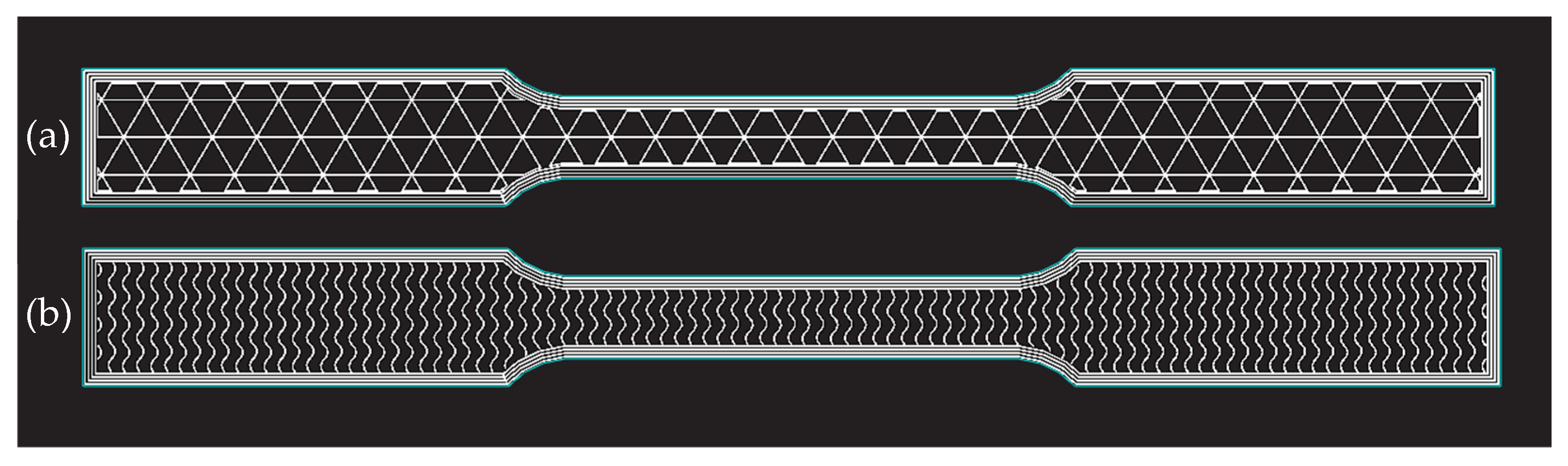
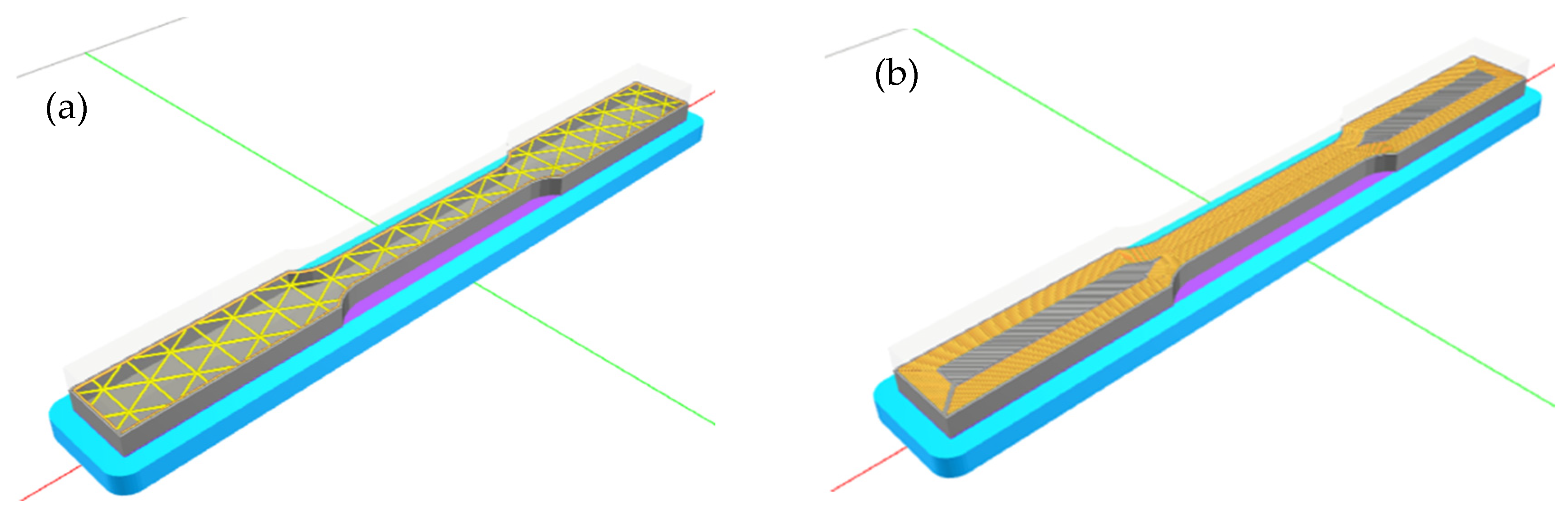
2.3. Input Parameters

In this research, the variable input parameters were infill type and shell thickness (top/bottom and walls). Two different infill types, namely, triangular and gyroid, were explored in this research. Figure 1 shows a comparison of gyroid and triangular infill types. The infill type dictates the structure of the internal pattern of the print inside the wall layers. Different infill structures require a different amount of material and time to create, therefore allowing for appropriate conclusions to be drawn regarding each infill’s effect on the respective mechanical properties. Together with that, four different shell thicknesses were also explored, namely, 0.5, 1, 1.5 and 2 mm. Shell thickness refers to the thickness of the solid wall and top/bottom layers. Previous research conducted in-depth studies on layer thickness, but overall shell thickness was neglected; therefore, it was considered in this study. Figure 2 shows a comparison of shell thickness between two specimens.
Eight (8) unique 17-4 PH stainless-steel specimens were printed, each with varying attributes, as listed in Table 1. Each specimen was triplicated for tensile testing; thus, the total printed specimen number was 24.

2.4. ADAM Process

The fabrication of the specimens incorporates three stages: ‘printing’, ‘debinding’ and ‘sintering’, before generating a final specimen. The filaments in wire form sat above the print bed. Before the start of a new print, the print bed was levelled; this ensured the initial layer of print was completed correctly, as it was a base for the rest of the parts. The Eiger slicing software connected with the printer, activating the printing process, which was then carried out over a time period defined by the input parameters for component composition and geometry. The printer was the commercially available MarkForged metal XTM. Initially, a base plate known as a raft was printed onto the print bed, and then the ceramic binder was deposited before the initiation of the required specimen. The ceramic binder allows for sufficient strength during printing, debinding and sintering to hold the specimen in place on the print bed, while also allowing easy separation after sintering was complete to detach the specimen from the raft. Once printing was complete, the part was known as a ‘green’ part.
Printed specimens were placed into the stainless-steel basket before being lowered into the debinder unit. During this process, the binder that held together the metal particles dissolved, creating an ‘open-pore’ network. Once debinding was completed, the part was known as a ‘brown’ part.
The furnace was the location where ‘atomic diffusion’ occurs, fusing the metal particles together at elevated temperature to introduce strength and increase the mechanical properties of the printed specimen. The sintering time was around 24–30 h and constantly monitored. The maximum temperature achievable in the furnace was 1300 °C, which was below the melting point of printed materials (17-4 PH SS). Once the specimen was removed from the furnace, the rafts were easily removed by hand. The specimen, now called the ‘white’ part. could be used for its designed use or post-processing to further improve its physical and mechanical properties.

2.5. Measurement Instruments

The dimensional accuracy of the printed specimens was determined using a coordinate measuring machine (CMM) named Sheffield Discovery II D-8 CMM (Discovery II, manufactured by Sheffield, UK) accompanied by a diamond probe. This CMM was also used to measure the gauge thickness, gauge width, cylindricity at radii and warping of the specimen. The Mitutoyo SJ-201 surface roughness testing machine (Surftest Sj-210P, Mitutoyo, Tokyo, Japan) was used to measure surface roughness. A cut-off length of 25 mm was used. The hardness test used for this experiment was conducted using a Wilson 4JRa machine. Hardness results were recorded in HRB, three readings were taken per sample, and the data were averaged to increase reliability. The Shimadzu AGSX-300 (Shimadzu Autograph, Tokyo, Japan) was used to evaluate the tensile behavior of each specimen. The selected load cell was 300 kN, which was adequate for breaking steel and alloy specimens. A constant elongation rate of 1 mm/s was used on all specimens at ambient temperature (24 °C). The Olympus BX51M microscope (Olympus corporation, Tokyo, Japan) paired with Olympus stream motion software was used for optical microscopic evaluation of the specimens. The fractured tensile specimens were further examined by a field emission scanning electron microscope (FE-SEM), model Quanta 450 SEM (Thermofisher scientific, Waltham, MA, USA). The Archimedes principle was used to measure the density. A scale accurate to 2 decimal places, a beaker of demineralized water and a suspension stand with a piece of string for the specimen were used to measure the density of the specimen. The specimen was weighed in air, then subsequently attached to the string and weighed in water; the displacement of water was the weight taken as the buoyant force. Once the mass of displaced water was recorded, the density could be calculated.

3. Results and Discussion

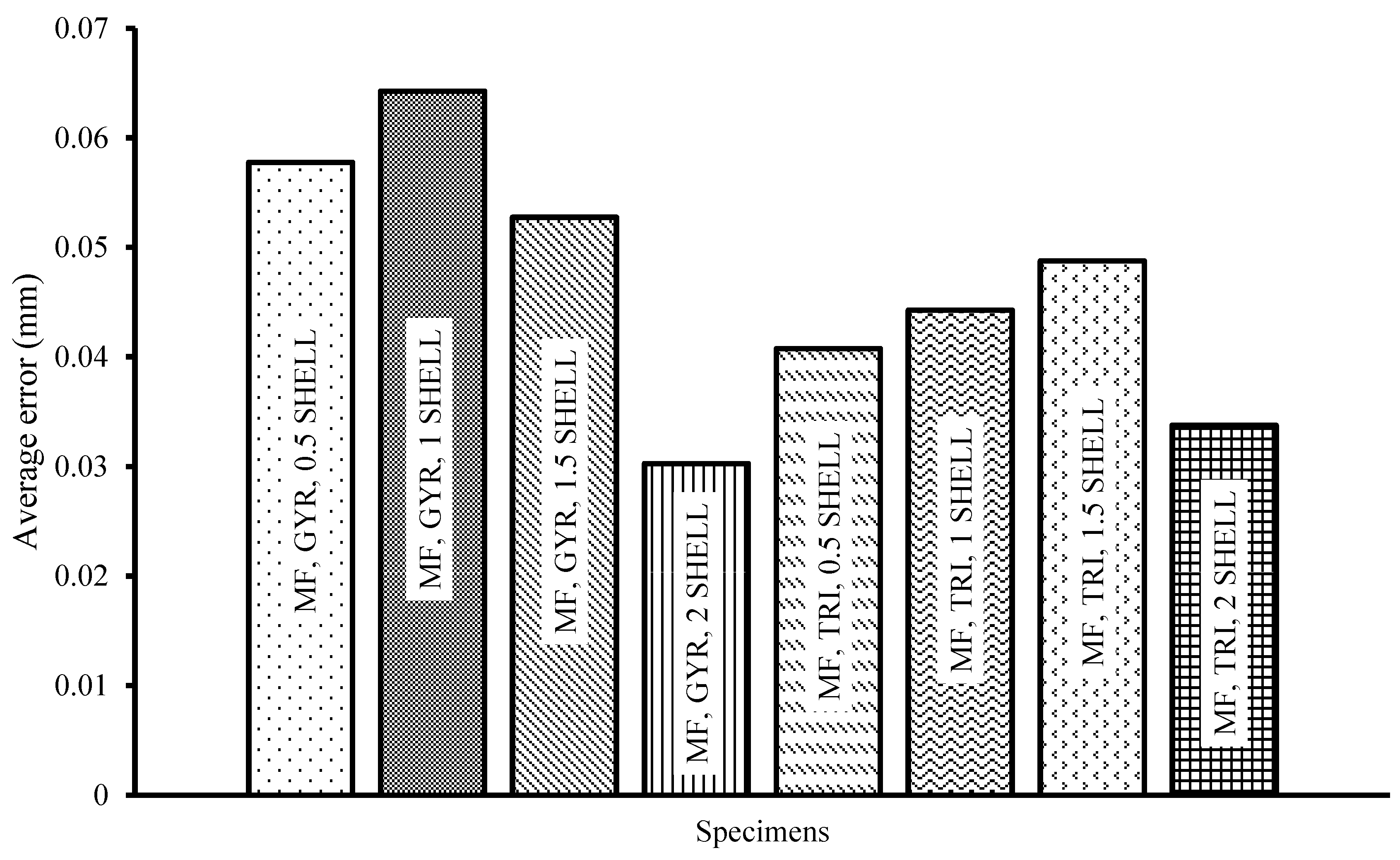
3.1. Dimensional Accuracy

To access the dimensional accuracy of the printed specimens, four important measurements were taken, namely, cylindricity of gauge radius, height, perpendicularity and the overall length of the specimen. These were taken for every specimen printed after sintering.

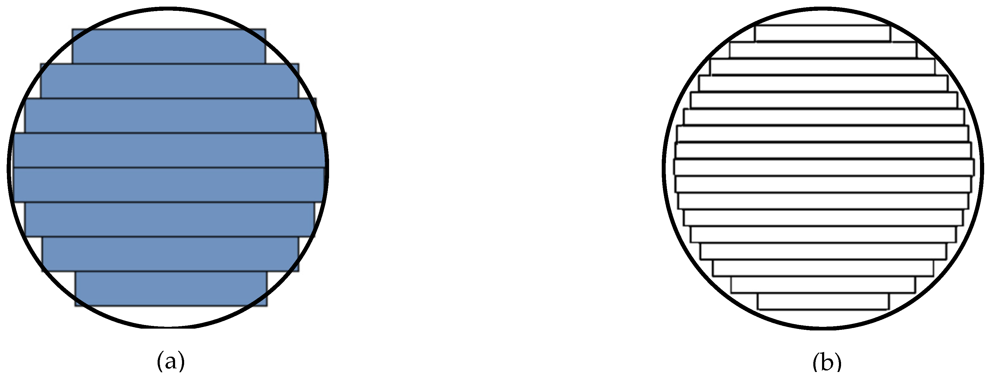
3.1.1. Cylindricity Error at Gauge Radius

Figure 3 showed the average cylindricity error at gauge radius. The lower the value, the more cylindrical the radius was, with average value of 0.047 mm. The print heads were only able to move in an XY plane and not in a traditional smooth curve or arc form. The smaller resolution created more of an arc shape and less staircase effect [18].
The staircase effect, as shown schematically in Figure 4, was very prominent and depended on the line thickness in which the material was printed. This means that the thinner lines could conform to the arc boundaries of the printed part more accurately compared to those of the thicker lines. The line thickness depended on the nozzle diameter of the printer. To create an arc pattern, a very careful staircase effect had to be utilized. The employed printer, with a nozzle diameter of 50 μm, was not enough, as a perfect cylindrical formation was not achieved.

3.1.2. Perpendicularity Error

Error in perpendicularity was shown in Figure 5. The error present in almost all specimens could be attributed to warping while sintering or print deformation during printing or sintering. During sintering, the metal was semi-melted and flowed to fill the holes/gaps in the microstructure. This could have resulted in a loss of dimensional accuracy, as they were free to move around.

3.1.3. Height Error

The vertical height error of each specimen is shown in Figure 6. The averaged error was 0.285 mm. Most specimens were close to the averaged values and showed great consistency in results. Once the specimen design was submitted to printer’s proprietary software, the software enlarged the size by 20% to compensate shrinkage that occur during sintering. As the specimen was debinded, most of the binder material was dissolved away. In the furnace, the remaining binder was evaporated due to the heat, while the high temperature allowed for the sintering of metal powder, filling the porosity the binder had left behind. Galati et al. [6] also found a similar result when printing: different sized materials all exhibit a linear increase in size when printed, but after sintering, the larger specimens are known to be less close to the designed specimen size.

3.1.4. Specimen Length Error

The overall length error of the specimen was shown in Figure 7, with an average value of 0.447 mm. All specimens were over the required dimensions, suggesting that there was a consistent issue that creates this discrepancy. A linear enlargement factor, as discussed earlier, could be a contributor to the oversized sintered specimens.
International tolerance (IT) grades were defined for ISO 286 [32], and the errors can be compared against IT standards. Table 2 below outlines IT grades for the standard ISO 286.
Thus, the printed specimens (100 mm) in the present case fall between IT13 and IT15. From the findings of Galati et al. [6], the dimensional accuracy and tolerance grades that were attained from ADAM were similar to the traditional process of forming and casting. The excess size error in these two processes allows for sufficient material to be removed using grinding or milling, just like traditional fabrication. Although a perfect end result was not achieved, it did limit the uses till further post-processing was performed to achieve the required tolerances for ADAM.
As can be seen from previously presented average error graphs (Figure 3, Figure 5, Figure 6 and Figure 7), the gauge length error, perpendicularity error and height error of specimens stayed consistent throughout all print parameters, which may mean they had no correlation to infill type and shell thickness. The cylindricity error was lower for triangular infill specimens; however, the gauge length was higher for the triangular infill specimens. The overall length error of the specimen decreased with a lower shell thickness parameter. The maximum values for length error were recorded when the shell thickness was 0.5 mm, and the minimum values were when the shell thickness was 2 mm. When a lower shell thickness was used, less room for error was present, as the nozzle diameter stayed constant for every shell thickness that had to be printed. A larger shell thickness allowed for greater variation in printed thicknesses and also allowed for correction to occur if one wall was printed too thick.

3.2. Mass and Density of Printed Specimen

Table 3 shows the recorded mass of the specimens after sintering. The specimens exhibited a positive increase in mass with an increase in shell thickness for all specimens. Although the infill type showed minimal changes in mass among the specimens (less than 1.5% difference), the triangular infill was heavier most of the time. On average, increasing shell thickness from 0.5 to 1 mm caused a 32.20% mass increase; from 1 to 1.5 mm, a 20.16% mass increase; and from 1.5 to 2 mm, a 12.42% mass increase. The density of the printed specimens (after sintering) was 6745.47 kg/cm3, which was close to the printer manufacturer’s claimed value of 7440 kg/cm3 [33].

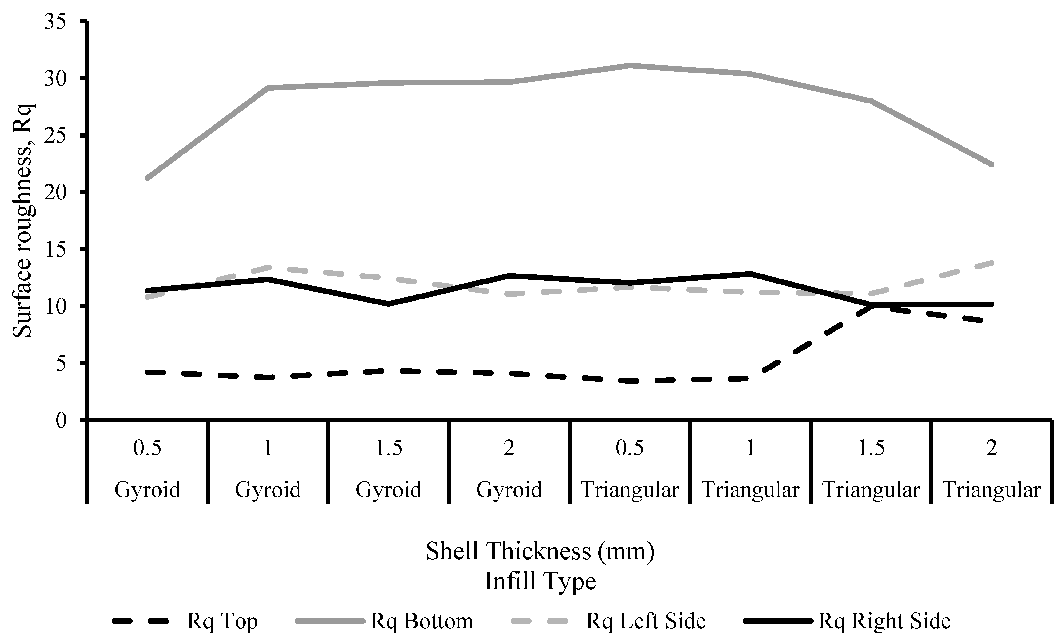
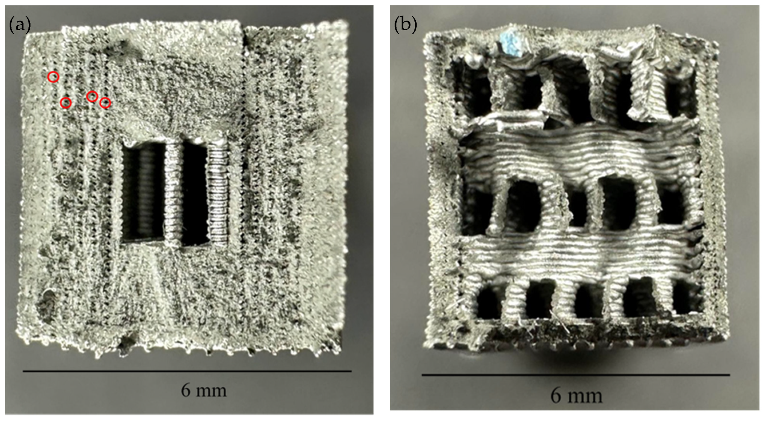
3.3. Surface Roughness

The measured surface roughness values for each specimen are shown in Figure 8. Although the arithmetic mean deviation (Ra) of the surface roughness is commonly used, the Rq value will be used for comparisons, as it is a better parameter to assess the average of surface roughness, as the graphs were sinusoidal in form. Thus, it was better to take an average that accounts for the root mean square (RMS), which Rq can. Rq may be used to determine whether the profile has projecting peaks that might have an effect on the function of the part [33]. The average Rq of the specimens was 5.27 μm on the top, whereas an average of 27.70 μm was recorded for the bottom. It was obvious that for all specimens, surface roughness at the bottom of the specimen was significantly higher when compared to the top surface. This was due to the presence of rafts at the bottom of the specimens, which were removed after printing. Traditional 3D printers printing polymeric components were able to achieve relatively smooth surface finishes [34] due to the absence of the sintering process. A smooth surface commonly had trends with good tensile strength, as crack propagation initially occurs at the surface of a specimen, where metal particles are not fully surrounded by other metal particles [35]. Miniature cracks can develop and cause larger cracks to propagate throughout the structure of the specimen, causing failure of the specimen at strengths much lower than predicted.
The specimens had an average side roughness (Rq) of 11.71 μm. Layer thickness had an important role in the surface roughness on the side of a specimen. Each layer was adjoined on top of the other, so if there were issues with the previous layer’s adhesion, it would also impact the next one. Also, smaller layer thicknesses can have smaller valleys and peaks between each other in the horizontal orientation of the specimen, and layer height was dependent upon nozzle diameter.

3.4. Tensile Test

Stress–strain graphs of the specimens are plotted in Figure 9, together with a wrought [33] and manufacturer’s claimed graph [33] for comparison purposes. The extracted mechanical properties of the specimens, like yield stress, ultimate tensile strength and strain % at break, are tabulated in Table 4. According to the manufacturer, the yield stress of the specimens was expected to achieve close to 800 MPa; however, results show a maximum recorded value of 252.9 MPa. The reason for this discrepancy was that the claimed values from the manufacturers were most likely conducted by a specimen with maximum solid-like structure, i.e., the maximum density of infill and shell thickness possible to create the strongest possible specimen. However, no fully solid specimens were created for this testing, as this was not required to assess shell thickness or infill type, and therefore, due to the presence of infill, the maximum potentiality of the mechanical properties might not have been able to be achieved. From Figure 9, it can be seen that there was a direct correlation between the increase in shell thickness and the increase in the specimen’s ultimate tensile strength. Specimens that exhibit different infill types but have the same shell thickness tend to output a similar ultimate tensile strength. All specimens showed little or no signs of necking; brittle failure was quite frequently observed during tensile testing, with maximum elongation around 12.54% at break point. This result was expected, as 17-4 PH is known as a martensitic, precipitation-hardening stainless steel with brittle-like fracture appearance. Moreover, the ultimate tensile strength was about 4.88% lower.
It was not possible to directly compare the present data to those of the literature, as the printing parameters used to fabricate specimens in the present case were substantially different to those of the literature [17,21,23,26]. Having said that, data presented in the literature on the same material (17-4 PH stainless steel) system but different printing parameters were as follows: Burgess et al. [17] reported 395–1050 MPa of UTS and 28–37 HRC of hardness; Sambrook et al. [21] reported 550–730 MPa of UTS and 280–442 HV of hardness; Thawon et al. [23] reported 809.89 MPa of UTS and 115.05–271.97 MPa of hardness; and Godec et al. [26] reported 9.95 MPa of UTS for the ‘green parts’ (before sintering) only.
The triangular infill pattern regularly outperformed the gyroid infill pattern in terms of ultimate tensile strength when the same shell thickness was compared (Figure 10). This could be due to the lack of support structure in the direction of load for the gyroid infill pattern. However, the gyroid infill pattern tended to have a longer elongation than the triangular infill. This may be due to the longer individual strands of the print present in the triangular infill pattern, whereas the gyroid infill had fewer length strands but a higher quantity of individual strands at the gauge area. The gyroid infill also had an alternating pattern of infill between every few printed layers, as seen in Figure 11. As the specimen was pulled apart by the tensile machine, the strands were assumed to be individually broken by having more strands present, and in alternative formation, a greater elongation distance was achieved by gyroid infill pattern.
A strong relationship between measured mass and UTS was present, as shown in Figure 12. An increase in specimen mass directly translated to an increase in UTS. This was mainly due to the variation of shell thickness throughout the specimens. Shell thickness was a key component in specimen strength, and as there was more shell thickness available due to the extra mass of the specimen, the UTS increased accordingly. A 79.97% difference in sample mass was seen between the specimens, whereas a 180.44% difference was seen in UTS between the specimens. In summary, samples’ internal geometries were influenced by the use of the specific infill type and shell thicknesses. Higher infill density and greater shell thickness obviously deposited more material and resulted in more mass compared to that of lower infill density and smaller shell thickness. This was corelated with the obtained mechanical properties (like YS and UTS), as reported in Figure 10 and Figure 12.

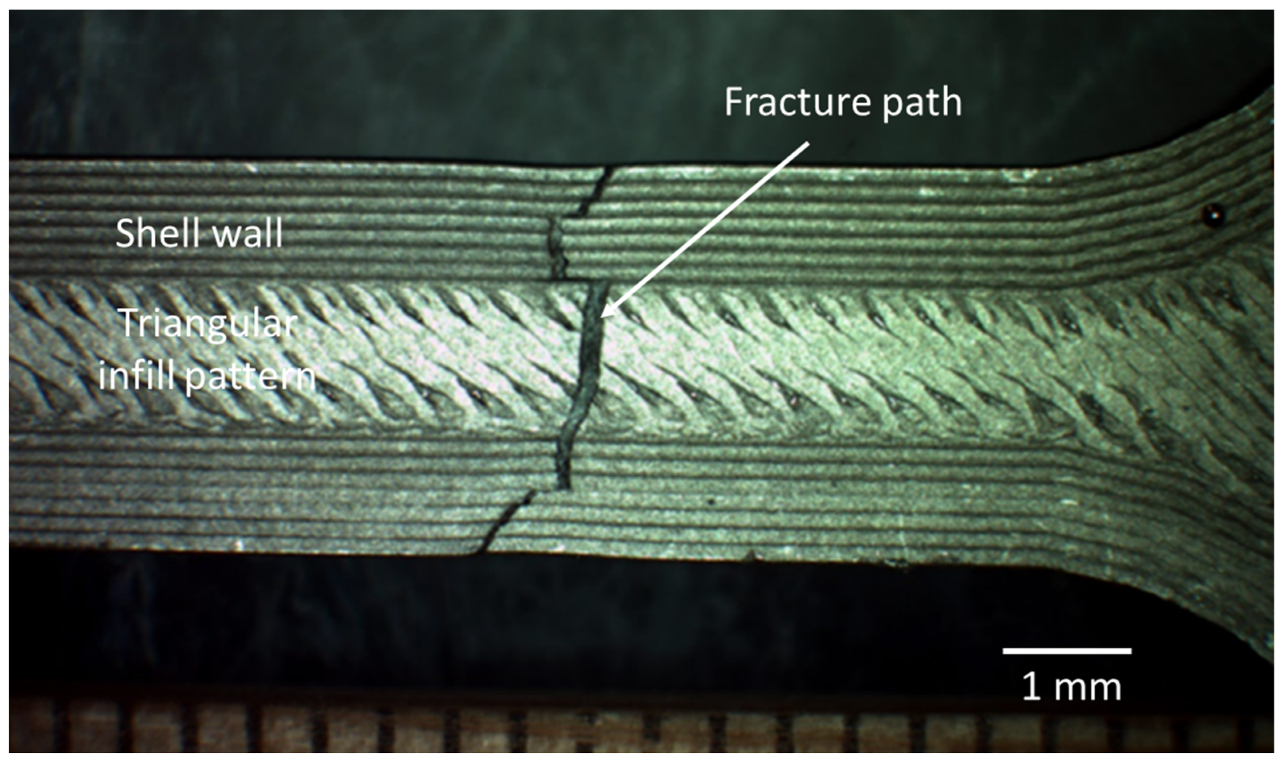
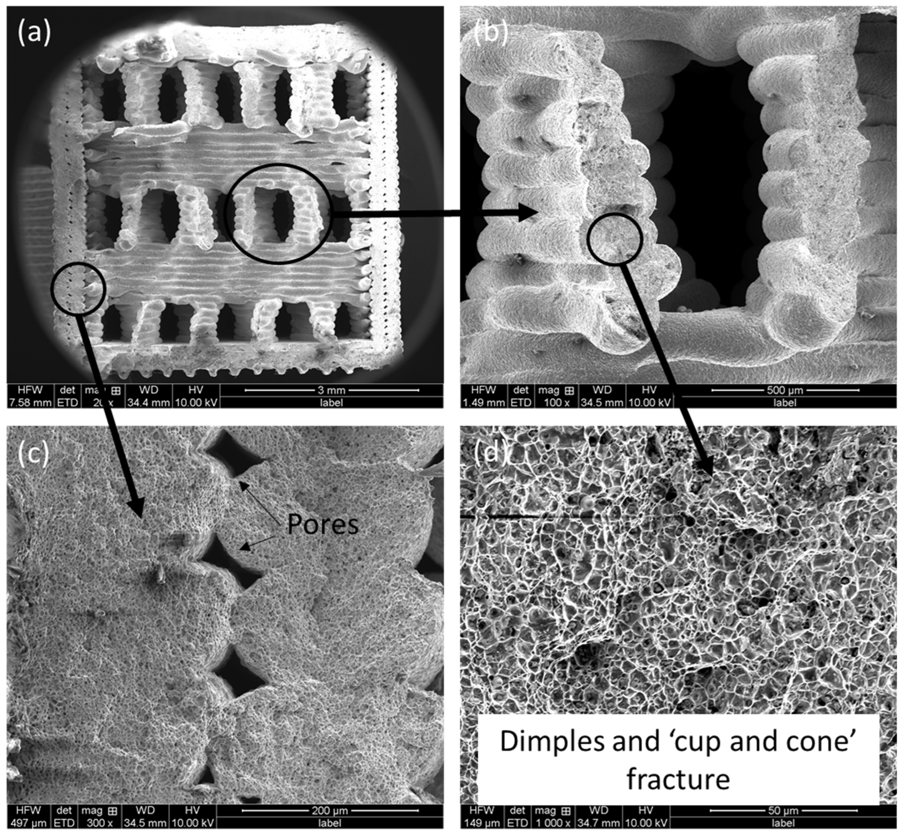
3.5. Fracture Surface Morphology

The top-view and cross-section of the failed tensile test specimens were investigated further by optical and electron microscope to understand their fracture morphology. A representative optical microscope image (top-view) of a failed specimens is shown in Figure 13. Striation-like features were noticed and the shell wall, triangular infill pattern and fracture path were evident. The change of direction of the fracture path indicated that the crack was deflected in the interface of the shell and core of the specimen.
Representative cross-section fractography of the gyroid and triangular infill pattern specimens are shown in Figure 14 and Figure 15, respectively. Irrespective of the specimens, it can be seen that there are two distinct zones, namely the shell wall and the inner core filled with either gyroid (Figure 14) or triangular (Figure 15) infill pattern. The shell wall represents complete fusion, withstanding voids formation among between the corners of the metal stands (Figure 14c and Figure 15b,c). These pores/voids were present throughout the shell thickness, and their even spread conveys that this was a repetitive structure that formed during specimen printing. These were the typical void forms that occur due to incomplete fusion during the sintering process, as reported in the literature [7,23]. The core of the gyroid infill pattern specimen showed good fusion among the metal stands (Figure 14b), and the fracture mode was ductile fracture with representative dimple formation, together with ‘cup and cone’ appearance (Figure 14d). Strands of metal were laid down by the print nozzle and held together by a binder, which washed away during chemical debinding and sintering. However, the binder escaped through these holes, and sintering occurred where strand-to-strand diffusion took place in the metal particles. This was well known in the extrusion-based AM as a manufacturer’s error that had not been addressed and led to porosity introduction in the samples [7,23].
A higher magnified image (Figure 15d) on the triangular infill pattern specimen also demonstrates similar ductile fracture featuring dimples and ‘cup and cone’, together with unmelted particles.
The feed stock during the printing process was metal powder with polymer binder. The polymer binder burnt out during the sintering process, which gave rise to various gasses such as carbon dioxide and hydrogen and shoots like carbon due to the lack of oxygen in the argon-rich environment [36]. These trapped gases not only gave rise to pores but also voids, particularly in the corners of the metal strands, due to “inadequate sintering time or temperature, and quite possibly insufficient chemical de-binding time” [37]. The shell wall of the specimens first heated up during the sintering process and fused the metal layers. As the process continued, the heat continued to flow towards the inner core of the specimen where it became fused and densified. The evidence in Figure 14 and Figure 15 suggests that the inner core of the specimens was not fused completely, which might be related to lack of sintering time, temperature or both. The whole sintering process and associated parameters were proprietary property of the manufacture, and thus, they were beyond the scope of adjustment, which required further refinement.

4. Conclusions

The present investigation reports on the effect of varying input parameters on the dimensional accuracy and tensile properties on specimens manufactured by ADAM. From the observed results and analysis, the following conclusions could be made:
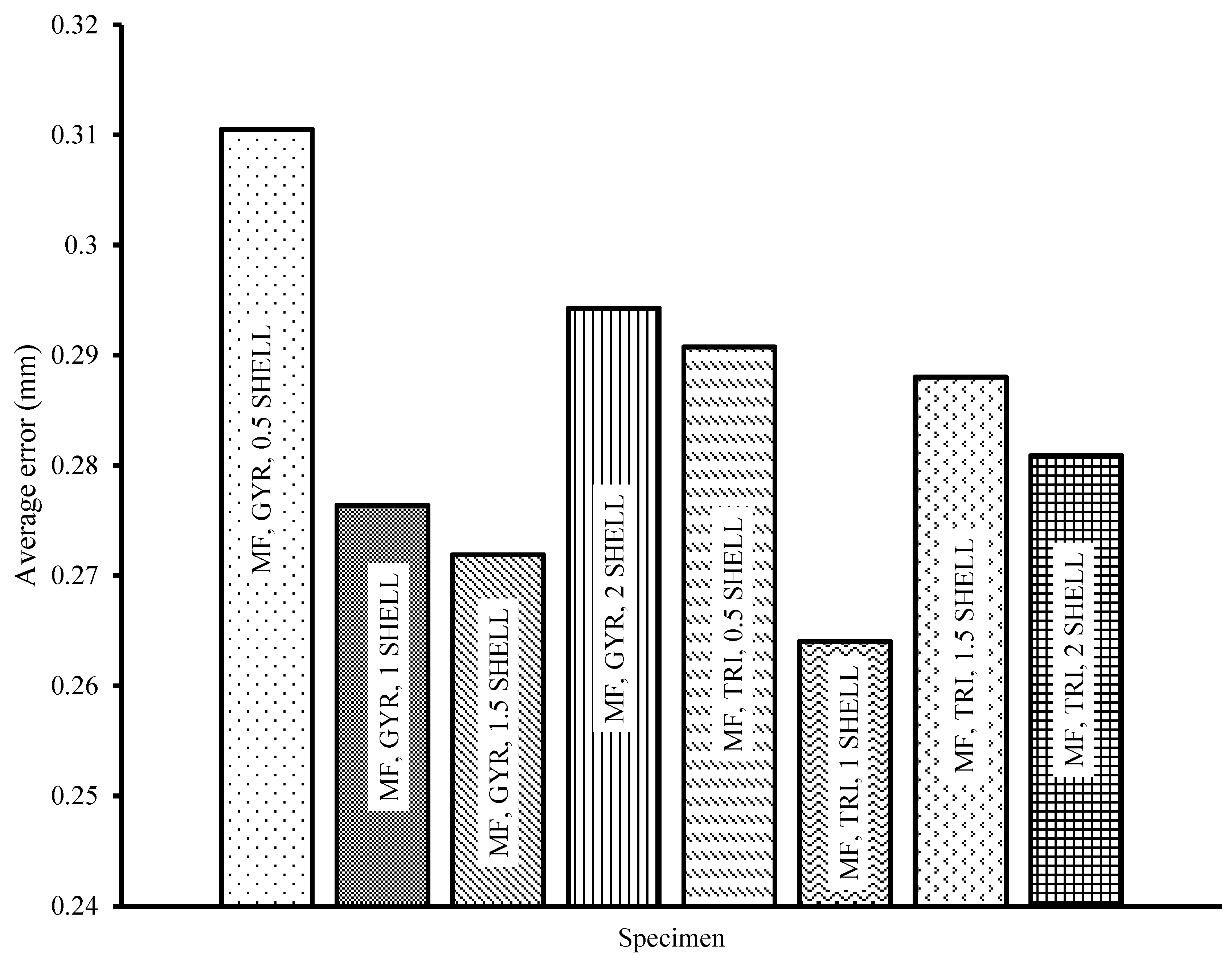
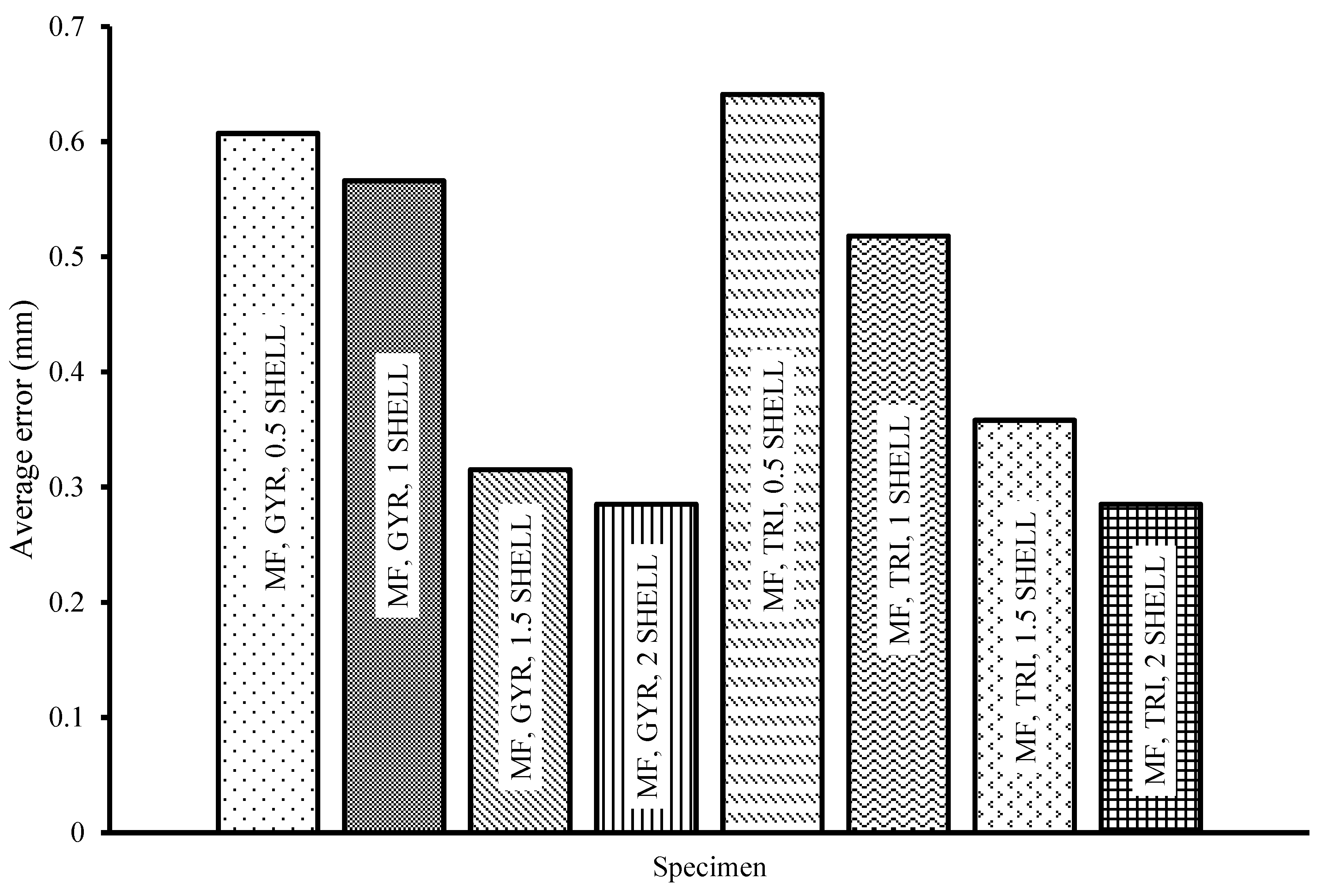
  • Results from the coordinate measuring machine showed there were inconsistencies in the print quality of the ADAM processes. Toolpath geometry, staircasing and sintering technology could be reasons for the discrepancies; however, when compared with traditional casting and forging of similar steel, international tolerance grades can be achieved. Overall length error was at a maximum when shell thickness was at a minimum value. Triangular infill specimens saw a decrease in cylindricity error and an increase in gauge length error when compared to gyroid fill. All of these errors were in an acceptable range by the international tolerance (IT) grades of ISO 286.
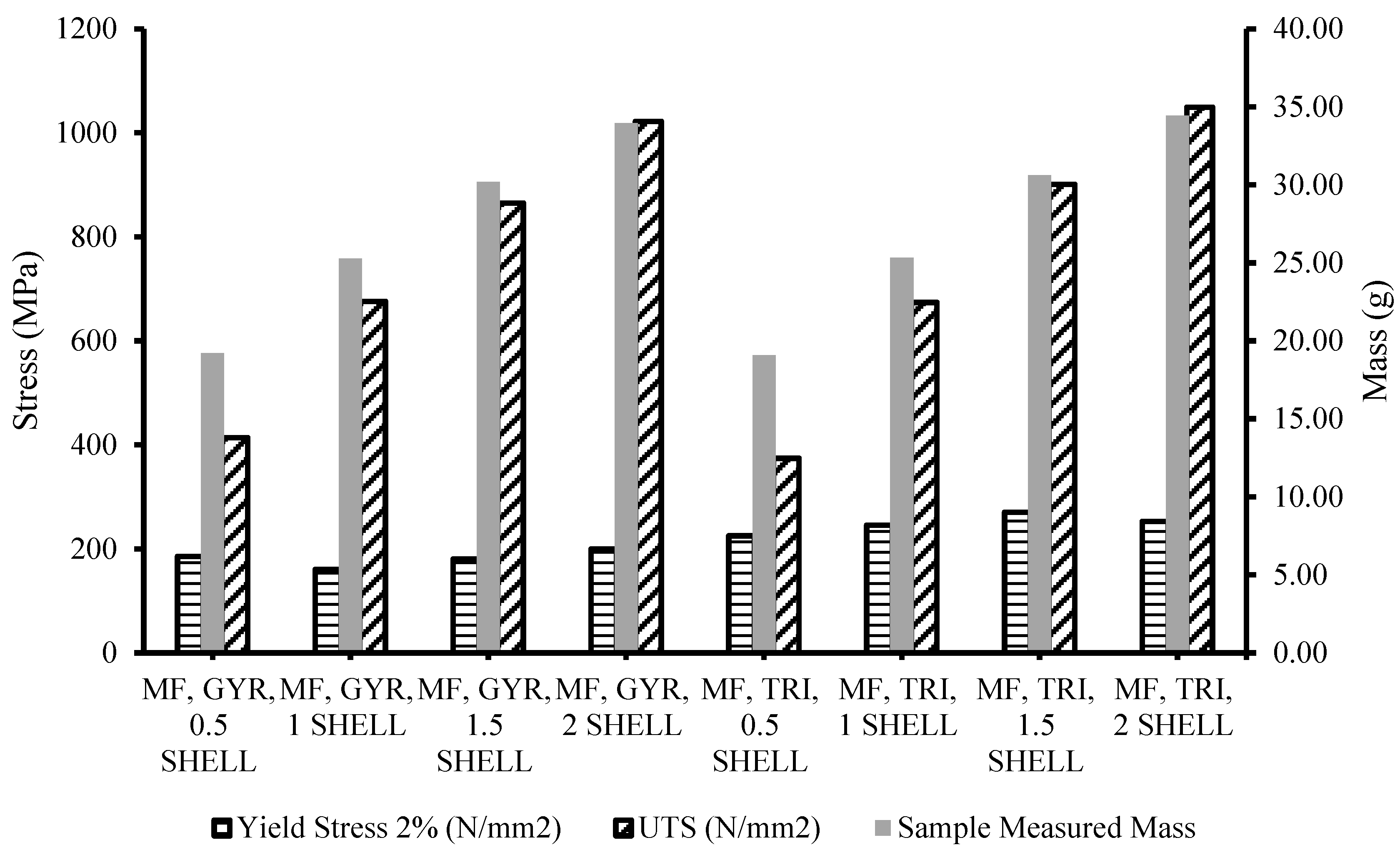
  • A minimal difference in mass (1.5%) was observed when the infill type was changed. A 21.6% increase in specimens’ mass was observed when shell thickness was increased in each iteration. Parts printed by ADAM can have up to ¼ mass savings when compared to traditional manufacturing, at the expense of the parts’ strength.
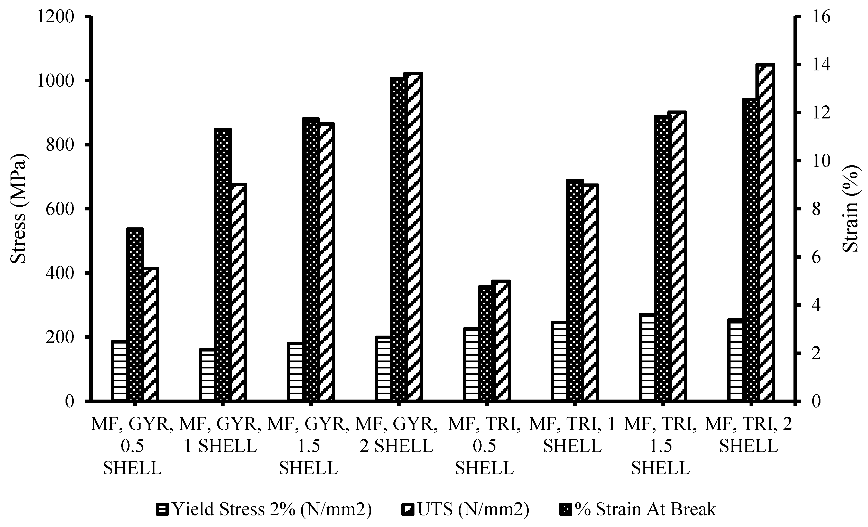
  • The specimens showed comparable ultimate tensile strength (1049.1 MPa), matching the claims of the manufacturer (1050 MPa), together with elongation at break, though they were about 4.88% lower in ultimate tensile strength. The specimens showed an increase in ultimate tensile strength when the shell thicknesses of specimens were increased. The two different infill types saw minimal changes, although it should be noted that triangular specimens exhibited greater ultimate tensile strength, whereas the gyroid had slightly longer elongation at break.
  • Microscopic analysis of specimens showed deformities that include striations from tool path error. The cross-section of the tensile tested, broken specimen revealed significant pores in the microstructure and could contribute to a reduction in the mechanical properties of the specimens. Thus, further optimization of the sintering time and temperature was foreseen.
ADAM is a growing and developing technique in its early stages. Outcomes from its processes now may be extremely different from their outputs in the near future with greater access to technology and research. Many input parameters are able to be tested, but this investigation only considered two. Countless more can be varied to ultimately refine and optimize print parameters for maximum quality of print features and properties for ADAM.

Author Contributions

A.K.B.: conceptualization, experiment, writing—review and editing; J.M.S.: experiment, formal analysis, validation, data curation, writing—review and editing; A.P.: resource, conceptualization, supervision, writing—review and editing. All authors have read and agreed to the published version of the manuscript.

Funding

This research received no external funding.

Data Availability Statement

The raw/processed data used to produce the results will be made available by the corresponding author upon reasonable request.

Conflicts of Interest

The authors declare that they have no known competing financial interests or personal relationships whatsoever that could have influenced the work reported in this paper.

References

  1. Henry, T.C.; Morales, M.A.; Cole, D.P.; Shumeyko, C.M.; Riddick, J.C. Mechanical behavior of 17-4 PH stainless steel processed by atomic diffusion additive manufacturing. Int. J. Adv. Manuf. Technol. 2021, 114, 2103–2114. [Google Scholar] [CrossRef]
  2. Basak, A.K.; Celis, J.-P.; Vardavoulias, M.; Matteazzi, P. Effect of nanostructuring and Al alloying on friction and wear behaviour of thermal sprayed WC–Co coatings. Surf. Coat. Technol. 2012, 206, 3508–3516. [Google Scholar] [CrossRef]
  3. Basak, A.; Matteazzi, P.; Vardavoulias, M.; Celis, J.-P. Corrosion-wear behaviour of thermal sprayed nanostructured FeCu/WC–Co coatings. Wear 2006, 261, 1042–1050. [Google Scholar] [CrossRef]
  4. Bajaj, P.; Hariharan, A.; Kini, A.; Kürnsteiner, P.; Raabe, D.; Jägle, E.A. Steels in additive manufacturing: A review of their microstructure and properties. Mater. Sci. Eng. A 2020, 772, 138633. [Google Scholar] [CrossRef]
  5. Attaran, M. The rise of 3-D printing: The advantages of additive manufacturing over traditional manufacturing. Bus. Horiz. 2017, 60, 677–688. [Google Scholar] [CrossRef]
  6. Galati, M.; Minetola, P. Analysis of density, roughness, and accuracy of the atomic diffusion additive manufacturing (ADAM) process for metal parts. Materials 2019, 12, 4122. [Google Scholar] [CrossRef]
  7. Basak, A.; Lee, A.; Pramanik, A.; Neubauer, K.; Prakash, C.; Shankar, S. Material extrusion additive manufacturing of 17-4 PH stainless steel: Effect of process parameters on mechanical properties. Rapid Prototyp. J. 2023, 29, 1097–1106. [Google Scholar] [CrossRef]
  8. Bjørheim, F.; Lopez, I.L.T. Tension testing of additively manufactured specimens of 17-4 PH processed by Bound Metal Deposition. In IOP Conference Series: Materials Science and Engineering; IOP Publishing: Bristol, UK, 2021; p. 12037. [Google Scholar]
  9. Gonzalez-Gutierrez, J.; Cano, S.; Schuschnigg, S.; Kukla, C.; Sapkota, J.; Holzer, C. Additive manufacturing of metallic and ceramic components by the material extrusion of highly-filled polymers: A review and future perspectives. Materials 2018, 11, 840. [Google Scholar] [CrossRef]
  10. Gabilondo, M.; Cearsolo, X.; Arrue, M.; Castro, F. Influence of build orientation, chamber temperature and infill pattern on mechanical properties of 316l parts manufactured by bound metal deposition. Materials 2022, 15, 1183. [Google Scholar] [CrossRef]
  11. Degnah, A.; Tabbakh, T.; Kurdi, A.; Basak, A.K. Role of precipitation and solute segregation on micro-scale deformation of additively manufactured Inconel 718. Mater. Sci. Eng. A 2023, 887, 145762. [Google Scholar] [CrossRef]
  12. Becker, T.H.; Kumar, P.; Ramamurty, U. Fracture and fatigue in additively manufactured metals. Acta Mater. 2021, 219, 117240. [Google Scholar] [CrossRef]
  13. Tabbakh, T.; Alshihri, S.; Basak, A.; Kurdi, A. Strength of a 3D printed Al 7068 alloy under micro-pillar compression. Met. Mater. Int. 2022, 28, 2706–2718. [Google Scholar] [CrossRef]
  14. Ngo, T.D.; Kashani, A.; Imbalzano, G.; Nguyen, K.T.; Hui, D. Additive manufacturing (3D printing): A review of materials, methods, applications and challenges. Compos. Part B Eng. 2018, 143, 172–196. [Google Scholar] [CrossRef]
  15. Kurdi, A.; Basak, A. Micro-mechanical behaviour of selective laser melted Ti6Al4V under compression. Mater. Sci. Eng. A 2021, 826, 141975. [Google Scholar] [CrossRef]
  16. Chacón, J.M.; Caminero, M.A.; García-Plaza, E.; Núnez, P.J. Additive manufacturing of PLA structures using fused deposition modelling: Effect of process parameters on mechanical properties and their optimal selection. Mater. Des. 2017, 124, 143–157. [Google Scholar] [CrossRef]
  17. Burgess, A.; Dodd, R.; Radwani, M.; Opoz, T.; Tammas-Williams, S. The properties of stainless steel 17-4PH produced by a low-cost additive manufacturing technique, the Markforged MetalX™. J. Phys. Conf. Ser. 2022, 2198, 12057. [Google Scholar] [CrossRef]
  18. Vispute, M.; Kumar, N.; Taufik, M.; Jain, P.K. Improving surface finish of extrusion based additive manufactured parts using novel triangle based toolpath approach. Int. J. Interact. Des. Manuf. 2024, 18, 433–452. [Google Scholar] [CrossRef]
  19. Ajay, V.; Nakrani, J.; Mishra, N.K.; Shrivastava, A. Anisotropic fatigue crack propagation in wire arc additively manufactured 316L stainless steel. Int. J. Fatigue 2023, 177, 107976. [Google Scholar] [CrossRef]
  20. Sambrook, C. The Effect of Heat Treatment and Print Direction on Additively Manufactured 17-4 PH Stainless Steel. Master’s Thesis, The University of Greensland, St. Lucia, Australia, 2021. [Google Scholar]
  21. Rosnitschek, T.; Seefeldt, A.; Alber-Laukant, B.; Neumeyer, T.; Altstädt, V.; Tremmel, S. Correlations of geometry and infill degree of extrusion additively manufactured 316l stainless steel components. Materials 2021, 14, 5173. [Google Scholar] [CrossRef]
  22. Thawon, I.; Fongsamootr, T.; Mona, Y.; Suttakul, P. Investigation of the mechanical properties of additively manufactured metal parts with different relative densities. Appl. Sci. 2022, 12, 9915. [Google Scholar] [CrossRef]
  23. Basak, A.K.; Pramanik, A.; Chen, Y.X.; Prakash, C.; Radhika, N.; Shankar, S. Bound metal deposition of stainless steel 316L: Effect of process variables on microstructural and mechanical behaviors. Materialia 2024, 36, 102196. [Google Scholar] [CrossRef]
  24. Godec, D.; Cano, S.; Holzer, C.; Gonzalez-Gutierrez, J. Optimization of the 3D printing parameters for tensile properties of specimens produced by fused filament fabrication of 17-4PH stainless steel. Materials 2020, 13, 774. [Google Scholar] [CrossRef] [PubMed]
  25. Shakeri, Z.; Benfriha, K.; Shirinbayan, M.; Ahmadifar, M.; Tcharkhtchi, A. Mathematical modeling and optimization of fused filament fabrication (FFF) process parameters for shape deviation control of polyamide 6 using Taguchi method. Polymers 2021, 13, 3697. [Google Scholar] [CrossRef] [PubMed]
  26. Raju, N.; Warren, P.; Subramanian, R.; Ghosh, R.; Raghavan, S.; Fernandez, E.; Kapat, J. Material Properties of 17-4PH Stainless Steel Fabricated by Atomic Diffusion Additive Manufacturing (ADAM). In Proceedings of the 32nd Annual International Solid Freeform Fabrication Symposium—An Additive Manufacturing Conference, Austin, TX, USA, 2–4 August 2021. [Google Scholar]
  27. Rodriguez, J.; Zuriarrain, A.; Madariaga, A.; Arrazola, P.J.; Dominguez, E.; Fraile, I.; Soler, D. Mechanical Properties and Fatigue Performance of 17-4 PH Stainless Steel Manufactured by Atomic Diffusion Additive Manufacturing Technology. J. Manuf. Mater. Process. 2023, 7, 172. [Google Scholar] [CrossRef]
  28. Bouaziz, M.A.; Djouda, J.M.; Kauffmann, J.; Hild, F. Microscale mechanical characterization of 17-4PH stainless steel fabricated by Atomic Diffusion Additive Manufacturing (ADAM). Procedia Struct. Integr. 2020, 28, 1039–1046. [Google Scholar] [CrossRef]
  29. Bouaziz, M.; Djouda, J.M.; Chemkhi, M.; Rambaudon, M.; Kauffmann, J.; Hild, F. Heat treatment effect on 17-4PH stainless steel manufactured by Atomic Diffusion Additive Manufacturing (ADAM). Procedia CIRP 2021, 104, 935–938. [Google Scholar] [CrossRef]
  30. Hsiao, C.; Chiou, C.; Yang, J. Aging reactions in a 17-4 PH stainless steel. Mater. Chem. Phys. 2002, 74, 134–142. [Google Scholar] [CrossRef]
  31. ASTM E8/E8M-16a; Standard Test Methods for Tension Testing of Metallic Materials. ASTM International: West Conshohocken, PA, USA, 2016.
  32. ISO 286-1: 2010; Geometrical Product Specifications (GPS)—ISO Code System for Tolerances on Linear Sizes. International Organization for Standardization: Geneva, Switzerland, 2010.
  33. Markforged. Available online: https://markforged.com/materials/metals/17-4-ph-stainless-steel (accessed on 21 May 2025).
  34. Nigam, A.; Tai, B.L. Effects of in-process surface finishing on part strength in polymer material extrusion additive manufacturing. Addit. Manuf. 2024, 80, 103960. [Google Scholar] [CrossRef]
  35. Purnowidodo, A.; Arief, S.S.; Iman, F.H. Effect surface roughness on fatigue crack propagation behaviour of fibre Metal Laminates (FMLs). Int. J. Automot. Mech. Eng. 2019, 16, 6588–6604. [Google Scholar] [CrossRef]
  36. Burge, S.J.; Tipper, C. The burning of polymers. Combust. Flame 1969, 13, 495–505. [Google Scholar] [CrossRef]
  37. Thompson, Y.; Zissel, K.; Förner, A.; Gonzalez-Gutierrez, J.; Kukla, C.; Neumeier, S.; Felfer, P. Metal fused filament fabrication of the nickel-base superalloy IN 718. J. Mater. Sci. 2022, 57, 9541–9555. [Google Scholar] [CrossRef] [PubMed]
Figure 1. Triangular (a) and gyroid (b) infill pattern.
Designs 09 00066 g001
Figure 2. Visualization of shell thickness: 0.5 mm (a) and 3.5 mm (b).
Designs 09 00066 g002
Figure 3. Cylindricity error in the specimens.
Designs 09 00066 g003
Figure 4. Staircase effect on 3D printed models: (a) thicker lines and (b) thinner lines.
Designs 09 00066 g004
Figure 5. Perpendicularity error in the specimens.
Designs 09 00066 g005
Figure 6. Vertical height error in the specimens.
Designs 09 00066 g006
Figure 7. Length error in the specimens.
Designs 09 00066 g007
Figure 8. Effect of printing parameters on surface roughness (Rq).
Designs 09 00066 g008
Figure 9. Stress–strain curves of the ADAM specimens with wrought and manufacturer’s claimed curves * [33].
Designs 09 00066 g009
Figure 10. Comparison of the yield stress, ultimate tensile strength and strain % at break of the ADAM specimens.
Designs 09 00066 g010
Figure 11. Morphology of (a) triangular and (b) gyroid infill pattern on the specimen after tensile testing, showing different fracture mode. The red circles indicate the presence of pores.
Designs 09 00066 g011
Figure 12. Yield stress, UTS and measured mass of the specimens.
Designs 09 00066 g012
Figure 13. Striation-like features on the sample surface, together with fracture line and tool path (specimen: MF, TRI, 2 SHELL).
Designs 09 00066 g013
Figure 14. Fractography after tensile testing on a representative gyroid infill pattern specimen (MF, GYR, 0.5 SHELL): (a) overall fractured surface showing individual metal strands, (b) high-magnification view of metal strands, (c) pores among metal strands on shell wall and (d) dimples and ‘cup and cone’ representing ductile fracture.
Designs 09 00066 g014
Figure 15. Fractography after tensile testing on representative triangular infill pattern specimen (MF, TRI, 2 SHELL): (a) overall fractured surface showing individual layers, (b) pores among shell wall layers, (c) pores among individual layers on the core of the specimen and (d) dimples and ‘cup and cone’ representing ductile fracture.
Designs 09 00066 g015
Table 1. Specimen input parameter description.
Specimen NameShell Thickness (mm)Infill Type
MF, GYR, 0.5 SHELL0.5Gyroid
MF, GYR, 1 SHELL1Gyroid
MF, GYR, 1.5 SHELL1.5Gyroid
MF, GYR, 2 SHELL2Gyroid
MF, TRI, 0.5 SHELL0.5Triangular
MF, TRI, 1 SHELL1Triangular
MF, TRI, 1.5 SHELL1.5Triangular
MF, TRI, 2 SHELL2Triangular
Table 2. ISO 286 IT grades [32].
Nominal Size (mm)International Tolerance Grade (mm)
>IT11IT12IT13IT14IT15IT16
801200.220.350.540.871.42.2
Table 3. Masses of the printed specimens after sintering.
SpecimenMass (g)
MF, GYR, 0.5 SHELL19.21
MF, GYR, 1 SHELL25.28
MF, GYR, 1.5 SHELL30.19
MF, GYR, 2 SHELL33.94
MF, TRI, 0.5 SHELL19.07
MF, TRI, 1 SHELL25.32
MF, TRI, 1.5 SHELL30.62
MF, TRI, 2 SHELL34.42
Table 4. Mechanical properties of the ADAM specimens together with wrought and manufacture’s claimed values * [33].
Mechanical PropertiesADAM Specimen
(MF, TRI, 2 SHELL)
Manufacture Datasheet *Wrought Specimen *
Yield strength (MPa)252.98001000
Ultimate tensile strength (UTS, MPa)1049.110501103
Strain at break (%)12.5455
Young’s modulus (GPa)15.6140200
Hardness (HRB)290277322
Disclaimer/Publisher’s Note: The statements, opinions and data contained in all publications are solely those of the individual author(s) and contributor(s) and not of MDPI and/or the editor(s). MDPI and/or the editor(s) disclaim responsibility for any injury to people or property resulting from any ideas, methods, instructions or products referred to in the content.

