
Intelligent Inversion Analysis of Surrounding Rock Parameters and Deformation Characteristics of a Water Diversion Surge Shaft


Abstract
1. Introduction
2. PSO-SVM Inversion Method of Rock Mechanical Parameters
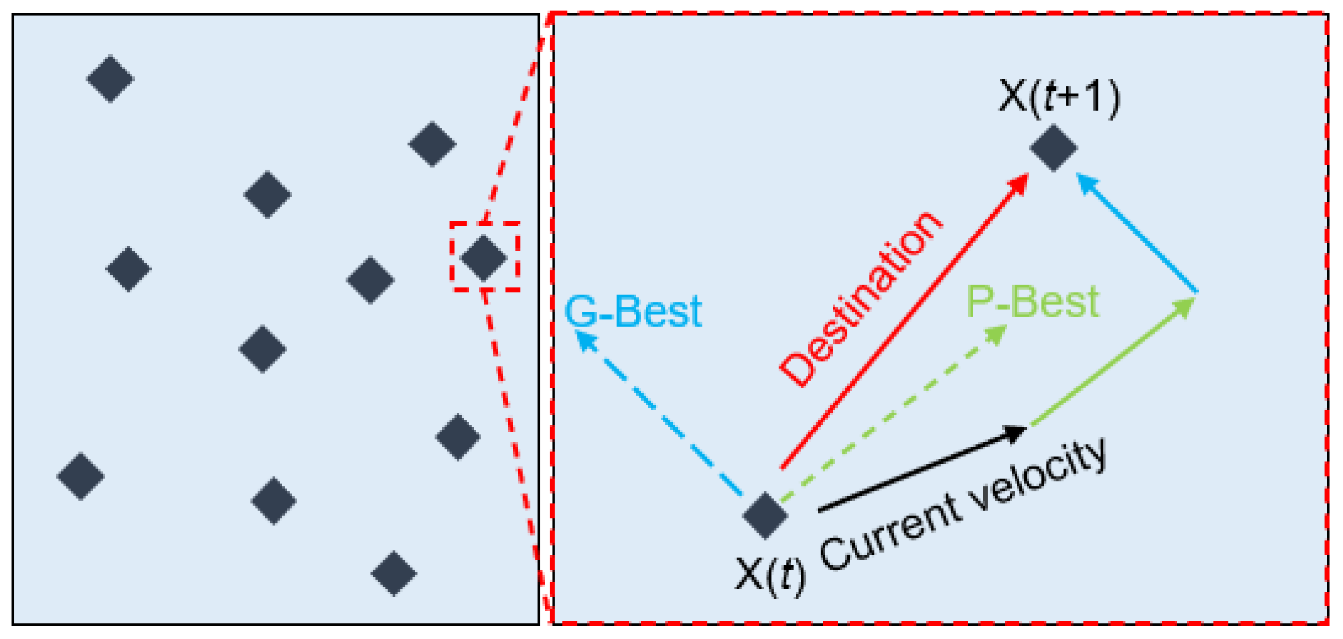
2.1. PSO Method
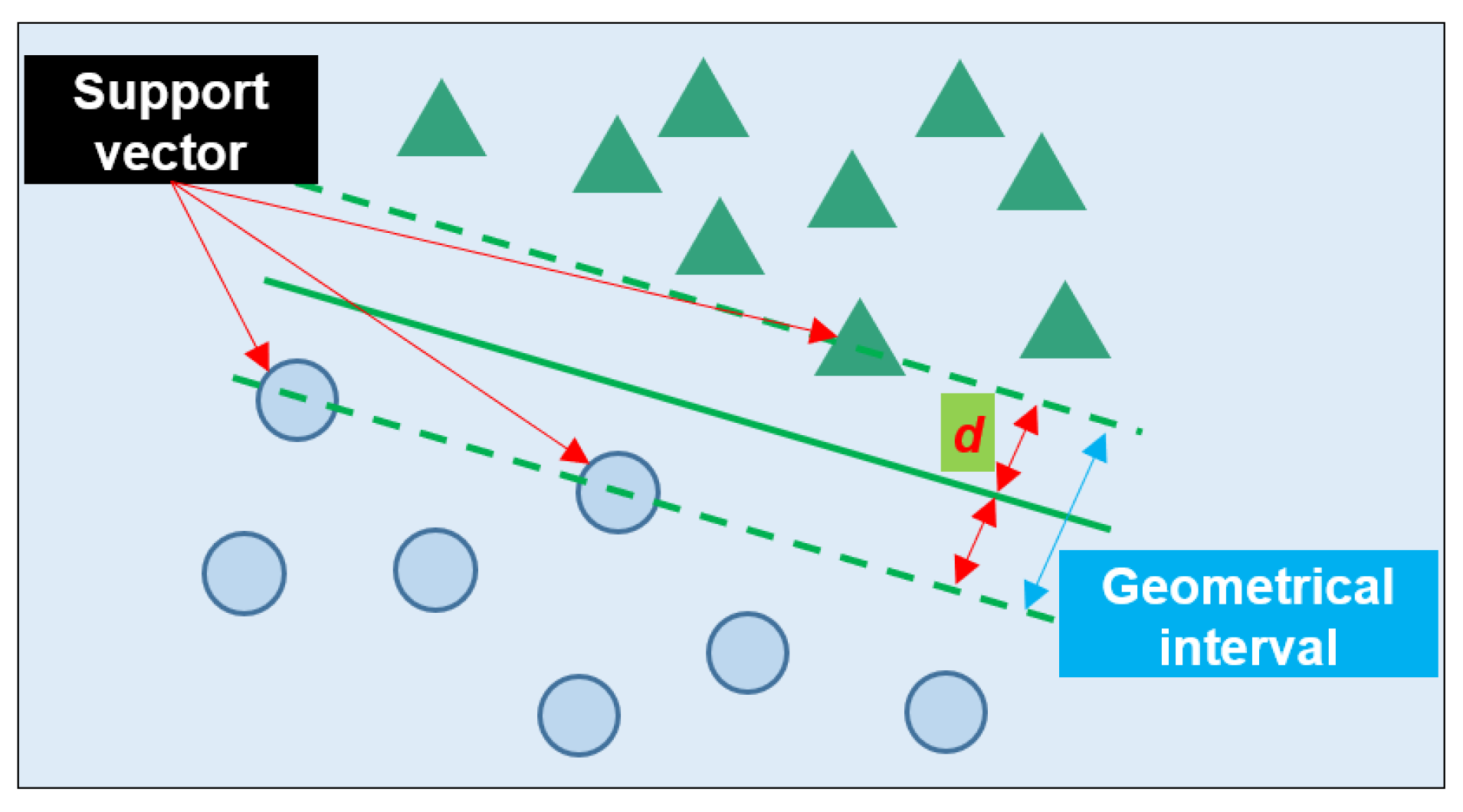
2.2. SVM Method
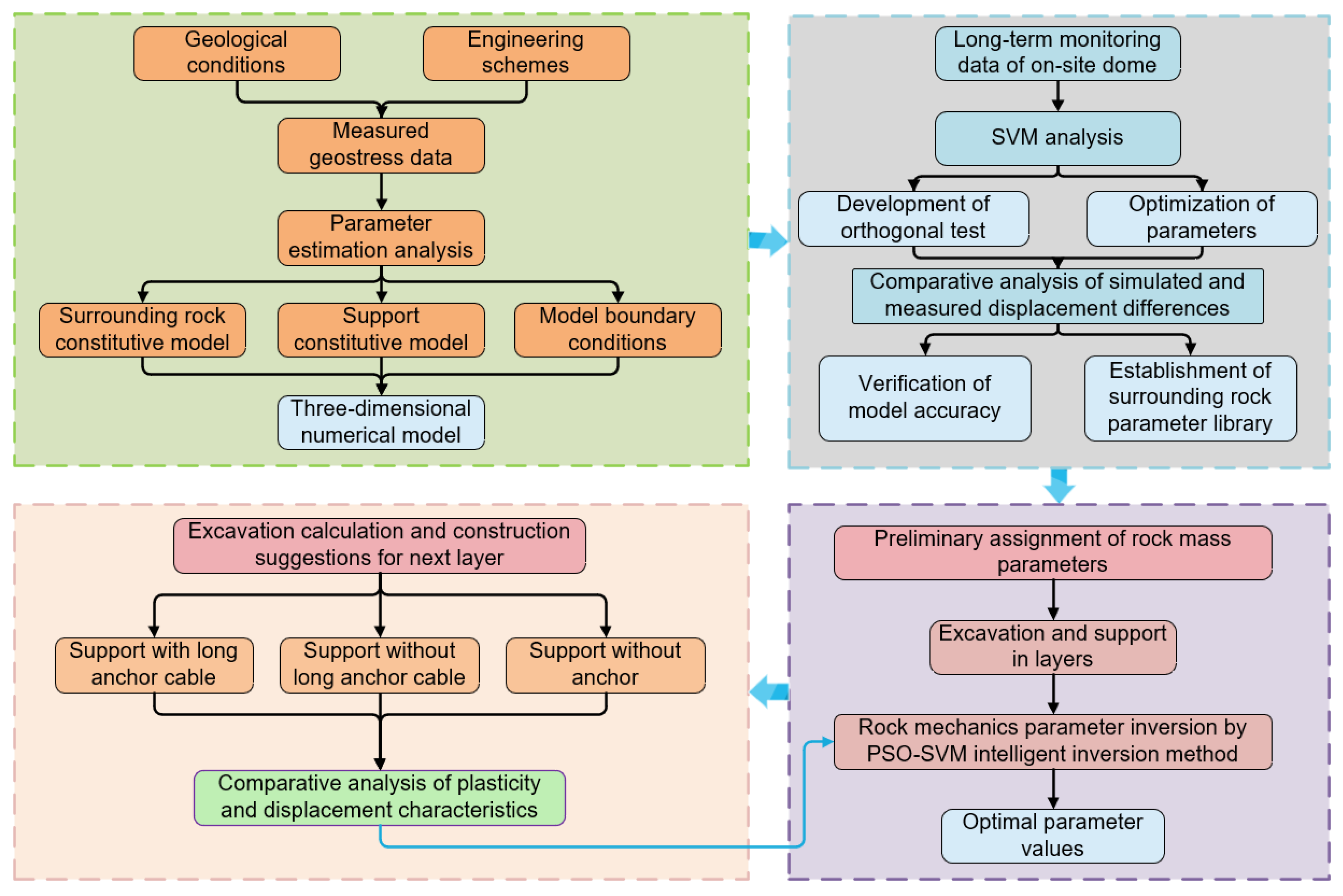
2.3. Inversion Steps of Rock Mechanical Parameters
3. Inversion of Surrounding Rock Parameters of Water Diversion Surge Shaft
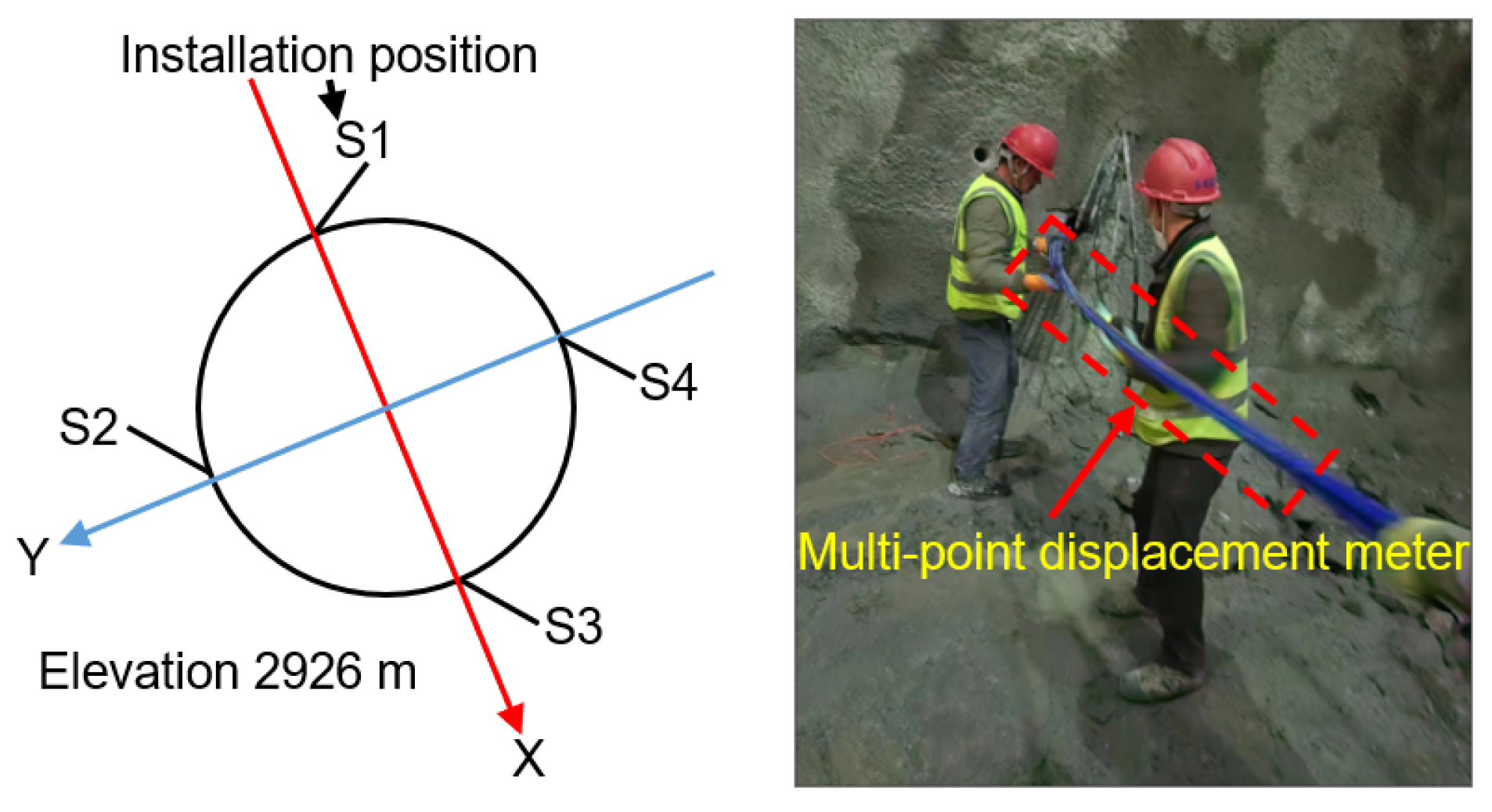
3.1. Engineering Situations
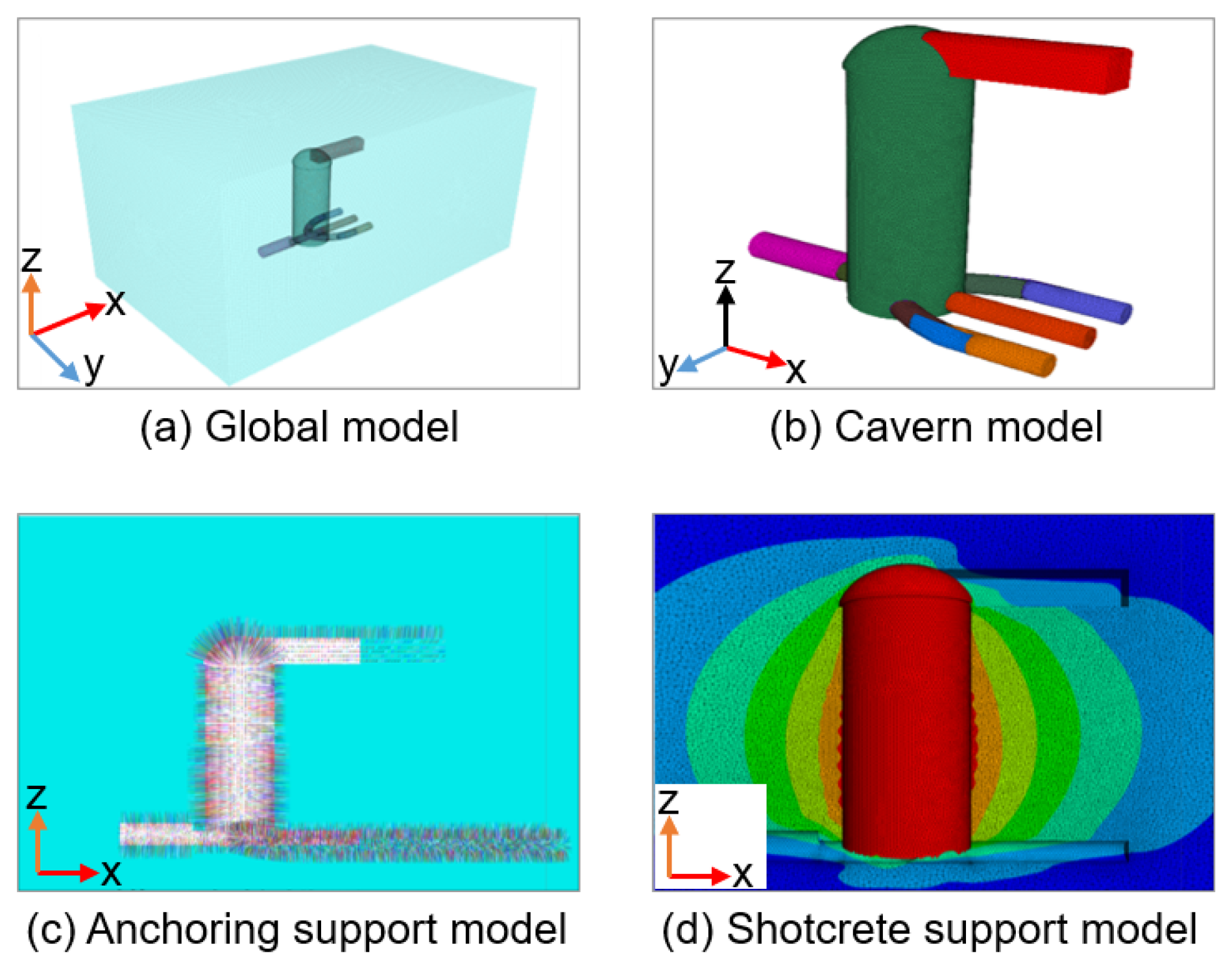
3.2. Construction of the Numerical Model
3.3. Parameter Inversion Results
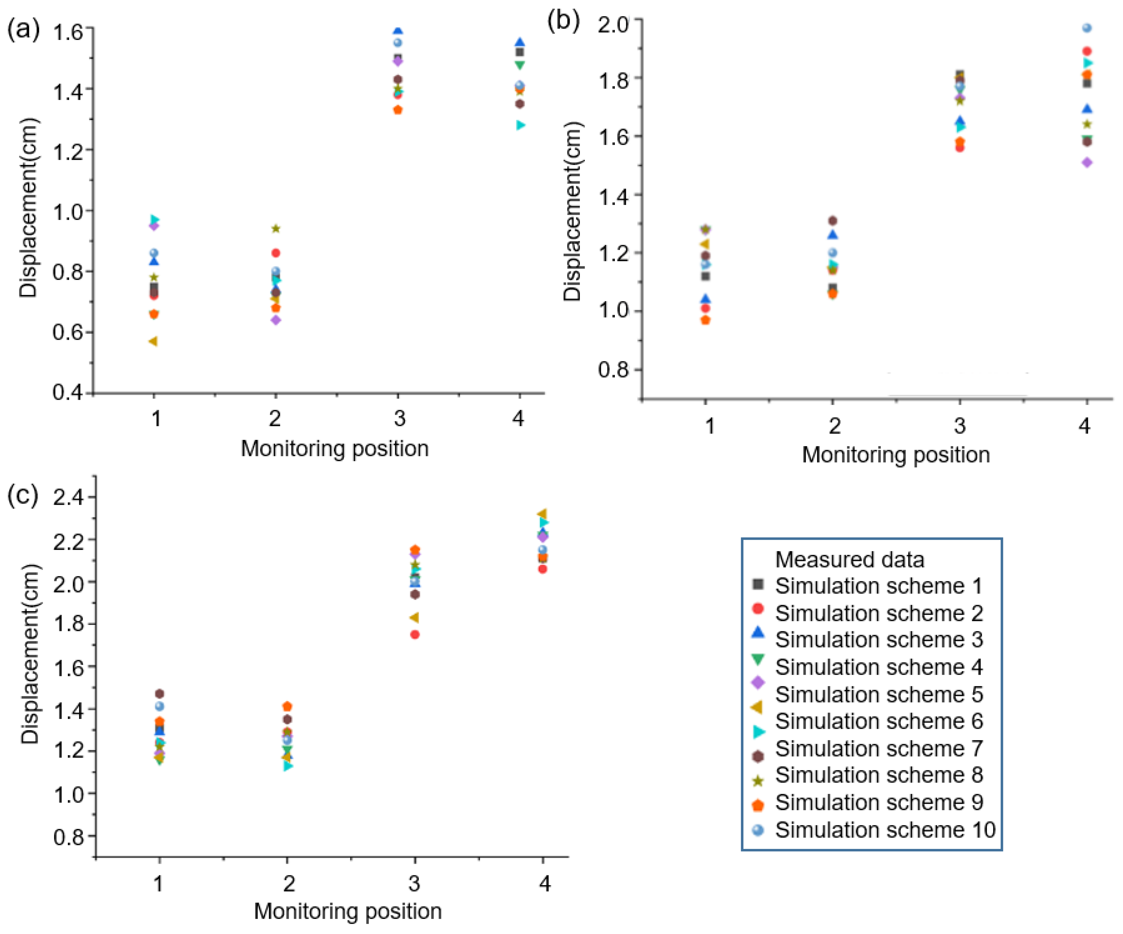
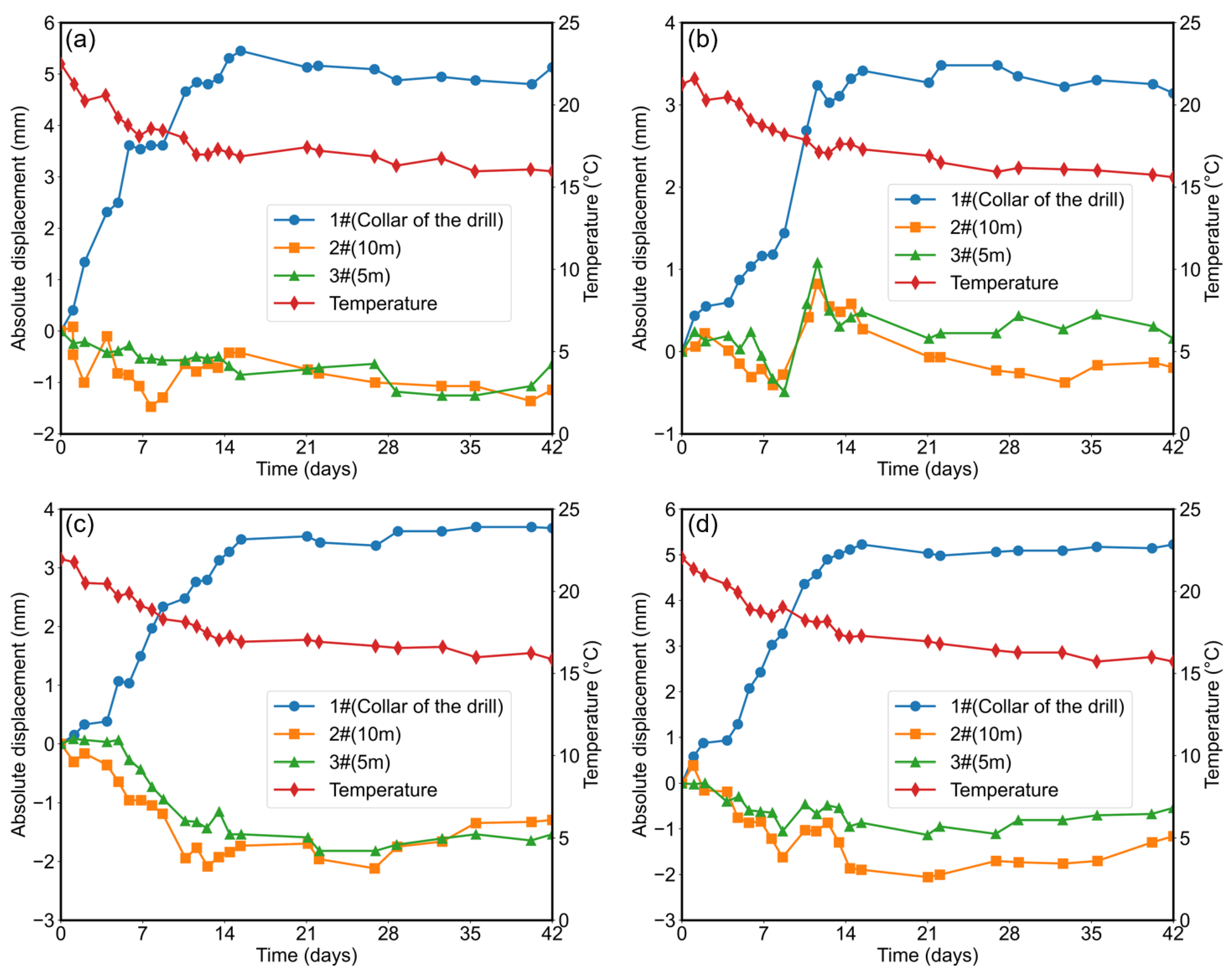
3.4. Comparison of Field Monitoring Data and Numerical Simulation Results
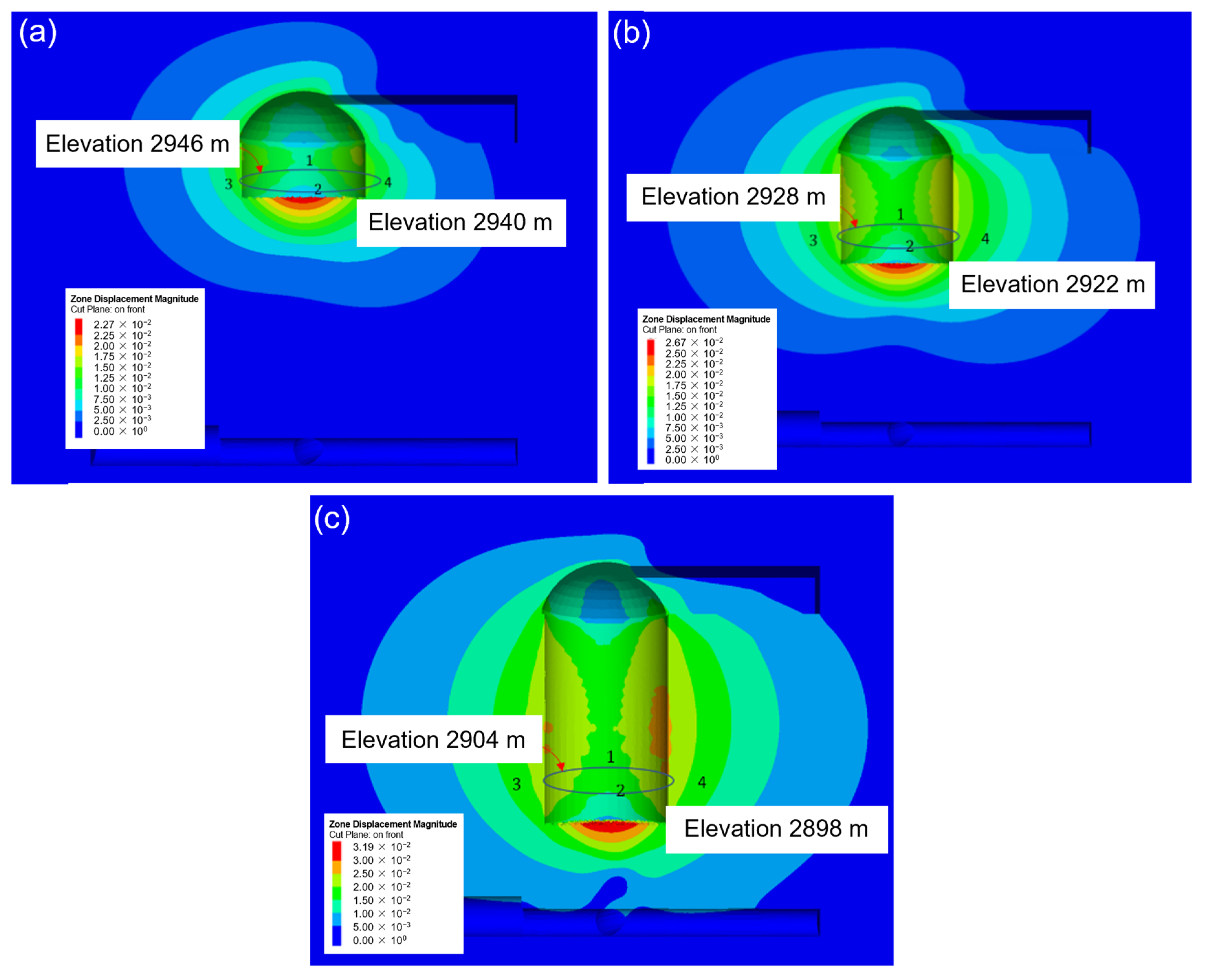
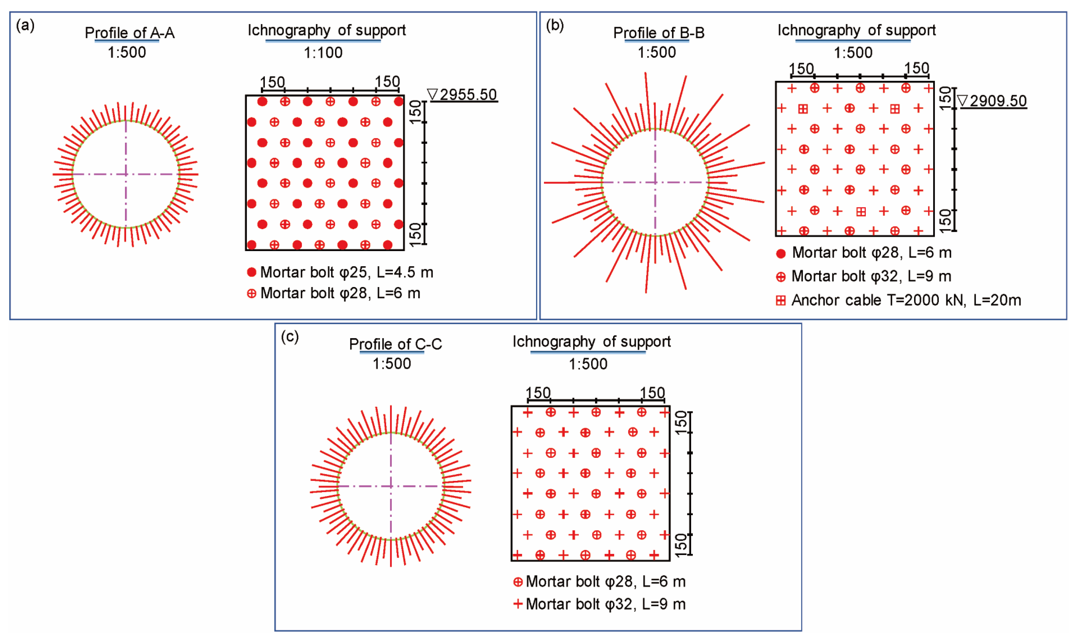
4. Analysis of Deformation Characteristics of Water Diversion Surge Shaft Under Different Supports During Layered Excavation
5. Response Characteristics of Surrounding Rock of Water Diversion Surge Shaft at the Excavation Completion Stage Under Different Support Schemes
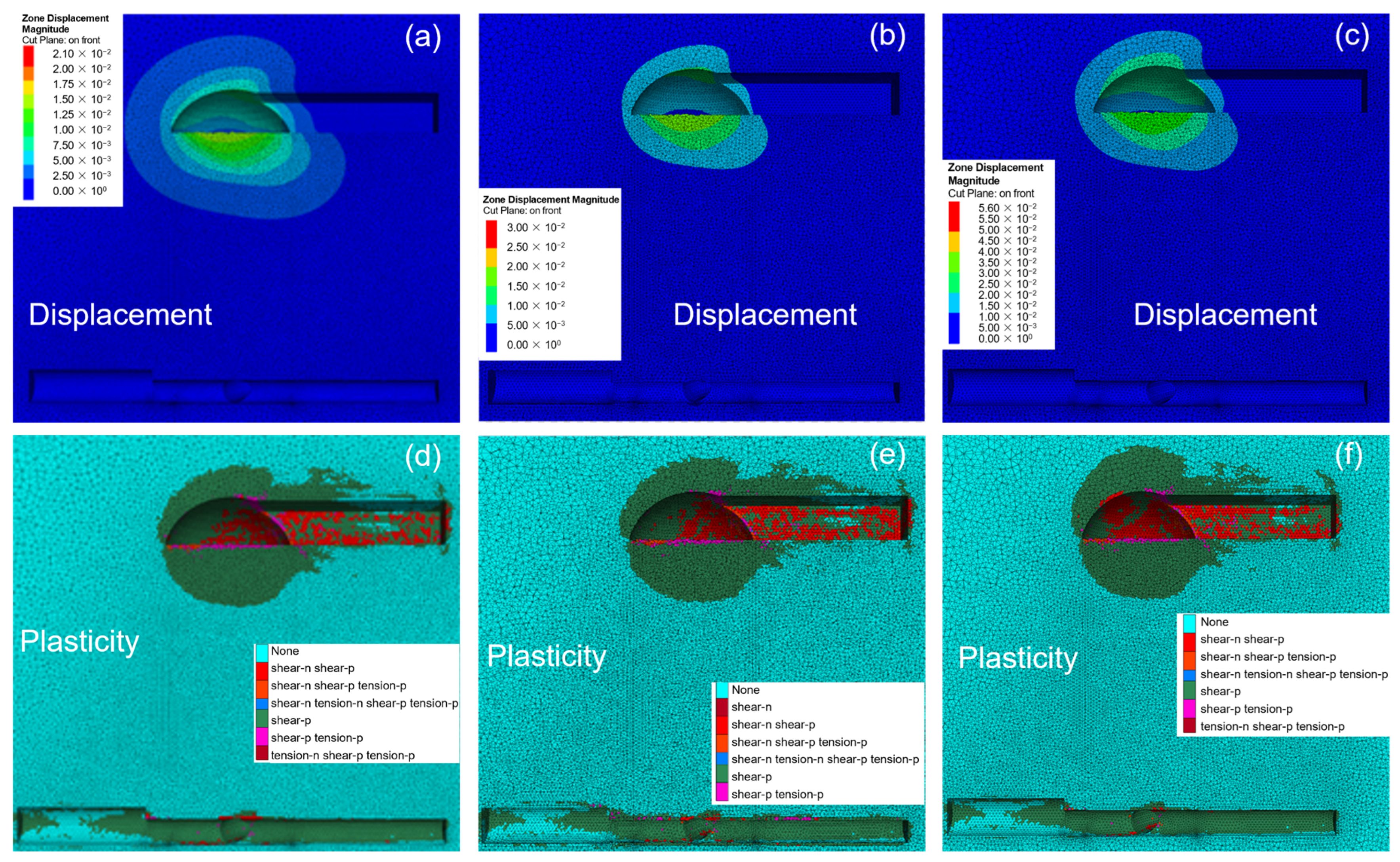
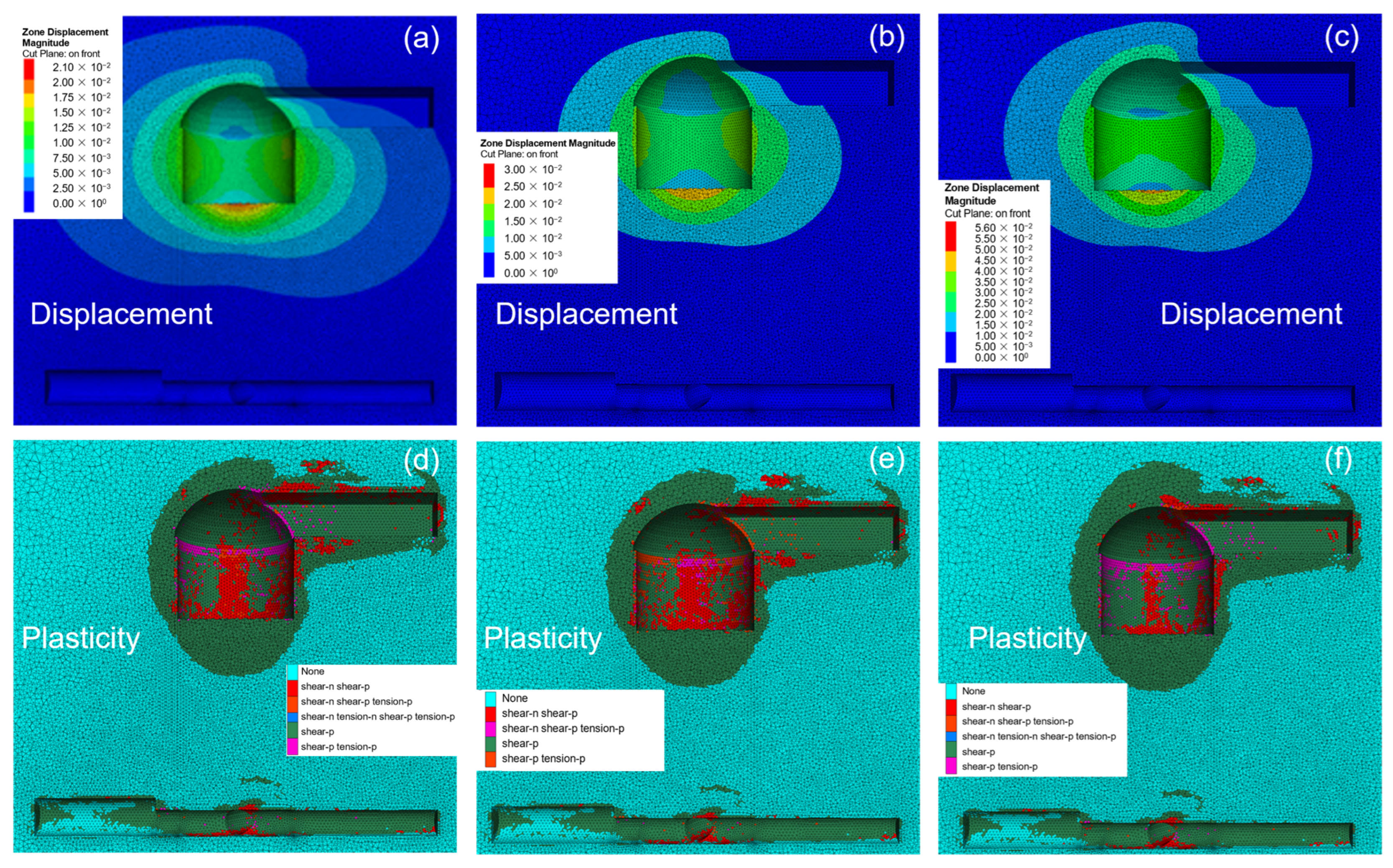
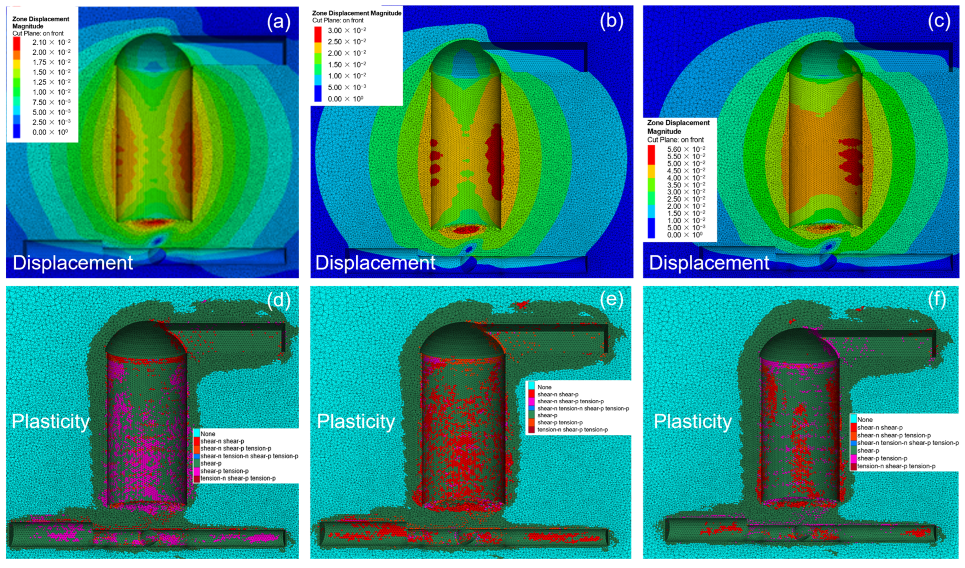
5.1. Comparative Analysis of Surrounding Rock Displacement of Water Diversion Surge Shaft Under Different Support Schemes
5.2. Comparative Analysis of Plastic Zone of Surrounding Rock of Water Diversion Surge Shaft Under Different Support Schemes
6. Conclusions
Author Contributions
Funding
Data Availability Statement
Acknowledgments
Conflicts of Interest
References
- Li, X.; Wang, H.; Jia, J.; Yang, C.; Hu, G.; Xue, Z. Ultimate displacement discrimination of stability and reliability analysis of surrounding rocks of tunnel and underground engineering. Rock. Soil. Mech. 2005, 26, 850–854. [Google Scholar]
- Xie, G.; Li, C.; Wang, L. Mechanical characteristics and practical application on stress shell of roadway surrounding rock. J. China Coal Soc. 2016, 41, 2986–2992. [Google Scholar]
- Fu, Q.; Yang, J.; Gao, Y.B.; Li, C.J.; Song, H.X.; Liu, Y.X.; Wu, X. Combined blasting for protection of gob-side roadway with thick and hard roof. J. Rock. Mech. Geotech. 2024, 16, 3165–3180. [Google Scholar] [CrossRef]
- Ren, F.Q.; Zhu, C.; Karakus, M.; He, M.C. Rockburst mitigation mechanisms of pressure relief borehole and rock bolt support: Insights from granite true triaxial unloading rockburst tests. Eng. Geol. 2024, 336, 107571. [Google Scholar] [CrossRef]
- Zhu, C.; Xing, X.S.; He, M.C.; Tang, Z.C.; Xiong, F.; Ye, Z.Y.; Xu, C.S. Failure behavior and strength model of blocky rock mass with and without rockbolts. Int. J. Min. Sci. Technol. 2024, 34, 747–762. [Google Scholar] [CrossRef]
- Xu, C.; Ren, Q.; Li, R. Entropy catastrophe criterion of surrounding rock stability. Chin. J. Rock. Mech. Eng. 2004, 23, 1992–1995. [Google Scholar]
- Zhao, S.J.; Zhang, Q.; Miao, Y.S.; Zhang, W.Z.; Zhao, X.B.; Xu, W. Sub-Homogeneous peridynamic model for fracture and failure analysis of roadway surrounding rock. Cmes-Comp. Model. Eng. 2024, 139, 3167–3187. [Google Scholar] [CrossRef]
- Zhou, P.; Shen, Y.; Zhao, J.; Zhang, X.; Gao, B.; Zhu, S. Research on disaster-induced mechanism of tunnels with steeply dipping phyllite strata based on an improved ubiquitous-joint constitutive model. Chin. J. Rock. Mech. Eng. 2019, 38, 1870–1883. [Google Scholar]
- Cheng, Q.; Guo, X. Study on comprehensive selection of mechanical parameters of rock mass in deep-buried tunnel anchor. Chin. J. Undergr. Space Eng. 2021, 17, 479–487. [Google Scholar]
- Gao, M.; Ye, S.; Yang, B.; Liu, Y.; Li, J.; Liu, J.; Xie, H. Progress in research on deep in situ rock mechanics. Bull. Natl. Nat. Sci. Found. China 2021, 35, 895–903. [Google Scholar]
- Xu, J.C.; Yang, C.B. Probabilistic back analysis based on adam, bayesian and multi-output gaussian process for deep soft-rock tunnel. Rock Mech. Rock Eng. 2023, 56, 6843–6853. [Google Scholar] [CrossRef]
- Sun, J.L.; Wu, S.C.; Wang, H.; Wang, T.; Geng, X.J.; Zhang, Y.J. Inversion of surrounding rock mechanical parameters in a soft rock tunnel based on a hybrid model eo-lightGBM. Rock. Mech. Rock. Eng. 2023, 56, 6691–6707. [Google Scholar] [CrossRef]
- Peng, Z.; Wang, Z.; Hong, C.; Li, K.; Li, A. Influence of parameter uncertainty on stability of underground water-sealed cavern. J. Shandong Univ. Eng. Sci. 2024, 54, 126–135. [Google Scholar]
- Li, S.B.; Zhang, Y.G.; Cao, M.Y.; Wang, Z.N. Study on excavation sequence of pilot tunnels for a rectangular tunnel using numerical simulation and field monitoring method. Rock. Mech. Rock. Eng. 2022, 55, 3507–3523. [Google Scholar] [CrossRef]
- Luo, Y.B.; Chen, J.X.; Chen, Y.; Diao, P.S.; Qiao, X. Longitudinal deformation profile of a tunnel in weak rock mass by using the back analysis method. Tunn. Undergr. Sp. Tech. 2018, 71, 478–493. [Google Scholar] [CrossRef]
- Qin, S.L.; Zhao, X.D.; Song, J.Y.; Wang, C. Mechanical mechanism and theoretical analysis of anchor net support based on model test and numerical simulation. Geomat. Nat. Haz Risk 2024, 15, 2350484. [Google Scholar] [CrossRef]
- Li, H.B.; Pan, W.P.; Hua, X.Z.; Luan, B.; Huang, Z.J. Instability characteristics of surrounding rock and surrounding rock control technology of deep coal roadway crossing the fault: A case study of Zhuxianzhuang coal mine. Geomat. Nat. Haz Risk 2024, 15, 2366376. [Google Scholar] [CrossRef]
- Zhu, C.; He, M.C.; Karakus, M.; Zhang, X.H.; Tao, Z.G. Numerical simulations of the failure process of anaclinal slope physical model and control mechanism of negative Poisson’s ratio cable. Bull. Eng. Geol. Environ. 2021, 80, 3365–3380. [Google Scholar] [CrossRef]
- Zhang, J.L.; Mei, M.; Wang, J.; Shang, G.P.; Hu, X.F.; Yan, J.; Fang, Q.; Plebankiewicz, E. The construction and application of a deep learning-based primary support deformation prediction model for large cross-section tunnels. Appl. Sci. 2024, 14, 912. [Google Scholar] [CrossRef]
- Liu, L.; Li, T.B.; Ma, C.C. Research on 3D geological modeling method based on deep neural networks for drilling data. Appl. Sci-Basel. 2024, 14, 423. [Google Scholar] [CrossRef]
- Mei, H.; Wang, Q.Y.; Yu, L.; Zeng, Q. A deep learning-based algorithm for intelligent prediction of adverse geologic bodies in tunnels. Meas. Sci. Technol. 2024, 35, 096119. [Google Scholar] [CrossRef]
- Zhang, J.W.; Han, S.; Li, M.C.; Li, H.; Zhao, W.C.; Wang, J.; Liang, H. CasMDN: A deep learning-based multivariate distribution modelling approach and its application in geotechnical engineering. Comput. Geotech. 2024, 168, 106164. [Google Scholar] [CrossRef]
- Zhou, Z.Q.; Bai, S.S.; Chu, K.W.; Li, J.L.; Sun, J.W.; Wang, M.X.; Sun, Y.; Li, M.H.; Liu, Y.H. Calibration of DEM macro and micro parameters via XGBoost method. Granul. Matter. 2022, 24, 106. [Google Scholar] [CrossRef]
- Yang, W.; Zhang, Q.; Li, S.; Wang, G.; Li, Y. Application of particle swarm optimization in time-dependent parameters inversion. J. Cent. South Univ. Sci. Technol. 2013, 44, 282–288. [Google Scholar]
- Ruan, Y.; Gao, C.; Liu, K.; Jia, R.; Ding, H. Inversion of rock and soil mechanics parameters based on particle swarm optimization wavelet support vector machine. Rock Soil. Mech. 2019, 40, 3662–3669. [Google Scholar]
- Ling, T.; Qin, J.; Song, Q.; Hua, F. Intelligent displacement back-analysis based on improved particle swarm optimization and neural network and its application. J. Railw. Sci. Eng. 2020, 17, 2181–2190. [Google Scholar]
- Chen, L.; Meng, J.D.; Li, Z.Z.; Xu, X.J.; Hao, L.; Ren, Y.X.; Zhao, Y. An optimized observation system and inversion method for fault detection based on surface-wave while tunneling. J. Appl. Geophys. 2024, 228, 105472. [Google Scholar] [CrossRef]
- Wang, F.; Li, X.; Miao, L.; Xu, P. Mechanical parameters identification of surrounding rock based on wavelet SVM. J. Hydroelectr. Eng. 2010, 29, 184–190. [Google Scholar]
- Kovacevic, M.S.; Bacic, M.; Gavin, K.; Stipanovic, I. Assessment of long-term deformation of a tunnel in soft rock by utilizing particle swarm optimized neural network. Tunn. Undergr. Sp. Tech. 2021, 110, 103838. [Google Scholar] [CrossRef]
- Ma, J.J.; Li, T.B.; Yang, G.; Dai, K.K.; Ma, C.C.; Tang, H.; Wang, G.W.; Wang, J.F.; Xiao, B.; Meng, L.B. A real-time intelligent classification model using machine learning for tunnel surrounding rock and its application. Georisk 2023, 17, 148–168. [Google Scholar] [CrossRef]
- Wei, W.; Jia, Y.; Sheng, Y.; Xu, G.; Yang, Y.; Zhang, D. Research on landslide susceptibility evaluation model based on I, SVM and I-SVM. Saf. Environ. Eng. 2023, 30, 136–144. [Google Scholar]
- Zhang, Y.; Su, G.S.; Li, Y.; Wei, M.D.; Liu, B.C. Displacement back-analysis of rock mass parameters for underground caverns using a novel intelligent optimization method. Int. J. Geomech. 2020, 20, 04020035. [Google Scholar] [CrossRef]
- Yan, H.H.; Liu, K.Y.; Xu, C.; Zheng, W.B. A novel method for identifying geomechanical parameters of rock masses based on a PSO and improved GPR hybrid algorithm. Sci. Rep. 2022, 12, 5670. [Google Scholar] [CrossRef]
- Shen, Y.; Guo, B.; Gu, T. Particle swarm optimization algorithm and comparison with genetic algorithm. J. Univ. Electron. Sci. Technol. China 2005, 34, 696–699. [Google Scholar]
- Kennedy, J.; Eberhart, R.C. Particle swarm optimization. In Proceedings of the IEEE International Conference on Neural Networks (ICNN 95), Perth, Australia, 27 November–1 December 1995. [Google Scholar]
- Tang, J.; Liu, G.; Pan, Q.T. A review on representative swarm intelligence algorithms for solving optimization problems: Applications and trends. IEEE-CAA. J. Automatic. 2021, 8, 1627–1643. [Google Scholar] [CrossRef]
- Jiang, A.N.; Wang, S.Y.; Tang, S.L. Feedback analysis of tunnel construction using a hybrid arithmetic based on Support Vector Machine and Particle Swarm Optimisation. Autom. Constr. 2011, 20, 482–489. [Google Scholar] [CrossRef]
- Cortes, C.; Vapnik, V. Support-vector networks. Mach. Learn. 1995, 20, 273–297. [Google Scholar] [CrossRef]
- Zhou, S.T.; Zhang, Z.X.; Luo, X.D.; Huang, Y.F.; Yu, Z.; Yang, X.W. Predicting dynamic compressive strength of frozen-thawed rocks by characteristic impedance and data-driven methods. J. Rock Mech. Geotech. 2024, 16, 2591–2606. [Google Scholar] [CrossRef]
- Huang, Y.F.; Lei, Y.; Luo, X.D.; Fu, C. Prediction of compressive strength of rice husk ash concrete: A comparison of different metaheuristic algorithms for optimizing support vector regression. Case Stud. Constr. Mat. 2023, 18, e02201. [Google Scholar] [CrossRef]
- Huang, Y.F.; Zhou, Z.K.; Li, M.Y.; Luo, X.D. Prediction of ground vibration induced by rock blasting based on optimized support vector regression models. Cmes-Comp. Model. Eng. 2024, 139, 3147–3165. [Google Scholar] [CrossRef]
- Ran, Z.; Wu, J.X. Common energy decay indices of Saint-Venant’s principle. J. Eng. Mech. 2008, 25, 14. [Google Scholar]


| Experiment Number | Elastic Modulus (GPa) | Internal Friction Angle (°) | Cohesive Force (MPa) | Maximum Deflection (mm) |
|---|---|---|---|---|
| 0 | 20 | 45 | 3 | 4.73 |
| 1 | 15 | 35 | 2.5 | 5.41 |
| 2 | 20 | 40 | 3 | 4.5 |
| 3 | 25 | 45 | 3.5 | 3.11 |
| 4 | 15 | 40 | 3.5 | 5.69 |
| 5 | 20 | 45 | 2.5 | 5.01 |
| 6 | 25 | 35 | 3 | 3.22 |
| 7 | 15 | 45 | 3 | 5.22 |
| 8 | 20 | 35 | 3.5 | 4.17 |
| 9 | 25 | 40 | 2.5 | 3.8 |
Disclaimer/Publisher’s Note: The statements, opinions and data contained in all publications are solely those of the individual author(s) and contributor(s) and not of MDPI and/or the editor(s). MDPI and/or the editor(s) disclaim responsibility for any injury to people or property resulting from any ideas, methods, instructions or products referred to in the content. |
© 2024 by the authors. Licensee MDPI, Basel, Switzerland. This article is an open access article distributed under the terms and conditions of the Creative Commons Attribution (CC BY) license (https://creativecommons.org/licenses/by/4.0/).
Share and Cite
Zou, X.-W.; Zhou, T.; Li, G.; Hu, Y.; Deng, B.; Yang, T. Intelligent Inversion Analysis of Surrounding Rock Parameters and Deformation Characteristics of a Water Diversion Surge Shaft. Designs 2024, 8, 116. https://doi.org/10.3390/designs8060116
Zou X-W, Zhou T, Li G, Hu Y, Deng B, Yang T. Intelligent Inversion Analysis of Surrounding Rock Parameters and Deformation Characteristics of a Water Diversion Surge Shaft. Designs. 2024; 8(6):116. https://doi.org/10.3390/designs8060116
Chicago/Turabian StyleZou, Xing-Wei, Tao Zhou, Gan Li, Yu Hu, Bo Deng, and Tao Yang. 2024. "Intelligent Inversion Analysis of Surrounding Rock Parameters and Deformation Characteristics of a Water Diversion Surge Shaft" Designs 8, no. 6: 116. https://doi.org/10.3390/designs8060116
APA StyleZou, X.-W., Zhou, T., Li, G., Hu, Y., Deng, B., & Yang, T. (2024). Intelligent Inversion Analysis of Surrounding Rock Parameters and Deformation Characteristics of a Water Diversion Surge Shaft. Designs, 8(6), 116. https://doi.org/10.3390/designs8060116