Abstract
The present paper is devoted to the seismic design of steel frames constituted by multistep I-shaped cross-section beam elements. The proposed design problem formulation is aimed at protecting the connections among beams and columns. In particular, reference is made to beams welded at their ends to appropriate steel plates connected by bolts to the columns. Therefore, the protection against brittle failure of the beam end sections is ensured by appropriate constraints of the optimal design problem. A useful comparison is made between the adoption of the so-called Reduced Beam Sections (RBS) and the use of multistep beam elements. In particular, the RBS approach here considered is the well-known dogbone technique consisting of reducing the width of the beam cross-sections in correspondence with suitably located beam portions, while the typical multistep beam element is constituted by a factory-made I-shaped uniform piecewise profile. To perform the necessary comparison, reference is made to a three-story, two-span plane steel frame constituted by elastic, perfectly plastic material and subjected to static and seismic loads. The load conditions and the relevant combinations have been imposed in compliance with the Italian structural code. The frame is first studied as constituted by European standard steel profiles on sale, and the related design is obtained using the optimization tool contained in SAP2000 software. A linear dynamic analysis is performed to determine the response of the frame. Later, the same frame, either equipped with dogbone and constituted by multistep beam elements, subjected to serviceability load conditions, is studied in terms of inter-story drifts and beam deflections. The geometry of the multistep beam elements is obtained by the solution to the proposed optimization problem. Furthermore, a nonlinear static analysis is performed to evaluate the capacity curves of the same frames. The results obtained for the frames equipped with the described different devices, compared with those related to the original frame, provide very interesting information on the sensitivity of the seismic response of the structure, showing the full reliability of the multistep beam element approach.
1. Introduction
The wide selection of frame structures to be adopted in both civil and industrial buildings allows the design of structural elements of different typologies, constituted by standard or innovative materials, considering the use of suitable specific devices to improve the local or global behavior, achieving a safer structure with higher performance.
The most commonly adopted structural typologies are the trusses and the flexural frames, whose selection strongly depends on the structural geometry and on the acting loadings. It is worth noting that, often in frame structures, the two typologies are both present.
From the material point of view, the designer has a wide range of choices. In the last century, reinforced concrete has been widely adopted due to its intrinsic simple production and implementation. This wide adoption brings many drawbacks, mainly related to actual environmental sustainability standards and to its durability related to weathering. Indeed, as it is well known, ordinary Portland cement in concrete construction has led to significant environmental concerns, like depletion of natural resources and CO2 emissions in its production process. Furthermore, practical experience with concrete structures widely shows they suffered material decay during their service life due to natural actions, especially related to steel oxidation. Several studies have been proposed to enhance the environmental performance of concrete structures, as well as their durability (see, e.g., [1]).
In recent years, interesting research has been devoted to new conglomerates with mechanical performances analogous to those of Ordinary Portland Cement (OPC) concrete, but they are characterized by strong environmental sustainability and show a very important role in the circular economy of construction. The most studied new conglomerate is based on geopolymers [2,3,4], which are materials developed from alumino-silicate source materials (usually fly ash or slag) with alkaline activators and natural materials such as Kaolinite clay. As reported in many research papers, the mechanical characteristics of such materials can be improved by a suitable adoption of artificial or natural fibers [5,6,7,8,9]. Another important construction material not commonly adopted is wood, which shows high environmental sustainability aspects but whose use is limited to very simple structures.
The second most common structural material widely adopted worldwide is steel. It shows high mechanical performances and limited drawbacks in terms of environmental sustainability; it fulfills the circular economy criteria and guarantees long durability (see, e.g., [10]). Finally, the actual steel production in highly qualified factories ensures high ductility characteristics that are in perfect agreement with the requirements of international standards, especially in the case of structures under dynamic loadings. Furthermore, steel structures provide cost-effective constructions, increased usable floor space, aesthetic pleasing, future adaptability, ease of design, and green production.
In the present paper reference is made to steel frame structures which have been the topic of a huge amount of research devoted both to the analysis [11,12,13,14,15,16,17] and to the optimal design problems [18,19,20,21,22,23,24]. In particular, the focus is on moment resisting steel frame equipped with devices able to improve the seismic behavior, with a specific attention paid to the Reduced Beam Sections (RBS) connections and to the adoption of multistep beam elements.
The benefit of equipping the frame with such devices is to obtain a structure that fulfills the requirements of the reference standard, taking simultaneously advantage of their intrinsic mechanical characteristics. Briefly, the standard requirements [25,26] can be summarized as follows: (a) to possess suitable stiffness and resistance both in serviceability limit state (SLS) and in ultimate limit state (ULS) conditions; (b) to exhibit appropriate plastic dissipation under high-intensity seismic loadings; (c) to avoid brittle ruptures, especially in correspondence of the welded connections.
Therefore, an important role is played by the connections among structural elements, which must guarantee specific performances in terms of safety, stiffness, and resistance and deeply influence the global behavior of the structure. Usually, these connections are made by welding and/or bolting the ends of the involved elements. It is worth noting that some recent seismic events, for example, the Northridge earthquake of 1994, evidenced the vulnerability of the welding connections [27,28,29], showing that the failure of the connections was due to the brittle behavior of the welding.
In practical engineering, the main solution utilized to face this problem is the realization of RBS connections. One of the most popular and appropriate RBS connections is represented by the dogbone technique [30,31,32,33,34,35,36,37,38,39,40], which mainly consists of a suitable cut of the flanges of the I-shape profile adopted for the beam aimed to determine a prefixed reduction of the resistance of the specific portion of the element where it is operated. The shape of the cut, symmetrically made with respect to the web of the profile, could be linear as well as parabolic. This technique concentrates the localization of the plastic hinge in a specific portion, but, for obvious reasons, it implies a non-negligible local flexural stiffness decrement, which affects even the overall stiffness of the frame. Other solutions were proposed by different authors [41,42,43,44,45,46,47,48,49,50,51,52,53,54,55,56,57,58,59,60], ranging from the use of special treatments on the beam elements to the adoption of special devices where a resistance reduction is imposed, identifying a special section devoted to the localization of plastic deformations.
In the framework of the RBS connections, some of the authors proposed a new special device called the Limited Resistance Plastic Device (LRPD), which is characterized by the advantages of the RBS connections and enhanced stiffness features. The main novelty of LRPD, whose positioning is typically at the end of beams and/or at the column base, is that its specific design allows the onset of plastic strain, always guaranteeing the unaltered bending stiffness of the overall involved structural element.
The first model of LRPD was referred to as Limited Resistance rigid Perfectly plastic flexural Hinges (LRPH) [61,62,63]; in subsequent studies, the design problem has been extended to consider both normal and tangential stresses acting simultaneously, taking advantage of smart beam elements to calculate the mechanical response of the beam elements [64]. Further studies have been devoted to the validation of the LRPD by numerical FE analyses and by appropriate experimental tests, and suitable applications have been devoted to the design of frames with assigned capacity curves [65]. Furthermore, the authors proposed many improvements in the formulation of the LRPD, comparing the results with those obtained by different RBS connections, considering the local buckling, and protecting the welded section from brittle rupture (see, e.g., [66]).
The actual version, referred to as LRPD, is a beam element with multistep geometry, constituted by three subsequent I-shaped portions whose width, depth, web, and flange thicknesses are suitably designed.
In this last version of LRPD, the inner portion with reduced dimensions shows limited strength and allows the onset of plastic strain, while the outer portions are equal to each other and show web and flange thicknesses greater to guarantee the unaltered bending stiffness of the overall involved element. As it can be easily deduced, LRPD design requires the solution to appropriate optimal design problems and their production must be factory performed by welding steel plates of assigned thickness.
It must be remarked that the use of LRPD requires specific factory manufacturing to realize the whole structural element constituted by the central portion (standard profile) and by the end portions (LRPD).
It follows that it can be very useful to extend the fundamental idea at the basis of LRPD to the entire structural element by defining a multistep beam constituted by welded I-shaped cross-sections suitably designed to fulfill all the above-described standard requirements. These beams are constituted by a given number of consecutive portions, each with a constant section. Generally speaking, the cross-sections of different portions show different geometric characteristics (in terms of width, depth, web, and flange thickness) that must be suitably designed to represent the main design variables. The length of each portion, as well as its position along the structural element, can represent further design variables.
The aim of the present paper is to propose a new special formulation of the optimal design problem of multistep beam elements, mainly devoted to the comparison between the structural performances of frames equipped with dogbones and with this new kind of structural beam. The presence of dogbones defines a structural element subdivided into five consecutive portions where the first, the third, and the fifth ones possess the same cross-section of the original element, while the second and fourth ones are equal to each other, are positioned symmetrically with respect to the middle cross-section of the reference beam element, possess an assigned length, and show a reduced cross-section variable along the beam axis due to the analogous cut of the flanges. Consequently, the multistep beam is designed to consist of five consecutive portions whose length is equal to the corresponding portion of the beam equipped with the dogbones. The first, third, and fifth portions possess the same constant cross-section with flange thickness obtained by the solution to the proposed optimal design problem. The second and the fourth portions (equal to each other) possess reduced geometric characteristics (in terms of flange width and flange thickness), which are always obtained by the solution to the optimal design problem. Finally, it is assumed that the web thickness of all the portions of the multistep beam is always the same and that the flanges of all portions possess a unique common medium plane.
To compare the different approaches described above, reference is made to a standard steel frame under both static and seismic loadings. The reference frame is first designed following the standard requirements [26], adopting European standard I-shaped steel profiles on sale, and its structural response is determined. The obtained reference frame is successively equipped with dogbones designed following the reference standard [25,67] utilizing two different dogbone sizing. The two obtained frames are studied, and their structural response is also determined. Similarly, just like was performed for the dogbone frames, two multistep beam frames are designed by solving the proposed optimal design problem, imposing that each cross-section of the weak portions of each beam of the typical frame exhibits the same flexural strength as the corresponding dogbone, while the strong portion cross-sections are designed in such a way that the overall element fulfills the above-described safety, strength, and stiffness requirements. Therefore, the proposed optimal design problem formulation for multistep beam element frames represents an interesting enhancement of the classical design problem formulation for steel structures, allowing a wider degree of freedom in the cross-section sizing and in the definition of their strength and stiffness features.
The proposed numerical application shows the great affordability of the proposed approach representing a first step for further deeper developments devoted to the overall optimal design of a frame equipped with multistep beam elements.
2. Geometry and Mechanical Properties of the Different Approaches
In this section, a description of the geometrical and mechanical behavior of the dogbone and of the proposed multistep beam element is provided. In both cases, it is possible to realize a specific portion of the beam element with reduced yield resistance, where the onset of plastic deformations is expected, but only the multistep beam element ensures appropriate characteristics of resistance and stiffness of the connections between beams and columns, as it will be proved in the following.
In Figure 1, the main geometric characteristics of the dogbone are reported.
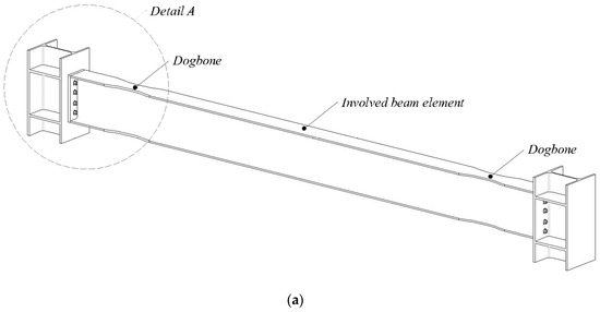
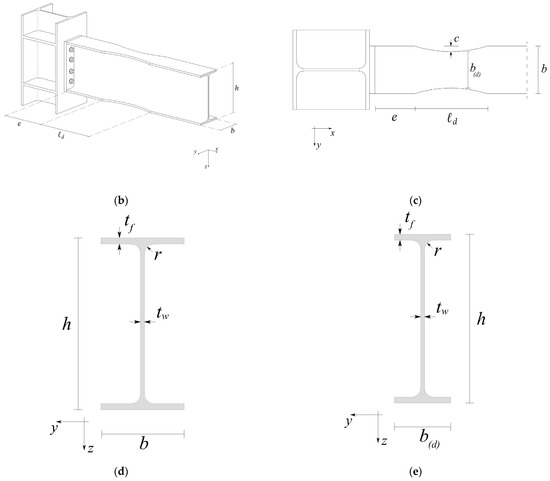
Figure 1.
Dogbone geometry; (a) 3D sketch of the beam element equipped with dogbones; (b) Detail A with main geometrical features; (c) typical cut geometry; (d) typical geometry of the reference beam cross-section; (e) typical geometry of the dogbone middle cross-section.
In Figure 1a, a 3D representation of a typical beam element with the dogbone insertions is sketched. In Figure 1b, a detail of the connection with dogbone is represented; here, and are the width and depth of the involved I-shaped beam element (reference beam cross-section reported in Figure 1d, the parameter indicates the distance between the initial cut section and the relevant column where the beam end is connected and measures the length of the portion with reduced variable width. Among the different shapes available for cutting the flanges, the parabolic one is chosen in the present study. As reported in Figure 1c,e, the middle cut section (i.e., the weaker cross-section) shows the minimum base length , where is usually defined as percentage of the original beam width and it represents the main parameter for the dogbone sizing. It is worth noting that the parameters and usually depend on the depth of the original beam width, as will be specified in the application stage. Due to the assigned geometry of the dogbone, for a given , it is possible to determine the corresponding geometric and mechanical resistance parameters as well as the related elastic and plastic axial forces and bending moments of the weaker cross-section, i.e., the one located in the middle of the interested portion and reported in Figure 1e, as follows:
where, besides the already defined quantities, is the area of the cross-section; , , and are web thickness, flange thickness, and welding radius of the involved cross-section beam element; is the second-order moment of area of the cross-section with respect to the central axis ; and are the elastic and plastic resistance moduli of the cross-section, respectively; and are the limit elastic and plastic axial forces (equal to each other); and, finally, and are the limit elastic and plastic bending moments of the cross-section. It is assumed that the material constituting the beam element shows elastic, perfectly plastic behavior, and, as usual, the tensile yield stress has been indicated with .
While the dogbone technique consists of direct intervention and modification on the extreme portions of the original beams of the frame, the use of multistep beams consists of the complete replacement of the original beams with the factory-made I-shaped multistep ones. For the aim of the present study, the typical multistep beam here is considered to consist of five subsequent portions with uniform piecewise I-shaped cross-sections, as reported in Figure 2.

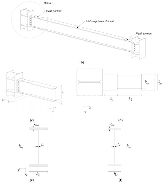
Figure 2.
Multistep beam geometry: (a) typical multistep beam element constituted by five subsequent portions; (b) 3D sketch of the multistep beam; (c) Detail A with main geometrical features; (d) view of the beam extrados with main geometrical features; (e) typical geometry of the strong cross-section; (f) typical geometry of the weak cross-section.
Referring to an analogous scheme as for the beam element equipped with dogbones, portions 2 and 4 are constituted by equal cross-sections, as well as portions 1, 3, and 5 are constituted by equal cross-sections (but different from those of portions 2 and 4). Portions 2 and 4 represent the weak portions of the multistep beam, while portions 1, 3, and 5 represent the strong portions of the multistep beam. In the following, all the quantities related to the weak portions will be identified by the index , while the analogous quantities related to the strong portions will be identified by the index .
Furthermore, the length of the weak portions 2 and 4 is usually assumed the same as well as it happens for portions 1 and 5. To design these lengths, different approaches can be utilized. Referring to the weak portions, as already stated, the main objective is to create a zone where a fully plasticization can occur. As proved in [64], this requirement can be satisfied by choosing the weak portion length not less than . On the other hand, referring to the strong portion length (1 and 5), the corresponding length can be defined, imposing both resistance and mechanical (stiffness) constraints in the relevant optimization problem (see, e.g., [61,62,63]). In the present paper, due to the main aim related to the comparison between dogbone and multistep beam, the following relations will be adopted as follows:
Furthermore, the consecutive I-shape elements with different flange and web thicknesses are symmetrically disposed with respect to the medium cross plane (Figure 2e,f). From a geometrical point of view, it is assumed that (a) the flanges of all the portions possess a unique common medium plane as well as the webs; (b) always referring to the dogbone scheme, the webs of all the cross-section portions possess the same thickness equal to that of the original cross-section beam element. From a mechanical point of view, in order to guarantee the desired behavior, the strong portions must possess flange thicknesses greater than the corresponding ones of the weak portions.
The geometric and mechanical resistance parameters, as well as the related elastic, are applied to all the quantities referred to in the relevant cross-section as follows:
where, besides the already defined quantities, is the area of the cross-section, , and are width, depth and flange thickness of the cross-section, is the second-order moment of area of the cross-section with respect to the central axis , and are the elastic and plastic resistance moduli of the cross-section, respectively, and are the limit elastic and plastic axial forces (equal to each other) and, finally, and are the limit elastic and plastic bending moments of the cross-section.
Since the multistep beam is constituted by welded I-shaped cross-sections, in Equations (11)–(17) the welding size has been neglected. Analogous relations can be written for the cross-sections related to the strong portions, changing index with index .
3. Design Criterion for the Multistep Beam
As previously stated, steel structures are often more advisable with respect to other typologies. Their full reliability is related to the capacity of fulfilling some appropriate fundamental requisites: they must possess adequate resistance and stiffness features both in serviceability and in ultimate limit conditions, must exhibit wide plastic dissipation capacity and the risk of brittle failure must be avoided in correspondence of the welded connections. It follows that the introduction of special devices in the structural elements (dogbone) can be very useful, as well as the design of special factory-made beam elements (multistep beams).
Before facing the design of the multistep beams, the following remarks can be useful. As clarified in the introduction, according to [67], where the allowed geometric characteristics and ranges are reported, the design of the dogbone does not require any specific computational procedure or numerical effort. Specifically, both the distance between the end section of the beam and the initial section of the dogbone, and the length of the dogbone itself depend on the depth of the original cross-section, and the allowable ranges are and .
An analysis of the structural effects due to the dogbones (see, e.g., [68]) immediately reveals that their application does not fulfill all the above-described requirements. Indeed, as it is also reported in the referenced standard [67], the dogbones implicate a reduction of the overall stiffness of the beam, and, further, their design does not take into account the stresses acting in the welded section to avoid dangerous brittle ruptures.
It is worth noting that brittle ruptures represent a very dangerous limit state identifying an overall structural behavior inappropriate for a steel structure, which must be characterized by a ductility behavior, as the international structural standards requires throughout the adoption of a suitable behavioral factor.
The design of the multistep beam, both regarding the geometry of the cross-section and the length of each portion, requires the solution of an optimal design (usually, the objective function is the minimum volume) with suitable constraints on stiffness, strength, and safety.
In the present paper, the multistep beam is designed by means of a simplified procedure, reported in the following, starting from some assigned dimensions to achieve a meaningful comparison with the dogbones.
First, the minimum volume is assumed to be the objective function of the multistep beam. The following geometrical characteristics are assumed:
- as the limit contour of the cross-section, the rectangle circumscribed to the section of the original beam is selected; clearly, this rectangle is characterized by a base and a depth equal to the width and to the depth of the original beam;
- the length of each portion is assumed as reported in Equations (8)–(10);
- all the cross-sections possess the same web thickness equal to that of the original beam, that is , and the flanges of all the portions possess a unique common medium plane;
- the width of the cross-section of the strong portions is assumed to be equal to that of the cross-section of the original beam, that is while that of the weak portion is deduced by the solution to the optimization problem.
Therefore, the variables of the optimal design problem are the width and the thicknesses and .
The constraints to be imposed are related to the following requirements:
- the limit plastic bending moment of the weak portions is equal to that of the dogbone;
- the cross-section of the weak portion has to belong to Class 1 of [25], avoiding any possible local buckling phenomenon;
- the limit elastic bending moment of the cross-section characterizing the strong portions must be such to prevent brittle failure;
- the bending stiffness of the overall multistep beam must not be lower than that of the original beam.
The fulfillment of the above-reported requirements leads to a multistep beam possessing adequate strength and ductility features, avoiding any reduction of the bending stiffness and limiting the stresses acting in the welded section.
It is worth noting that, with the above-described characteristics of the multistep beam, the use of the behavioral factor as reported in the structural standards is fully effective.
Therefore, the minimum volume design problem for the multistep beam is characterized by the following assigned quantities:
- , and (lengths of the different portions of the multistep beam);
- (cross-section widths of the strong portions of the multistep beam, being the width of the original beam element);
- (cross-section depths of the strong portions of the multistep beam, being the depth of the original beam element);
- (web thickness of the different portions of the multistep beam, being the web thickness of the original beam element);
- (material yield stress);
It is also characterized by the following geometrical and technological constraints:
- (the cross-section flanges of subsequent beam element portions have the same medium plane);
by the following design variables:
- (width of the weak portion cross-sections of the multistep beam);
- (flange thickness of the weak portion cross-sections of the multistep beam);
- (flange thickness of the strong portion cross-sections of the multistep beam);
and by the following objective function (volume of the multistep beam)
Therefore, the above-described minimum volume design problem for the multistep beam can be written in the following form:
subjected to:
where Equation (20) provides the upper and lower bound on the width of the weak portion cross-section, Equations (21) and (22) provide the upper and lower bounds on the flange thicknesses of the weak and strong portion cross-sections, respectively, Equation (23) provide the constraint imposing that the weak portion cross-section belongs to the Class 1, Equation (24) ensures that the weak portion cross-section reaches the yield bending moment value as the related weaker dogbone cross-section, Equation (25) ensures that the strong portion cross-section, which realizes the welded connection, is safe against any brittle failure (being its limit elastic bending moment not lower than the maximum envelop bending moment acting on the relevant section) and, finally, Equation (26) ensures that the global flexural stiffness of the multistep beam element is not lower than the corresponding one related to the original beam element, being the second-order moment of area of the original cross-section beam element.
Equations (20)–(22) represent trivial technological and mechanical constraints, Equation (23) is deduced by well-known formulae present in the international structural codes, Equation (24) relates the plastic resistance modulus of the middle dogbone cross-section (first member of the inequality) and the plastic resistance modulus of the weak portion cross-section (second member of the inequality), in Equation (25) the limit elastic bending moment of the strong portion cross-section, which realizes the welded connection, is expressed in terms of elastic resistance modulus. Finally, Equation (26) is deduced imposing that the global flexural stiffness of the multistep beam element is not lower than the corresponding one related to the original beam element, i.e., that the relative rotation of the end cross-sections of the multistep beam element is not greater than the analogous quantity related to the original beam element. With reference to Figure 3, the equality condition related to this last constraint reads as follows:
that, with easy mathematics, can be written as follows:
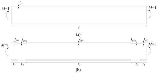
Figure 3.
Load scheme related to the global stiffness constraint: (a) Reference beam element subjected to uniform unitary bending moment; (b) multistep beam subjected to uniform unitary bending moment.
4. Numerical Application
As a numerical application, a perfectly clamped three-story two-span plane steel frame is considered. In Figure 4 the axis scheme of the reference frame is sketched and in Table 1 the assigned geometry is detailed.
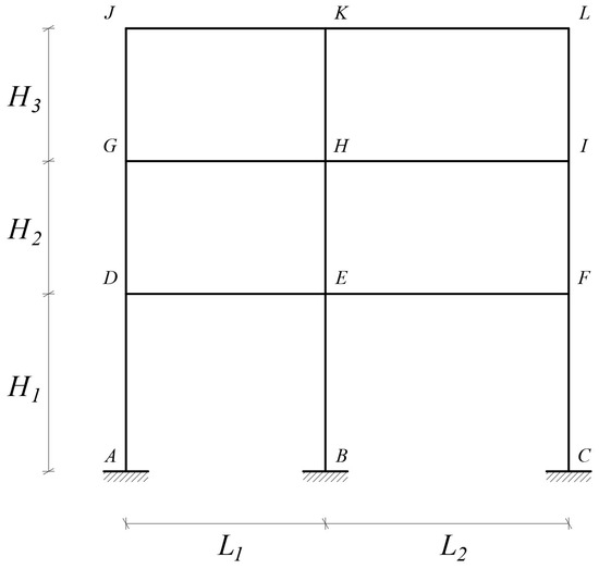
Figure 4.
Axis scheme of the reference plane steel frame.

Table 1.
Geometrical characteristics of the reference frame.
The material is assumed to be S275 steel with an elastic-perfectly plastic behavior. The load condition, referring to the Italian structural code [26], is defined by the presence of the structure self-weight , of the permanent loads and of the variable loads . It is assumed that these actions produce uniformly distributed loads on the beams with the values reported in Table 2.

Table 2.
Values of the acting loads on the selected frame.
For the aims of the present study and for the sake of simplicity, it is assumed that all the beams are subjected to the same uniformly distributed load combinations, whose values depend on appropriate load multipliers as indicated by the Italian code [26] and defined for the different considered limit states. The seismic actions are defined by referring to the Italian code for a building in Palermo, by assuming a class type B and a category type III. Therefore, the design of the frame is obtained considering all the load combinations as prescribed by the relevant code for serviceability and limit collapse conditions, as well as for static load and for seismic load conditions. As usual, the seismic response is obtained by the solution to a linear dynamic analysis. The structural software adopted for the numerical computations is SAP2000 v2017 [69].
The main aim of the numerical application is to verify the reliability of the proposed optimal procedure, to analyze for the given structure the effectiveness of the use of the dogbone technique and of the multistep beams, and to compare the two different interventions in terms of structural safety and consistent behavior.
Therefore, at first, the structural design of the chosen frame is carried out by performing the auto-design procedure available in SAP2000 and making reference to European standard steel profiles on sale. The obtained results (optimal cross-sections of beams and columns) are reported in Table 3.

Table 3.
Cross-sections obtained by the standard code design.
In Figure 5 the exploitation percentage of beams and columns of the designed frame is represented in terms of resistance capacity; in Table 4, for each beam end, are reported: the ratio between limit plastic bending moment and maximum value of the envelope bending moment response and the ratio between limit elastic bending moment and maximum value of the envelope bending moment response.
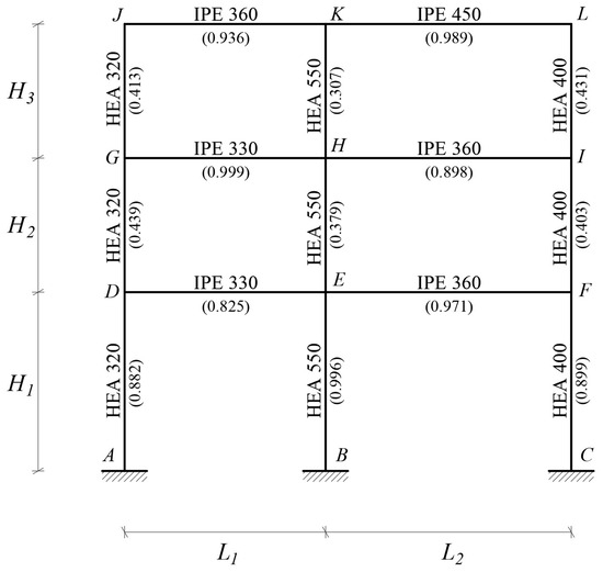
Figure 5.
Exploitation percentage of beams and columns of the reference frame.

Table 4.
The ratio between plastic/elastic bending moment and maximum envelope acting bending moment in correspondence of the beam ends of the reference frame ( left end, right end).
The examination of the results summarized in Table 4, with specific reference to the beam behavior, allows us to state that at the cross-section beam ends (where the connections between beams and columns are realized), the limit plastic safety condition is fulfilled, but in many cases (beams D-E, E-F, G-H, H-I) the limit elastic bending moment is lower than the acting one, i.e., some brittle damage can occur, and the safety is not ensured. This remark will be recalled to evaluate the goodness of the response of the frame equipped with dogbones and multistep beams.
Once the reference frame is designed, the dogbone intervention is defined.
Two different width reductions have been chosen for the dogbone intervention: (in the following indicated as DB60, ) and (in the following indicated as DB40, ). With reference to Figure 6 and Table 5, the geometry of the dogbone intervention is fully defined [67]. The dogbones have been considered to be realized at all the frame beam ends.
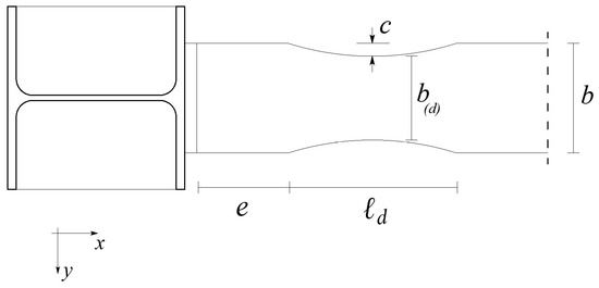
Figure 6.
Geometric characteristics of the dogbone.

Table 5.
Geometrical parameters characterizing the adopted dogbones ( is the depth of the reference cross-section).
Once the geometry of the dogbones is defined, the multistep beams can be designed. The optimal design is obtained by the solution for each beam element of the minimum volume problem (19). Assuming the length of the portions of the multistep beams as the corresponding ones of the beam equipped with dogbones, two different designs are determined, related to the two above-described different dogbone geometries considered: the first one (in the following referred to as MS60) is determined by imposing, besides the other common constraints, that the cross-sections of the weak portions of the multistep beams possess the same limit bending resistance as DB60; the second one (in the following referred to as MS40) is determined analogously but referring to the limit bending resistance of DB40. In Table 6 and Table 7, the full geometry of the cross-sections of the obtained multistep beams is reported for MS60 and MS40, respectively.

Table 6.
Geometric characteristics of the multistep beam element (MS60) in mm.

Table 7.
Geometric characteristics of the multistep beam element (MS40) in mm.
The static and the seismic (linear dynamic) analyses of the frames related to DB60 and DB40 intervention, as well as those of the frames constituted by MS60 and MS40 multistep beams, are carried out, always by using the structural software SAP2000. It is worth noting that to perform these analyses each beam has been considered as constituted by five subsequent portions with suitably assigned geometry, as deduced by the previous computations.
The comparison between the two different approaches is made analyzing the responses of the frames in serviceability conditions (limit elastic regime), in limit collapse conditions (envelope of fundamental static and seismic combinations) and beyond the elastic limit (performing a push-over analysis).
Referring to serviceability conditions, the control is made on the relevant kinematical quantities: deflection of the middle point of the beams and inter-story drifts. In Table 8 the deflections of the middle point of all the beams for the studied frames (reference frame, DB60, DB40, MS60 and MS40 frames) is reported.

Table 8.
Deflections of the beams [mm].
Even if all the results are fully acceptable in terms of structural code rule (the maximum deflection reaches about 1.2‰ of the related spam length), it is easy to observe that in all the cases, the deflections related to the dogbone frames are greater than the one of the reference frames; on the contrary, in all the cases the deflections related to the multistep beam frames are not greater than those of the reference frame.
In Figure 7, a diagram is sketched where the maximum frame inter-story drifts are reported for all the investigated frames as the percentage of the inter-story heights. Once again, all the evaluated drifts are consistent and respect the relevant structural code [26], which requires that drifts do not exceed 5‰ of the inter-story height. Nevertheless, it is worth noting that just the multistep frames ensure less global deformability, better protecting the structure against secondary element damages.
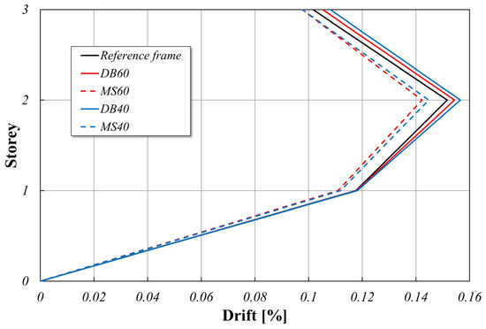
Figure 7.
Inter-story drifts.
In limit collapse conditions, the control must be carried out by comparing the cross-section capacity with the structural demand resulting from the analysis. For the aim of the present study, reference has been made to the behavior of the end cross-sections of the beams, which represent the portions mainly involved by the presence of the dogbones and of the multistep beams.
Operating as already made for the reference frame, for each beam end of the dogbone frames and of the multistep beam frames, in Table 9 is reported the ratio between limit plastic bending moment and maximum value of the envelope bending moment response.

Table 9.
The ratio between the plastic limit bending moment and maximum acting bending moment for the frames with dogbones and multistep beams ( is the left end, is the right end).
As expected, the safety is always ensured. But, as previously stated, this result can be accepted if the possibility of dangerous brittle failure is disregarded. Unfortunately, only the involved cross-sections constitute the welded connections, and, therefore, just for them, the risk of brittle failure is actual. To this aim, for each beam end of the dogbone frames and of the multistep beam frames, Table 10 reports the ratio between the limit elastic bending moment and the maximum value of the envelope bending moment response.

Table 10.
The ratio between elastic limit bending moment and maximum envelope acting bending moment for the frames with dogbones and multistep beams ( left end, right end).
The examination of these results clearly highlights that just the multistep beam frames in all the cases satisfy the check, ensuring always a linear elastic behavior and, consequently, preventing any dangerous brittle failure.
Finally, to deduce some further information on the post elastic behavior of the investigated frames, a static non-linear analysis (push-over) has been performed for all the frames. The results, referred as capacity curves, are plotted in Figure 8, where the diagrams are sketched in terms of global base shear force vs displacement of the control point (chosen as the point at the top of the frame central column).
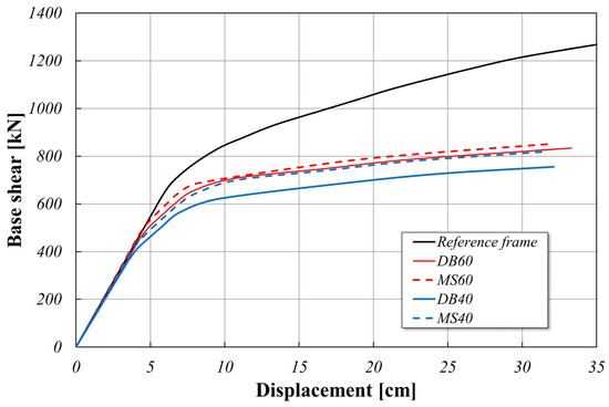
Figure 8.
Push-over curves.
The following remarks can be derived:
- all the frames show an ideal consistent behavior beyond the elastic limit, exhibiting structural stability for increasing horizontal actions. In fact, this good behavior is really exhibited if no brittle failure occurs, i.e., if the cross-sections of the beam end behave elastically. As previously proved, such good behavior is just ensured for the multistep beam frames;
- the multistep beam frames and the dogbone frames are all characterized by a comparable lower limit for the intensity of the horizontal load with respect to the reference frame due to the weakening of the relevant beams; it is worth noting that in all the cases, the resistance capacity of the multistep beam frames is greater than the one of the dogbones frames;
- all the frames exhibit an initial elastic behavior with very close stiffness values; actually, in the initial stage of loading, the frame stiffness is mainly influenced by the column stiffnesses, which are the same for all the frames. Anyway, confirming the good consistency of the multistep beam frame approach, the initial stiffness of these frames is always greater than the corresponding one related to the dogbone frames, as reported in Table 11, where the difference, in terms of percentage, of elastic initial stiffness of the reference frame with respect to that of the frames with dogbones and of the frames constituted by multistep beam elements is given.
 Table 11. Percentage difference of initial elastic stiffness of the original frame with respect to that of the frames with dogbones and of the frames constituted by multistep beam elements.
It is worth noting that the negative value deduced for MS60 indicate that the related frame exhibits an initial stiffness greater than the one of the reference frame; this result must not surprise, indeed it depends on the circumstance that for this frame the demand in term of elastic resistance (related to the brittle failure prevention) mainly influence the optimization problem with respect to the stiffness requirements.
5. Conclusions
The present paper is devoted to the proposal of a simple optimal design problem formulation for steel frames constituted by multistep I-shaped cross-section beam elements aimed at protecting the connections among beams and columns. In order to investigate the reliability of the proposed formulation and on the effectiveness of the use of the multistep beam elements. A deep comparison has been carried out among the behavior of the standard code design of a chosen three-story, two-span plane steel frame of the same frame equipped with dogbones and of the frame constituted by multistep I-shaped cross-section beam elements.
The obtained results have been definitely encouraging; indeed, it has been proved that only the frame constituted by multistep I-shaped cross-section beam elements, designed by means of the proposed formulation, ensures the fulfillment of all the required good features for the structure in terms of resistance, deformability, ductility, and safety with respect to undesired brittle failure.
The proposed formulation, therefore, represents a consistent advancement of the concept of LRPD devices belonging to the broader field of RBS devices. At the same time, the reliability of the formulation and the perfect consistency of the obtained results represent an incentive to deepen the present study. Several future developments are expected, as the proposing of more general optimal design problem formulations devoted to the search of frame steel structures constituted by multistep beam elements in which all the geometric features can represent specific design variables, always respecting all the relevant behavioral constraints, the introduction of more rigorous elastic and yield resistance domains to evaluate the structure capacity, as well as the extension to three-dimensional structures.
Furthermore, appropriate experimental tests and the related due FEM analyses will be carried out in order to verify the consistency of the adopted computational model with the realization of the factory-made I-shaped uniform piecewise profiles also from a technological point of view.
Author Contributions
Conceptualization, L.P. and S.B.; methodology, L.P.; validation, S.V. and S.B.; writing—original draft preparation, L.P. and S.B.; writing—review and editing, L.P. and S.B. All authors have read and agreed to the published version of the manuscript.
Funding
The APC was funded by FFR 2024 funds from the University of Palermo.
Institutional Review Board Statement
Not applicable.
Informed Consent Statement
Not applicable.
Data Availability Statement
Data are contained within the article.
Conflicts of Interest
The authors declare no conflicts of interest.
References
- Müller, H.S.; Haist, M.; Vogel, M. Assessment of the sustainability potential of concrete and concrete structures considering their environmental impact, performance and lifetime. Constr. Build. Mater. 2014, 67, 321–337. [Google Scholar] [CrossRef]
- Davidovits, J. Geopolymers and geopolymeric materials. J. Therm. Anal. 1989, 35, 429–441. [Google Scholar] [CrossRef]
- Arcones-Pascual, G.; Hernández-Olivares, F.; Sepulcre-Aguilar, A. Comparative properties of a lime mortar with different metakaolin and natron additions. Constr. Build. Mater. 2016, 114, 747–754. [Google Scholar] [CrossRef]
- Zhang, P.; Zheng, Y.; Wang, K.; Zhang, J. A review on properties of fresh and hardened geopolymer mortar. Compos. Part B Eng. 2018, 152, 79–95. [Google Scholar] [CrossRef]
- Lilargem Rocha, D.; Tambara Júnior, L.U.D.; Marvila, M.T.; Pereira, E.C.; Souza, D.; de Azevedo, A.R.G. A Review of the Use of Natural Fibers in Cement Composites: Concepts, Applications and Brazilian History. Polymers 2022, 14, 2043. [Google Scholar] [CrossRef]
- de Lima, T.E.S.; de Azevedo, A.R.G.; Marvila, M.T.; Candido, V.S.; Fediuk, R.; Monteiro, S.N. Potential of Using Amazon Natural Fibers to Reinforce Cementitious Composites: A Review. Polymers 2022, 14, 647. [Google Scholar] [CrossRef]
- Majumder, A.; Stochino, F.; Frattolillo, A.; Valdes, M.; Mancusi, G.; Martinelli, E. Jute fiber-reinforced mortars: Mechanical response and thermal performance. J. Build. Eng. 2023, 66, 105888. [Google Scholar] [CrossRef]
- Greco, P.F.; Pepi, C.; Gioffré, M. A novel biocomposite material for sustainable constructions: Metakaolin lime mortar and Spanish broom fibers. J. Build. Eng. 2024, 83, 108425. [Google Scholar] [CrossRef]
- Benfratello, S.; Cirello, A.; Palizzolo, L.; Sanfilippo, C.; Valenza, A. Experimental Analysis and Numerical Modelling of the Mechanical Behavior of a Sisal-Fiber-Reinforced Geopolymer. Appl. Sci. 2024, 14, 5216. [Google Scholar] [CrossRef]
- Landolfo, R.; Cascini, L.; Portioli, F. Sustainability of steel structures: Towards an integrated approach to life-time engineering design. Front. Archit. Civ. Eng. China 2011, 5, 304–314. [Google Scholar] [CrossRef]
- Gokhfeld, D.A.; Cherniavsky, D.F. Limit Analysis of Structures at Thermal Cycling; Springer: Dordrecht, The Netherland, 1980; ISBN 978-90-286-0455-1. [Google Scholar]
- Marti, K. Limit load and shakedown analysis of plastic structures under stochastic uncertainty. Comput. Methods Appl. Mech. Eng. 2008, 198, 42–51. [Google Scholar] [CrossRef]
- Chen, W.; Duan, L. Plasticity, Limit Analysis, Stability and Structural Design: An Academic Life Journey from Theory to Practice; World Scientific: Singapore, 2021; ISBN 978-981122974-9/978-981122973-2. [Google Scholar]
- Huang, M.F.; Li, Q.; Chan, C.M.; Lou, W.J.; Kwok, K.C.S.; Li, G. Performance-based design optimization of tall concrete framed structures subject to wind excitations. J. Wind. Eng. Ind. Aerodyn. 2015, 139, 70–81. [Google Scholar] [CrossRef]
- Benfratello, S.; Di Paola, M.; Palizzolo, L.; Tabbuso, P. Evaluation of the shakedown limit load multiplier for stochastic seismic actions. Meccanica 2017, 52, 2735–2750. [Google Scholar] [CrossRef]
- Zhang, R.; Wang, W.; Alam, M.S. Seismic evaluation of friction spring-based self-centering braced frames based on life-cycle cost. Earthq. Eng. Struct. Dyn. 2022, 51, 3393–3415. [Google Scholar] [CrossRef]
- Hu, S.; Zhu, S. Life-cycle benefits estimation for hybrid seismic-resistant self-centering braced frames. Earthq. Eng. Struct. Dyn. 2023, 52, 3097–3119. [Google Scholar] [CrossRef]
- Banichuk, N.V. Introduction to Optimization of Structures; Springer: New York, NY, USA, 1990; ISBN 978-1-4612-7988-4. [Google Scholar] [CrossRef]
- Se-Hyu, C.; Seung-Eock, K. Optimal design of steel frame using practical nonlinear inelastic analysis. Eng. Struct. 2002, 24, 1189–1201. [Google Scholar] [CrossRef]
- Benfratello, S.; Giambanco, F.; Palizzolo, L.; Tabbuso, P. Structural design of frames able to prevent element buckling. In Proceedings of the 11th International Conference on Computational Structures Technology, CST 2012, Civil-Comp. Proceedings, Dubrovnik, Croatia, 4–7 September 2012; Volume 99, p. 102644, ISBN 978-190508854-6. [Google Scholar]
- Degertekin, S.O. Improved harmony search algorithms for sizing optimization of truss structures. Comp. Struct 2012, 92–93, 229–241. [Google Scholar] [CrossRef]
- Kaveh, H.; Nasrollahi, A. Performed-based seismic design of steel frames utilizing charged system search optimization. Appl. Soft Comput. 2014, 22, 213–221. [Google Scholar] [CrossRef]
- Benfratello, S.; Palizzolo, L.; Tabbuso, P. Dynamic shakedown design of structures under repeated seismic loads. In Research and Applications in Structural Engineering, Mechanics and Computation, Proceedings of the 5th International Conference on Structural Engineering, Mechanics and Computation, SEMC, Cape Town, South Africa, 2–4 September 2013; Taylor & Francis Group: London, UK, 2013; pp. 241–246, Code 101169; ISBN 978-113800061-2. [Google Scholar] [CrossRef]
- Zhang, R.; Hu, S. Optimal design of self-centering braced frames with limited self-centering braces. J. Build. Eng. 2024, 88, 109201. [Google Scholar] [CrossRef]
- EN 1993-1-8:2006; Eurocode 3: Design of Steel Structures Part 1–8: Design of Joints. The European Union: Luxembourg, 2006.
- Italian Ministry of Infrastructure and Transport. National Standard NTC 2018; Italian Ministry of Infrastructure and Transport: Rome, Italy, 2018. [Google Scholar]
- Plumier, A. The dogbone: Back to the future. Eng. J. 1997, 34, 61–67. [Google Scholar] [CrossRef]
- Miller, D.K. Lessons learned from the Northridge earthquake. Eng. Struct. 1998, 20, 249–260. [Google Scholar] [CrossRef]
- Mahin, S.T. Lessons from damage to steel buildings during the Northridge earthquake. Eng. Struct. 1998, 20, 261–270. [Google Scholar] [CrossRef]
- Iwankiw, N.R.; Carter, C.J. The dogbone: A new idea to chew on. Mod. Steel Constr. 1996, 36, 18–23. [Google Scholar]
- Engelhardt, M.D.; Winneberger, T.; Zekany, A.J.; Potyray, T.J. Experimental investigation of dogbone moment connections. Eng. J. 1998, 35, 128–139. [Google Scholar] [CrossRef]
- Mirghaderi, S.R.; Shahabeddin, T.; Imanpour, A. Seismic performance of the accordion-web RBS connection. J. Constr. Steel Res. 2010, 66, 277–288. [Google Scholar] [CrossRef]
- Saleh, A.; Mirghaderi, S.R.; Zahrai, S.M. Cyclic testing of tubular web RBS connections in deep beams. J. Constr. Steel Res. 2016, 117, 214–226. [Google Scholar] [CrossRef]
- Momenzadeh, S.; Kazemi, M.T.; Asl, M.H. Seismic performance of reduced web section moment connections. Int. J. Steel Struct. 2017, 17, 413–425. [Google Scholar] [CrossRef]
- Horton, T.A.; Hajirasouliha, I.; Davison, B.; Ozdemir, Z. More efficient design of reduced beam sections (RBS) for maximum seismic performance. J. Constr. Steel Res. 2021, 183, 106728. [Google Scholar] [CrossRef]
- Tabar, A.M.; Alonso-Rodriguez, A.; Tsavdaridis, K.D. Building retrofit with reduced web (RWS) and beam (RBS) section limited-ductility connections. J. Constr. Steel Res. 2022, 197, 107459. [Google Scholar] [CrossRef]
- Shakeri, K.; Akrami, V.; Moradpour, S.; Khedmati, S. Post-earthquake Behavior of Steel Moment Resisting Frames with Connections Modified by Introducing Reduced Beam Section (RBS). Int. J. Steel Struct. 2024, 24, 462–476. [Google Scholar] [CrossRef]
- Morshedi, M.A.; Dolatshahi, K.M.; Maleki, S. Double reduced beam section connection. J. Constr. Steel Res. 2017, 138, 283–297. [Google Scholar] [CrossRef]
- Gerami, M.; Bahirai, M. Seismic Rehabilitation of Steel Frame Connections Through Asymmetrically Weakening the Beam. Int. J. Steel Struct. 2019, 19, 1209–1224. [Google Scholar]
- Sofias, C.E.; Pachoumis, D.T. Assessment of reduced beam section (RBS) moment connections subjected to cyclic loading. J. Constr. Steel Res. 2020, 171, 106151. [Google Scholar] [CrossRef]
- Tahamouli Roudsari, M.; Jamshidi, K.H.; Akbari, G.F.; Torkaman, M. An experimental and numerical investigation of reduced beam section connections with horizontal and vertical web stiffeners. Asian J. Civ. Eng. 2020, 21, 581–595. [Google Scholar] [CrossRef]
- Plumier, A.; Doneux, C.; Castiglioni, C.; Brescianini, J.; Crespi, A.; Dell’Anna, S.; Lazzarotto, L.; Calado, L.; Ferreira Joao, J.; Feligioni, S.; et al. Two Innovations for Earthquake Resistant Design—The INERD Project—Final Report; Report EUR22044EN; Research Programme of the Research Fund for Coal and Steel; Steel RTD: Luxembourg, 2006. [Google Scholar]
- Castiglioni, C.A.; Kanyilmaz, A.; Calado, L. Experimental analysis of seismic resistant composite steel frames with dissipative devices. J. Constr. Steel Res. 2012, 76, 1–12. [Google Scholar] [CrossRef]
- Vayas, I.; Karydakis, P.; Dimakogianni, D.; Dougka, G.; Castiglioni, C.A.; Kanyilmaz, A.; Calado, L.; Proença, J.M.; Espinha, M.; Hoffmeister, B.; et al. Dissipative Devices for Seismic Resistant Steel Frames—The FUSEIS Project, Final Report; Research Programme of the Research Fund for Coal and Steel: Luxembourg, 2012. [Google Scholar]
- Vayas, I.; Karydakis, P.; Dimakogianni, D.; Dougka, G.; Castiglioni, C.A.; Kanyilmaz, A.; Calado, L.; Proença, J.M.; Espinha, M.; Hoffmeister, B.; et al. Dissipative Devices for Seismic Resistant Steel Frames—The FUSEIS Project, Design Guide; Research Programme of the Research Fund for Coal and Steel: Luxembourg, 2012. [Google Scholar]
- Calado, L.; Proenca, J.M.; Espinha, M.; Castiglioni, C.A. Hysteretic behaviour of dissipative bolted fuses for earthquake resistant steel frames. J. Constr. Steel Res. 2013, 85, 151–162. [Google Scholar] [CrossRef]
- Calado, L.; Proenca, J.M.; Espinha, M.; Castiglioni, C.A. Hysteretic behavior of dissipative welded fuses for earthquake resistant composite steel and concrete frames. Steel Compos. Struct. 2013, 14, 547–569. [Google Scholar] [CrossRef]
- Dougka, G.; Dimakogianni, D.; Vayas, I. Seismic behavior of frames with innovative energy dissipation systems (FUSEIS 1-1). Earthq. Struct. 2014, 6, 561–580. [Google Scholar] [CrossRef]
- Dougka, G.; Dimakogianni, D.; Vayas, I. Innovative energy dissipation systems (FUSEIS 1-1)—Experimental analysis. J. Constr. Steel Res. 2014, 96, 69–80. [Google Scholar] [CrossRef]
- Valente, M.; Castiglioni, C.A.; Kanyilmaz, A. Welded fuses for dissipative beam-to-column connections of composite steel frames: Numerical analyses. J. Constr. Steel Res. 2017, 128, 498–511. [Google Scholar] [CrossRef]
- Valente, M.; Castiglioni, C.A.; Kanyilmaz, A. Numerical investigations of repairable dissipative bolted fuses for earthquake resistant composite steel frames. Eng. Struct. 2017, 131, 275–292. [Google Scholar] [CrossRef]
- Calado, L.; Proença, J.M.; Sio, J.F.A. Composite Frames with Dissipative Beam Splices: Numerical Analyses and Design Guidelines. Key Eng. Mater. 2018, 763, 771–778. [Google Scholar] [CrossRef]
- Kanyilmaz, A.; Muhaxheri, M.; Castiglioni, C.A. Influence of repairable bolted dissipative beam splices (structural fuses) on reducing the seismic vulnerability of steel-concrete composite frames. Soil Dyn. Earthq. Eng. 2019, 119, 281–298. [Google Scholar] [CrossRef]
- Tsarpalis, P.; Bakalis, K.; Thanopoulos, P.; Vayas, I.; Vamvatsikos, D. Pre-normative assessment of behaviour factor for lateral load resisting system FUSEIS pin-link. Bull. Earthq. Eng. 2020, 18, 2681–2698. [Google Scholar] [CrossRef]
- Avgerinou, S.; Vayas, I. High-strength steel on dissipative elements in seismic resistant systems: Tests and simulations. J. Constr. Steel Res. 2020, 172, 106173. [Google Scholar] [CrossRef]
- Tsarpalis, P.; Vayas, I.; Thanopoulos, P.; Vamvatsikos, D. Rehabilitation of reinforced concrete building using the fuseis beam-link system. Structures 2021, 34, 3300–3314. [Google Scholar] [CrossRef]
- Avgerinou, S.; Thanopoulos, P.; Hoffmeister, B.; Vayas, I. Seismic resistant buildings with dissipative elements made of high strength steel [Erdbebensichere Bauten mit dissipativen Elementen aus hochfestem Stahl]. Stahlbau 2022, 91, 326–337. [Google Scholar] [CrossRef]
- Colajanni, P.; La Mendola, L.; Monaco, A.; Pagnotta, S. Seismic Performance of Earthquake-Resilient RC Frames Made with HSTC Beams and Friction Damper Devices. J. Earthq. Eng. 2022, 26, 7787–7813. [Google Scholar] [CrossRef]
- Colajanni, P.; La Mendola, L.; Monaco, A.; Pagnotta, S. Design of RC joints equipped with hybrid trussed beams and friction dampers. Eng. Struct. 2021, 227, 111442. [Google Scholar] [CrossRef]
- Colajanni, P.; Pagnotta, S. Friction-based beam-to-column connection for low-damage RC frames with hybrid trussed beams. Steel Compos. Struct. Int. J. 2022, 45, 231–248. [Google Scholar] [CrossRef]
- Benfratello, S.; Palizzolo, L. Limited resistance rigid perfectly plastic hinges for steel frames. Int. Rev. Civ. Eng. 2017, 8, 286–298. [Google Scholar] [CrossRef]
- Benfratello, S.; Cucchiara, C.; Palizzolo, L.; Tabbuso, P. Fixed strength and stiffness hinges for steel frames. In Proceedings of the 23rd Conference of the Italian Association of Theoretical and Applied Mechanics, AIMETA 2017, Salerno, Italy, 4–7 September 2017; Code 133541. ISBN 978-889424847-0. [Google Scholar]
- Benfratello, S.; Palizzolo, L.; Tabbuso, P.; Vazzano, S. On the post elastic behavior of LRPH connections. Int. Rev. Model. Simul. 2019, 12, 341–353. [Google Scholar] [CrossRef]
- Benfratello, S.; Palizzolo, L.; Tabbuso, P.; Vazzano, S. LRPH device optimization for axial and shear stresses. Int. Rev. Model. Simul. 2020, 11, 152–163. [Google Scholar] [CrossRef]
- Benfratello, S.; Caddemi, S.; Palizzolo, L.; Pantò, B.; Rapicavoli, D.; Vazzano, S. Targeted steel frames by means of innovative moment resisting connections. J. Constr. Steel Res. 2021, 183, 106695. [Google Scholar] [CrossRef]
- Benfratello, S.; Palizzolo, L.; Vazzano, S. A New Design Problem in the Formulation of a Special Moment Resisting Connection Device for Preventing Local Buckling. J. Appl. Sci. 2022, 12, 202. [Google Scholar] [CrossRef]
- Federal Emergency Management Agency, FEMA-350. Recommended Seismic Design Criteria for New Steel Moment-Frame Buildings; Federal Emergency Management Agency: Washington, DC, USA, 2000.
- Shen, J.; Kitjasateanphun, T.; Srivanich, W. Seismic performance of steel moment frames with reduced beam sections. Eng. Struct. 2000, 22, 968–983. [Google Scholar] [CrossRef]
- CSI (Computers and Structures Inc.). SAP2000 v22 Analysis Reference Manual; CSI: Berkeley, CA, USA, 2020. [Google Scholar]
Disclaimer/Publisher’s Note: The statements, opinions and data contained in all publications are solely those of the individual author(s) and contributor(s) and not of MDPI and/or the editor(s). MDPI and/or the editor(s) disclaim responsibility for any injury to people or property resulting from any ideas, methods, instructions or products referred to in the content. |
© 2024 by the authors. Licensee MDPI, Basel, Switzerland. This article is an open access article distributed under the terms and conditions of the Creative Commons Attribution (CC BY) license (https://creativecommons.org/licenses/by/4.0/).