Article

Study on the Mechanical Properties and Calculation Method of the Bearing Capacity of Concrete-Filled Steel Pipes under Axial Pressure Load

by
Xin Liu
1,2,
Jisheng Hu
1 and
Yuzhou Zheng
3,*
1
Guangzhou Second Municipal Engineering Co., Ltd., Guangzhou 510030, China
2
Guangzhou Construction Group Co., Ltd., Guangzhou 511356, China
3
College of Civil Engineering, Nanjing Tech University, Nanjing 211816, China
*
Author to whom correspondence should be addressed.
Designs 2024, 8(5), 90; https://doi.org/10.3390/designs8050090
Submission received: 14 August 2024 / Revised: 2 September 2024 / Accepted: 4 September 2024 / Published: 12 September 2024

Abstract

:
Circular steel pipe concrete can give full play to the combination of steel pipes and concrete, resulting in an improvement in the steel pipe’s concrete bearing capacity and ductility. In this study, the axial compression load capacities of nine steel pipe concrete columns, including one traditional steel pipe concrete column and eight steel pipe self-stressed concrete columns, were analyzed using an axial pressure test. The damage patterns and stress–strain curves of all the specimens under axial compression load were analyzed, and a comparison analysis was made between the test results of the different specimens. The test results show that the longitudinal expansion displacement of concrete increases with the increase in the expansion agent content. The greater the self-stress, the higher the bearing capacity of steel-tube concrete columns under axial compressive load within a certain range of the expansion agent, indicating that self-stress can increase the bearing capacity of steel-tube concrete columns under axial compressive load, but the effect of the magnitude of the self-stress on the damage pattern of the specimens is limited. The damage patterns of all the specimens were bulging in the center and concave at both ends. In addition, the existing theoretical calculation method of the bearing capacity of steel pipe concrete columns is modified, and a theoretical calculation method applicable to steel pipe self-stressed concrete columns is proposed to simplify the calculation method of the bearing capacity of steel pipe self-stressed concrete columns, which provides a basis for decision-making in practical engineering.

1. Introduction

Concrete-filled steel tube (CFST) components have the advantages of good levels of plasticity and toughness. Due to the high brittleness of concrete, it is rarely directly used in structures. After the concrete has been restrained by a steel tube, the toughness of concrete-filled steel tube members is improved. During the service period of members, CFST structures offer high plastic deformation and good ductility before failure. In practical engineering applications of concrete-filled steel pipe columns, as the concrete shrinks, the compactness of the concrete-filled steel pipe components is reduced, resulting in a reduction in the cooperative working ability of the steel pipe and concrete. Therefore, a short column of steel tube self-stress concrete is proposed to reduce the internal shrinkage of concrete and ensure optimal joint bearing of the external load between steel tubes and micro-expansion concrete. Micro-expansion concrete can make the concrete expand by adding an expansion agent into the concrete, produce expansion stress under the constraint of the steel pipe, and make steel pipes and concrete work together better. The main functions of adding an expansion agent are: (1) to compensate for the inherent shrinkage of concrete and effectively reduce the gap between the steel pipe and concrete; and (2) to use the expansion property to improve the interfacial bond strength between the steel pipe and concrete [1,2,3,4,5,6].
Therefore, it is indispensable to study micro-expansion concrete-filled steel tubular columns. Knowles [7,8], Tomii [9], Luksha [10], Schneide [11], and other scholars have conducted experimental investigations on the elements influencing the static performance of CFST columns under axial compression. Specimens with a small slenderness ratio have a better restraint effect on concrete. Giakoumelis and Lam [12], Sakino [13], Elobody [14], Gupta et al. [15], Liang and Fragomeni [16], Abed [17], and other scholars have conducted axial compression experiments on CFST columns, which have showed that the calculation formula of the bearing capacity of high-strength CFST columns is obtained by modifying the expression of ordinary CFST columns. The restraint effect of steel pipes on ordinary concrete is preferable to that of steel pipes on high-strength concrete. Huang et al. [18] investigated the expansion performance of six steel tubes after adding self-stressing concrete, and conducted an axial compression test on 18 self-stressing CFST columns. The results show that the carrying capacity of self-stressing concrete-filled steel tubes is approximately 20% higher than that of traditional CFSTs. According to the studies conducted by some researchers [19,20], the carrying capacity of steel pipe concrete mixed with micro-expansion is better than that of traditional CFSTs, and when it comes to the value of the self-stress, it is not a case of the larger the better. There is an optimal value of self-stress for improving the carrying capacity of CFSTs.
Based on the above summary [21,22,23], there have been some achievements in the study of steel tube self-stressing concrete columns under static load, but there is still no definite conclusion on whether the influence of self-stress on traditional steel tube concrete columns increases linearly, and there is no fast calculation formula for the bearing capacity of steel tube micro-expansion concrete columns. The primary objectives of this study are to investigate the rationality of micro-expanded concrete application in steel tubes to address the debonding issue resulting from the shrinkage and creep of normal concrete in steel tubes. In this regard, in this study we conducted an axial compression experiment on micro-expanded concrete-filled steel tubes, and the influence of an expansion agent on the failure mode, load-displacement curve, and load-strain curve are carefully analyzed. Furthermore, based on solid experimental observations, a high-precision formula for predicting the axial bearing capacity of micro-expansion concrete-filled steel tube columns is proposed, remedying the lack of a fast calculation method for the design of micro-expansion concrete column-filled steel tubes.

2. Test Process

2.1. Specimen Design

The expansion rates of 8% and 12% were used to test the expansion rate of micro-expansion concrete-filled steel tubes (MCFSTs). Then, 9 specimens with a section size of 159 mm (diameter) × 400 mm (length) and 168 mm (diameter) × 400 mm (length) micro-expansion concrete-filled steel tube columns were experimented to explore the effect of micro-expansion concrete on the working mechanism of MCFST columns. Test sample CS1 was the test reference, and test specimens CS2 and CS3 were studied in relation to the distinct effects of 8% and 12% samples on MCFST columns. Samples CS4, CS5, CS6, and CS7 were studied in relation to the effect of steel pipe diameter and wall thickness on the axial compression performance of CFST columns, and specimens CS8 and CS9 were studied in relation to the influence of end constraints on the axial compression performance. There are three L/D ratios for steel tube micro-expansion concrete columns, and the L/D ratios of 159 mm, 168 mm, and 219 mm are less than 2.52, 2.38, and 1.82, respectively. The parameters of the sample are shown in Table 1. Diameter is expressed as D, concrete strength is expressed as fc, volume expansion rate is expressed as V, and the thickness of the steel pipe is expressed as t in Table 1.

2.2. Material Properties

The proportion of the raw materials’ need for micro-expansion concrete is shown in Table 2. Three micro-expansion concrete cube samples with the sizes 150 mm × 150 mm × 150 mm were reserved. The strength measured by the cube sample was 85 MPa. The Young’s Modulus (E) of the steel tube was 208 GPa, and the uniaxial tensile strength was 230 MPa.

2.3. Specimen Preparation

The steel tubes were soldered with a 4-mm thick steel metal on their undersides, and then transported to the concrete pouring site. Prior to pouring, strain gauges were affixed and a grinding machine was utilized. The field workers sanded the connections of the strain gauges, cleansed them with alcohol, and finally applied a layer of AB glue for fixation. It should be noted and highly appreciated that the micro-expansive concrete mixture and laboratory for the concrete-pouring process were both provided by Jiangsu Subote New Materials Company Limited. Figure 1 illustrates the production process of the tested specimens. Firstly, the process began with the careful pouring of the concrete from the top of the steel tube, ensuring even distribution and filling. Next, the freshly poured concrete was subjected to vibration on a specialized vibrating table, a crucial step for removing air bubbles and enhancing the density of the material. Then, skilled workers meticulously smoothed the concrete, working it along with the upper surface of the steel pipe using a trowel to achieve a uniform and level finish before proceeding to the testing phase. Finally, the curing conditions for the micro-expanded concrete were identical to those of regular concrete, with a temperature of 20 °C and a relative humidity of 95%. The age of the concrete was 28 days.

2.4. Test Setup and Loading Method

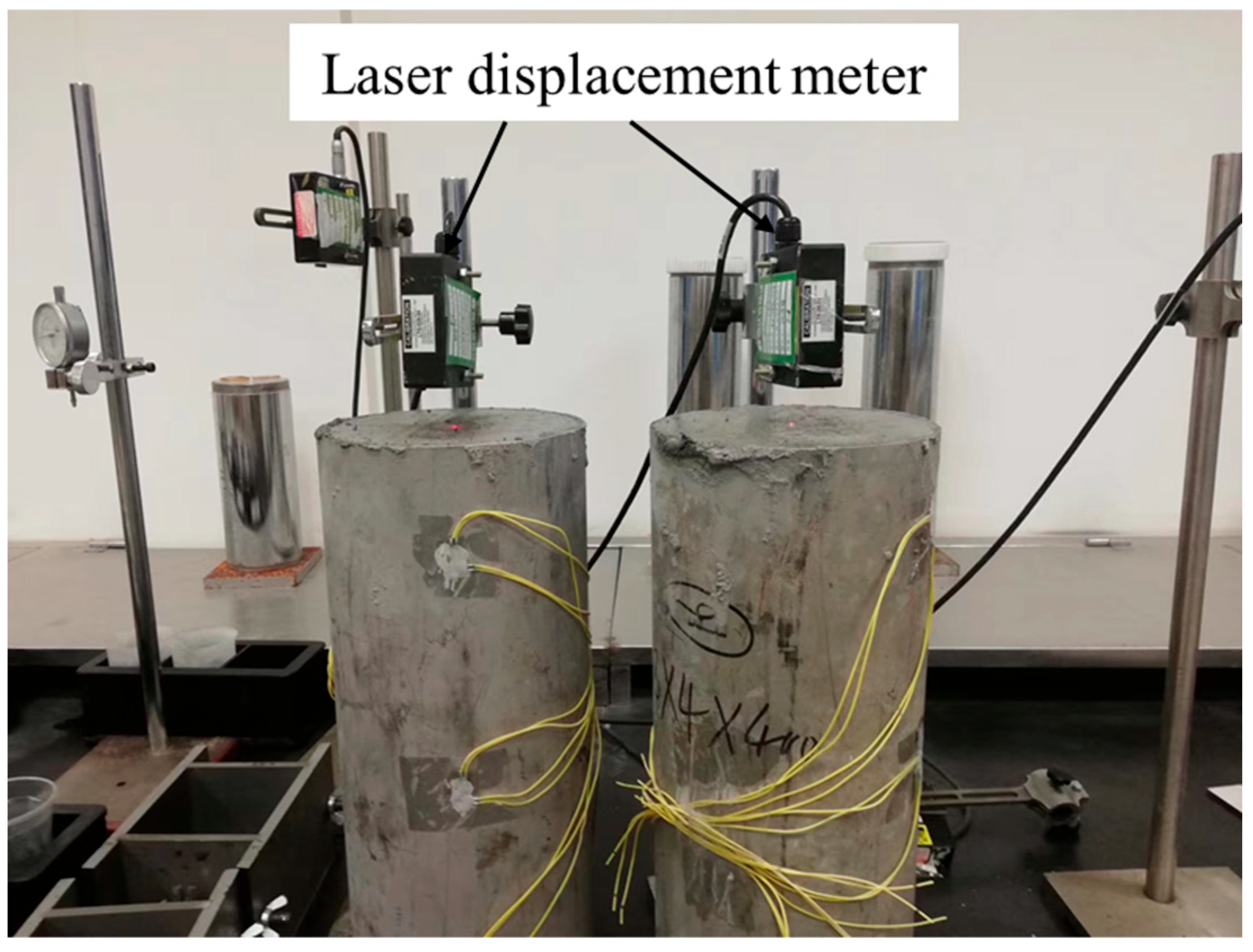
Two experiments were carried out to gauge the longitudinal expansion rate of concrete under steel pipe restraint after adding the expansion agent into the concrete. Firstly, a test to assess the longitudinal expansion rate was carried out, and the displacement of the vertical expansion was recorded, mainly by a laser displacement meter. This is shown in Figure 2.
In order to explore the working mechanism of micro-expansion concrete-filled steel pipes, axial compression experiments of nine samples were carried out. The experiment process was as follows:
(1)
Prior to the axial compression test, the MCFST members were placed in such a way that the steel tubes and the micro-expanded concrete were in the same straight line, so that the steel tubes and the micro-expanded concrete could share the load and avoid eccentric compression of the members. Similarly, the steel pipe members filled with micro-expanded concrete were leveled where they were placed.
(2)
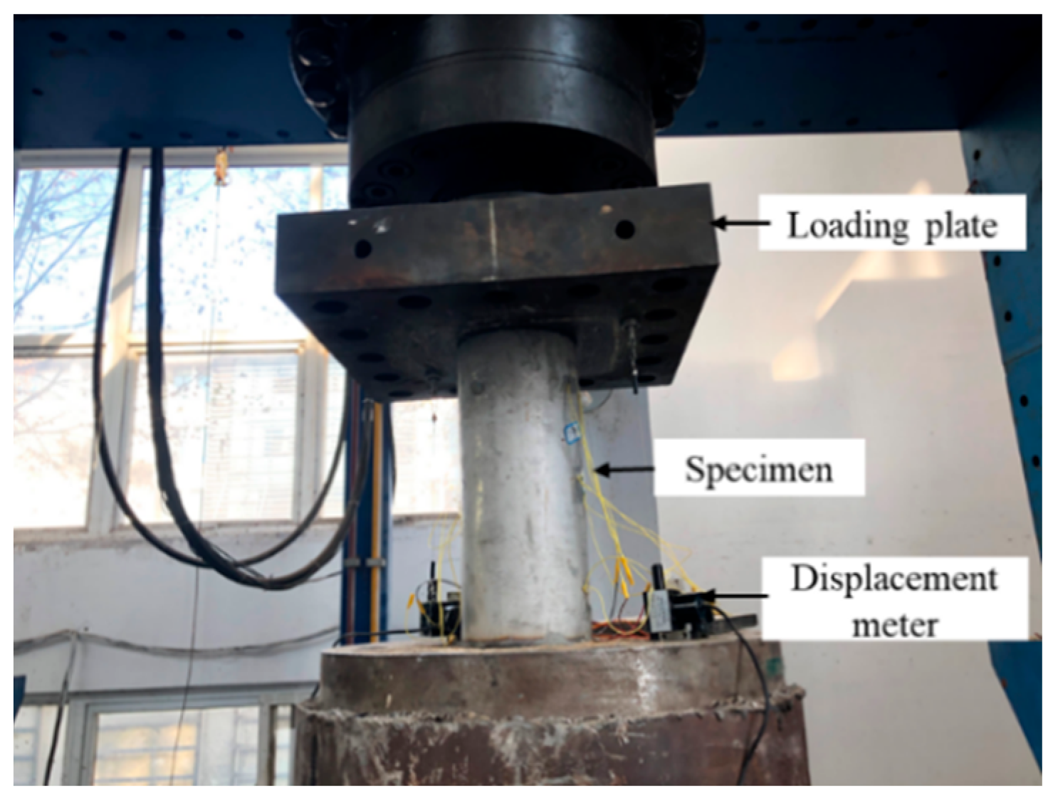
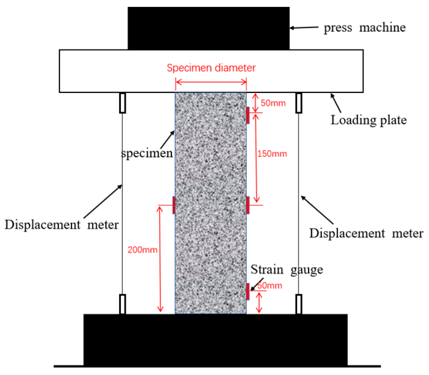
The center of the short micro-expansion CFST column was aligned with the loading center of the axial compression test apparatus to ensure that the member was subjected to axial compression rather than eccentric compression, and a displacement meter was placed between the test devices to measure the displacement, as shown in Figure 3 and Figure 4.
(3)
The steel pipe micro-expansion concrete member was placed on the testing machine, and the strain gauge was ground with a ten-color wire, and then connected to the static compound resistance strain gauge of Donghua Company for debugging. After debugging, the specimen was preloaded in the elastic range to ensure that the strain gauges worked properly. The strain gauge model was 120-5AA, which belonged to the terminal and did not require welding. The strain gauge above and below the specimen was mainly used to measure the changing trend of the end part of the specimen under load, while the strain gauge in the middle was mainly used to measure the changing trend of the middle part of the specimen under load. The upper and lower strain gauges were 50 mm away from the end, and the middle strain gauge divided the specimen into two equal parts. The preloading time was about 2 min. The preloading load should not exceed 30% of the theoretical calculated value of the load capacity of the specimen.
(4)
When the loading reached the yield point of the specimen, the displacement loading was adopted, and the experiment was finished when the displacement reached 100 mm.

3. Experiment Results

Through the axial compression test of the steel tube micro-expansion concrete short columns in this section, the load–displacement curve, destruction mode, and load–strain curve of the specimens under axial compression load were obtained. The failure mode and failure mechanism of the specimens are described. The load–displacement curve and load–strain curve of the samples were also analyzed.

3.1. Failure Mode and Mechanism Analysis

  • Longitudinal expansion experiment
The longitudinal expansion rate of concrete mixed with an expansion agent was obtained according to the method provided in the national code Technical Code for Application of Concrete Admixtures (GB501119-2013 [24]). For the test equipment, a laser displacement meter was used. Under the condition of lateral restraint, the longitudinal expansion rate of concrete in this study was calculated according to the following formula:
ε c = L c L 0 L × 100 %
where:
  • ε c —Longitudinal free expansion rate of concrete after curing;
  • L —Base length of concrete (400 mm);
  • L 0 —The initial length of concrete, 400 mm (the initial shrinkage of the concrete is not considered in this paper);
  • L c —Displacement meter reading of concrete after curing (mm).
In order to investigate the free expansion rate for different expansion agent contents, Figure 5 exhibits the free expansion rate–age curves. In the first phase, the expansion rate of micro-expansion concrete increases rapidly, and then the expansion results gradually reduce due to the shrinkage of micro-expansion concrete. When the concrete shrinkage guide is expanding, a descending section of the curve appears, and expansion and contraction are balanced. There are three distinct phases in the concrete after the admixture of expansion agents: the expand phase, shrink phase, and unchanged phase. This is due to the fact that before the unchanged phase, the expansion capacity produced by concrete expansion is greater than the shrink capacity, and the expansion capacity gradually diminishes during the expansion process. When the expansion capacity is smaller than the shrink capacity, the contraction appearance starts to emerge, and finally the equilibrium phase is reached.
2.
Axial compression experiment results
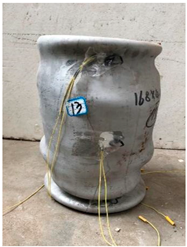
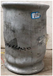
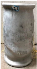
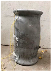
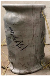
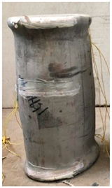
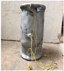
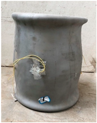
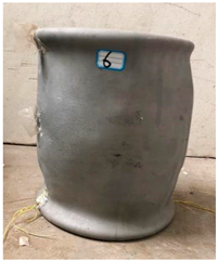
The failure modes of the specimens are shown in Table 3. It can be seen from Table 3 that all the specimens showed the failure mode of bulging in the middle and concave at both ends. The failure modes of micro-expansion concrete-filled steel tube short columns are essentially the same as those of ordinary CFST short columns. In the initial stage of loading, the short column of steel tube micro-expansion concrete is in an elastic state, the round steel tube and micro-expansion concrete bear external axial force, respectively, and the Poisson’s ratio of micro-expansion concrete is less than that of outer steel tube. Therefore, under the action of an external load, the steel pipe and the micro-expanded concrete are not subjected to mutual compression. At this stage, there is no mutual binding between the steel pipes and micro-expansion concrete. There is also no obvious deformation. With the continuous increase in the load, both steel pipes and concrete transition from the elastic phase to the yield phase, and the longitudinal strain becomes larger and larger. Micro-cracks begin to appear and develop in micro-expansion concrete. The Poisson’s ratio of micro-expansion concrete gradually goes over that of steel tubes. At this stage, steel pipe concrete elements have entered the plastic phase. After the steel tube completely yields and the concrete has been crushed, the carrying capacity of the member decreases rapidly. When the lateral deformation coefficient of the micro-expansion concrete is greater than that of the outer steel tube, circumferential stress is generated between the steel tube and the micro-expansion concrete, and the steel tube begins to experience radial forces.
According to the Von Mises yield criterion, when the circumferential stress of the steel tube increases gradually, the corresponding longitudinal stresses have decreased and the forces between the steel pipe and the micro-expanded concrete have been redistributed [20]. Micro-expansion concrete has a higher compressive strength due to the constraint of the steel pipe. The steel pipe changes from mainly bearing the axial load to mainly bearing the circumferential stress caused by micro-expansion deformation [20]. However, the yield of the steel pipe does not mean that the whole specimen has lost its carrying capacity. After the yield of the steel tube, the internal forces resulting from the interaction between the steel pipe and the micro-expanded concrete have been redistributed, which strengthens the deformation coordination ability between them. At the same time, the Poisson’s ratio of concrete in the plastic stage is much larger than that of the steel tube. After the concrete is crushed, the bearing capacity of the member may continue to rise due to the hooping effect of the steel pipe on it and the further joint work of the steel pipe and concrete. Therefore, the carrying capacity is further improved after the steel tube yields.

3.2. Load–Displacement Curve

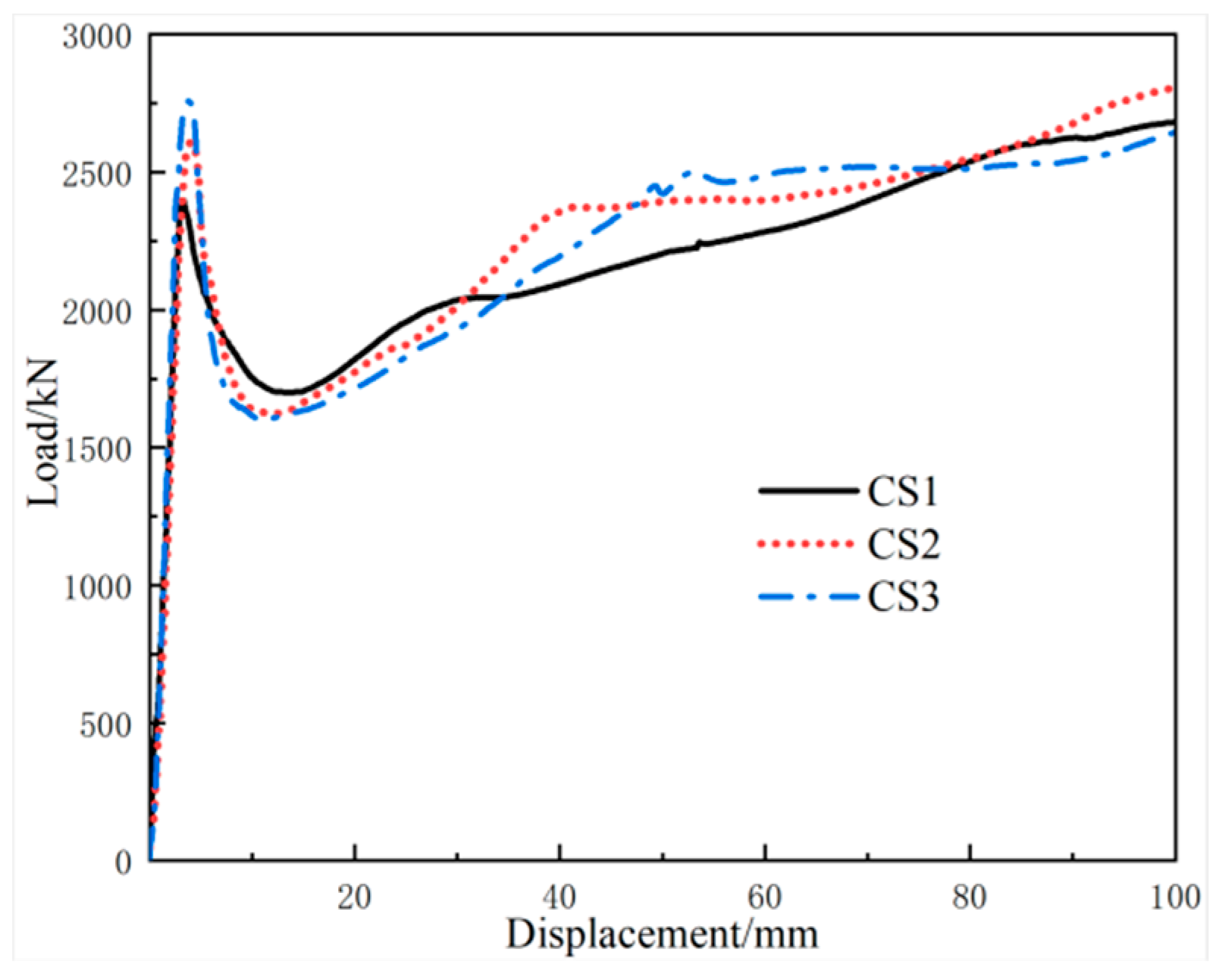
In order to study the change in displacement of all the specimens under axial compressive loading, the displacement of the specimen was obtained from two pre-placed displacement meters to obtain the load displacement curve. The load–displacement curve of the axial compression test of the micro-expansion concrete-filled steel tube short column is shown in Figure 6, Figure 7, Figure 8 and Figure 9. From Figure 6, it can be seen that at the initial stage of loading, specimens C1, C2, and C3 are in the elastic stage, and the load displacement curve increases linearly. With the continuous increase in load, the short column begins to enter the elastic-plastic stage, and the curve slope gradually slows down, indicating that the stiffness of the short column begins to change. At this time, the three-dimensional restraint effect of the micro-expansion concrete receiving the steel tube is more obvious. Under the condition of the steel tube restraint effect, the compressive strength of the micro-expansion concrete increases. Then, when the steel tube begins to buckle, the restraint effect of the steel tube on the micro-expansion concrete decreases, and the bearing capacity begins to decrease in varying degrees. However, due to the hoop effect of the steel tube, the specimen does not appear to show any obvious damage. After the bearing capacity decreases to a certain value, the load keeps increasing slowly and the displacement increases. It can be seen from the load–displacement curve in Figure 6 that the yield strength of the MCFST column is greater than that of ordinary CFST. The bearing capacity of the ordinary CFST column is 2399 kN, and the bearing capacities of the MCFST columns with C2 and C3 are 2612 kN and 2758 kN, respectively. The yield loading of the MCFST pier of C2 and C3 is 8.9% and 14.9% greater than the ordinary CFST column. Obviously, the micro-expansion concrete can notably increase the bearing capacity of the MCFST column. This is mainly due to the fact that expansion agents in concrete play an important role in compensating for the shrinkage defects of ordinary concrete. After curing, the micro-expansion concrete will produce self-stress under the double influence of concrete micro-expansion and steel pipe restraint.
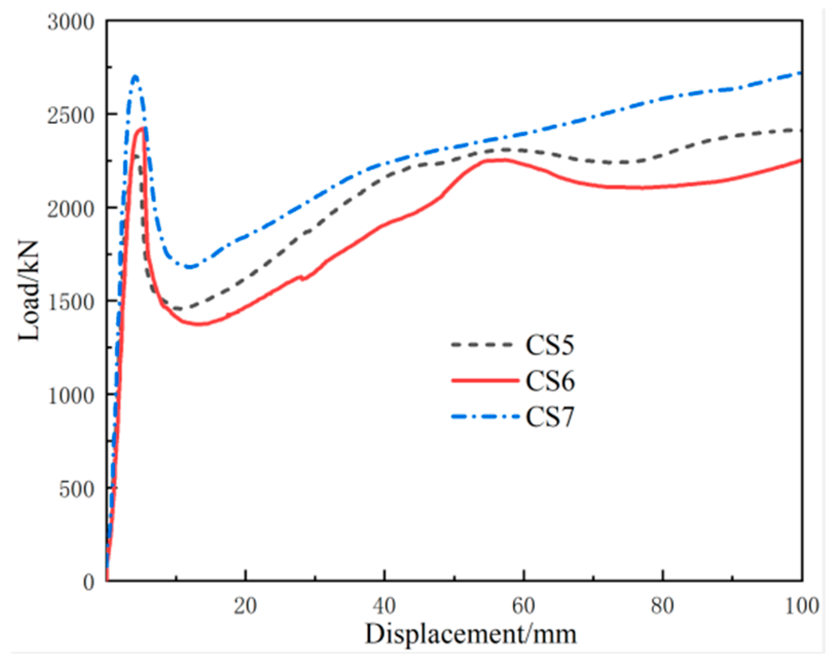
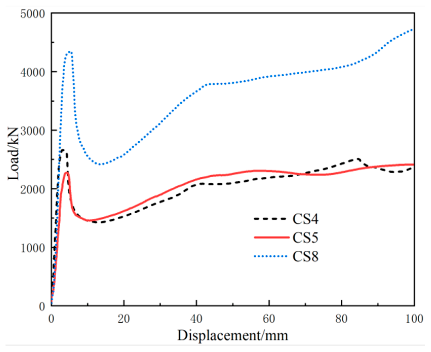
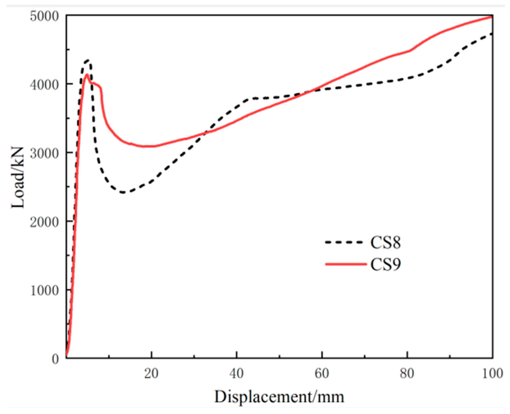
As can be seen from the load-displacement curves of different thicknesses in Figure 7, the wall thicknesses of CS5, CS6, and CS7 are 3 mm, 4 mm, and 5 mm, respectively, and the corresponding bearing capacities are 2275 kN, 2422 kN, and 2700 kN, respectively. When the wall thickness increases from 3 mm to 4 mm, the bearing capacity increases by 6.5%, and when the wall thickness increases from 3 mm to 5 mm, the bearing capacity increases by 18.7%. The results show that the bearing capacity of steel tube micro-expansion concrete short columns will increase with the increase in the steel tube wall thickness. Because the load–displacement curve shows the elastic modulus of the specimen in the elastic stage, so we can see the bearing capacity at yield and the ductility after yield. Therefore, it can be seen from Figure 7 that the stiffness of different thicknesses in the elastic stage is essentially the same, but when the elastic stage transitions to the elastic-plastic stage, the stiffness with high wall thickness is significantly greater than that with small wall thickness. The yield bearing capacity is significantly improved, and the level of ductility is good. As can be seen from the load–displacement curves of different diameters in Figure 8, the outer diameters of the steel tubes of CS5, CS4, and CS8 are 159 mm, 168 mm, and 219 mm, respectively, and the corresponding bearing capacities are 2275 kN, 2661 kN, and 4345 kN, respectively. When the outer diameter of the steel tube increases from 159 mm to 168 mm, the bearing capacity increases by 16.9%, and when the outer diameter of the steel tube increases from 159 mm to 219 mm, the bearing capacity increases by 90.9%. The results show that the bearing capacity of steel tube micro-expansion concrete short columns will increase with the increase in the outer diameter of the steel tube. It can be seen from the load–displacement curves of different end constraints in Figure 9 that the load–displacement curves of CS9 and CS8 are the load–displacement curves of end unconstrained and end constrained, respectively, and the corresponding bearing capacities are 4134 kN and 4345 kN, respectively. When the end of the steel tube is unconstrained relative to the end constraint, the bearing capacity is increased by 5.1%, indicating that the end constraint will reduce the bearing capacity of the test specimen.

3.3. Load–Strain Curve

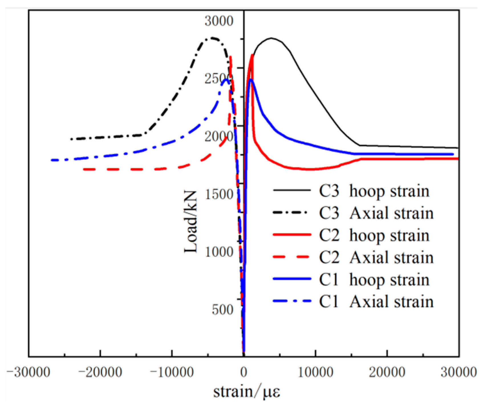
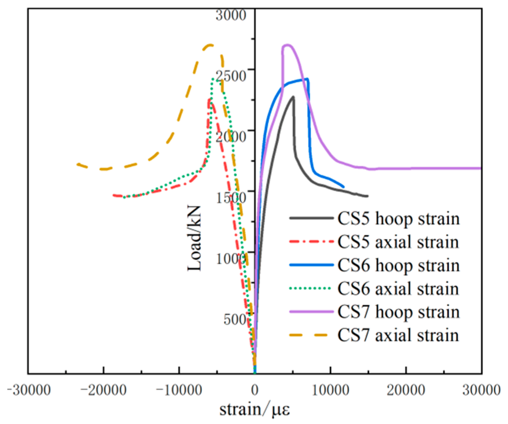
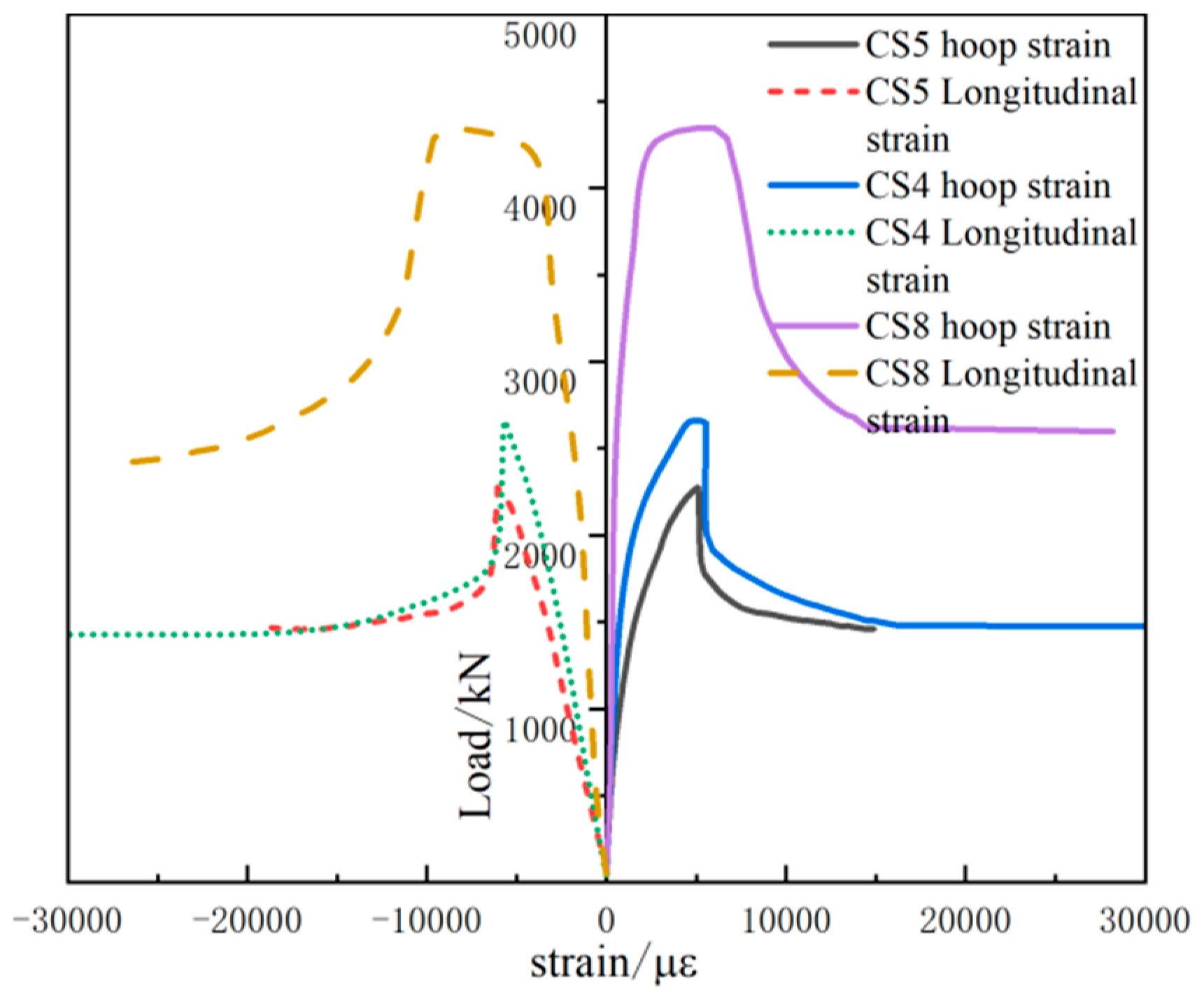
In order to study the deformation of MCFST and CFST under axial compressive loading, the longitudinal strain and circumferential strain of the middle section are used to represent the longitudinal strain and circumferential strain of the whole specimen. According to the test results, the load-strain (N-ε) of all the test specimens is obtained. The load-strain of all the specimens is shown in Figure 10, Figure 11, Figure 12 and Figure 13. It can be seen from Figure 10 that the strain of the micro-expansion concrete-filled steel tube under the same load is greater than that of steel tube ordinary concrete from the initial stage of loading to yield. This is mainly because the stiffness of the whole specimen is reduced after adding the expansion agent into the concrete. After yielding, for the ordinary concrete-filled steel tube, the ultimate load is reached soon after yielding and enters the descending section quickly. For the micro-expansion concrete-filled steel tube, after yielding, the specimen reaches the ultimate load after experiencing considerable deformation, and then enters the descending section. This is mainly due to the self-stress generated when the steel tube constrains the micro-expansion concrete, which strengthens the cooperative working ability of the steel tube and the micro-expansion concrete after the specimen is subject to buckling. When the ultimate load is reached, the tensile zone and compression zone reach the peak at the same time. This shows that the cooperation between the steel tube and concrete is good. Throughout the whole loading process, under the same load, the strain in the compression zone is greater than that in the tension zone. This means that the specimen will reach the yield stage first in the compression zone. From Figure 10, it can be seen that the initial stiffness of the specimen is reduced for specimens with an expansion agent, but the stiffness will essentially remain unchanged with the increase in the content of the expansion agent. With the increase in the content of the micro-expansion agent, the bearing capacity of the specimen gradually decreases. The ductility of the specimens is also enhanced. As can be seen from Figure 11 and Figure 12, with the increase in the steel tube wall thickness and the steel tube diameters, the bearing capacity of the test piece gradually increases. As shown in Figure 13, the bearing capacity with end restraint is lower than that without end restraint. This is because the same expanding agent may have different mechanisms of action in different constraint states. The self-stress produced by the end restraint specimen is large, but the bearing capacity is reduced. Therefore, the content of the concrete expansion agent will have the most appropriate proportion.
In the past decades, China has made great breakthroughs and progress in the research and application of concrete-filled steel tube structures, and the research on the theoretical calculation formula of CFST structures is also relatively mature. However, there is no specific code for calculating the axial compressive capacity of concrete-filled steel tube columns. Therefore, this study modifies the practical calculation method of the axial pressure of CFST columns based on the existing experiment results, while referring to the calculation formula of the carrying capacity of ordinary concrete-filled steel tube columns in the existing specifications. The aim was to predict the axial bearing capacity of short columns of MCFST, there are three main methods for calculating the axial compressive carrying capacity of ordinary CFST: the unified theory; the superposition theory; and the limit equilibrium theory. Zhong [25] put forward the unified theory and unified design method. The main conclusion of the unified theory of concrete-filled steel tubes is that the two materials of steel tube and concrete are combined to form a composite material by using the deformation coordination condition, and the mechanical properties of concrete-filled steel tube structures change with the change in the geometric parameters and section form. However, the calculation is unified. The unified formula is used to calculate the bearing capacity of concrete-filled steel tube structures under axial compression load:
N u = A s c × f s c
f s c = 1.212 + B θ + C θ 2 f c k θ = α f / f c
where:
  • N 0 —Design value of the axial compression bearing capacity of a concrete-filled steel tube;
  • A s c —The cross-sectional area of the concrete-filled steel tube composite structure is equal to the sum of the steel tube area and the concrete area;
  • f s c —Compressive strength value of CFST;
  • θ —Confinement coefficient of specimen;
  • α —The steel content of the specimen is the ratio of the cross-sectional area of the steel tube to the cross-sectional area of the concrete;
  • f , f c —The design values of the compressive strength of steel and concrete, respectively;
  • B,C—The influence coefficient of the confinement coefficient (depending on different section shapes); value according to Table 4.
Han [26] proposed the theory of the superposition of the bearing capacity of both steel pipes and concrete. The superposition theory is mainly composed of the bearing capacity of steel tubes and concrete when they are stressed separately. As with the carrying capacity of CFST composite structures, in the existing specifications, the round steel tube partially considers the influence of the three-dimensional restraint of concrete by the steel tube, and the compressive strength of core concrete will be improved. There are also other codes that do not take into account the three-dimensional keep within bounds effect of steel tubes on concrete, while the three-dimensional restraining effect of steel pipes on concrete is seldom considered for square steel pipe concrete. The following bearing capacity formula is used for cases where the restraining effect is not considered:
N u = η s f y A s + η c f c k A c
where:
  • η s —Variation coefficient of steel tube bearing capacity;
  • η c —Variation coefficient of bearing capacity of concrete.
If the three-dimensional restraint effect of the steel tube on concrete is not considered, it is taken as η s = 1 , η c = 1 . If the three-dimensional action of the steel tube on concrete is considered, the bearing capacity coefficient of the steel tube remains unchanged as η s = 1 , and the bearing capacity coefficient of concrete is expressed as follows:
η c = 1 + ( 4 3 β 2 1 ) α f y / f c k
where: β = 0.25 + 0.32 α ; α is the steel content of the specimen; and the value is the ratio of the cross-sectional area of the steel tube to the concrete area.
Cai [27] put forward the limit equilibrium theory of concrete-filled steel tube composite structures. The main conclusion of this theory is that the bearing capacity of concrete-filled steel tube structures is less affected by the deformation mode and loading mode. The bearing capacity is calculated by using the equilibrium condition in the limit state, and the bearing capacity obtained by experimental research and theoretical calculation is based on the hoop coefficient θ. There are different calculation methods:
N u = A c f c ( 1 + 2 θ ) ;     θ 1.235 N u = A c f c ( 1 + θ + 1.1 θ ) ;     θ 1.235
where:
  • θ = A s × f y A c × f c —Formula for calculating the hoop coefficient;
  • f y —Steel tube yield strength;
  • f c —Compressive strength of concrete.
Eurocode EC4-2004 [28]: The calculation formula of the axial compression bearing capacity of concrete-filled steel tube with different sections is proposed. When the concrete-filled steel tube column meets both the slenderness ratio λ ¯ 0.5 and eccentricity e / d 0 . 1 , the three-dimensional restraint effect of concrete should be considered. The calculation formula of the axial compression bearing capacity is as follows:
N N u
N u = f y γ s A s + f c γ c A c
where:
  • N—Axial compression bearing capacity design value;
  • Nu—Axial load bearing capacity limit.
When considering the hoop effect of the steel tube on the concrete, the calculation formula of the axial compressive bearing capacity of the member is:
N u = η s f y γ s A s + ( 1 + η c × t D f y f c ) f c γ c × A c
η c = 4.9 18.5 λ ¯ + 17 λ ¯ 2 0
η s = 0.25 ( 3 + 2 λ ¯ ) 1
where:
  • A s , A c —The steel tube section area and concrete section area;
  • f y , f c —The yield strength of the steel pipe and compressive strength of the concrete;
  • γ s , γ c —The partial coefficient of steel (generally 1.0), partial coefficient of concrete (generally 1.5);
  • η s , η c —Coefficient.
When the slenderness ratio of the concrete-filled steel tube column is not considered, the calculation formula of the axial compression bearing capacity can be simplified as follows:
N u = 0.75 f y γ s A s + ( 1 + 4.9 × t D f y f c ) × f c A c
There have been many studies on the bearing capacity formula of concrete-filled steel tubes, as shown in Table 5, which presents the typical codes for the calculation of the axial compressive ultimate bearing capacity of CFST at home and abroad.

3.4. Empirical Formula Based on Experimental Results

Under the action of axial compression load, the bearing capacity of MCFST columns is higher than that of ordinary concrete-filled steel tubes. The main reason for this is that the three-dimensional restraint effect of steel tubes on micro-expansion concrete is strengthened due to the expansion of the micro-expansion concrete. Due to the use of micro-expansion concrete, there will be large errors in the existing calculation formula of the axial compression bearing capacity of concrete-filled steel tube columns.
The calculation and test results of different standard formulas are shown in Table 6. It can be seen that the error between the calculation formula of the bearing capacity of concrete-filled steel tube columns in the European Code (Eurocode 4) and the test results in this study is the smallest, with an error of 9.8%. The increase in the axial compression bearing capacity of steel tube micro-expansion concrete columns is due to the increase in the passive confining pressure of steel tubes on concrete due to the expansion of concrete. Therefore, referring to the bearing capacity calculation formula of Eurocode 4, this paper introduces the strength improvement coefficient considering the three-dimensional restraint of steel tubes to concrete, and puts forward an intuitive and convenient axial compression bearing capacity calculation formula of steel tube micro-expansion concrete column for engineering applications.
N u = 0.75 f y γ s A s + ( 1 + 4.9 × t D f y f c ) × β f c A c
These include the improvement coefficient β of strength under the constraint of the steel tube after adding the expansion agent into the concrete; the meaning of the other symbols is consistent with the previous text. Substitute the test data into the formula Nu, and the corresponding coefficient of MCFST is shown in Table 7.
The steel pipe diameter and steel content of each specimen are different, but the coefficient is very close. The coefficient β = 1.2 can be obtained by linear regression of the coefficient, that is, the practical bearing capacity calculation formula based on the test results is as follows:
N u = 0.75 f y γ s A s + ( 1 + 4.9 × t D f y f c ) × 1.2 f c A c

4. Conclusions

In order to explore the mechanical properties of micro-expansion concrete-filled steel tube columns under axial compression, axial compression tests were carried out on 9 specimens. The experimental results show that:
  • The experiment results of the longitudinal volume expansion rate show that the displacement of concrete expansion increases with the increase in the expansion agent content.
  • The damage pattern of all the specimens was bulging and curved in the center and concave at the ends. With the increase in the expansion agent content, the bearing capacity of the specimen increased. The yield strengths of micro-expansion concrete-filled steel tube columns added with 8% and 12% expansion agent were 8.9% and 14.9% higher than the concrete-filled steel tube short column. This indicates that the addition of an expansion agent to concrete has a positive effect on its axial compressive load-bearing capacity.
  • When the expansion agent exceeded a certain size, the bearing capacity decreased. This indicates that there is an optimum content of expansion agent incorporated into concrete. The next step is to prepare an experimental study to ascertain the specific ratio of the optimum content.
  • A practical bearing capacity calculation formula based on the test results is proposed, which provides a reference for practical engineering applications. The next step is to carry out the bearing capacity test on more specimens to optimize the formula, so that the formula can be used in a wider range of applications.
  • While this study confirmed the reliability of micro-expansion concrete in filling steel tube members through experimental methods, the testing conditions limited the ability to conduct experiments on full-scale specimens with high slenderness ratios. Future research efforts could focus on establishing simulation methods for micro-expansion concrete and utilizing validated numerical simulation techniques to investigate the response of full-scale specimens. This approach would enhance the understanding of micro-expansion concrete performance in practical applications and improve the reliability and applicability of the research findings.

Author Contributions

X.L.: methodology, original draft preparation, project administration, software; J.H.: investigation, review and editing; Y.Z.: project administration, writing—review and editing, supervision, methodology, data curation, validation. All authors have read and agreed to the published version of the manuscript.

Funding

This research was funded by the Guangzhou Construction Group Technology Plan Project (Grant no. [2024]-KJ012).

Data Availability Statement

The raw data supporting the conclusions of this article will be made available by the authors on request.

Conflicts of Interest

Author Xin Liu was employed by the company Guangzhou Second Municipal Engineering Co., Ltd. and Guangzhou Construction Group Co., Ltd. and Jisheng Hu was employed by the company Guangzhou Second Municipal Engineering Co., Ltd. The remaining authors declare that the research was conducted in the absence of any commercial or financial relationships that could be construed as a potential conflict of interest.

References

  1. Güneyisi, E.M.; Nour, A.I. Axial compression capacity of circular CFST columns transversely strengthened by FRP. Eng. Struct. 2019, 191, 417–431. [Google Scholar] [CrossRef]
  2. Yan, J.-B.; Dong, X.; Wang, T. Axial compressive behaviours of square CFST stub columns at low temperatures. J. Constr. Steel Res. 2020, 164, 105812. [Google Scholar] [CrossRef]
  3. He, L.; Zhao, Y.; Lin, S. Experimental study on axially compressed circular CFST columns with improved confinement effect. J. Constr. Steel Res. 2018, 140, 74–81. [Google Scholar] [CrossRef]
  4. Dong, H.; Li, Y.; Cao, W.; Qiao, Q.; Li, R. Uniaxial compression performance of rectangular CFST columns with different internal construction characteristics. Eng. Struct. 2018, 176, 763–775. [Google Scholar] [CrossRef]
  5. Huang, Y.-H.; Liu, A.-R.; Fu, J.-Y.; Pi, Y.-L. Experimental investigation of the flexural behavior of CFST trusses with interfacial imperfection. J. Constr. Steel Res. 2017, 137, 52–65. [Google Scholar] [CrossRef]
  6. Ouyang, Y.; Kwan, A. Finite element analysis of square concrete-filled steel tube (CFST) columns under axial compressive load. Eng. Struct. 2018, 156, 443–459. [Google Scholar] [CrossRef]
  7. Knowles, R.B.; Park, R. Strength of concrete filled steel tubular columns. J. Struct. Div. ASCE 1969, 95, 2565–2587. [Google Scholar] [CrossRef]
  8. Knowles, R.B.; Park, R. Axial load design for concrete filled steel tubes. J. Struct. Div. ASCE 1970, 96, 2125–2153. [Google Scholar] [CrossRef]
  9. Tomii, M. Experimental studies on concrete filled steel tubular stub columns under concentric loading. In Proceedings of the International Colloquium on Stability of Structures Under Static and Dynamic Loads, SSRC/ASCE, Washington, DC, USA, 17–19 May 1977. [Google Scholar]
  10. Luksha, L.K.; Nesterovich, A.P. Strength testing of large-diameter concrete filled steel tubular members. In Proceedings of the Third International Conference on Steel-Concrete Composite Structures, Fukuoka, Japan, 26–29 September 1991; Wakabayashi, M., Ed.; Association for International Cooperation and Research in Steel-Concrete Composite Structures: Fukuoka, Japan, 1991; pp. 67–72. [Google Scholar]
  11. Srinivasan, C.N.; Schneider, S.P. Axially loaded concrete-filled steel tubes. J. Struct. Eng. 1988, 125, 1202–1206. [Google Scholar] [CrossRef]
  12. Giakoumelis, G.; Lam, D. Axial capacity of circular concrete-filled tube columns. J. Constr. Steel Res. 2004, 60, 1049–1068. [Google Scholar] [CrossRef]
  13. Sakino, K.; Nakahara, H.; Morino, S.; Nishiyama, I. Behavior of centrally loaded concrete-filled steel-tube short columns. J. Struct. Eng. 2004, 130, 180–188. [Google Scholar] [CrossRef]
  14. Ellobody, E.; Young, B.; Lam, D. Behaviour of normal and high strength concrete-filled compact steel tube circular stub columns. J. Constr. Steel Res. 2006, 62, 706–715. [Google Scholar] [CrossRef]
  15. Gupta, P.; Sarda, S.; Kumar, M. Experimental and computational study of concrete filled steel tubular columns under axial loads. J. Constr. Steel Res. 2007, 63, 182–193. [Google Scholar] [CrossRef]
  16. Liang, Q.Q.; Fragomeni, S. Nonlinear analysis of circular concrete-filled steel tubular short columns under axial loading. J. Constr. Steel Res. 2009, 65, 2186–2196. [Google Scholar] [CrossRef]
  17. Abed, F.; AlHamaydeh, M.; Abdalla, S. Experimental and numerical investigations of the compressive behavior of concrete filled steel tubes (CFSTs). J. Constr. Steel Res. 2013, 80, 429–439. [Google Scholar] [CrossRef]
  18. Huang, C.K.; Xu, L.; Liu, Y. Experimental study on axial compressive properties of self-compacting and self-stressing concrete filled steel tube short columns. J. Dalian Univ. Technol. 2006, 77–82. (In Chinese) [Google Scholar]
  19. Lu, Y.Y.; Yan, B.; Li, N.; Li, S. Compressive Behavior of Steel Tube Columns Filled with Steel Fiber Reinforced Self-stressing and Self-compacting Concrete. J. Civ. Eng. Manag. 2017, 34, 1–4. [Google Scholar]
  20. Xu, L.H.; Wu, M.; Zhou, P.H. Experimental study on axial compression bearing capacity of self-stressing and self-compacting high strength concrete filled steel tubular short columns. Eng. Mech. 2017, 93–100. (In Chinese) [Google Scholar]
  21. Armaghani, D.J.; Safari, V.; Fahimifar, A.; Amin, M.F.M.; Monjezi, M.; Mohammadi, M.A. Uniaxial compressive strength prediction through a new technique based on gene expression programming. Neural Comput. Appl. 2018, 30, 3523–3532. [Google Scholar] [CrossRef]
  22. Sarir, P.; Chen, J.; Asteris, P.G.; Armaghani, D.J.; Tahir, M.M. Developing GEP tree-based, neuro-swarm, and whale optimization models for evaluation of bearing capacity of concrete-filled steel tube columns. Eng. Comput. 2021, 37, 1–19. [Google Scholar] [CrossRef]
  23. Sarir, P.; Shen, S.-L.; Wang, Z.-F.; Chen, J.; Horpibulsuk, S.; Pham, B.T. Optimum model for bearing capacity of concrete-steel columns with AI technology via incorporating the algorithms of IWO and ABC. Eng. Comput. 2021, 37, 797–807. [Google Scholar] [CrossRef]
  24. GB 50119-2013; Code for Utility Technical of Concrete Admixture. China Standard Press: Beijing, China, 2013.
  25. Zhong, S.T. Unified Theory of Concrete Filled Steel Tubular: Research and Application; Tsinghua University Press: Beijing, China, 2006. [Google Scholar]
  26. Han, L.H. Concrete Filled Steel Tube Structure-Theory and Practice; Science Press: Beijing, China, 1990. [Google Scholar]
  27. Cai, S.H. Modern Concrete Filled Steel Tube Structure; People’s Communications Press: Beijing, China, 2007. [Google Scholar]
  28. EN 1994-1-1; Eurocode4: Design of Composite Steel and Concrete Structures—Part 1-1: General Rules and Rules for Buildings. European Committee for Standardization: Brussels, Belgium, 2004.
  29. ACI-318R; Building Code Requirements for Structural Concrete and Commentary. American Concrete Institute: Farmington Hills, MI, USA, 2005.
  30. AS3600; Australian Standards. Concrete Structures. Standards Association of Australia: Sydney, Australia, 2001.
  31. AIJ. Standards for Structural Calculation of Steel Reinforced Concrete Structures, 5th ed.; Architectural Institute of Japan: Tokyo, Japan, 2001. (In Japanese) [Google Scholar]
  32. CECS 28:2012; Technical Specification for Concrete Filled Steel Tube. China Planning Press: Beijing, China, 2012.
  33. GB 50936-2014; Code for Design of Concrete Filled Steel Tube Structures. China Construction Industry Press: Beijing, China, 2014.
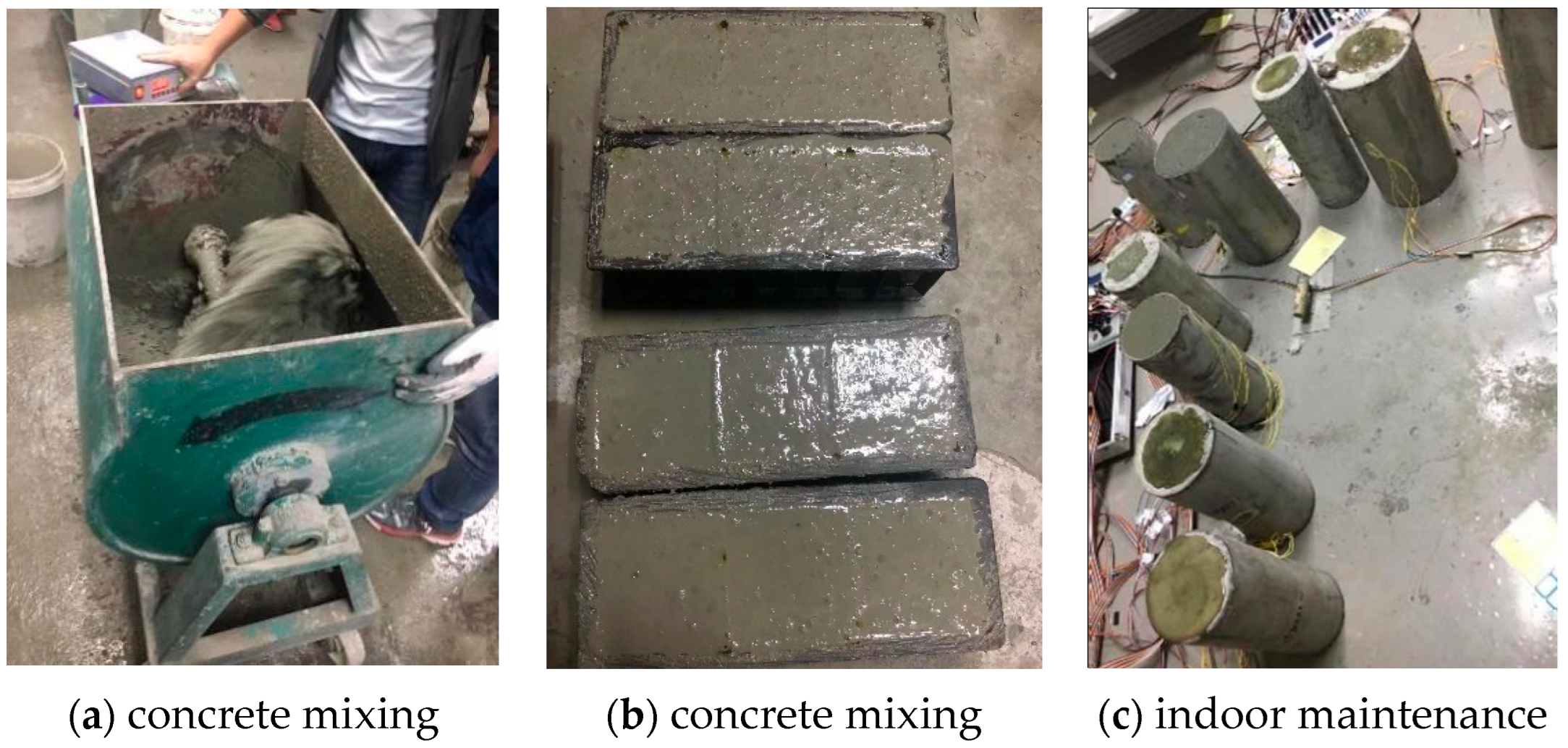
Figure 1. The production process of all the specimens.
Designs 08 00090 g001
Figure 2. Volume expansion experiment equipment.
Designs 08 00090 g002
Figure 3. Loading equipment.
Designs 08 00090 g003
Figure 4. Schematic diagram of loading equipment.
Designs 08 00090 g004
Figure 5. Free expansion rate-age curve.
Designs 08 00090 g005
Figure 6. Load–displacement curves with different expansion rates.
Designs 08 00090 g006
Figure 7. Load–displacement curves of different thicknesses.
Designs 08 00090 g007
Figure 8. Load–displacement curves with different diameters.
Designs 08 00090 g008
Figure 9. Load–displacement curves with and without end constraints.
Designs 08 00090 g009
Figure 10. Load strain curves with different expansion rates.
Designs 08 00090 g010
Figure 11. Load strain curves of different thicknesses.
Designs 08 00090 g011
Figure 12. Load strain curves with different diameters.
Designs 08 00090 g012
Figure 13. End constrained and unconstrained load strain curves.
Designs 08 00090 g013
Table 1. Parameters of the specimens.
IDD (mm)Length (mm)t (mm)fc (MPa)V Remarks
CS11684004800
CS21684004808%
CS316840048012%
CS416840038012%
CS515940038012%
CS615940048012%
CS715940058012%
CS821940038012%
CS921940038012%end restraint
Table 2. Mix design of micro-expansion concrete.
IDCement (kg)Ganister Sand (kg)Slag (kg)Zeeospheres (kg)Expansion Agent (kg)Sand (kg)Big Cobble (kg)Small Cobble (kg)Water (kg)Water-Reducing Admixture (kg)fc (MPa)
M016.50.891.081.91/22.723.9310.256.190.1283.6
M812.60.750.921.621.3819.320.308.704.030.0785.2
M1211.90.750.921.622.0819.320.368.704.030.0786.2
Table 3. Failure mode of all the specimens.
SpecimensFinal Failure ModeDescription of Failure Mode
CS1Designs 08 00090 i001(1) No expansion agent
(2) The yield bearing capacity is 2399 kN
(3) The specimen shows the failure mode of bulging in the middle and concave at both ends
(4) The displacement of the specimen is loaded to 130 mm, which is more serious than other specimens.
CS2Designs 08 00090 i002(1) 8% expansion agent
(2) The yield bearing capacity is 2612 kN
(3) The specimen shows the failure mode of bulging in the middle and concave at both ends
(4) The lower concave deformation is larger than the upper one.
CS3Designs 08 00090 i003(1) 12% expansion agent
(2) The yield bearing capacity is 2758 kN
(3) The specimen shows the failure mode of bulging in the middle and concave at both ends
(4) Obvious shear slip lines.
CS4Designs 08 00090 i004(1) 12% expansion agent
(2) The yield bearing capacity is 2661 kN
(3) The specimen shows the failure mode of bulging in the middle and concave at both ends
(4) Significant shear slip lines.
CS5Designs 08 00090 i005(1) 12% expansion agent
(2) The yield bearing capacity is 2275 kN
(3) The specimen shows the failure mode of bulging in the middle and concave at both ends
(4) No significant shear slip lines.
CS6Designs 08 00090 i006(1) 12% expansion agent
(2) The yield bearing capacity is 2422 kN
(3) The specimen shows the failure mode of bulging in the middle and concave at both ends
(4) No significant shear slip lines.
CS7Designs 08 00090 i007(1) 12% expansion agent
(2) The yield bearing capacity is 2700 kN
(3) The specimen showed the failure mode of bulging in the middle and concave at both ends
(4) No significant shear slip lines.
CS8Designs 08 00090 i008(1) 12% expansion agent
(2) The yield bearing capacity is 4345 kN
(3) The specimen showed the failure mode of bulging in the middle and concave at both ends.
CS9Designs 08 00090 i009(1) 12% expansion agent
(2) The yield bearing capacity is 4134 kN
(3) The specimen showed the failure mode of bulging in the middle and concave at both ends.
Table 4. The influence coefficient of B and C.
Section ShapesBC
solidcircle and dodecagon 0.176 f / 213 + 0.974 0.104 f c / 14.4 + 0.031
regular octagon 0.140 f / 213 + 0.778 0.070 f c / 14.4 + 0.026
square 0.131 f / 213 + 0.723 0.070 f c / 14.4 + 0.026
hollowcircle and dodecagon 0.106 f / 213 + 0.584 0.037 f c / 14.4 + 0.011
regular octagon 0.056 f / 213 + 0.311 0.011 f c / 14.4 + 0.004
square 0.039 f / 213 + 0.217 0.006 f c / 14.4 + 0.002
Table 5. Typical codes for the calculation of the axial compressive ultimate bearing capacity of CFST columns at home and abroad.
Design CodeCalculation FormulaRemarks
ACI [29]/AS [30] N A C I / A S = 0.85 f c A c + f y A s
AIJ [31] N A I J = f c A c + ( 1 + η ) f y A s η = 0 for square steel tube; η = 0.27 for circular steel tube
Eurocode 4 [28] N u = 0.75 f y γ s A s + ( 1 + 4.9 × t D f y f c ) × f c A c Simplified formula without regard to the slenderness ratio
CECS28:2012 [32] 0.5 < θ [ θ ] , N C E C s = 0.9 A c f c k ( 1 + α 0 θ )
2.5 > θ > [ θ ] , N C E C S = 0.9 A c f c k ( 1 + θ + θ )
α 0 is coefficient; [ θ ] is limit value of hoop coefficient
GB50936 [33] N G B = A s c f s c f s c = 1.212 + B θ + C θ 2 f c k
A s c = A s + A c ; B, C as shown Table 4
Note: t is the wall thickness of the concrete-filled steel tube, D is the diameter of the concrete-filled steel tube, fy is the yield strength of the steel tube, fcd is the compressive strength of the concrete prism, γs, γc is the coefficient of steel (generally 1.0) and concrete (generally 1.5), respectively, and = fy As/fc Ac is the hoop coefficient of the MCFST.
Table 6. Calculation results of different specifications of specimen CS2.
Design CodeCalculation FormulaError Rate
ACI [29]/AS [30]1935.9 kN25.9%
AIJ [31]2322.9 kN11.1%
Eurocode 4 [28]2656 kN9.8%
CECS28:2012 [32]θ does not fit the formulaInapplicable
GB50936 [33]1646.2 kN36.9%
Table 7. The coefficient β of all the specimens.
SpecimenCoefficient β
CS21.20
CS31.28
CS41.28
CS51.48
CS61.24
CS71.32
CS81.27
Disclaimer/Publisher’s Note: The statements, opinions and data contained in all publications are solely those of the individual author(s) and contributor(s) and not of MDPI and/or the editor(s). MDPI and/or the editor(s) disclaim responsibility for any injury to people or property resulting from any ideas, methods, instructions or products referred to in the content.