Abstract
In this study, we propose a new toothed gear for mechanical transmissions built from a satellite wheel with two toothed conical crowns, one of which conjugates with a fixed central conical wheel mounted in the transmission housing and the other with a movable conical wheel installed on the flange of the driven shaft. The satellite wheel is mounted on the inclined portion of the crankshaft and performs spherospatial motion around a fixed point. When the crankshaft rotates, the teeth of the wheels engage with spherospatial interaction in two lateral gearings of the satellite wheel, yielding kinematic ratios dependent on the correlation of the number of teeth. The teeth of the satellite wheel are used with circular arc profiles, and the teeth of the central wheel have flank profiles with variable curvatures increasing continuously from the root to the tip, so that, in meshing, the teeth form multipair contacts with convex–concave geometry with a small difference in flank curvatures. The flank profile geometry and pairs of teeth simultaneously engage depending on the configurational parameters of the gearing and can use up to 100% of pairs of simultaneously conjugated teeth.
1. Introduction
The guiding question of this paper is “how to combine in a single mechanical transmission as extended a kinematic means as possible, with as high a load-bearing capacity and as small an energy loss as possible?”.
The modern requirements for mechanical gears consist, in particular, of increasing the reliability, efficiency, and bearing capacity and reducing the mass and the dimensions of transmissions. Satisfying the ever-increasing demands via partially modernizing classic transmissions is becoming increasingly difficult. This problem can be efficiently solved using two methods simultaneously applied, namely, by developing new types of mechanical transmissions based on new principles of transformation and transmission of movement and load by developing gearings with multipair tooth contact.
In the great diversity of mechanical transmissions, planetary transmissions with multipair gears occupy a special place. They have a series of advantages, namely, a high bearing capacity, coaxiality, compactness, reduced mass, high kinematic precision, the possibility of obtaining great transmission ratios, silent operation, etc. Planetary transmissions with multiple-pair gears have become widespread in different fields of machine building in recent decades and have witnessed continuously growing modernization.
Thus, in 1932, the German engineer Braren L. K. invented cycloidal transmission, CYCLO, (with priority from 30 November 1928), which is characterized by a high load-bearing capacity due to the multiplicity of the simultaneous gearing of a large number of pairs of teeth, high mechanical efficiency due to the use of high-quality tooth–roller kinematic couplings, high transmission ratios of up to i = 119 in one stage, small dimensions, compactness, etc. [1].
Cycloidal reducers with bolts of general or special purpose, in a wide range of transmission ratios, are produced in series by several industrial enterprises, among which Braren Lorenz CYCLO Getrebau (i = 7–71, T = 10–680 Nm, Tmax = 70–2000 Nm, G = 104–3 × 10⁵ Nm/rad, and η = 0.94), Sumitomo Heavy Industries (i = 59, 87, 119; P = 0.26–7.16 kW; T = 111–5430 Nm; and η = 0.84), Wellman Bibby (i = 11–87 in one stage; i < 7569 in two stages; and i < 658,303 in three stages; P = 0.61–160 kW), Nidec-Shimpo (Kyoto, Japan) produce CYCLO reducers with cycloidal, epicycloidal, and circle arc profiles.
The cycloidal reducers with one stage and two cycloidal satellite wheels produced in a very wide range by Sumitomo Drive Technologies ensure transmission ratios in the intervals of 6–119 (in one stage) and 104–7569 (in two stages). These transmissions continue to be researched and developed [2,3,4,5].
The disadvantages of CYCLO transmissions consist in the need to follow the high precision of execution of the teeth with bolts and the mechanism of transmitting the rotational movement from the satellite to the driven shaft. At the same time, the wear of the gear elements (bolts, axles, and the cycloidal profile) leads to an increase in the unevenness of load distribution between the bolts [6].
A new principle of transformation and transmission of movement and load has been proposed in mechanisms named harmonic transmissions, patented by the American engineer Musser C. W. [7] in 1959 (with priority from 21 March 1955). A harmonic transmission is a mechanical transmission with multiple pairs of internal gears for two wheels, with a difference in the number of teeth, ±1, 2, 3, and 4, where one of the wheels (usually the interior one) is flexible and continuously subjected to deformations [8,9].
In 1963, the American company Harmonic Drive LLC produced a harmonic transmission for the helicopter industry for the first time on an industrial scale [10].
Depending on the shape of the wave generator (2, 3, or 4 deformation rollers), the multiplicity of gearing extends up to 25–30% of the number of tooth pairs.
Due to the special kinematics in the interaction between the flexible wheel and the central wheel, a considerable transmission ratio is ensured: 80–300 (in one stage) and up to 100,000 (in two stages).
Harmonic transmissions are compact, have a high load-bearing capacity, provide high kinematic accuracy, and provide the possibility of transmitting motion in tight environments, one of the basic advantages of harmonic transmissions.
A disadvantage of harmonic transmissions is the low reliability, limited by the fatigue resistance of the flexible wheel material and a reduced capacity to operate at high speeds. The mentioned disadvantages of harmonic transmissions with deformable wheels are completely eliminated in harmonic transmissions with intermediate rolling bodies (HTIRBs) [11].
The main advantage of HTIRBs compared to harmonic transmissions with deformable wheels is the increased reliability due to the exclusion of the deformable wheel from the construction.
The high bearing capacity of HTIRBs is due to the multiplicity of the 100% absolute gearing of the rolling bodies with the profile of the toothed crown.
World leaders in HTIRB research design and technological development are the companies Synkinetics, Advanced Energy Concepts, and Compudrive. Important technical solutions for developing HTIRBs are protected by patents in the UK, Denmark, and Japan, which are recommended for special-purpose and less general-purpose technology.
An important stage in the development of mechanical transmissions with fixed axles of conjugate wheels was the invention of the helical gear, which was protected by a US patent [12] in 1926 (priority 2 November 1923) by Ernest Wildhaber. The technical solutions proposed by the author refer to creating a gear with circular arc profiles with convex–concave punctiform tooth contact with the origins of the displaced circular arcs, and the difference in the curvatures of the flank profiles is minimal [13,14]. At the same time, the author proposed generation technologies, the geometry of the rack, the profiled disc, and the notched cutter. Thus, E. Wildhaber laid the foundations of the geometry and technology of generating a helical gear with the profiles of the tooth flanks in a circle arc with punctiform contact and subsequently developed the fundamental theoretical basis of the respective gear [15,16,17].
Currently, the fundamental characteristics of mechanical transmissions can be increased in two directions: the first based on the use of transmissions with multipair gearings and the second based on the use of gears with convex–concave geometries.
The first direction refers to CYCLO, harmonic, HTIRB, and multipair precessional transmissions.
The second direction refers to Wildhaber transmissions (Wildhaber–Novicov) and precessional transmissions with convex–concave contact, with a small difference in the flank curves of the teeth [18,19,20,21].
Precessional transmissions with spherospatial movement with a fixed point can simultaneously increase functional characteristics via the multipair conjugation of the pairs of teeth and by ensuring a convex–concave geometry with a small difference in the flank curves.
The ever-increasing requirements for the complex performance attributed to mechanical transmissions often exceed the possibilities offered by these development directions. These requirements can be satisfied by technical solutions, which ensure both the modernization of the geometry of the tooth contact as a form and the multipair tooth contact as a functioning process.
This direction of development combines, in a single transmission, both the convex–concave contact geometry of the teeth with a small difference in curvatures and the gearing of the teeth in multipair contacts.
The main objective of this work consists in increasing the functional characteristics of transmissions by modernizing the gearing of the teeth in two directions: the first by ensuring the multipair conjugation of the pairs of teeth and the second by simultaneously ensuring convex–concave contact of the tooth profiles with a small difference in the curves of the flank.
Currently, there is no full technological unification of notions and definitions in the field of transmissions with the spherospatial interaction of teeth in gears. In some countries, at the national level, notions and definitions are based on constructive aspects; in others, they are based on the functional principles of transmissions, a fact that does not ensure a full terminological unification [22,23,24,25].
Mechanical transmissions with spherospatial interaction of the teeth, although they have the same kinematic structure and perform the same relative movements of the gears in the specialized literature, are given different names, such as precessional transmissions or nutational transmissions.
Thus, transmissions with gears with spherospatial interaction of the teeth are called nutational transmissions by some researchers [22,23,24,25,26,27,28,29], defined by the nutation angle of the movement with a fixed point. Other researchers, including the authors of this study, consider that the correct name of the transmissions with spherospatial interaction of the teeth is precessional transmissions [30,31,32,33,34,35,36,37,38], defined by the precession angle. This name is due to the fact that the precession is the only generalizing parameter of all the performance characteristics of the gear, including the shape of the tooth profile, the contact geometry, the kinematics of the contact point, and the relative slip between the mating flanks. At the same time, the nutation angle is only one of the five configuration parameters that influence the geometry of the transmission gear. The authors, in around 220 invention patents, use the name “precessional transmissions”. In the habilitation thesis of one of the authors, “Multipair Precessional Planetary Transmissions”, submitted to Bauman Moscow State Technical University in 1989 [37], the name is based on constructive aspects and the functional principle.
Starting in 2000, the name “precessional transmissions” has expanded and is now used in works by authors [39,40,41], etc., from different countries.
Nutation and precession transmissions have the same kinematic structure. Both single-stage transmissions have a satellite gear, each with two crown gears, one of which meshes with the fixed gear and the other with the movable center gear. The difference in the number of teeth of the conjugate wheels in a precessional transmission is only ±1, and in a nutational transmission, it can be ±1 or ±2 [25] (p. 5). The satellite wheels in both transmissions are mounted on the inclined portion of the crankshafts, upon rotation of which the satellite wheels perform spherospatial movement, thus ensuring the relative movement of the flank profiles of the teeth and a reduction in rotation. The kinematic characteristics of precessional (Figure 1) and nutational [25] (p. 4, Figure 4) transmissions are determined according to the number of teeth and their difference in conjugate wheels. The bearing capacity of the tooth contact of nutational or precessional transmissions depends on the geometry of the tooth contact and the number of pairs of teeth simultaneously engaged in the gearings.
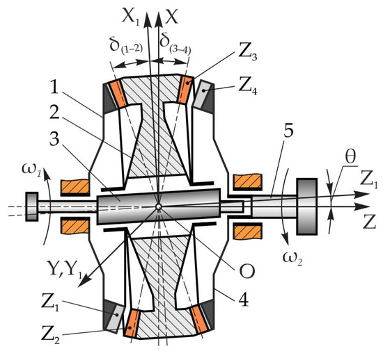
Figure 1.
The kinematic structure of the 2K–H-type precessional transmission [30].
According to [22], Robert Davison almost accidentally discovered the concept of nutation motion while tossing a coin on the table, which, with a decreasing rotation speed with rolling, performed a strange motion. This motion, with simultaneous rotation and rolling of the coin around three axes, represents spherospatial motion with a fixed point, which also includes nutation motion. This motion concept has been harnessed in the design of speed reducers called nutation bevel gears. The relative rotational motions in the nutational device depend on the number of teeth of the meshing gears and the difference in their numbers.
The authors of [22] believe that the nutation reducer is a totally innovative mechanical transmission developed in recent years, which is based on the principle of the interaction of teeth with nutation movement. They mention that the nutation gear reducer possesses the unique characteristics of single-stage motion reduction, tooth meshing occurs at very high angles, and the overall bearing capacity is higher. At the same time, the authors state that in the nutational transmission, the interaction of the teeth in the gear theoretically takes place with pure rolling, which indicates that the heat emanating between the tooth flanks should be lower and have higher energy efficiency. This article mentions that the NuGear gear transmission has only been experienced in virtual computer simulations [27]. Since the kinematics, structure, and relative movements of the teeth in “nutating” and “precessing” gears are absolutely identical, by extension, we can see that despite the authors’ claims regarding the novelty of the existence of “pure rolling” between the flanks of the teeth in the gearing in the "nutation" transmission, it is identical in the ”precession” transmission.
Also, the author of [42] in 1991, in the paper “The wonderful world of reduction gears created by Ion Bostan”, mentions that the idea of precession transmission is due to the coincidental observations made by Ph.D., Assoc. Prof. Ion Bostan in August 1977 while watching a light music concert in Sopot, Poland. The event was accompanied by spherospatial motion rolling with a fixed point of a gymnastic ring projected using a laser beam on a screen. When rolling the ring with different frequencies and amplitudes, due to the interference of the positions of the ring on the rolling surface, the formation of a variable profile was observed. These profiles as a whole led to the idea of the existence of variable convex–concave profiles dependent on the crankshaft revolutions and the amplitude of the oscillations, and thus, dependent on the parameters of the precession movement.
Thus, in 1983, the first invention patent was registered, Precessional Planetary Transmission S.U. 1020667 A, with priority 11 February 1981.
Precessional transmissions can be used in technical fields where it is necessary to transform and transmit movement and load to their drive mechanisms, including the following: machine building, fine mechanics, high-precision mechanical systems, submersible techniques, and movement between sealed spaces, etc.
The further development of precessional transmissions provides for the following: the modernization and optimization of the geometry and kinematics of the interaction of the teeth in the precession gearing, of the methods of generating the flank profiles of the teeth, and of the tribological aspects of the interaction of the teeth.
Also under research and development are magnetic precession transmissions including variable transmission ratios.
The remainder of the paper is structured as follows: Section 2. Kinematics of 2K–H-type precessional transmissions. Here, the influence of the number of teeth and their co-ratio on the range of the achieved transmission ratios is presented. Section 3. Mathematical model of precessional gearing with convex–concave contact of the teeth. Here, the algorithm for the design of the geometry of the teeth and the kinematics of their interaction is described. Section 4. Tooth contact geometry in multipair convex–concave gearing . In this chapter, the conditions for the existence of the multiplicity of tooth engagement and the influence of the configuration parameters on the shape of the flank profiles of the teeth are identified. Section 5. Geometry and kinematics of tooth contact in the gearings [30]. This chapter examines the interaction of teeth with spherospatial motion described by Euler kinematic and dynamic equations with the identification of sliding and rolling of tooth flank profiles at contact points. Section 6. Linear velocity of the contact point E1 on the tooth profile of the central wheel. Section 7. Linear velocity of the contact point E2 on the tooth profile of the satellite wheel. Section 8. Relative sliding between the tooth flanks is modified by shortening the heights. Section 9. Variation in the relative sliding between the conjugated flanks of the teeth. Section 10. Technological aspects. In this chapter, the procedures for generating the non-standard flank profiles of the gear teeth of the precessional gears are presented. The description of the methods and algorithms of the generation of the teeth of the wheels will be covered in articles dedicated to manufacturing technologies. Section 11. Application aspects; Section 12. Conclusions and recommendations; Section 13. Patents. International patents (US and German) are mentioned, which protect innovative technical solutions regarding the shape of flank profiles, ensuring the multiplicity of tooth engagement, and sliding and rolling of teeth in precessional gearings [33,34,35].
2. Kinematics of 2K–H-Type Precessional Transmissions
The technical solutions regarding the development of precessional transmission have been protected with over 220 inventions, including international patents (SUA, Germany, Russia) on their constructive functional structure, gear geometry, kinematics, and tooth geometry contact, as well as the technological processes for generating flank surfaces [31,32,33,34,35].
The 2K–H-type precessional transmission (PT) includes satellite wheel 2 with two toothed crowns with Z2 and Z3 as the number of teeth located, respectively, on the conical axoids under δ(1–2) and δ(3–4), which gears with the immobile 1 and mobile 4 central wheels, rigidly linked to driven shaft 5 (Figure 1). Satellite wheel 2 is mounted on the portion of motor shaft 3 that is inclined under the nutation angle θ, between central wheels 1 and 4 [30].
When crankshaft 3 rotates with the angular velocity ω1, satellite 2 performs spherospatial motion with a fixed point O, called the precession center.
The transmission ratio is determined by the following relation:
where Z2 and Z3 are the number of teeth in satellite wheel 2 and Z1 and Z4 are the number of teeth of central wheels 1 and 4.
The transmission ratio i achieved in the 2K–H-type transmission depends on the correlation of the numbers of geared teeth Z1(4) = Z2(3) ± 1.
Depending on the configuration of the tooth numbers Z1, Z2, Z3, and Z4 and others and their correlation, in transmissions with teeth gearings (Z1–Z2) and (Z3–Z4), if Z1 = Z2 − 1, Z4 = Z3 − 1, 15 ≤ Z1,2,3,4 ≤ 60, ±20 ≤ i ≤ ±3600 transmission ratios are ensured (Figure 2).
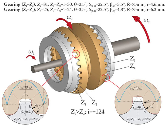
Figure 2.
The tooth profiles of the crowns of gearings (Z1–Z2) and (Z3–Z4) in the precessional gear transmission.
In the case of Z2 > Z3, the driving and driven shafts rotate in different directions (−), and in the case of Z2 < Z3 they rotate in the same direction (+).
Under these conditions, if Z1 = Z2 − 1 and Z4 = Z3 + 1, the 2K–H transmission ensures transmission ratios in the range of +8.3 ≤ i ≤ +30.3, 15 ≤ Z1,2,3,4 ≤ 60, and if Z1 = Z2 + 1 and Z4 = Z3 − 1, the 2K–H transmission ensures transmission ratios of −7.3 ≤ i ≤ −29.3.
According to the requirements of mechanical transmission consumers [30,37], the need for reducers according to the criterion of the transmission ratio i is expressed by a normal logarithmic curve with the maximum density in the area i = 32.1, and the ratios in the range i = (8–50) represent around 75% of their total used worldwide.
According to the transmission ratio density diagram shown in Figure 3, transmission ratios in the range ±8 ≤ i ≤ ±20 cannot be achieved with one-stage involute transmissions, but only with reducers with two to three stages, which leads (compared to those with one stage) to a sudden increase in the dimensions of the reducer, the number of components and, finally, to an increase in the cost of these transmissions.
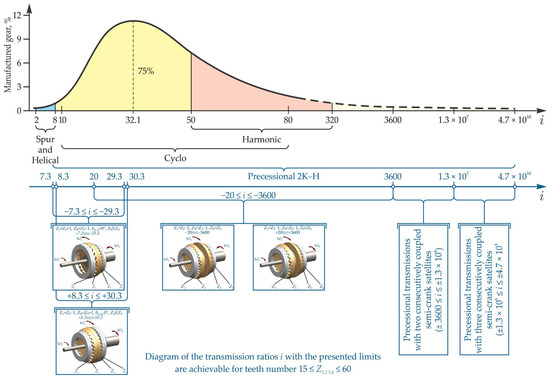
Figure 3.
The density of the transmission ratios of the mechanical transmissions used worldwide and the possible transmission ratios in the 2K–H precessional transmissions with toothed gears .
Unlike classical, cycloidal, or harmonic involute transmissions (Figure 3), 2K–H precessional transmissions ensure realization in a single stage, including small transmission ratios by choosing the number of teeth Z1, Z2, Z3, and Z4 and their correlation [30] (pp. 341–353) depending on the transmission ratio ±i required in the design specifications.
3. Mathematical Model of Precessional Gearing with Convex–Concave Contact of the Teeth
3.1. Designation of the Shape of the Satellite Tooth Profile and the Motion of the Reference Point
The kinematic relations of the interaction of the satellite with spherospatial motion with the central wheel of the precessional transmission are expressed by the Euler equations [30,37].
The theoretical developments [30,37] of the tooth–bolt gearing AB and the models and methods applied are also fully validated for the tooth–tooth gearing AD examined.
Precession gears with multipair convex–concave contact of teeth [30] can be developed in two directions: the first with gears formed by conical bolts engaged with teeth with convex–concave profiles (AB) and the second with toothed gearings (AD).
In order to create the convex–concave contact of the geared teeth with spherospatial motion, we state that the profile of the satellite teeth is denoted by the curve LENM, for example, in the circle arc of the radius r with the origin at point G (Figure 4), called the reference point of the satellite teeth.
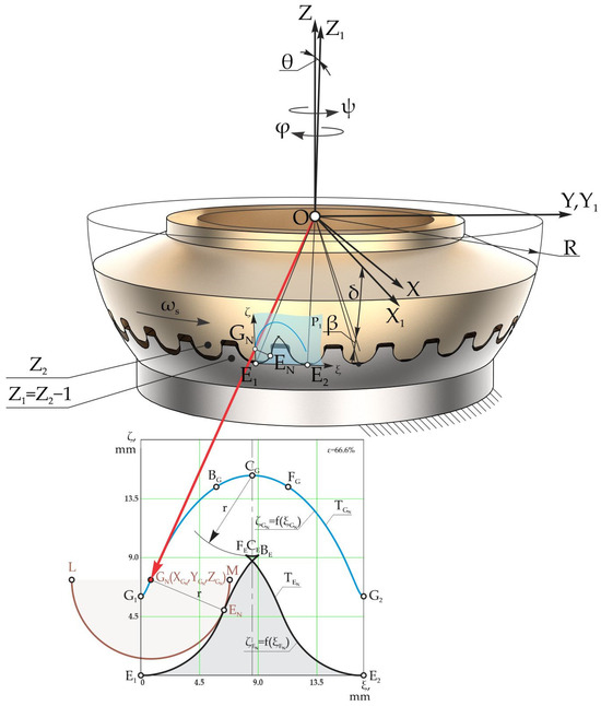
Figure 4.
The description of the trajectory of the motion of the origin G of the radius of the circle arc in the coordinates E1ξζ, projected on the plane P1 for gearing .
In the mobile coordinate system OX1Y1Z1 connected to the satellite, the position of the origin G of the radius of the circle arc is determined by the following coordinates:
where δ is the angle of the conical axoid.
In the Euler kinematic equations, taking into account (2) and the kinematic relation between the angles φ and ψ expressed by φ = −Z1ψ/Z2, we obtain the coordinates of the origin G of the radius of the circle arcs XG, YG, and ZG depending on the rotation angle of the crankshaft ψ in the fixed coordinate system OXYZ:
where R is the radius of the sphere originating in the center of the coordinate system O located in the precession center, δ is the angle of the conical axoid, θ is the nutation angle, ψ denotes the positioning angle of the crankshaft (of precession), and φ is the rotation angle of the satellite around its own axis.
The origin G of the radius of the circle arc, with which the teeth of the satellite are arbitrarily described, moves on the surface of the sphere with radius R with the origin in the precession center O, describing the trajectory expressed by the coordinates XG, YG, and ZG.
The trajectory of the motion of the origin G of the circle arc LENM from the sphere with radius R is projected on the plane P1 using the rules of spherical trigonometry [30] (p. 31). Thus, we can obtain the trajectory TG of the motion of the origin of the radius of the circle arc G on the plane P1, expressed by the dependence (Figure 4).
3.2. Determination of the Profile of the Central Wheel Teeth Expressed by the Motion Trajectory of the Tooth Contact Point
Knowing the trajectory of the motion of the origin of the radius of the circle arc G, expressed in the coordinates XG, YG, and ZG (Figure 5), we can determine the position of the contact point E of the satellite wheel tooth profile in a circle arc with the profile of the central wheel teeth.
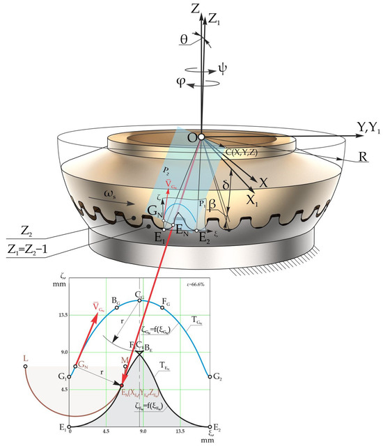
Figure 5.
Description of the profile of the central wheel teeth through the velocity vector VG of the origin G of the circle arc for gearing .
The contact point E of the satellite wheel teeth in a circle arc and the central wheel, for any angular position ψ of the crankshaft, is located at the distance of the radius r of the circle arc on the normal velocity vector VG from its origin at point G (Figure 5).
The family of contact points E obtained during a precession cycle 0 ≤ ψ ≤ 2πZ2/Z1 represents the profile of the central wheel teeth.
Next, to describe the profile of the central wheel teeth, we determined the velocity vector projections VG on the coordinate axes of the fixed system OXYZ.
For this purpose, we derived Equation (4) in time and obtain
where is the angular velocity of the crankshaft.
To determine the position of the contact point E of the teeth on the spherical surface, we identified the equation of a plane P2 drawn perpendicular to the velocity vector VG, passing through the precession center O and the origin of the radius of the circle arc G. The equation of the plane P2 can be written via the following expression:
where OG and OC are vectors that determine, respectively, the position of the reference point of the satellite wheel tooth G in a circle arc and the arbitrary point C of plane P2 with respect to the origin of the fixed coordinate system OXYZ (Figure 5).
The vector product is expressed as a third-order determinant and, after opening it with the elements of the first line, we obtain the following:
where XG, YG, and ZG are the coordinates of the reference point G of the satellite teeth in a circle arc, and X, Y, and Z are the coordinates of arbitrary point C on plane P2.
Analogously, we described the vector equation ; using (6), we obtain
and after opening, we obtain the following equations:
Equation (10) results from (8) and (9) and can be adopted as the equation of plane P2 in Figure 5.
In order to identify the coordinates of the contact point E of the profile of the satellite teeth in a circle arc with the profile of the central wheel teeth, we considered that the point E belongs simultaneously to plane P2 and the sphere with the radius R. For these reasons, the coordinates of point E satisfy the equation of plane P2, for which reason we can write the following equation:
The contact point of teeth E also belongs to the sphere with the radius R; that is, its coordinates satisfy its equation:
In Figure 4, the angle between the position vectors of the reference point of the tooth in the circle arc OG of the satellite wheel and the position vector of the contact point E of the teeth OE represent the taper angle β of the teeth of the satellite in a circle arc, resulting in the following:
or
Using Equation (14), we determined
To determine the coordinate YE of the contact point of teeth E, we substituted (15) into (11) and obtained
and by substituting (16) into (15), we obtained the expression of coordinate XE of the following contact point:
where
Substituting (16) and (17) into (12) and solving the equation obtained with respect to the coordinate ZE of the contact point E, we obtain the following [30,37]:
It is worth mentioning that the curve of the tooth profile of the central wheel is equidistant to the motion trajectory of the origin G of the radius of the circle arc, and for any rotation angle ψ of the crankshaft, it must fulfill the condition ZE < ZG.
After some transformations of expression (19), the coordinate ZE can be determined by the following relation:
The relations (16), (17), and (20) determine the coordinates XE, YE, and ZE of the contact point E of the teeth, the set of which in a precession cycle represents the profile of the central wheel teeth placed on the sphere.
The precessional gear being conical, with the extensions of the generators intersected in the precession center, it is appropriate to examine the profile of the teeth in the normal section—for example, in plane P1 drawn through points E1 and E2 perpendicular to plane OE1E2 (Figure 5).
The coordinates XE, YE, and ZE of the points E1 and E2 on the profile of the teeth on the sphere are determined from the relations (13), (13), and (20) for the precession angles ψ = 0° and ψ = 2πZ2/Z1, corresponding to a precession cycle, and the equation of the plane from the following condition:
where EN is a point on plane P1.
The vector products in (21) are calculated according to the matrix theory:
and
where
Substituting (22) and (23) into (21), we obtain the equation of plane P1:
Using the rules of spherical trigonometry, we projected the profile of the teeth from the sphere with radius R on the plane P1, in turn expressed by the coordinates of the point EN of intersection with the family of the contour lines passing through the precession center O and community of points N from the tooth profile on the sphere. The projector–director equation in the shape of a straight line, passing through the precession center O and the points EN, is presented by the following expressions:
Using the equations of plane P1 (24) and contour line (25), we obtain
Solving Equation (26) depending on X, we obtain
where
The coordinates YEN and ZEN were determined from relation (25).
To design the profile of the central wheel teeth in two coordinates ξ and ζ in the plane P1, we drew the coordinate system E1ξζ with the origin at point E1, whose axis E1ξ passes through point E2 (Figure 5). Using the coordinates XEN, YEN, and ZEN, we moved to the coordinates ξ and ζ using the following relations:
where
The expressions in (28) represent the coordinates of the points of the curve, whose family constitutes the profile of the central wheel flanks projected on the plane P1, expressed in parametric form by varying the precession angle from ψ = 0° up to ψ = 2πZ2/Z1.
We next aimed to identify the peculiarities of the contact of the precessional satellite teeth with the profile designated in a circle arc and the peculiarities of the central wheel teeth with the profile described by the coordinates ξ and ζ. Thus, we determined the motion trajectory in plane P1 with the origin G of the radius of the circle arcs at a precession cycle 0 ≤ ψ ≤ 2πZ2/Z1.
For this, we used XGN, YGN, and ZGN to note the coordinates of the points of intersection with the plane P1 of the contour line passing through the precession center O and the origin G of circle arcs. The coordinates XGN, YGN, and ZGN were determined by replacing the coordinates XE, YE, and ZE with the coordinates XG, YG, and ZG. Thus,
where
To design the motion trajectory of the origin G of the circle arcs in 2D, we moved from the coordinates XGN, YGN, and ZGN to the Cartesian coordinates and using the following relations:
where
The function (33) is the projection of the motion trajectory of the origin G of the circle arcs on plane P1, and the function (28) represents the profile of the central wheel teeth designed on plane P1.
Figure 6 presents profilograms of the teeth of the toothed gear (Z1–Z2) with the parametric configuration Z1 = 21, Z2 = 22, r = 5.5 mm, θ = 3.5°, δ(1–2) = 22.5°, and R = 75 mm (a) and the toothed gear (Z3–Z4) with the parametric configuration Z3 = 31, Z4 = 32, r = 4.5 mm, θ = 3.5°, δ(3–4) = 22.5°, and R = 75 mm in the 2K–H precessional reducer with the transmission ratio i = −67.2.
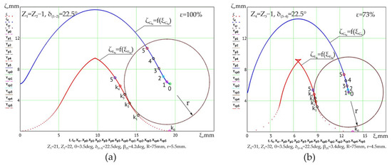
Figure 6.
The reference profilograms of the tooth flanks of the central wheels for the 2K–H precessional toothed gear, i = −67.2, with the reference multiplicity ε = 100% (a) and ε = 73% (b).
The profiles of the central wheel teeth are presented by the functions constructed according to the relations in (27), and those of the teeth of the satellite wheel are prescribed in a circle arc with the radius r. The reference multiplicity in the gear (Z1–Z2) (Figure 6a) is 100%, and that in the gear (Z3–Z4) (Figure 6b) is 73%.
The points k0, k1, k2,…, ki on the curve represent the contact of the tooth flanks of the central imaginary wheel in the real gear with circle arcs with the origins of the radii appropriately placed at points 0, 1, 2, …, i on the curve . The contact points k0, k1, k2,…, ki on the curve , as well as the origins of the radii of curvature of the circle arcs 0, 1, 2,…, i on the curve , correspond to the crankshaft position angles determined by the relation , where i is the order number of the contact of the geared tooth pairs.
Figure 6 shows that the sliding velocity between the tooth flanks and the difference in the radii of curvature at the contact points k0, k1, k2,…, ki are variable depending on the precession angle ψ.
Remark 1.
The trends in variation in the relative sliding velocity and the trends in the difference in the radii of curvature of the conjugated profiles represent two determinant aspects of the increase in the load bearing of the tooth contact and the increase in the mechanical efficiency of the AD-toothed precessional gear.
The profile of the central wheel teeth in the normal section was designed in the CAD/CAM/CAE modeling system SolidWorks and CATIA V5.
4. Tooth Contact Geometry in the Multiple-Pair Convex–Concave Gearing
Based on the analysis of the interaction of teeth in the precessional gearing with spherospatial motion with a fixed point, its bearing capacity depends on three factors, namely:
- The geometry of the convex–concave contact of teeth, according to solid deformable body mechanics, provides a bearing capacity inversely proportional to the difference in tooth flank curvatures, i.e., the smaller the difference in tooth flank curvatures, the greater the contact bearing capacity for the same regime, material, lubricant, and lubrication parameters.
- The variability of the profile of the teeth of the central gears according to the parametric configuration [Zg − θ, ±1] provides at one precession cycle , a lot of ki contacts, with the distance between neighboring contacts equal to the angular pitch [35] (p. 9).
- Given the condition stated on p. 2, it follows that for the same crankshaft coordinate, for example, (Figure 7b) or (Figure 7c) simultaneously in the gearing, there are eight pairs of teeth (with profiles cut by modification determined by the calculation of the teeth’s resistance to contact pressure), with four pairs having contact on the active profile and four pairs having contact on the passive profile of the teeth.
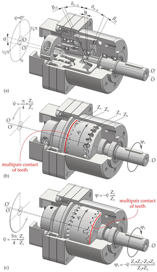 Figure 7. Conjugation of the teeth (Z1–Z2) and (Z3–Z4) in gears with the correlation of the numbers of teeth Z1 = Z2 − 1 and Z4 = Z3 − 1 and the angles of the conical axoids δ(1–2) = δ(3–4) = 22.5° depending on the precession angle ψ: angular positioning of the driving shaft ψ = 0° (a); (b) and (c).
Figure 7 shows the evolution of the conjugation of the teeth (Z1–Z2) and (Z3–Z4) in the gears , with the correlations of the tooth numbers Z1 = Z2 − 1, Z4 = Z3 − 1 and the angles of the conical axoids δ(1–2) = δ(3–4) = 22.5° depending on the precession angle ψ.
In order to reduce frictional sliding between the flanks, in the precessional transmission with the gear , the teeth are modified by shortening their height so as to keep simultaneous gearing up to three or four pairs of teeth with contacts k0, …, k4 (Figure 8, Figure 9 and Figure 10) located on the active side of the gear area.
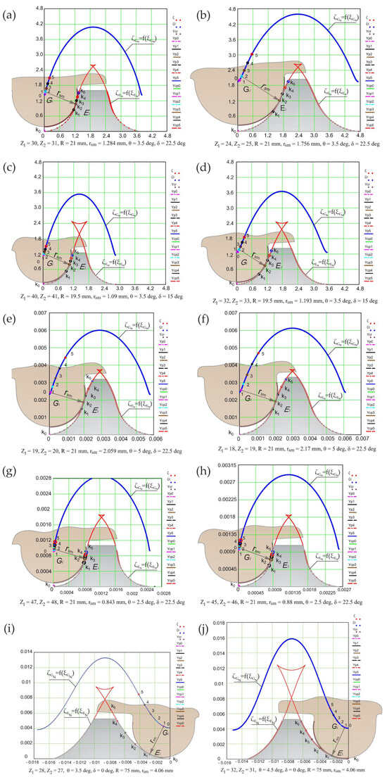
Figure 8.
Flank profiles modified according to the dispersion of the contact points ki of the conjugated teeth simultaneously in the precessional gearing (a) with Z1(4) = Z2(3) − 1 (a–h) and with Z1(4) = Z2(3) + 1 (i,j).
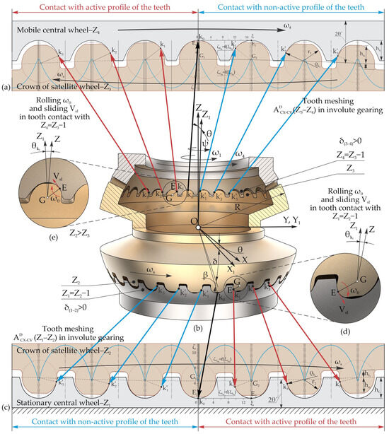
Figure 9.
The relative sliding Vsl and rolling ωθ of the flank profiles (d,e) at the contact points ki of the conjugated teeth in the gearing (a,c), with Z1 = Z2 − 1, Z4 = Z3 − 1, δ(1–2) > 0°, δ(3–4) > 0°, and Z2 > Z3 or Z2 < Z3 (b).
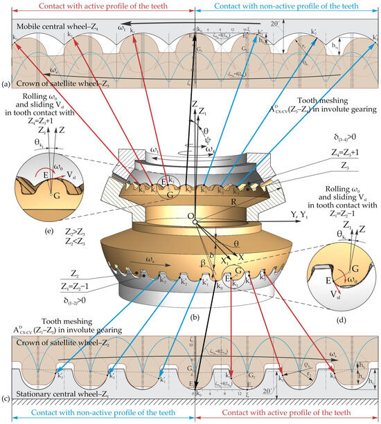
Figure 10.
The relative sliding Vsl and rolling ωθ of the flank profiles (d,e) at the contact points ki of the conjugated teeth in the gearing (a,c), with Z1 = Z2 − 1, Z4 = Z3 + 1, δ(1–2) > 0°, δ(3–4) > 0°, and Z2 > Z3 or Z2 < Z3 (b).
Therefore, if a gear is designed with four pairs of teeth engaged in transmitting the load through the contacts k0, …, k4, there will be eight pairs of teeth in the gear area, of which four pairs are passive (do not transmit load). In this case, when rotating the driving shaft with the angle , the eight pairs of teeth in the gear area will rotate at an angle between two neighboring teeth. Each pair of teeth will go through the gearing phase of the preceding tooth pair (Figure 9 and Figure 10).
Figure 7a shows the positioning of the pairs of teeth conjugated simultaneously in the gears , with the precession angle ψ = 0°. When rotating the crankshaft with the angle , the positioning of the pairs of teeth conjugated simultaneously in the gears (Z1–Z2) and (Z3–Z4) is shown in Figure 7b, and up to the angle , the positioning of the pairs of teeth conjugated simultaneously, (Z1–Z2) and (Z3–Z4), is shown in Figure 7c.
The energy losses in the precessional transmission with the toothed gear , with the reducer operating mode, are estimated based on the evolution of the relative friction speeds between the tooth flanks, and the bearing capacity is based on the evolution of their contact geometry.
Figure 8 shows examples of tooth profiles modified according to the dispersion of the contact points ki of the simultaneously conjugated flanks in the gears with the correlation Z1 = Z2 − 1 (Figure 8a–h)) and Z1 = Z2+1, respectively, (Figure 8i,j) for configuration parameters [Zg − θ, ±1] selected randomly and variably (computer-designed according to Equations (28) and (33)) [37].
In the presented profilograms, the functions and represent, respectively, the trajectory of the motion of the origin of the circle arc G of the profile of the satellite wheel teeth and the profile of the central wheel teeth, expressed in the parametric equation of point E in cartesian coordinates, with the variation of the precession angle from ψ = 0° to ψ = 2πZ2/Z1 [34,35].
The profiles presented in Figure 8a–h are recommended for the elaboration of precessional transmissions with a reducer operation regime and with a transmission ratio in the range of ±20 ≤ i ≤ ±3600. Those in Figure 8i,j are for precessional transmissions with a transmission ratio of ±7.3 ≤ i ≤ ±30.3 and a reducer operation regime if the angle of the conical axoid δ1(4)–2(3) = 0° or a multiplier operation regime if δ1(4)–2(3) > 0°.
The contact points k0…k5 (Figure 8) of the flanks of the teeth in the gear area are transposed on the profile of the teeth of the central wheels according to ψ, corresponding to each pair of teeth simultaneously conjugated.
5. Geometry and Kinematics of Tooth Contact in the Gearings
It is important to note that in precessional gearings with convex–concave profiles, the interaction of the teeth occurs in spherospatial motion, with relative sliding Vsl in the contacts of simultaneously conjugated tooth pairs ki and, at the same time, with relative rolling ωθ around the contact points ki (Figure 9 and Figure 10).
The relative rolling ωθ of the profiles of the teeth of the satellite wheel crown with respect to the profiles of the teeth of the central wheel occurs around their contact points ki, which predominantly depend on the value of the nutation angle θ of the spherospatial motion and the angular pitch between neighboring contact points k0–k1, k1–k2, k2–k3, etc.
The relative rolling ωθ of the flank profiles of the vector-conjugated teeth is contingent on the angular rolling direction ωθ of the flank profiles, either aligned or counter to the linearly traveling direction of the contact points ki of the flanks of the simultaneously conjugated tooth pairs, with relative sliding Vsl. It has been observed that the contact point ki of the flanks of the simultaneously conjugated teeth travels along the active profile of the teeth on the central wheels, progressing from the root toward their tips (Figure 9).
By analyzing Figure 9 and Figure 10, it was determined that the angular coordinates of the contact points of the flank profiles of the simultaneously conjugated teeth are expressed through the angular pitch of the contact point, as defined by the relationship , where i = 0, 1, 2, 3… is the order number of the conjugated tooth pairs, starting with the pair of teeth at contact point k0.
While analyzing the kinematics of the contact points ki of the simultaneously conjugated teeth in the gears shown in Figure 9d,e, it is evident that the spherospatial interaction of the flank profiles causes the angular rolling of the conjugated flanks ωθ around the contact points E, with their migration in the direction or counter to the direction of the relative sliding vector between the flanks Vsl. This ensures an increase or decrease in profile rolling and energy loss between the conjugated flanks, respectively.
Thus, in the precessional transmission with toothed gear , where the ratio of the number of teeth of the conjugated wheels is Z1 = Z2 − 1, Z4 = Z3 − 1, δ(1–2) > 0°, δ(3–4) > 0° and Z2 > Z3 or Z2 < Z3, as the precession angle increases within the range of , tooth interaction occurs with the presence of the frictional forces with relative sliding Vsl at the contact points ki, migrating from the roots toward the tips of the teeth. Simultaneously, there is a reciprocal rolling of the flank profiles ωθ around the contact points ki, with migration in the same direction. This leads to an increase in the degree of rolling ωθ of the conjugated tooth flanks relative to the sliding with friction between the simultaneously conjugated tooth flanks and, consequently, an increase in the mechanical efficiency of the transmission.
Figure 10 shows the relative rolling ωθ and sliding Vsl of the tooth flank profiles at the contacts k0, k1, k2, k3… and … for the toothed gearing with Z1 = Z2 − 1, Z4 = Z3 + 1, δ(1–2) > 0°, δ(3–4) > 0° and Z2 > Z3 or Z2 < Z3, operating under the multiplier regime.
The functioning of the 2K–H precessional transmission in a multiplier (or differential) regime can be efficiently achieved under the following conditions:
- The correlation of the number of teeth in one of the gears , is either Z1 = Z2 + 1, Z4 = Z3 − 1 or Z1 = Z2 − 1, Z4 = Z3 + 1, and the angle of the conical axoid δ(1–2) > 0°, δ(3–4) > 0° and Z2 > Z3 or Z2 < Z3;
- The satellite wheel is installed as axially floating between the stationary and mobile central wheels, tangentially sliding in relation to the central gears;
- The parametric configuration [Zg − θ, +1] must ensure a pressure angle between the teeth in one of the engagements (Z1–Z2) or (Z3–Z4), αω > 45° (Figure 10).
The rotational motion of the shaft and mobile central wheel with the profile angle of the teeth αω > 45°, through the effect of the inclined wedge, turns into the spherospatial motion of the satellite wheel. As a result, the teeth Z2 and Z3 engage accordingly with the teeth Z1 and Z4 of the immobile central wheel, fixed in the housing, and the mobile central wheel, mounted on the driving shaft, thus achieving the multiplication ratio i = −Z2Z4/(Z1Z3–Z2Z4).
So, in the tooth meshing (Z1–Z2), the rolling of the teeth ωθ around their contact points ki causes them to travel in the direction of the sliding of the flanks Vsl. On the other hand, in the tooth meshing (Z3–Z4), the rolling of the teeth around their contact points ki causes them to travel against the direction of relative sliding, with friction between the flanks.
The relative sliding with friction in the contacts of the teeth ki, and the relative rolling of the flanks of simultaneously conjugated teeth, is illustrated in Figure 3 and Figure 4, where the following are true:
Remark 2.
In precessional gearing
, teeth interact with spherospatial motion, with the presence of relative sliding Vsl at the contact points ki of flank profiles and, simultaneously, with relative rolling ωθ around the contact points ki.
Remark 3.
The relative sliding Vsl depends on the difference in linear velocities at the contacts of teeth Z1 and Z2 (or Z3 and Z4), and quantitatively depends on the parameters of the [Zg − θ, ±1] configuration.
Remark 4.
The vector of relative velocity Vsl between the conjugated tooth flanks is tangentially oriented to the flank profiles at the contact points ki, which, as the precession angle increases, travel from the root to the tip of the teeth.
Remark 5.
The relative rolling ωθ of the flank profiles of simultaneously conjugated teeth around the rolling centers E (contact points) depends on the nutation angle θ and the angular stage of the contact points ki on the conjugated flank profiles.
Remark 6.
In cases where the direction of migration of the rolling center E (contact points) of the flank profiles aligns with the vector of relative sliding Vsl, the relative rolling ωθ compared to the relative sliding increases, reducing energy losses in the meshing of the teeth and vice versa.
6. Linear Velocity of the Contact Point E1 on the Tooth Profile of the Central Wheel
The interaction of conjugated teeth in precessional gearing takes place with the presence of relative sliding Vsl between the flanks.
Both the geometric shape of the tooth contact and the kinematics of the contact point depend on the value configuration of the geometric parameters of the gear, noted by [Zg − θ, ±1], among which are Z1, Z2, δ, θ, and β, and the correlation of teeth Z1 = Z2 − 1 or Z1 = Z2 + 1.
The position vector of the contact point E1 of the conjugated teeth, which belongs to the profile of the central wheel tooth (Figure 11), is identified through the vector equation:
where and , where r is the position vector of the point E1 relative to the point G2 and has a modulus equal to the radius of curvature of the profile of the satellite teeth with a circle arc profile, and and are the collinear position vectors of the origin of the radius of curvature of the teeth in the circle arc of the satellite on the sphere and in the direction OG (Figure 11).
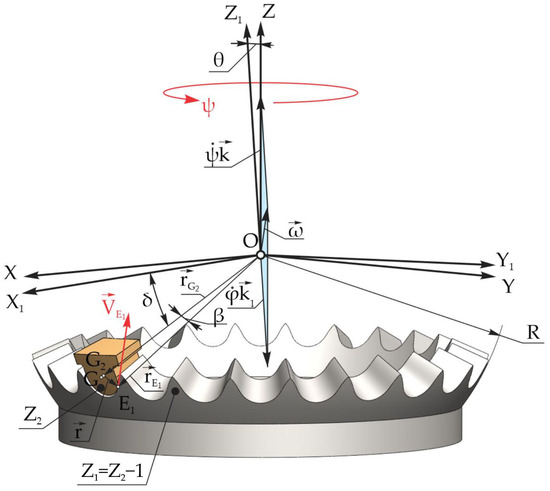
Figure 11.
The contact point velocity vector position on the profile of the central wheel tooth.
The position vector of the origin of the radius of curvature can be expressed by the coordinates , and :
and the velocity vector of the point G2 is .
Here, , , and are the projections of the velocity of point G2 on the axes of the fixed coordinate system OXYZ.
To determine the position vector of the contact point E1 (Figure 11), we noted the axis OG the point G2, located in its normal section passing through the contact point E1, and we identified the trajectory of its motion in the fixed coordinate system OXYZ expressed by coordinates , , and depending on ψ:
where β is the tip angle of the satellite tooth profile.
The projections on the axes OX, OY, and OZ of the velocity vector of the are as follows:
where Z1 is the number of teeth of the central wheel; Z2 is the number of teeth of the satellite; and is the angular velocity of the crankshaft, which, given its rotation frequency n = 3000 rpm, is ω = 2πn s−1.
We can denote by a the vector product in (37):
where
Using the notation in (42), we obtain the vector r:
The vector derivative in relation to time was determined from the following relation:
where was introduced:
The projections on the axes OX, OY, and OZ of the acceleration of point G2 are defined by the following expressions:
To determine the linear velocity of the contact point of the conjugated teeth, which belongs to the profile of the central wheel teeth E1, we derive (37) with respect to time and obtain the following:
The projections of the vector on the axes OX, OY, and OZ are determined by the following expressions:
The modulus of the velocity of the contact point E1 is determined from
7. Linear Velocity of the Contact Point E2 on the Tooth Profile of the Satellite Wheel
The spherical motion of the satellite wheel rigidly connected to the mobile coordinate system OX1Y1Z1 in relation to the fixed system OXYZ can be described by analytical relations.
The vector diagram in Figure 12 shows the positioning of the velocity vector of the contact point E2, which belongs to the profile of the satellite wheel tooth, with compliance with the following condition:
where
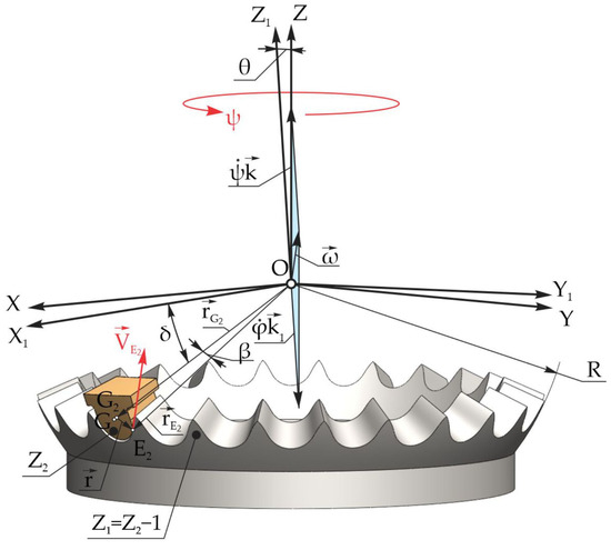
Figure 12.
The positioning of the velocity vector of the contact point on the profile of the satellite wheel tooth.
To determine the coordinates of the contact point E2, we expressed the position of the satellite wheel using the unit vectors i1, j1, and k1 depending on the unit vectors i, j, and k and Euler’s angles ψ, θ, and φ.
The coordinates of the contact point E2 on the profile of the satellite wheel teeth in the mobile coordinate system OX1Y1Z1 were determined according to the following expressions:
The projections of the velocity vector of the point E2 on the profile of the satellite wheel tooth were calculated by deriving in relation to time the coordinates , , and , which were dependent on the coordinates , , and Euler’s angles.
Thus, we obtain the expressions for the projections of the velocity of the point E2 on the coordinate axes OX1, OY1, and OZ1.
Using the relation (54) for the calculation of the projections of the velocity of the contact point E2, we determined the modulus of the velocity of the contact point E2 on the profile of the satellite tooth according to the following relation:
The relative sliding between the tooth flanks in the contact E is determined by the difference between the linear velocities of the contact points on the profiles of the central wheel tooth and the satellite wheel tooth , depending on the positioning angle of the crankshaft ψ, which is defined as follows:
8. Relative Sliding between the Tooth Flanks Is Modified by Shortening the Heights
The relative sliding with friction between the flanks of the conjugated teeth in the precessional gearing varies within a precessional cycle depending on the angular coordinate of the contact point of each pair of simultaneously conjugated teeth, which, in turn, depends on the precession angle ψ of the crankshaft and is determined from relation (58).
Figure 13a shows the variation in the relative sliding velocity Vsl depending on the precession angle ψ for the precessional gearing with the tooth correlation Z1 = Z2 − 1 and the angle of the conical axoid δ = 22.5°. Figure 13b shows the correlation Z1 = Z2 + 1 and δ = 0°, and Figure 13c shows the correlation Z1 = Z2 + 1 and δ = 22.5°.
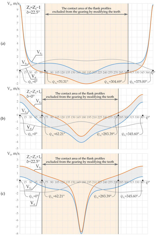
Figure 13.
The linear velocities in contact , and the relative sliding velocity between the teeth in the precessional gearing with the correlation of the teeth Z1 = Z2 − 1, Z1 = 24, and δ = 22.5° (a); Z1 = Z2 + 1, Z1 = 25, and δ = 0° (b); and Z1 = Z2 + 1, Z1 = 25, and δ = 22.5° (c).
It should be noted that in the toothed precessional gearing , the reference frontal multiplicity εa is up to 100% of the pairs of simultaneously conjugated teeth.
For the same positioning of the crankshaft experienced through the precession angle ψ, it is necessary for the gearing to contain a certain number of pairs of teeth at the same time, spaced from each other by the angular pitch .
Given the analysis of the variation in the relative velocities between the flanks of the conjugated teeth shown in Figure 13a–c, the minimum relative sliding dominates in the contacts of the conjugation of the profiles of the teeth of the central wheels in the foot area with the top profiles of the teeth of the satellite wheel.
For these reasons, in order to reduce the energy losses in the toothed gearings , modifying the teeth by shortening their height by cutting the tips of the central wheel teeth is proposed [33,34]. Thus, shortening the height of the teeth by cutting off their tips ensures that a sufficient number of pairs of teeth (determined from the calculation of the resistance of the teeth to the contact pressure σH) are kept in gearing.
For example, for the gearing with the correlation Z1 = Z2 − 1 and δ = 22.5°, four pairs of teeth with an angular pitch extend to the crankshaft precession angle ψ = 62.4° for the contacts on the active profiles of the teeth. For gearings with Z1 = Z2 + 1 and δ = 0° or δ = 22.5°, four pairs of teeth extend to the precession angle of the crankshaft ψ = 55.2°.
To investigate the energy losses in gearings generated by the relative sliding between the planes of the teeth Vsl, precessional transmissions were designed and manufactured with wheels made of various material couplings, namely, 4041 steel central wheels and PEEK plastic satellite wheels or PEEK plastic central wheels and 4041 steel satellite wheels.
Figure 14a shows the variation in the velocity modules and at the contact points E1 and E2 on the tooth profile of the satellite wheel and on the profile of the central wheel tooth, respectively, and the sliding velocity Vsl with friction at point E depending on the precession angle ψ for the gearing Z1 = Z2 − 1 and δ(1–2) = 22.5° (Z1 = 24, Z2 = 25, θ = 3.5°, r = 6.27 mm, R = 75 mm).
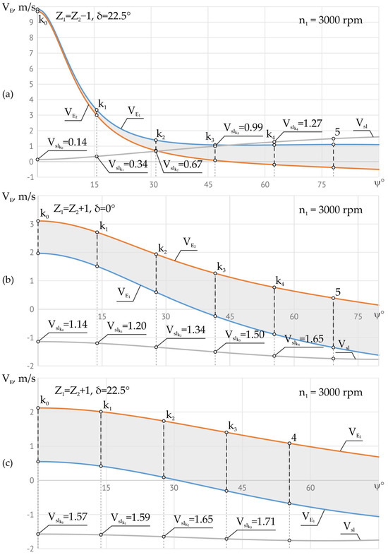
Figure 14.
The linear , , and sliding velocities in the contact ki depending on ψ for Z1 = Z2 − 1 and δ = 22.5° (a); Z1 = Z2 + 1 and δ = 0° (b); and Z1 = Z2 + 1, Z1 = 25, and δ = 22.5° (c).
For the case where the crankshaft rotates with the frequency of revolutions n1 = 3000 rpm, we obtain the linear and , and sliding Vsl velocities, as shown in Figure 14a. The mechanical efficiency of the gear is the expression of the energy losses generated by the sliding friction forces between the conjugated flanks, and the bearing capacity of the convex–concave contact results from the size and the difference in their radii of curvature.
For these reasons, the influence of different parametric configurations [Zg − θ, ±1] on the contact kinematics and geometry was examined, distinguished from each other only by the correlation Z1 = Z2 ± 1 and the angle of the conical axoid δ ≥ 0°.
The analysis of the contact kinematics of the teeth in the gearings [35] shown in Figure 14a–c shows that in the gearing corresponding to the parametric configuration [Zg − θ, −1] with the correlation of the number of teeth Z1 = Z2 − 1 and the angle of the conical axoid δ = 22.5° (Figure 14a), the relative sliding velocity Vsl, in contacts k0, k1, k2, and k3 is relatively lower, which implies an opportunity to use this gearing in the design of precessional gears with a reducer operation regime. At the same time, the gearing with the configuration [Zg − θ, +1] and the angle of the conical axoid δ > 0° (Figure 14b) is recommended to be used in transmissions with a multiplier operation regime and angle of the conical axoid δ = 0° in the reducer, with small transmission ratios contained in the ranges −7.3 ≤ i ≤ −29.3 for δ(1–2) = 0°, Z1 = Z2 + 1 and in the range +8.3 ≤ i ≤ +30.3 for δ(3–4) = 0° Z3 = Z4 + 1.
9. Variation in the Relative Sliding between the Conjugated Flanks of the Teeth
The geometry of the contact and the kinematics of the contact point of the conjugated teeth in the gear (Z1–Z2) or (Z3–Z4) are dependent only on the configuration [Zg − θ, ±1] of the respective gear, i.e., the relative sliding between the teeth in gearing (Z1–Z2) have constant values for any other gearing (Z3–Z4) with which it conjugates, and vice versa for the same crankshaft speed.
Figure 15 shows the influence of the configuration parameters [Zg − θ, ±1] on the relative sliding speed from the precessional transmissions, with the transmission ratios i = −124, i = −164, i = +15, and i = −14. Also, for the more complex comparative analysis, the relative slips in the gears with the ratios i = −360, i = −1080, i = −2115 are presented.
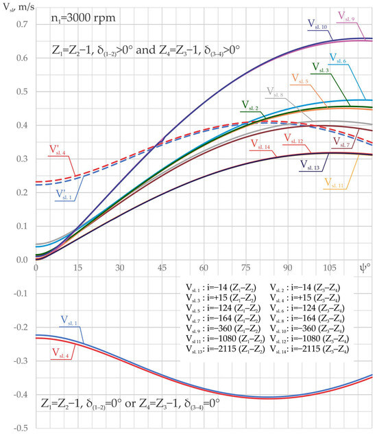
Figure 15.
The influence of configuration parameters [Zg − θ, ±1] on the relative sliding velocity Vsl between conjugated flanks of teeth.
The analysis of Figure 15 demonstrates that the evolution of the relative sliding Vsl depends on the correlation Z1(4) = Z2(3) − 1 or Z1(4) = Z2(3) + 1 of the numbers of teeth of the geared wheels. For the correlation of the number of teeth Z1(4) = Z2(3) − 1, the relative sliding velocities are presented by the curves , and , which increase from the minimum in the pair of teeth conjugated in contact k0 (Figure 15) to the maximum in the pair of teeth conjugated in contact k4.
For the correlation Z1(4) = Z2(3) + 1, the relative sliding velocities are presented by the curves and , which indicate that in the pairs of teeth with the angular coordinate up to ψk = 40°, the relative sliding is higher than in the case of the correlation Z1(4) = Z2(3) − 1.
The variation in the sliding velocity modules and depending on ψk is shown by dotted curves, which facilitates the analysis of the sliding velocities in the gears with the correlation Z1(4) = Z2(3) + 1 compared to the sliding velocities for the correlation Z1(4) = Z2(3) − 1.
In precessional transmissions, the relative sliding speeds at the contact points of the profiles are lower than involute, cycloidal, and Wildhaber–Novicov gears.
10. Technological Aspects
The following procedures were developed to manufacture wheels of precessional gearings :
- The generation of tooth flanks via spatial tumbling–rolling with a truncated cone-shaped tool (Figure 16) protected by patents [30,32,36], with a peripherally profiled disk-shaped tool (Figure 17) [43,44] and with a cylindrical tool on multi-axis machine tools (Figure 18);
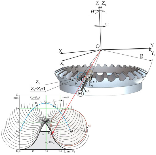 Figure 16. The process of generating teeth with variable convex/concave and concave/concave profiles via spatial tumbling–rolling with a “cone trunk”-shaped tool.
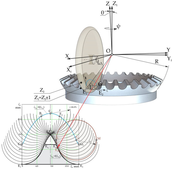 Figure 17. Procedure for generating teeth with a convex/concave profile via spatial tumbling–rolling with a tool in the shape of a “peripherally profiled disk”.
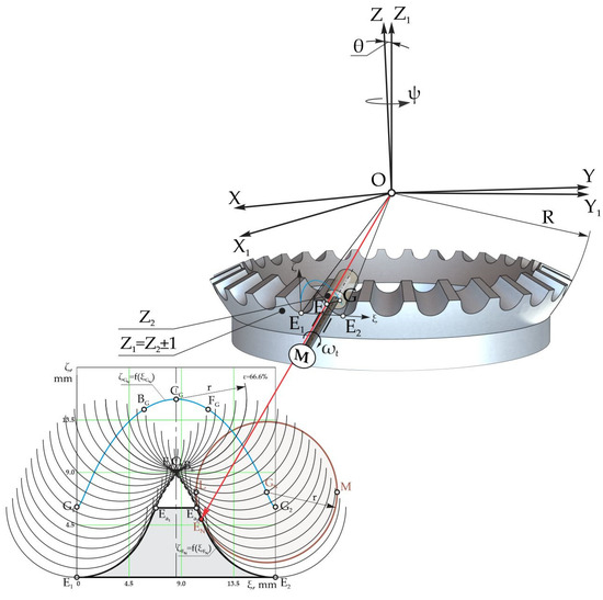 Figure 18. The main scheme of the generation process of teeth with a convex/concave profile with a cylindrical tool.
 - Using CNC numerically controlled machine tools;
- Plastic injection under pressure;
- Sintering with metal powder pressing.
11. Application Aspects
11.1. Precessional Transmissions with Satellite Wheels Mounted Axially Floating on the Crankshaft with Concurrent Axes in the Precession Center (Wheels Manufactured on CNC Machine Tools)
Figure 19 shows the 2K–H precessional transmission with the ratio i = −164 in the axial section with conjugated wheels in gearing with straight teeth geared in multipair convex–concave contacts with Z1 = 40, Z2 = 41, Z3 = 33, Z4 = 32, θ = 3.5°, δ(1–2) = 15°, β(2) = 3.2°, δ(3–4) = 15°, and β(3) = 3.5°.
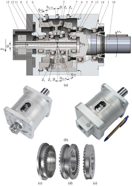
Figure 19.
2K–H low-power precessional transmission (i = −164) with gears with straight teeth and a satellite wheel mounted axially floating on the crankshaft, as well as concurrent axes in the precession center under the nutation angle θ: general drawing (a); samples of the transmission (b); central wheels (c,e); and satellite wheels (d).
Satellite wheel 2 is mounted axially floating in radial–axial bearings 6 and 7 on the inclined portion of crankshaft 5 with concurrent axes in the precession center under nutation angle θ with respect to the common axis of radial bearings 8 and 9. Immobile central wheel 3 is fixed in cover 11, centered axially with housing 1. Central mobile wheel 4 is mounted on the flange of driven shaft 10, and satellite wheel 2 in common with crankshaft 5 is installed axially floating in radial bearings 8 and 9.
The precessional transmission with a satellite wheel mounted axially floating on the crankshaft with concurrent axes in the precession center under the nutation angle θ is recommended in the case of power transmissions with high transmission ratios, where the forces in the gears are relatively large. In these cases, in order to reduce the stresses of the transmission shafts, especially of the bearings, using the tooth profiles of the central wheels with small pressure angles between the conjugated flanks αw < 20° is recommended.
Due to the spherospatial interaction of the teeth of satellite wheel 2 with the teeth of central wheels 3 and 4 located laterally, with pressure angles between the flanks αw < 20° and the installation of the axially floating precessional node, a reduction in the load in the kinematic couplings is ensured, as well as a reduction in the precision restrictions of the manufacturing of the component parts of the precessional node.
Figure 19b shows samples of the 2K–H precessional transmissions with the transmission ratio i = −164 achieved in gears with straight teeth in multipair convex–concave contact, in which satellite wheel 2 is mounted axially floating on crankshaft 5 with concurrent axes in the precession center under nutation angle θ.
Figure 19 shows the central wheels (c), (e) and the satellite wheel (d) manufactured from steel 4140 using CNC machine tools at Gleason Corporation, USA.
For example, the gearing with Z1 = 40, Z2 = 41, Z3 = 33, and Z4 = 32 ensures the transmission ratio i = −164 with the rotation of the driving and driven shafts in the opposite direction, and in the case of a change in the placement of the central wheels, i.e., Z1 = 32, Z2 = 33, Z3 = 41, and Z4 = 40, the transmission ratio i = +165 with the rotation of the driving and driven shafts in the same direction.
Figure 20 shows a 3D view of the precessional transmission with gearing with straight teeth and a satellite wheel mounted by axially floating on the crankshaft with concurrent axes in the precession center (a) and an experimental sample of the servo-gearmotor with the precessional transmission (b).
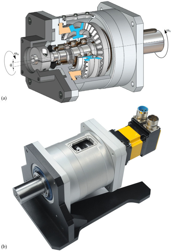
Figure 20.
Precessional transmission with gearing with straight teeth and a satellite wheel mounted on the crankshaft with concurrent axes in the precession center: 3D view (a) and experimental sample (b) of the precessional servo-gearmotor.
11.2. Precessional Transmissions with Circle Arc Teeth with the Satellite Wheel Mounted Axially Floating on the Crankshaft with Concurrent Axes in the Precession Center
The 2K–H precessional transmission shown in Figure 21 has the transmission ratio i = −164 also achieved in gearing with teeth in circle arcs with parameters θ=3.5°, βm = 35°, Z1 = 40, Z2 = 41, δ(1–2) = 15°, β(2) = 3.2°, Z3 = 33, Z4 = 32, δ(3–4) = 15°, β(3) = 3.5°, Rm = 40 mm, and Rc = 40 mm.
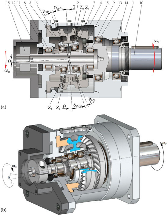
Figure 21.
2K–H (i = −164) precessional transmission with gearing with circle arc toothing and satellite wheel mounted axially floating on the crankshaft with concurrent axes in the precession center under nutation angle θ: general drawing (a) and 3D overview (b).
Driving shaft 5 with a crank function is provided with a portion inclined under the nutation angle θ in relation to the axis of axial bearings 8 and 9. On the inclined portion of driving shaft 5, satellite wheel 2 is mounted in radial–axial bearings 6 and 7. The axes of bearing pairs 8 and 9 and 6 and 7 are concurrent in precession center O.
Thus, when rotating crankshaft 5, satellite wheel 2 installed in the radial–axial bearings 6 and 7 performs spherospatial motion around the precession center O with the nutation angle θ and floats axially between immobile central wheel 3 and mobile central wheel 4. The axial positioning rates of immobile central wheel 3 and mobile central wheel 4 are restricted by deviation fields so that the point of intersection of the axes of the pairs of bearings 6 and 7 and 8 and 9 is merged with the precession center.
The coincidence of the intersection point of the axes of the pairs of bearings 6 and 7 and 8 and 9 with the precession center leads to the displacement of the center of mass of the components of the precessional node in relation to the precession center and implicitly to the dynamic imbalance with additional stresses of bearings and crankshafts, defined by Euler’s dynamic equations. The non-coincidence of the intersection point of the crankshaft axes with the precession center can lead to the displacement of the contact spot between the flanks outside of the active length of the multiple pairs of conjugated teeth.
Another peculiarity of the transmission is the constructive configuration of the casing consisting of bodies 1 and 11 with housings for the bearings and cover 12 for the assembly of the electric motor.
This casing configuration is more technological in manufacturing, including the modular assembly and disassembly of components with an adjustment of clearance or constraint in gearing according to the provisions of the design specifications.
Figure 22a shows the fabricated sample of the 2K–H (i = −164) precessional transmission with gearings with circle arc toothings and a satellite wheel mounted by axially floating on the crankshaft with concurrent axes in the precession center.
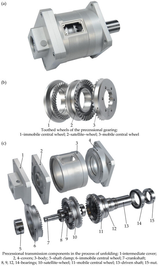
Figure 22.
A 2K–H low-power precessional transmission (i = −164) with gearing with circle arc toothing and satellite wheel mounted by axially floating on the crankshaft with concurrent axes in the precession center (a); samples of the central wheels and the satellite wheel (b) with curvilinear teeth, made of steel 4140 on CNC machine tools; and transmission components in the process of unfolding (c).
Figure 22b show samples of central wheels (1), (3) and a satellite wheel (2) fabricated from 4140 steel on numerically controlled multi-axis machine tools in cooperation with Gleason Corporation, Rochester, NY, USA, and Figure 22c shows the original components of the 2K–H precessional transmission with gearings with the transmission ratio i = −164 in the process of unfolding.
12. Conclusions and Recommendations
- To reduce the relative sliding Vsl in contact, the shape of the teeth is changed by shortening their height by cutting the tips so that we retain in the convex–concave contact only a sufficient number of pairs of teeth. This was determined using the contact pressure resistance calculation σH of the teeth at points k0–k3 or k1–k3 (k4).
- The toothed precessional gear AD with the correlation Z1 = Z2 − 1 and Z4 = Z3 − 1 and an angle of the conical axoid δ > 0° is recommended in precessional transmissions with a reducer operation regime due to the geometry of the convex–concave contact with a small difference in the radii of curvature and the low relative sliding velocity with friction between the conjugated flanks.
- The precessional gear AD with the correlation Z4 = Z3 + 1 (or Z1 = Z2 + 1), an angle of the conical axoid δ ≥ 0°, and a profile angle of the teeth of the central wheel higher than αw > 45° is recommended in transmissions with a multiplier operation regime due to the kinetostatics being favorable to transforming the rotational motion of the central wheel into spherospatial motion of the satellite wheel with the frequency of precession cycles ns = Z4.
- In precessional transmissions with spherospatial motion with a fixed point, the functional characteristics can be increased in two ways, namely:
- Based on the use of gears with several pairs of teeth simultaneously in gearing;
- Based on the use of gearings with convex–concave tooth flank contact geometries with a small difference in flank curvatures.
- The dependence of the relative sliding in convex–concave contacts of the teeth and the rolling of profiles around the contact points were analyzed depending on the precession angle ψ and the angular speed of the crankshaft.
- Different technical solutions were recommended to realize the mechanisms for transforming the crankshaft’s rotary movement into the satellite wheel’s spherospatial movement, which ensures the teeths’ spherospatial interaction and reduces the rotational movement.
- Technical solutions were recommended regarding the realization of technologies for generating convex–concave flank profiles, which ensure the multiplicity of teeth meshing, in accordance with the principles of the fundamental law of engagement.
13. Patents
The profile of the central gear teeth is variable, with a continuously increasing curvature from the tooth root to the tip. The shape of the variable profile of the teeth of the stationary and movable center wheels as a function of the configuration parameters [Zg − θ, ±1] is protected by US and German Patents [34,35].
Author Contributions
Conceptualization, I.B.; methodology, I.B. and V.B.; software, M.V.; validation, I.B., V.B. and M.V.; formal analysis, I.B. and M.V.; investigation, I.B., V.B. and M.V.; resources, I.B. and V.B.; data curation, M.V.; writing—original draft preparation, I.B.; writing—review and editing, I.B. and M.V.; visualization, M.V.; supervision, I.B. and V.B.; project administration, I.B.; funding acquisition, V.B.. All authors have read and agreed to the published version of the manuscript.
Funding
This research was funded by [TsN PO “Kometa”, Moscow, 1988] grant number [GR 01840010860]; [VNIPI Okeanmash, Moscow, 1988] grant number [GR 01860008724]; [VNIPI Okeanmash, Moscow, 1989] grant number [GR 01890001654]; [Technical University of Moldova, Chisinau, 1990] grant number [01900002471]; [Technical University of Moldova, Chisinau, 1992] grant number [01880047848]; [Technical University of Moldova, Chisinau, 1996] grant number [0196MD 00976]; [Technical University of Moldova, Chisinau, 2001] grant number [0101MD 01814]; [Grant CRDF, North Carolina, USA, 2002] grant number [USA MP1-2287]; [Technical University of Moldova, Chisinau, 2002] grant number [0101MD 01814]; [Technical University of Moldova, Chisinau, 2004] grant number [0104MD 02527]; [Technical University of Moldova, Chisinau, 2011] grant number [626 INST]; [Technical University of Moldova, Chisinau, 2015] grant number [676 INST]; [Technical University of Moldova, Chisinau, 2020] grant number [20.80009.5007.24]. The APC was funded by [Technical University of Moldova].
Data Availability Statement
Data is contained within the article.
Conflicts of Interest
The authors declare no conflict of interest.
Notation
| PT | Precessional transmission |
| 2K–H | Precessional planetary transmission with two central wheels (2K) and a crankshaft (H) |
| Precessional gear with bolts | |
| Precessional gear with straight teeth | |
| Precessional gear with circle arc teeth | |
| Precessional gearing with bolts with convex–concave contact | |
| Precessional toothed gearing with convex–convex contact | |
| Precessional toothed gearing with convex–concave contact | |
| Precessional toothed gearing with convex–concave contact of circle arc teeth | |
| The general parametric configuration of the precessional gear on which the geometry of the tooth flank profiles and the kinematics of their point of contact depend, namely: the number of teeth of the conjugate wheels Z1(4), Z2(3) and their co-relation Z1(4) = Z2(3) ± 1; the angle of nutation of the spherospatial motion θ[deg]; the angle of the bevel gear axoid and the angle of taper of the satellite wheel teeth | |
| The parametric configuration of the precessional gear with the correlation of the numbers of teeth of the conjugated wheels and the reducer operating mode | |
| The parametric configuration of the precessional gear with the correlation and multiplier operating mode (of a reducer in the case of ) | |
| The generation of tooth flanks via spatial tumbling–rolling with a cone trunk tool shape | |
| The generation of tooth flanks via spatial tumbling–rolling with a “peripherally profiled disk-shaped” tool shape | |
| The generation of straight teeth with cylindrical tools using multi-axis CNC machine tools | |
| 2K–H, 4K–2H, 6K–3H | Kinematic structures with two, four, and six central wheels, respectively |
| Convex–concave contact of straight teeth | |
| Convex–concave contact of circle arc teeth | |
| ψ | The positioning angle of the crankshaft (of precession) [deg] |
| φ | The rotation angle of the satellite around its own axis [deg] |
| The linear velocity of the contact point E1 on the tooth profile of the central wheel [m/s] | |
| The linear velocity of the contact point E2 on the tooth profile of the satellite wheel [m/s] | |
| The relative sliding in the contacts of the tooth flank profiles [m/s] | |
| The relative rolling in the contacts of the tooth flank profiles [1/s] | |
| The tool’s angular speed [1/s] |
References
- Braren, L.K. Gear Transmission. U.S. Patent 1,694,031, 12 July 1932. [Google Scholar]
- Shannikov, V.M. Planetary Gearboxes with Off-Pole Engagement; Mashgiz: Moscow, Russia, 1948; 320p. (In Russian) [Google Scholar]
- Sensinger, I.W. Unified approach to cycloid drive profile, stress and efficiency optimization. J. Mech. Des. 2010, 132, 024503. [Google Scholar] [CrossRef]
- Lobastov, V.K. On the Distribution of Forces in the Pin Gearing of a Planetary-Pin Reduction Gearbox. Mashinostroenie 1970, 7, 24–28. (In Russian) [Google Scholar]
- Vorobyov, Y.V. Analytical Basis for Assessing the Durability of Work Surfaces in Rolling with Slippage. Mashinovedenie 1984, 4, 67–76. (In Russian) [Google Scholar]
- Dion, J.L.; Pawelski, Z.; Chianca, V.; Zdziennicki, Z.; Peyret, N.; Uszpolewicz, G.; Ormezowski, J.; Mitukiewicz, G.; Lelasseux, X. Theoretical and Experimental Study for an Improved Cycloid Drive Model. J. Appl. Mech. 2020, 87, 011002. [Google Scholar] [CrossRef]
- Musser, C.W. Strain Wave Gearing. U.S. Patent 2,906,143, 29 September 1959. [Google Scholar]
- Ivanov, M.N.; Shuvalov, S.A.; Finogenov, V.A. Experimental Determination of the Number of Simultaneously Engaging Teeth and the Values of Their Deformation in Wave Transmissions. Mashinostroenie 1968, 9, 37–40. (In Russian) [Google Scholar]
- Radford, N.A.; Strawser, P.; Hambuchen, K.; Mehling, J.S.; Verdeyen, W.K.; Donnan, A.S.; Holley, J.; Sanchez, J.; Nguyen, V.; Bridgwater, L.; et al. Valkyrie: NASA’s first bipedal humanoid robot. J. Field Robot. 2015, 32, 397–419. [Google Scholar] [CrossRef]
- Preissner, C.A. High- Fidelity Harmonic Drive Model: Experiment, Simulation and Application. Ph.D. Thesis, University of Illinois at Chicago, Chicago, IL, USA, 2009. [Google Scholar]
- Ginsburg, E.G. Harmonic Gear Drives. AD-783578; Foreign Technology Division Wright-Patterson Air Force Base: Dayton, OH, USA, 1974. [Google Scholar]
- Wildhaber, E. Helical Gearing. U.S. Patent 1,601,750, 5 October 1926. [Google Scholar]
- Wildhaber, E. Gear Tooth Shape. U.S. Patent 3,251,236, 17 May 1966. [Google Scholar]
- Dyson, A.; Evans, H.P.; Snidle, R.W. Wildhaber-Novicov circular arc gear: Some properties of relevance to their design. Proc. R. Soc. Lond. A Math. Phys. Sci. 1989, 425, 341–363. [Google Scholar]
- Stadtfeld, H.I. Gleason Bevel Gear Technology—The Sciences of Gear Engineering and Modern Manufacturing Methods for Angular Transmisiions; Gleason Publication: New York, NY, USA, 2014. [Google Scholar]
- Dowson, D.; Higginson, G.R. Elasto-Hydrodynamic Lubrication, SI ed.; Pergamon Press: Oxford, UK, 1977. [Google Scholar]
- Radzevich, S.P. An Examination of High-Conformal Gearing; Gear Solutions: Pelham, AL, USA, 2018; pp. 31–39. [Google Scholar]
- GOST 15023-76; Novikov Gears Are Cylindrical with Two Lines of Engagement. Russian Technical Standard: Moscow, Russia, 1977. (In Russian)
- GOST 30224-96; Novikov Cylindrical Gear Transmissions with Tooth Surface Hardness of at Least 35 HRCe. Russian Technical Standard: Moscow, Russia, 2000. (In Russian)
- Novicov, M.L. Gears and Cam Mechanisms with Point Engagement System. Patent SU 109113 A1, 19 April 1956. (In Russian). [Google Scholar]
- Colbourne, J.R. The contact stress in Novikov gears. Mech. Mach. Theory 1989, 24, 223–229. [Google Scholar] [CrossRef]
- Kedrowski, K.; Slimak, P. Wobbling Gear Drivetrain for Cordless Screwdriver Honors Theses; Western Michigan University: Kalamazoo, MI, USA, 1993. [Google Scholar]
- Lemanski, A.; Monahan, T.J. Non-Traction Pericyclic CVTs; SAE International: Warrendale, PA, USA, 2004; Volume 40, p. 5. [Google Scholar]
- Nelson, C.A.; Cipra, R. Similarity and equivalence of nutating mechanisms to bevel epicyclic gear trains for modeling and analysis. J. Mech. Des. 2005, 127, 269–277. [Google Scholar] [CrossRef]
- Jasem, M.A.; Krauinsh, P.Y. Kinematical analysis of the nutation speed reducer. IOP Conf. Ser. Mater. Sci. Eng. 2019, 510, 7. [Google Scholar] [CrossRef]
- Jasem, M.A.; Krauinsh, P.Y. Features of the Engagement of the Nutation Speed Reducer. J. Adv. Electr. Devices MAT J. 2019, 4, 27–32. [Google Scholar]
- Gracia, P.L.; Crispel, S.; Saerens, E.; Cerstraen, T.; Lefeber, D. Compact Gearboxes for Modern Robotics A Review. Front. Robot. AI 2020, 7, 103. [Google Scholar]
- Barbagelata, A.; Ellero, S.; Lando, R. Planetary Gearbox. European Patent No. EP2975296A3, 31 August 2016. [Google Scholar]
- Barbagelata, A.; Corsini, R. Riduttore Ad Ingranaggi Conici Basculanti. Italian Patent No. IT SV20000049A1, 19 October 2000. [Google Scholar]
- Bostan, I.A. Precessional Transmissions with Multiple Pair Gear; Stiinta: Chisinau, Moldova, 1991; 356p. (In Russian) [Google Scholar]
- Bostan, V. Mathematical Models in Engineering; Bons Offices: Chişinău, Moldova, 2014; 470p, ISBN 978-9975-80-831-6. (In Romanian) [Google Scholar]
- Bostan, I.; Babaian, I. Manufacturing Procedure of the Modified Teeth of Precessional Gears. Patent S.U. 1663857 A1, 5 January 1988. (In Russian). [Google Scholar]
- Bostan, V.; Bostan, I.; Vaculenco, M. Precessional Gear Transmissions. Patent WO/2021/137682, 8 July 2021. [Google Scholar]
- Bostan, I.; Bostan, V.; Vaculenco, M. Deutsches Patent-und Markenamt; Zahnradubertragung Mit Prazessions Bewegung. Deutsches Patent DE 212020000799 U1, 3 November 2022. [Google Scholar]
- Bostan, V.; Bostan, I.; Vaculenco, M. Precessional Gear Transmission. U.S. Patent 11,913,523 B2, 27 February 2024. [Google Scholar]
- Bostan, I. Planetary Precessional Transmissions: Synthesis and Generation Technoloies. In Power Transmissions, Proceedings of the 4th International Conference, Sinaia, Romania, 20–30 June 2012; Springer: Berlin/Heidelberg, Germany, 2012; pp. 21–42. [Google Scholar]
- Bostan, I.A. Creation of Planetary-Precessional Gears with Multi-Pair Gearing. Ph.D. Thesis, Bauman Moscow State Technical University, Moscow, Russia, 1989. Volume 1, 511p, Volume 2 (App.), 236p (In Russian). [Google Scholar]
- Bostan, I.A. Precessional Gear Transmission. Patent SU 1455094 A1, 30 January 1989. (In Russian). [Google Scholar]
- Gromyko, P.N.; Zholobov, A.A.; Statsenko, A.A.; Khatetovskiy, S.N.; Puskov, O.M. Planetary Presession Transmissions. Kinematic, Power and Technological Aspects of Their Creation; Belarusian State Polytechnical Academy: Minsk, Belarus, 2000; 252p. (In Russian) [Google Scholar]
- Skoybeda, A.T. Kinematic-Cylindrical Precessional Gearboxes; Belarusian State Polytechnical Academy: Minsk, Belarus, 2001; 199p. (In Russian) [Google Scholar]
- Skoybeda, A.T.; Gromyko, P.N.; Khatetovskiy, S.N. Regarding to the Problem of Shaping the Gear Tooth Profile of Planetary Precession Gear Wheels; NASB: Minsk, Belarus, 2001; pp. 69–73. (In Russian) [Google Scholar]
- Tronin, I. The wonderful world of reduction gears created by Ion Bostan. Partn. J. 1991, 5, 20+46. [Google Scholar]
- Bostan, I.; Mazuru, S.; Scaticailov, S. Precessional Gear Tooth Machining Procedure. Patent MD 2120 C2, 31 March 2003. [Google Scholar]
- Bostan, I.; Mazuru, S.; Olevschi, A. Precessional Gear Tooth Machining Procedure. MD 3532 C2, 31 March 2008. [Google Scholar]
Disclaimer/Publisher’s Note: The statements, opinions and data contained in all publications are solely those of the individual author(s) and contributor(s) and not of MDPI and/or the editor(s). MDPI and/or the editor(s) disclaim responsibility for any injury to people or property resulting from any ideas, methods, instructions or products referred to in the content. |
© 2024 by the authors. Licensee MDPI, Basel, Switzerland. This article is an open access article distributed under the terms and conditions of the Creative Commons Attribution (CC BY) license (https://creativecommons.org/licenses/by/4.0/).