Abstract
Equipment integrity is an essential aspect of process engineering. Design guidelines facilitate the design and production of safe-to-operate and economic devices. Thin-walled, slit-shaped modules form a subgroup of process engineering devices made via additive manufacturing (AM). Being subject to internal pressure, they have lacked design guidelines until now. We derived a user-centered calculation model for such modules with regular internal structures. It was validated with Finite Element Analysis (FEA) and practical pressure tests for which the modules were manufactured additively. The performance of the calculation could be confirmed, and a design graph was derived. Slit-shaped modules with appropriate internal structures can withstand high pressure at a minimum wall thickness, and they are efficiently fabricated. These structures, being pins, fins, lattice, or heat transfer enhancing fluid-guiding elements (FGEs), occupied approximately 10% of the modules’ internal volume.
1. Introduction
Process engineering requires devices containing hazardous materials at a high pressure and temperature. Processes like chemical reactions, adsorption, and heat transfer are often carried out at a high pressure [1]. In Fischer-Tropsch synthesis (FTS), being one example out of many, the product yield was increased using a high pressure of typically 20 to 30 [2], while reactants were flammable and toxic [3]. Thus, stability is a very important factor in safe operation.
Slit-shaped devices made with conventional manufacturing are common in micro-process engineering [4,5]. A metal additive manufacturing (AM) reactor consisting of slit-shaped modules was used successfully to carry out challenging FTS [6]. Utilizing function integration and design freedom, the AM reactor required fewer sealing surfaces and assembly steps compared to a conventional micro-reactor for FTS [7,8].
Slits can be extended in width and length, and they can be stacked to increase their capacity without a significant performance loss, making them important for engineers and researchers in the disciplines of chemical engineering and flow chemistry. Therefore, we investigated these particular modules in terms of mechanical integrity.
Finite element analysis (FEA) is one option to determine stability and optimize the part weight of almost arbitrary parts [9]. However, it requires the re-meshing of every design and computational effort. FEA interpretation depends on the designer, especially in the presence of singularities in the analysis [10].
For fast equipment development, a reliable and user-friendly calculation model for design with regard to stability is imperative. Such a model being accessible to the above-mentioned target group, who are usually not mechanical engineers, is beneficial. A model that could be handled by non-mechanical engineers and directly applied to typical slit modules encountered in micro-structured devices was not found in the literature.
For comparatively simple geometries, rectangle and circular disc formulas for stability calculation were found in a standard reference book [11]. A subset of slit-shaped modules investigated in this article can be abstracted to simple geometries and assessed using the aforementioned formulas.
The aim of this article was to perform this abstraction and validate it with FEA and experimental data. Comparing the experiment, formulas, and simulations of failure in AM parts helps expand knowledge and increase trust in this promising manufacturing method [12].
2. Materials and Methods
The investigated modules consisted of parallel planar walls forming a narrow slit with fluidic connectors at the bottom and top ends. For its material, stainless steel 316L was chosen due to its strength, corrosion resistance, and prevalence [13,14]. For the composition, refer to Table S1. The pressure at which a module is operated could be above the outside pressure, the outside being the surroundings or another module operated at a lower pressure. Planar walls tend to buckle when subjected to a pressure difference across the two sides. Under otherwise constant conditions, buckling is more likely when the smaller of the rectangular side’s length increases or the wall thickness decreases [11]. Excess wall thickness must be avoided, but with every increase in the device’s size, the walls become larger.
The following approaches were pursued to enhance mechanical stability: 1. the deformation of the walls in the direction of the y-axis and 2. the insertion of internal structures (Figure 1).
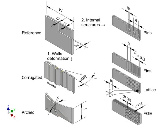
Figure 1.
Designs for mechanical stability testing.
Walls bent in three-dimensional (3D) space are expected to be more stable than planar ones [15]. Evenly distributed structures connecting neighboring walls, preventing buckling, were introduced into the design, the structures being hexagonally arranged pins, evenly distributed fins, lattice, or fluid guiding elements (FGE). Topology optimization was not used, mainly due to two reasons. The first reason was that process engineering devices cannot be designed only by optimizing the mechanical load and weight. The flow pattern and accessibility of the catalyst and sensors are crucial. The second reason was that the chemical industry has strong regulatory requirements, especially for pressure vessels. Validation is facilitated using well-known features such as regular pins instead of topology-optimized shapes.
Internal structures have possible downsides: a reduction in the fluidic volume and the addition of material to the design. The volume of the internal structure per slit volume is called the volume fraction , and it was kept as low as possible. Nevertheless, there is a physical minimum for the volume fraction of internal structures. Based on a force equilibrium (Equation (1)), internal structures are expected to rupture below a certain volume fraction. This resulted in = 0.008 for p = 30 , a margin of error of , and a yield strength of = 582 taken from [16] for vertical tensile samples.
Internal structures have been identified by other persons as well as means to increase the stability of pressure vessels by adding a minimum mass [17,18,19]. The internal structures proposed in this article are unlikely to change the flow pattern significantly, as the flow is usually strongly laminar [20] in micro-structured devices.
Possible tubular portions are only minor and might occur close to fluid connections. They can be designed to protect against rupture according to well-established formulas, and they are not in the scope of this article [21].
2.1. Design and Fabrication
The empty planar module served as a reference and starting point for the design (Figure 1, top left).
2.1.1. Empty Modules
The first approach was bending the slit walls in 3D space. The entire volume between the corrugated or arched walls was available for fluid ( = 0). The deformation was effected in a way that still permitted multiple modules to be stacked seamlessly. The wall thickness of these samples was = 1 mm.
Three of the modules comprised corrugated walls. Corrugated-5 and Corrugated-10 had five and ten corrugations parallel to the z-axis, respectively. Corrugated-7’ had seven corrugations parallel to the x-axis. The angle between the corrugation and the -plane was always = 20 .
Arched-5, -15, -30, and Arched-45 were four modules with walls warped over the -plane. The digits denote the cutting angle between the wall and the -plane .
2.1.2. Modules with Internal Structures
Four categories of internal structures were used inside narrow planar slits in this work: pins, fins, lattice, and FGE [22].
Connecting both sides of the slit directly, pins were characterized by their shape and arrangement. The cross-section of pins was a square with side length , which was the characteristic parameter. To prevent horizontal overhangs, small angles were added at both slit walls. Pins were arranged in a hexagonal manner with spacing a.
To study mechanical stability, the size and spacing of internal pins varied over a wide range. The side length of quadratic pins was = 0.26 mm–5 mm, while the spacing was a = 1 mm–20 mm. The wall thickness was = mm. The width and length were w = 40 mm and l = 60 mm, respectively.
The volume fraction was calculated from geometrical considerations, it and took values of = 0.01–0.19.
Fins connected both sides of the slit directly and separated the slit into parallel channels. The thickness of fins was = = const. The characteristic parameter was the distance between two fins = 1 mm–4 mm. Fillets were added where the fins transitioned into the walls. Again, the volume fraction was calculated from geometrical considerations, and it took values of = 0.1–0.33.
The lattice was of a body-centered cubic type with a side length of = 1 mm. Unlike the other internal structures, this one was not derived from CAD but from the printer’s software. Under the scan strategy used, the strut diameter was = mm as measured with a caliper. From this, a volume fraction of = 0.186 was calculated.
The geometry of a planar FGE, consisting of one fluid guiding unit (FGU) repeated with certain distances in three dimensions, can be varied in multiple ways. However, the following simplifications were made: the ratio of the depth, width, and length of an FGU was fixed to 1:2:4 (Figure 2, top), and distances between repeating units were minimal, e.g., spacing of = (Figure 2, bottom).
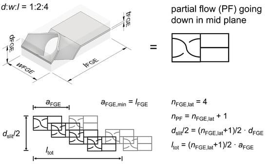
Figure 2.
Definitions concerning FGE.
In the case of FGE, assessing the volume fraction was not straightforward. An explicit formula for , based on and the wall thickness , was established and checked with fabricated samples (Equation (2)).
The numerator of Equation (2) was obtained with the help of computer aided design (CAD). Knowing it is an ideal, the thickness in CAD was set to = mm. The mass of the fabricated FGE samples was assessed, and the wall thickness was measured as 0.3 mm–0.4 mm. Based on this, could be calculated. The results from the explicit formula, as well as the experiments, are shown in Table 1. Especially at low values of , the was much higher than expected, suggesting that this wall thickness was much higher than in CAD. This is probably due to the strong curvature of a small FGE.

Table 1.
Calculated and measured values of .
FGE-equipped modules for stability testing had design parameters of = 1.333 and 4 mm. They could only be manufactured with = mm. At the interface of the FGE and the wall, the spacing equaled in the range of 5.33 mm–16 mm.
2.1.3. Connections and Fabrication
Internal threads enabled the slits to be attached to standard externally threaded connectors. The internal G1/8″-thread was designed individually according to [23] with higher diameter values to compensate for tolerances. It had clamping surfaces on the outside, and cones transitioned the rectangular cross-section of the slit into the circular cross-section of the thread section, resulting in a high wall thickness for these sections; = 1 mm–2 mm (Figure 3a). The cones, which were not in the scope of the study, allowed for little overhangs, a flow-through with a smooth cross-section transition, and good depowdering [24].
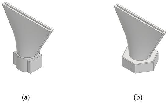
Figure 3.
CAD representation of module connectors. (a) Additive threaded connection: G1/8″. (b) Hybrid threaded connection: G1/8″ (possible at bottom end only).
The internal thread section at the lower end could be omitted when the part was manufactured on a nut that had been positioned inside the printer beforehand (Figure 3b). This approach combining conventional nuts and PBF-LB/M additive manufacturing is called hybrid manufacturing, and it and it greatly facilitated the production of modules for pressure testing [25].
The conventional substrate was 19 mm stainless steel nuts with a G1/8″ thread from Schrauben-Jäger AG (Karlsruhe, Germany, art.-n. 103806). The nuts were positioned with the help of parallel rests and fixed to the build plate with Loctite superglue by Henkel AG (Düsseldorf, Germany). Figure 4 depicts the manufacturing approach with an exemplary module. All modules tested are depicted in Supplementary Information (SI) Tables S2–S6.
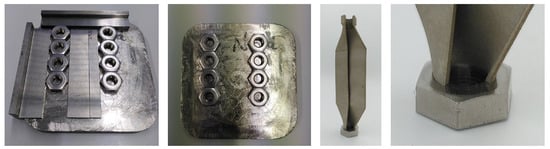
Figure 4.
Hybrid manufacturing of modules on nuts with an exemplary empty module (three-quarter cut).
The standard tessellation language (STL) files obtained from the CAD software Inventor 2022 by Autodesk (San Rafael, CA, USA) were repaired in Autodesk® Netfabb® (NF). This was necessary since, under the unrevised version, the locally very complex designs (FGE) resulted in slicing errors in the pre-process software.
Modules were printed on a Realizer SLM125 (now LASERTEC SLM12) using DMG MORI (Bielefeld, Germany). The powders used, stainless steel 316L, were supplied by Carpenter Additive (Philadelphia, PA, USA) and SLM Solutions (Lübeck, Germany). After printing, the threads at the ends were tapped and countersunk. The end surfaces were milled with a plain cutter on a Deckel (today DMG MORI) FP5 numerically controlled (NC) mill.
2.2. Experimental Method
The procedure described and shown in Figure 5 was applied to a clean and leak-tight part in order to determine the mechanical stability. The metallic modules were connected to a pressure test rig by Konstandin und Partner engineering GmbH (Pfinztal, Germany) with threaded connectors and metal-bonded polymer gaskets. The test pressure calculated with (Ref. [26]) was rounded to = 30 . The external micrometer used had a measuring tip with d = 5 mm. For modules with non-planar walls, parallel rests were employed.
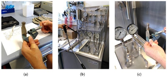
Figure 5.
Experimental procedure to test the mechanical stability. (a) Place marking in the middle of a module wall, measure the outside depth D0, and attach to the test port of the pressure test rig. (b) Fill with water via a manual pump, close the opposite connector, and increase the pressure to . (c) After a minimum Time t = 15 , measure the outside depth, , before decreasing to the ambient pressure.
2.3. Calculation Method
For modules equipped with pins, case 2j from Ref. [11] Table 11.2 (p. 457) was used in theoretical calculations. This case concerned an annular disc, fixed in the middle with guided outer edges, that was subject to a uniform load. The hexagonally arranged pins were abstracted to the annular disk in said reference as follows: The radius of the circle area equivalent to one quadratic pin was the inner radius in the reference. The radius of the circle area equivalent to one hexagonal repetition unit was the outer radius in the reference. The pressure was equal to the load per unit area q. The vertical deflection of the plate at the outer radius was the most important: it was assumed as the deflection between pins with spacing a.
For empty modules and those equipped with fins, case 6a from Ref. [11] Table 11.4 (p. 506) was used in theoretical calculations. The formulas were evaluated with the help of Microsoft Excel (Redmond, WA, USA) and Matlab R2022b by Mathworks Inc. (Nattick, MA, USA).
Material properties can be found in Table 2. These properties, being standard values for wrought 316L from Ref. [27], have been used and confirmed by several authors for additive 316L [16,28].
Table 2.
Material properties of 316L at room temperature used in calculation and simulation [27].
2.4. Simulation Method
For FEA, software ANSYS 2020 R2 Workbench and Mechanical by ANSYS Inc. (Canonsburg, PA, USA) were used. A custom material with the properties found in Table 2 was used. Only repetition units of the modules were subjected to FEA, also utilizing symmetries. The element size was mm if not otherwise mentioned.
Mechanical strength was considered sufficient when the displacement was below mm or mm when referring to a module with external depth D. This quantity is accessible with all three investigation methods, while stress was not accessible for the experimental method chosen. The maximum value was chosen to limit the deformation of a slit with d = 1 mm to 2%, which is especially important to avoid crushing the catalyst particles present.
3. Results and Discussion
Almost all modules without internal structures ( = 0) showed poor mechanical stability in experiments, the displacement being y = 0.2 mm–10 mm. The exception was the empty slit with highly arched walls Arched-45, which showed D below measuring accuracy (Figure 6).
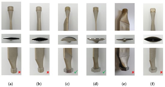
Figure 6.
Modules after pressure test. (a–c) = 1 mm. (d–f) = mm. Green check marks indicate passing; red x marks indicate failing. (a) Empty planar. (b) Corrugated-10. (c) Arced-45. (d) Pins: = 3 mm a = 9. (e) Pins: = 4 mm a = 20 mm. (f) Pins: = mm a = 5 mm.
Some pin-equipped modules showed a mode of failure referred to as “Telegraphing” in the experiments. This is known for fiber-reinforced composite materials [29]. When the distance between pins was too high mm, the walls curved outside between pins (red open circles in Figure 7). Below a certain volume fraction, , a rupture of the pins occurred, and the structure bent outside as a whole (red open square). Apart from that, most modules with pins showed excellent mechanical stability in the investigated region of = 0.02–0.19 and = 0.26 mm–5 mm (green full circles). Calculations predicted stable designs to be in the green area below the solid line in Figure 7, which concurs with experimental observations.
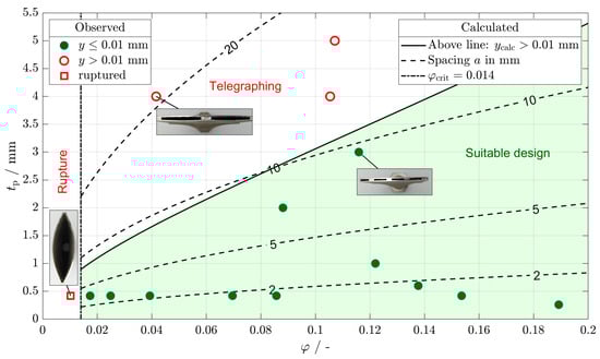
Figure 7.
Results of mechanical stability calculation and experiment.
Modules with internal fins, lattice, and FGE all passed the pressure test.
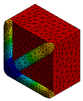
In Figure 8, for one module experiment, the calculation and simulation are compared. The module with = 4 mm and a = 20 mm deformed notably. The measured displacement of one side was = mm, while the calculated and simulated displacement had been = 0.235 and mm, respectively. Both the calculation and the simulation overestimated the experimental displacement a little and reflected the characteristic shape well.
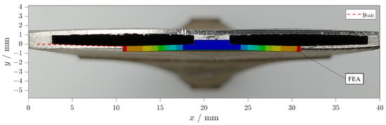
Figure 8.
Failed pin-equipped module = 4 mm a = 20 mm: photography of cross-cut in background, calculated deformation (dotted red line), and simulated deformation (multicolored area). Maximum deformation is visible at mm.
The results from the simulation, experiment, and calculation concurred. Table 3 shows the results of FEA of rectangular units. Full-size images can be found in the SI (Figures S1–S3). Mesh size independence was confirmed for each simulation. The mesh size was reduced until the maximum deformation did not change anymore ( mm for most cases). An example is provided in Figure S5. For a low width of up to 4 mm, displacement was not significant. This confirmed not only the experimental results of fin-equipped modules but also the fact that the modules did not fail at their narrow sides. Rectangular walls with w = 40 mm and = 1 mm were displaced severely in the experiment, calculation, and simulation. Displacement was only limited below the accepted value at = 5 mm.
Table 3.
Results concerning the stability of empty and fin-equipped modules: l = 60 mm.
In Table 4, pin-equipped modules are shown. Abstracting the hexagonally arranged quadratic pins led to an insignificant change in FEA displacement. The calculation and experiment yielded slightly higher values for displacement (first two columns). While the calculated and simulated deformation correctly predicted that there was no telegraphing in the module in column three, the volume fraction was close to its critical value. The simulation predicted that the stress inside the pin reached almost yield strength. Both the volume fraction and the simulation result explain the rupture of the pin-equipped module with = 0.01 (third column). All three methods agreed in revealing that a module, as shown in column four, did not deform significantly.
Table 4.
Results concerning the stability of pin-equipped modules. = mm.
Table 5 features modules for which no calculation method was available. FEA and experiments were in agreement that no significant deformation occurred for the investigated modules with an FGE and lattice.
Table 5.
Results for stability of FGE-equipped ( = mm, = mm) and lattice-equipped ( = mm) modules.
A combination of calculation and checking the volume fraction against its critical value was effective for the stability assessment. Having implemented the formula in a programmable script, it was possible to extract information on failure criteria based on all design parameters. In Figure 9, the design parameter wall thickness varied, while the load was constant, q = 3 , referring to an operation pressure of p = 20 and a safety factor of S = 1.5.
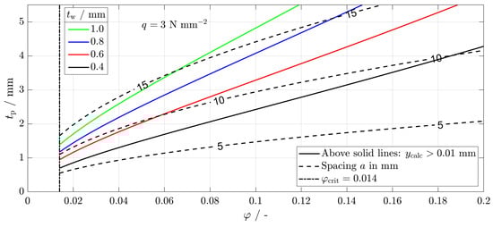
Figure 9.
Calculated stability criterion for various thicknesses at constant load.
When assuming that a design with = 0.1 is desired, the pin size can be determined by starting on the abscissa and moving upward until the solid line referring to the aimed-for wall thickness is reached. The pin size must not exceed the respective value on the ordinate. The selected pin size defines the spacing. At = mm, a pin size of = 2 mm is selected, leading to a spacing of a = mm.
Another design graph where the wall thickness is kept constant, while the load is varied, can be found in the SI (Figure S4).
The hybrid manufacturing connection was never a source of failure in our experience, which is consistent with the findings of [25].
4. Conclusions and Outlook
The wall thicknesses of several millimeters necessary for slit modules at a reasonable size without internal structures to withstand p = 30 at room temperature are unacceptable.
The first approach (deformation of the walls) was not successful in increasing the mechanical stability of planar slits. Neither corrugated nor arched walls could, except for one instance with a comparatively high thickness, withstand the pressure difference occurring at p = 30 at room temperature.
Significant insights into the stability of micro-structured devices were gained. The second approach of introducing regular internal structures of a minimal mass and volume led to stable modules. Evenly spaced internal structures with a sufficiently high volume fraction and sufficiently low spacing were stable; the exact values depended on the material properties, wall thickness, and load.
For external pressure, no failure is expected since the internal structures are unlikely to buckle with the highest slenderness ratio being for mm. This ensures both process safety and smooth operation without the compression of particles on the inside of devices, e.g., a catalyst.
To be on the safe side regarding a rupture, the volume fraction aimed for should be above the critical value. This is reasonable, as there is a chance of cracking formation starting from the points where internal structures meet the walls at steep angles, as well as from surface roughness [30].
The experiment, simulation, and calculation were in good agreement. The calculation is easy to use, especially when being implemented into tables in the form of a graph, as shown in this article.
Supplementary Materials
The following supporting information can be downloaded at https://www.mdpi.com/article/10.3390/designs8030041/s1: Table S1. Composition of metal powders; Table S2. Modules without internal structures; Table S3. Pin-equipped modules; Table S4. Fin-equipped modules; Table S5. FGE-equipped modules; Table S6. Lattice-equipped module; Figure S1. FEA results of empty and fin-equipped modules; Figure S2. FEA results of pin-equipped modules; Figure S3. FEA results of FGE-equipped and lattice-equipped modules; Figure S4. Calculated stability criterion for various loads at constant thickness; Figure S5. Results of mesh independence study.
Author Contributions
Conceptualization, D.F.M., C.K. and R.D.; methodology, D.F.M.; software, D.F.M.; validation, D.F.M.; formal analysis, D.F.M.; investigation, D.F.M.; resources, C.K. and R.D.; data curation, D.F.M.; writing—original draft preparation, D.F.M.; writing—review and editing, D.F.M., C.K. and R.D.; visualization, D.F.M. and C.K.; supervision, C.K. and R.D.; project administration, C.K. and R.D.; funding acquisition, R.D. All authors have read and agreed to the published version of the manuscript.
Funding
We are grateful to the German Federal Ministry of Education and Research (BMBF) for funding this work through project Kopernikus P2X-Phase 2 (Funding ID: 03SFK2K0-2).
Data Availability Statement
Data can be made available upon request.
Acknowledgments
We sincerely thank the KIT-Publication Fund of the Karlsruhe Institute of Technology Library for its support and the funding bodies of the Large Scale Data Facility (https://www.scc.kit.edu/forschung/11843.php, accessed on 5 March 2024). We appreciate the help of our colleagues Manuel Hofheinz for fabrication and Cornelia Schorle for testing.
Conflicts of Interest
The authors declare no conflict of interest.
Abbreviations
| Symbol | Meaning | Unit |
| A | Area | mm2 |
| a | Spacing | mm |
| D | Depth external | mm |
| y | displacement | mm |
| d | Depth | mm |
| d | Diameter | mm |
| l | Length | mm |
| p | Pressure | Pa |
| q | Mechanical load | MPa |
| Proof strength at 0.2 % strain | MPa | |
| t | Dimension | mm |
| t | Thickness | mm |
| t | Time | s |
| w | Width | mm |
| Deflection | mm | |
| crit | critical | |
| e | empty | |
| f | fins | |
| FGE | related to FGE | |
| l | lattice | |
| p | pins | |
| strut | strut | |
| w | wall | |
| 3D | three-dimensional | |
| AM | additive manufacturing | |
| CAD | computer aided design | |
| FEA | finite element analysis | |
| FGE | fluid guiding element | |
| FGU | fluid guiding unit | |
| FTS | Fischer-Tropsch synthesis | |
| NC | numerically controlled | |
| NF | Autodesk Netfabb | |
| SI | Supplementary Information | |
| STL | standard tessellation language |
References
- Jess, A.; Wasserscheid, P. Chemical Technology: An Integral Textbook; CourseSmart; Wiley-VCH: Weinheim, Germany, 2013. [Google Scholar]
- de Klerk, A. Fischer-Tropsch Refining, 1st ed.; Wiley-VCH: Hoboken, NJ, USA; Weinheim, Germany, 2011. [Google Scholar] [CrossRef]
- Deutsche Gesetzliche Unfallversicherung, e.V. GESTIS-Stoffdatenbank. 2023. Available online: https://gestis.dguv.de/ (accessed on 11 November 2023).
- Herz, G.; Gallwitz, M.; Näke, R.; Megel, S.; Jahn, M.; Reichelt, E. Lab-Scale Demonstration of By-Product Utilization in an Integrated Power-to-Liquid Process Applying Co-Electrolysis. Energy Technol. 2023, 11, 2201057. [Google Scholar] [CrossRef]
- Woo, Y.; Oh, D.B.; Park, J.E.; Han, S.J.; Lee, Y.J.; Park, M.J. CFD Modeling of a Multichannel Fischer–Tropsch Reactor Module with Microscale Cooling Channels: Effects of Mirrored Structure Cooling Layers. Korean J. Chem. Eng. 2023, 40, 2572–2580. [Google Scholar] [CrossRef]
- Metzger, D.F.; Klahn, C.; Dittmeyer, R. Downsizing Sustainable Aviation Fuel Production with Additive Manufacturing—An Experimental Study on a 3D Printed Reactor for Fischer-Tropsch Synthesis. Energies 2023, 16, 6798. [Google Scholar] [CrossRef]
- Almeida, L.C.; Sanz, O.; D’olhaberriague, J.; Yunes, S.; Montes, M. Microchannel Reactor for Fischer–Tropsch Synthesis: Adaptation of a Commercial Unit for Testing Microchannel Blocks. Fuel 2013, 110, 171–177. [Google Scholar] [CrossRef]
- Cao, C.; Hu, J.; Li, S.; Wilcox, W.; Wang, Y. Intensified Fischer–Tropsch Synthesis Process with Microchannel Catalytic Reactors. Catal. Today 2009, 140, 149–156. [Google Scholar] [CrossRef]
- Kroll, E.; Buchris, E. Weight Reduction of 3D-printed Cylindrical and Toroidal Pressure Vessels through Shape Modification. Procedia Manuf. 2018, 21, 133–140. [Google Scholar] [CrossRef]
- Unnikrishnan Nair, S.; Somanath, S. (Eds.) Introduction to Finite Element Analysis: A Textbook for Engineering Students; Springer: Singapore, 2024. [Google Scholar] [CrossRef]
- Young, W.C.; Budynas, R.G. Roark’s Formulas for Stress and Strain, 7th ed.; McGraw-Hill: New York, NY, USA, 2007. [Google Scholar]
- Vu, H.M.; Meiniger, S.; Ringel, B.; Hoche, H.; Oechsner, M.; Weigold, M.; Seidel, C. Investigation on Surface Characteristics of Wall Structures out of Stainless Steel 316L Manufactured by Laser Powder Bed Fusion. Prog. Addit. Manuf. 2024. [Google Scholar] [CrossRef]
- Deutsche Edelstahlwerke GmbH. Werkstoffdatenblatt X2CrNiMo17-12-2 1.4404; Technical Report; Deutsche Edelstahlwerke GmbH: Witten, Germany, 2015. [Google Scholar]
- Ashby, M.F. Materials Selection in Mechanical Design, 4th ed.; Butterworth-Heinemann: Amsterdam, The Netherlands, 2011. [Google Scholar]
- Zhuang, W.; Yang, C.; Wu, Z. Mechanical Stability of Hybrid Corrugated Sandwich Plates under Fluid-Structure-Thermal Coupling for Novel Thermal Protection Systems. Appl. Sci. 2020, 10, 2790. [Google Scholar] [CrossRef]
- Charmi, A.; Falkenberg, R.; Ávila, L.; Mohr, G.; Sommer, K.; Ulbricht, A.; Sprengel, M.; Saliwan Neumann, R.; Skrotzki, B.; Evans, A. Mechanical Anisotropy of Additively Manufactured Stainless Steel 316L: An Experimental and Numerical Study. Mater. Sci. Eng. A 2021, 799, 140154. [Google Scholar] [CrossRef]
- Meyer, J. Pressure Vessel. US20160238193A1, 18 August 2016. [Google Scholar]
- Kotilar, I.K. Pressure Vessels, Design and Method of Manufacturing Using Additive Printing. US20160061381A1, 3 March 2016. [Google Scholar]
- Kiener, C.; Boschert, S.; Küsters, Y.; Nicolai, A.; Otto, R. Hochdruck-geeignete AM-Konstruktionselemente Mit Hierarchisch-funktionalen Metallstrukturen. Chem. Ing. Tech. 2022, 94, 1040–1045. [Google Scholar] [CrossRef]
- Kockmann, N. Transport Phenomena in Micro Process Engineering; SpringerLink Bücher; Springer: Berlin/Heidelberg, Germany, 2008. [Google Scholar] [CrossRef]
- DIN EN 13445-1:2018-12; Unbefeuerte Druckbehälter—Teil1: Allgemeines. DIN e.V.: Berlin, Germany, 2018.
- Hansjosten, E.; Wenka, A.; Hensel, A.; Benzinger, W.; Klumpp, M.; Dittmeyer, R. Custom-Designed 3D-printed Metallic Fluid Guiding Elements for Enhanced Heat Transfer at Low Pressure Drop. Chem. Eng. Process.—Process Intensif. 2018, 130, 119–126. [Google Scholar] [CrossRef]
- DIN ISO 228-1; Rohrgewinde Für Nicht Im Gewinde Dichtende Verbindungen: Teil 1: Maße, Toleranzen Und Bezeichnung (ISO 228-1:2000). DIN e.V.: Berlin, Germany, 2003.
- Pei, E.; Bernard, A.; Gu, D.; Klahn, C.; Monzón, M.; Petersen, M.; Sun, T. (Eds.) Springer Handbook of Additive Manufacturing; Springer Handbooks; Springer International Publishing: Cham, Switzerland, 2023. [Google Scholar] [CrossRef]
- Ferchow, J.; Bühler, M.; Schlüssel, M.; Zumofen, L.; Klahn, C.; Hofmann, U.; Kirchheim, A.; Meboldt, M. Design and Validation of a Sheet Metal Clamping System for Additive Manufacturing and Post-Processing. Int. J. Adv. Manuf. Technol. 2022, 119, 7947–7967. [Google Scholar] [CrossRef]
- BG RCI. Druckprüfungen von Druckbehältern Und Rohrleitungen: Flüssigkeitsdruckprüfungen, Gasdruckprüfungen; BG RCI: Heidelberg, Germany, 2012. [Google Scholar]
- IMA Materialforschung und Anwendungstechnik GmbH. WIAM(R) Metallinfo. 2022. Available online: https://www.wiamonline.de/wiamdb/wiamlogin.php (accessed on 19 February 2021).
- Hitzler, L.; Hirsch, J.; Heine, B.; Merkel, M.; Hall, W.; Öchsner, A. On the Anisotropic Mechanical Properties of Selective Laser-Melted Stainless Steel. Materials 2017, 10, 1136. [Google Scholar] [CrossRef] [PubMed]
- Türk, D.A. Exploration and Validation of Integrated Lightweight Structures with AM and FRP Parts. Ph.D. Thesis, ETH Zürich, Zürich, Switzerland, 2017. [Google Scholar]
- van Hooreweder, B.; Apers, Y.; Lietaert, K.; Kruth, J.P. Improving the Fatigue Performance of Porous Metallic Biomaterials Produced by Selective Laser Melting. Acta Biomater. 2017, 47, 193–202. [Google Scholar] [CrossRef] [PubMed]


Disclaimer/Publisher’s Note: The statements, opinions and data contained in all publications are solely those of the individual author(s) and contributor(s) and not of MDPI and/or the editor(s). MDPI and/or the editor(s) disclaim responsibility for any injury to people or property resulting from any ideas, methods, instructions or products referred to in the content. |
© 2024 by the authors. Licensee MDPI, Basel, Switzerland. This article is an open access article distributed under the terms and conditions of the Creative Commons Attribution (CC BY) license (https://creativecommons.org/licenses/by/4.0/).