Article

Decoupler-Based Feedback Control Strategy for Interlinking Converter in a Hybrid Microgrid

by
Rekha P. Nair
and
Kanakasabapathy Ponnusamy
*
Department of Electrical and Electronics Engineering, Amrita Vishwa Vidyapeetham, Amritapuri, Kollam 690525, India
*
Author to whom correspondence should be addressed.
Designs 2023, 7(4), 91; https://doi.org/10.3390/designs7040091
Submission received: 18 May 2023 / Revised: 28 June 2023 / Accepted: 30 June 2023 / Published: 6 July 2023
(This article belongs to the Topic Multi-Energy Systems, 2nd Volume)

Abstract

:
In a hybrid microgrid with AC and DC subgrids, the interlinking converter (IC) is the key element connecting the two subgrids. The performance of the interlinking converter is adversely affected by the d- and q-axis impedance interaction between the inner control loops. This interaction is highly undesirable since it adversely affects both the dynamic and the steady-state performance of the IC. Based on this, a novel feedback-based decoupling strategy is developed to overcome the cross-coupling effect in the mathematical model of the interlinking converter. This is a novel concept since the feed-forward compensation techniques are utilized to address the cross-coupling effect in prior related works, which has an inherent disadvantage of additional disturbance due to the addition of the compensating terms. In this study, a complete decoupling of the d and q axes was achieved, and the first-order transfer functions were obtained for the control loops using systematic block-reduction algebra and direct synthesis approaches. With this model, computational complexities are reduced and the inner control loops are free from impedance interaction effects, thereby achieving enhanced transient stability. Perfect decoupling of the voltage vectors is achieved by the matrix diagonalization method. Furthermore, the novelty of the proposed control is that the decoupled model is integrated with a normalization-based coordinate control strategy for effective bidirectional power transfer via the interlinking converter. Additionally, the proposed controller’s validity was tested for its performance under different transients in the MATLAB Simulink platform. The simulation results validated the proposed control strategy by showing that a faster response is ensured. A high-quality reference signal is generated due to the effective decoupling achieved. This observation was also validated by comparing the T.H.D. levels of a decoupled model’s reference power signal to one without a decoupling strategy.

1. Introduction

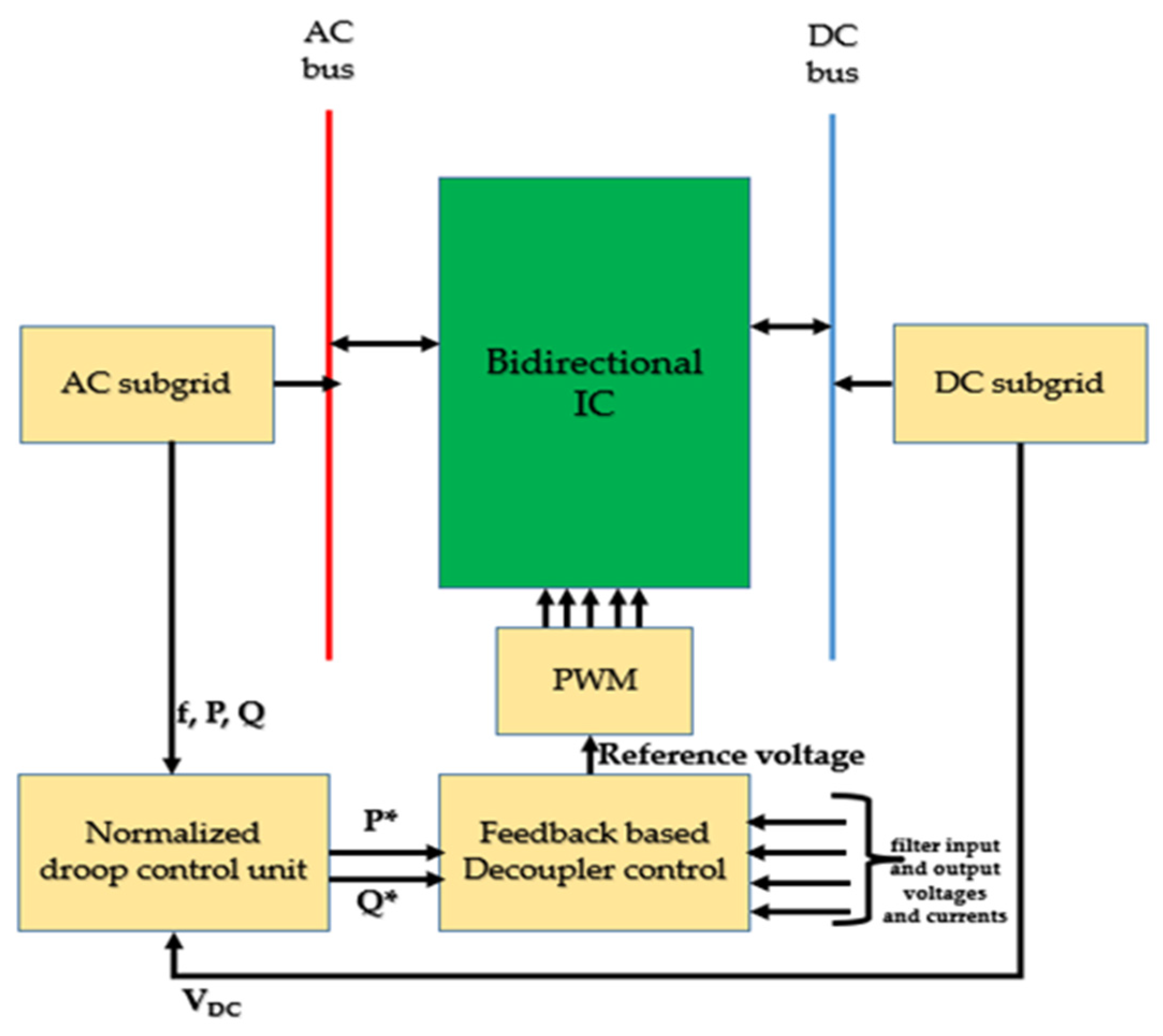
A microgrid can be considered a low- or medium-voltage localized power system with distributed energy sources, storage, and loads. Its capacity may range from several kilowatts to a few megawatts. Microgrids can be topologically classified as DC, AC, or hybrid [1,2,3]. A microgrid can operate in two modes, namely grid-connected or autonomous. Maintaining the DC bus voltage within the limits is the main challenge in a microgrid. In the case of an AC microgrid, the utility will take care of the AC bus voltage and frequency in the grid-connected mode. In an autonomous or islanded mode of operation, the microgrid needs its own control system to maintain bus voltage and frequency stability [4,5]. Additionally, a vast amount of literature is available on the autonomous operation of AC and DC microgrids. Figure 1 shows a hybrid microgrid consisting of an AC and a DC bus, which are interlinked by a bidirectional interlinking converter (IC) [6,7].
The IC controls the bidirectional power flow between the two subgrids. In doing so, it has three modes of operation [8]:
  • Mode 1—ideal mode: both subgrids are able to meet their respective demands independently.
  • Mode 2—AC to DC power transfer: the DC source is unable to meet its demand, and the additional requirement will be transferred through the IC from the AC side.
  • Mode 3—DC to AC power transfer: the AC source is unable to meet its demand, and the additional requirement will be transferred through the IC from the DC side.
In the autonomous mode of operation, a hybrid microgrid encounters various types of stability issues. They may be mainly due to instabilities resulting from DGs, ICs, and loads [9,10,11,12,13].
The overall stability of the hybrid microgrid is dependent on the stability of the IC [14]. In this work, it is observed that the stability of a hybrid microgrid depends on the direction of the power flow through the IC. The dynamics of the AC subgrid play a vital role in the overall stability and it is technically suggested that power flow from the DC subgrid to the AC subgrid provides better stability. In [15], the researchers concluded that the stability of a hybrid microgrid is affected by the system’s architecture. Therefore, a multiport IC with flexible architecture was designed since it could ensure a reduced number of power converters, and this contributed to the overall dynamic stability of the microgrid. It is identified that for an islanded hybrid microgrid, the voltage controlled interlinking converter is more suitable from the perspective of stability compared to the current-controlled one [16].
In [17], the authors investigate the relationship of stability with frequency coupling for a modular multilevel converter-based grid-connected system. The range of frequencies and the grid conditions that lead to the instability due to frequency coupling is identified and a PR controller with a circulating current suppression controller is proposed. The power quality issues arising due to the instability issues of the IC are investigated in [18,19,20,21,22]. Additionally, in [23], a novel strategy based on sliding mode control to improve dynamic stability was proposed. Using simulation and experimental works, the authors highlighted that stability greatly depended on the inner control loops’ stability. The significance of interlinking converter control for ensuring the overall stability of the hybrid microgrid as well as for smooth power transfer is addressed in [24,25,26,27].
The cross-coupling between the d and q axes of the IC, which leads to IC instability, is discussed in [28]. Here, a decoupling strategy was implemented by introducing compensating terms to address the cross-coupling effects, and was validated to enhance dynamic stability. A highly effective linearization-based feedback control is implemented in [29] for smooth mode transfer of a hybrid microgrid from a grid connected to the island mode and vice versa. A PR controller’s inherent active and reactive power decoupling capability was investigated in [30], and cross-coupling effects in the LCL filter section of a grid-connected inverter were studied. The results were verified by simulation results, showing that the proposed current controller could achieve a fast response that is subject to transients. Therefore, the research study concluded that the quasi-PR controller was highly adaptable to frequency variations compared with the PR controller. Furthermore, the effectiveness of a vector-decoupled control strategy for achieving frequency and voltage stability under varying levels of renewable energy generation was studied in [31]. Here, the controller parameters were optimally tuned to ensure proper power sharing, and the possibility of integrating electric vehicles was also investigated. Another work implementing a decoupling control strategy for active and reactive power control was carried out in [32] utilizing model predictive control. The results showed that the control ensured a high performance in controlling the active and reactive powers injected into the grid by the inverter. A diagonalization-based matrix decoupling strategy was also implemented for a virtual synchronous generator to control grid-connected inverters in [33], which ensured the control loop’s robustness and high transient stability. Through the related works, it is understood that there are different types of decoupling strategies based on coordinate transformation, vector decoupling, virtual impedance-based decoupling [34], and variants of conventional droop control methods. It is also observed that, in these methods, the direct action on the coupling component is lacking.
A control strategy for an interlinking converter in a low-voltage hybrid microgrid based on a precise line impedance compensation technique using a small signal injection is proposed in [35] to ensure accurate active power transfer and thereby determine the AC bus voltage without incorporating communication lines. However, this method proved erroneous in controlling reactive power transfer. In [36], a hierarchical level control for the stable operation of a hybrid microgrid is implemented. Economic operation is also considered along with ensuring stable voltage and frequency at both subgrids. The reference for active power transfer between the two subnets is provided by the sub-network level control considering the cost of operation, and the economic distribution of the DC and AC subnet is realized by utilizing the inter-subnet control. Another interesting study [37] reveals that for the economic and stable operation of smart power generation systems, a novel method based on machine learning and data-driven techniques can be applied in place of conventional strategies. This is especially useful in case of uncertainties at various operating levels of the system. The application of this method ranges from monitoring to optimization-based controls that enable the system to withstand the effects caused by uncertainties. The cross-coupling between the d and q axes in the inner control loops can be considered as a disturbance, and the effectiveness of the machine learning-based control technique can thus be investigated.
Moreover, we conducted a literature review relating to the stability issues in a hybrid microgrid in general and the stability issues with respect to the interlinking converter.
In particular, the following research gaps are identified: Since the interlinking converter plays a key role in a hybrid microgrid system, its control is ultimately important for active power management within the subgrids in response to the demand at the individual subgrids. The instability in the interlinking converter due to the cross-coupling effects leads to a trade-off with the overall stability and power quality. Hence, it is identified that an enhanced droop control strategy that can address the harmonic instability issue in the interlinking converter due to the interactions in the inner control loops is highly needed.
Based on these identified research findings, the major contributions of this work and the novelty with respect to existing works are summarized as follows.
First, the decoupling strategies mentioned in the related works are primarily meant for active and reactive power decoupling and power quality improvement applications. Here, the decoupling strategy is used to enhance the existing droop control strategy in an autonomous hybrid microgrid. The cross-coupling effect between the inner control loops is addressed by a feedback-based decoupling strategy, whereas feedforward control is utilized in the existing works in this area. Also, recent works have not addressed the droop control strategy with the decoupled inverter model for effective active power transfer in a hybrid microgrid system. Classical matrix diagonalization is used to act upon the coupling component directly and a perfect decoupling is achieved. Each of the control loops is modeled in the first-order time constant form. This forces the transient response to behave almost ideally. The cross-coupling between the d and q axes is perfectly decoupled, thereby reducing the filter impedance at the output of the inverter to a very low value. The loop performance is tightly controlled by the compensator designed by the direct synthesis method. This leads to the superior transient performance of the controller. The reference power command is obtained from the droop controller and utilized to switch the IC to the different power transfer modes. The first-order transfer function model greatly enhances the stability and simplifies the modeling and simulation. The proposed approach ensures complete decoupling, which can directly contribute towards a faster response and high transient stability. A detailed explanation of the modeling and the control strategy is provided in Section 2 and Section 3.
The objectives of the proposed work are as follows:
  • To design and develop an efficient feedback-based decoupling control system for a hybrid microgrid that can address the instability in the interlinking converter due to cross-coupling between the inner control loops in the inverter section.
  • To design the compensators for the control loops and develop the overall transfer function model of the inverter with a filter section using the direct synthesis method.
  • To design an enhanced droop control strategy for the hybrid microgrid based on a normalization scheme by integrating with the decoupling-based control system to ensure accurate active power sharing between the subgrids subject to load transients.

2. Modeling of the Proposed System

The block diagram of the proposed system is shown in Figure 2. It consists of an AC and a DC subgrid interconnected via an IC. The IC is capable of bidirectional power transfer between the sub-grids as per their demand. A feedback-based decoupler is implemented to control the IC to achieve fast and smooth power transfer. The reference power command is generated by the normalized droop control unit acting as the reference for the decoupler’s outer control loop. The reference voltage for PWM is generated by the inner control loop. The detailed modeling procedure is presented below.

2.1. AC Subgrid

The AC subgrid is characterized by two droop equations. They are active power versus frequency droop ( P  −  f ) and reactive power versus voltage droop ( Q  −  V ). The droop equations are given by
f = f N L m   P A C
m = ( f N L f m i n )   / P A C   m a x
V = V N L n   Q
n = ( V N L V m i n )   / Q m a x
where  f  is the reference frequency for active power sharing according to the droop characteristics, and  V  is the reference AC bus voltage for reactive power sharing.  m  and  n  are the droop coefficients for active and reactive power, respectively.   f N L   a n d   f m i n  correspond to the maximum and minimum frequency at the AC bus at no load and maximum load conditions, respectively.  P A C  and  Q  are the locally measured active and reactive powers of the AC bus, respectively.  P A C   m a x   a n d   Q m a x  correspond to the maximum active and reactive power demands of the AC microgrid, respectively. Since the reference active power command is derived from the difference between the values of  m  and  k ,  it implicates the dependence of power sharing on the slopes of the AC and DC side droop characteristics.

2.2. DC Subgrid

The DC subgrid droop characteristics are governed by Equations (3) and (4).
      V D C = V N L k   P D C  
K = ( V N L V m i n ) / P D C   m a x
where    V D C  is the reference DC bus voltage for active power sharing according to the droop characteristics, k is the droop coefficient for active power,   V N L   a n d   V m i n  are the maximum and minimum values of the DC bus voltage corresponding to the no load and maximum load conditions, respectively.  P D C  is the locally measured power at the DC bus, and  P D C   m a x  is the maximum power demand at the DC bus. However, when considering a hybrid microgrid, it becomes necessary to merge the above two droop characteristics because the IC has to transfer the active power between the subgrids according to their load demands. The merged characteristics are shown in Figure 3, and they are realized by a normalization-based coordinate control strategy according to Equations (5) to (8).
f p u = f 0.5   f N L + f m i n 0.5 f N L f m i n
f p u = f 0.5   f N L + f m i n 0.5   m P A C   m a x
B e c a u s e   f N L f m i n = m P A C m a x ( f r o m ( 1 ) )
V D C p u = ( V D C 0.5   ( V N L + V m i n ) ) / ( 0.5   V N L V m i n
V D C p u = V D C 0.5   ( V N L + V m i n ) / 0.5   ( k   P   D C   m a x
B e c a u s e     V N L V m i n = k   P m a x   ( f r o m ( 4 ) )
This strategy is explained as follows: because the vertical axes for the AC and DC subgrids are the frequency and voltage, respectively, a normalization process is employed to bring them into a common vertical axis with per-unit values for both variables. This is implemented by using Equations (5) to (8).
Here, there are three different cases:
  • When  V D C p u  is less than  f p u , the condition indicates that the DC subgrid needs active power support, and the IC transfers a definite amount of power from the AC sub-grid to the DC subgrid, settling the merged characteristics at the steady-state points indicated by the dotted line in Figure 3.
  • When  f p u  is less than  V D C p u , the condition indicates that the AC subgrid needs active power support, and the IC transfers a definite amount of power from the DC subgrid to the AC subgrid, so that the merged characteristics settle at the steady-state points.
  • For  f p u = V D C p u , both subgrids are able to meet their loads independently and do not need any external active power support.

3. Proposed Control Strategy

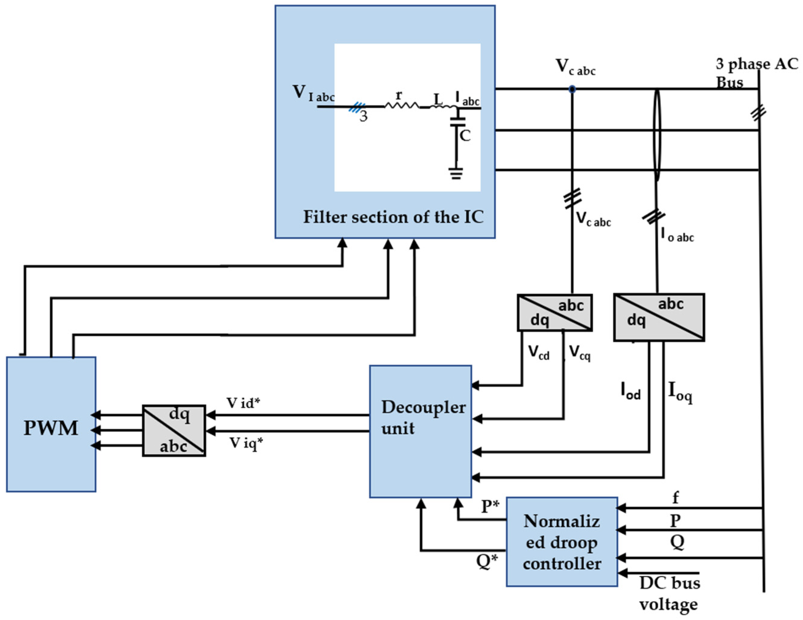
Figure 4 shows the proposed feedback-based decoupler control unit.
The three main blocks are the IC with the filter section, the decoupling matrix-based feedback control unit, and the normalized droop control unit. The normalized droop controller is the outermost control loop utilizing the normalized droop control strategy. The decoupler unit has two control loops—the outer power control loop and the inner voltage control loop. The modeling and designing of the controllers are detailed in the subsequent subsections.

3.1. Linearized Model of the IC with the Filter Section

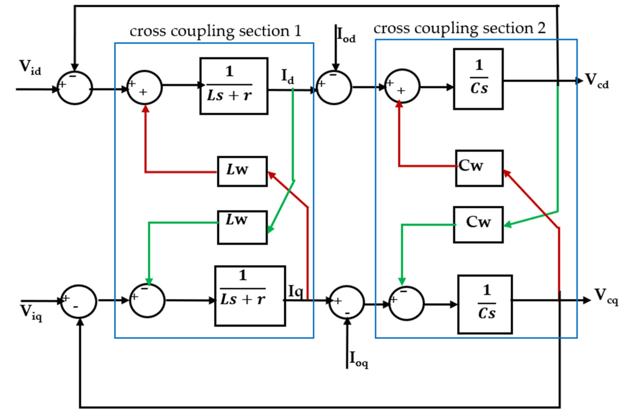
The linearized model of the IC with a filter section is shown in Figure 5. The differential equations governing the filter section are
V i   a b c = r I   a b c + L d d t I   a b c
I   a b c = I   o   a b c + C d d t V   c   a b c
L   d d t I d I q = r L w L w r I d I q + V i d   V c d   V i q   V c q  
C d d t V c d V c q = C w   V c q   C w   V c d   + I d I q I o d I o q
The voltage at the output of the filter section is  V   c   a b c V c d    and  V c q  are the respective d and q axes components of the filter output section  V   c   a b c V i d    and  V i q  are the d and q axes’ voltages, respectively, of the filter input  V i   a b c ,   I d  and  I q  are the d and q axes’ currents of Iabc, respectively, at the filter input section. Finally,  I o d  and  I o q  are the d and q axes’ currents, respectively, at the filter output section.
Assuming a symmetrical three-phase system, the equations in the dq- reference frame in the Laplace domain are obtained as described below:
    I d I q = 1 L s + r V i d   V c d   V i q   V c q   + 1 L s + r L w I q L w I d
V c d   V c q   = 1 C s C w V c q C w V c d + 1 C s I d   I o d   I q   I o q  
A systematic approach is taken to decouple the original cross-coupled model and derive the closed-loop transfer functions for the inner- and outer-loop control systems in the first-order time constant form. This makes our proposed model much simpler for analysis compared with higher order models. The model is validated for different transients in the AC and DC subgrids. The controller parameters are also optimized by the PSO algorithm. Furthermore, the controllers are validated for the design and optimized parameters in terms of error indices.

3.2. Design of Decoupling Matrix-Based Feedback Control Unit

The design and implementation of the decoupling-matrix based feedback control system are detailed in this section. Referring to Figure 5 and Equations (13) and (14), the terms  L w I q  acts as the disturbance from the q to d axes and  L w I d  serves the same function from the d to q axes. This cross-coupling will affect the transient behavior of the inner control loop. In order to cancel out the effect of cross-coupling, a systematic step-by-step procedure is proposed, which is based on the matrix diagonalization technique. After decoupling, feedback is introduced, and the transfer function of the closed-loop system is derived by direct synthesis. These steps are explained in detail as follows.
The linearized model of the filter shown in Figure 5 has two sections with cross-couplings. These sections are identified as Section 1 and Section 2. For Section 1 and Section 2, decoupling matrices were evaluated, which is explained in detail in Section 3.2.1. After obtaining a complete decoupled open-loop model for the d and q axes, feedback was introduced, and a compensator was designed for the desired response. A first-order transfer function is assumed for the closed-loop structure, and the compensator is designed by the direct synthesis method.

3.2.1. Design of Decoupling Matrices

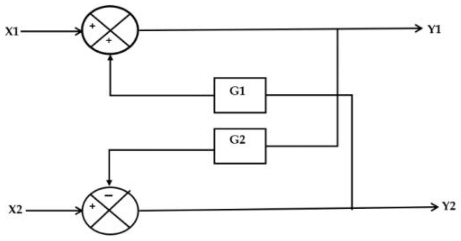
When considering a generalized two-input–two-output (TITO) system with cross-coupling (shown in Figure 6), the Y1 output is cross-coupled to the X2 input through G2, and the same is true for Y2 to X1 through G2. The systematic procedure for decoupling this structure is detailed below.
After applying the superposition principle, the output matrix is obtained as
Y 1 Y 2 = 1 1 + G 1 G 2 G 1 1 + G 1 G 2 G 2 s L + R 2 + L w 2 1 1 + G 1 G 2   X 1 X 2
Here, for Section 1,  G 1  =  G 2  =  L w s L + R ; hence, after substituting in the state model (Equation (15)), we obtain the state matrix A as GA
Y 1 Y 2 = s L + R 2 s L + R 2 + L w 2 L w s L + R s L + R 2 + L w 2 L w s L + R s L + R 2 + L w 2 s L + R 2 s L + R 2 + L w 2   X 1 X 2
To decouple this transfer function, we must find another matrix that will transform  G A  into a diagonal matrix. Let the decoupling matrix be  G B , such that
G A G B = 1 0 0 1
Therefore,  G B = G A 1  is obtained as
1 ω S L + R ω S L + R 1
Using the same approach, Section 2 can also be decoupled, and the transformation matrix is obtained as
1 ω s ω s 1
The decoupler structures for Sections 1 and 2 are shown in Figure 7a,b, respectively.

3.3. Design of the Closed-Loop Transfer Function Model by Direct Synthesis Method

  • The desired closed-loop transfer function for the inner voltage control loop and outer power control loop without time delay is assumed in the first-order time constant form as  G d  = 1/(1 + sτ).
  • Assuming the plant transfer function as Gp and the series compensator as Gc, the closed-loop transfer function is expressed in the form  G d  = ( G p   G c )/(1 +  G p   G c ).
  • Since  G d  and  G p  are known, we can derive the transfer function for  G c  in PI, PD, or PID forms.
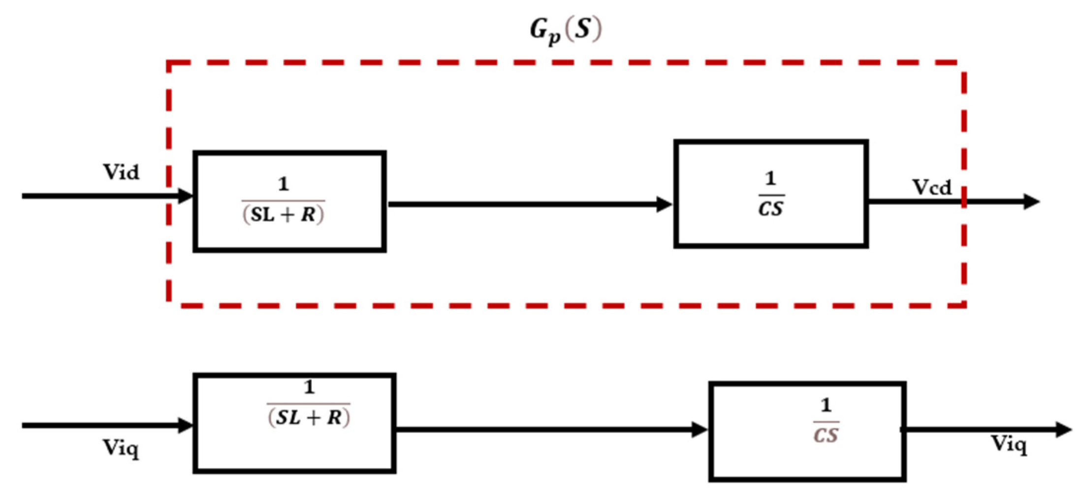
Based on the above steps, the overall transfer function of the interlinking converter is obtained in the first-order time constant form. By incorporating the decouplers for the cross-coupling Sections 1 and 2, the two-input–two-output cross-coupled system can now be replaced with two independent (decoupled) systems (Figure 8).
Hence, the open-loop plant transfer function is obtained as
G p = 1 s 2 L C + s R C
Now, introducing the originally removed negative feedback and placing a compensator with TF as  G C 1 , the closed-loop structure can be obtained (Figure 9).
Hence, the closed-loop transfer function becomes
G d 1 = Y S X S = V c d V i d = G p G C 1 1 + G p G C 1
where  G d 1  is the desired closed-loop TF of the inner control loop. Let  G d 1  be in the form of
G d 1 = 1 / ( 1 + s τ c )  
After substituting for  G P  and  G d 1 , we obtain  G C 1  =  ( s L C + R C ) / τ c . However, this is in proportional-derivative (PD) form, which is not realizable. To make this compensator realizable, a first-order filter with a time constant much less than one must be used in cascade.
Let the filter transfer function be  1 / ( 1 + s   τ f ) . Thus, after multiplying with the filter transfer function, we obtain
G C 1 = R C L s R + 1 1 + s   τ f τ c
Similarly, the closed-loop TF for  V c q   / V i q    is also obtained. Moreover, the outer power loop control can be obtained in the same direct synthesis method. Let the overall closed-loop transfer function be of the form  G d 2  =  1 / 1 + s   τ d
Similar calculations are carried out for  G c 2  and it is rewritten as
G c 2 = τ c   τ d + 1 s   τ d
This is of the form  K p  +  K i / s , where
K p = τ c   τ d   and   K i = 1 s   τ d
The values of  τ C   ,   τ f ,   τ d  are chosen as  10 4 ,   10 6 ,   a n d   10 3   , respectively. Therefore, Kp = 0.1 and Ki = 1000.
Figure 10 shows the control structure for the d-axis, where the inner voltage loop is replaced by the equivalent first-order transfer function, while Figure 11 shows the overall closed-loop transfer function of Figure 10.
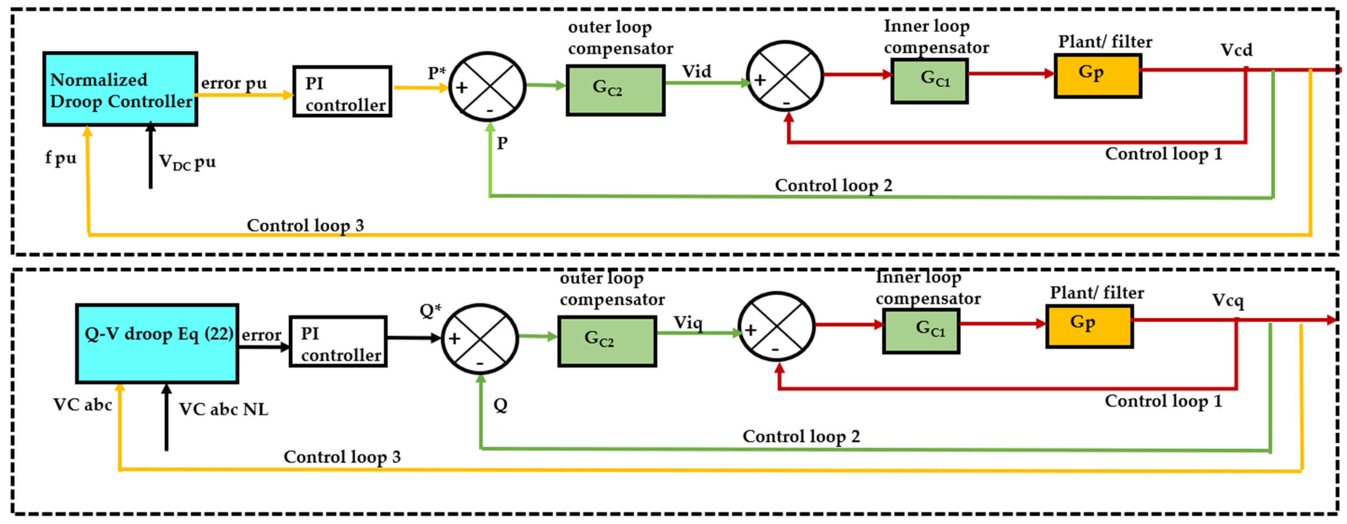
The coordinate normalized droop control unit inputs are the AC bus frequency and the DC bus voltage. Using Equations (7) to (9), the per-unit values of the frequency at the AC bus and voltage at the DC bus are generated. The error is processed through a PI controller to generate the reference active power command signal P*. The decoupling matrix-based feedback control unit has two control loops. The outer power control loop control and the inner voltage control loop. The output of this control unit produces the reference AC bus voltage,  V i   a b c  for the inverter.
The comprehensive control structure for both the d and q axes integrated with the normalized droop control is shown in Figure 12.
The difference between      f p u  and  V D C   p u  is proportional to the active power reference command of the outer power loop. Additionally, P* and Q* are calculated through Equations (21) to (23).
P = ( K P   + K i   / s )   e   p u
Q = K q ( V a b c   N L V C   a b c   )
e   p u = f p u V D C   p u
where  K P ,   K q ,   a n d   K i    can be realized with a P or PI controller, respectively, and  V C   a b c    and  V a b c   N L  are the AC bus terminal voltage at the PCC under loaded and no-loaded conditions, respectively. The outer power loop controller produces the reference power P* to be transferred from one subgrid to the other, and the inner voltage loop controller produces the three-phase AC reference voltage  V i   a b c    for the PWM. The inner voltage controller’s reference signal is produced by the feedback-based decoupler, which is the main contribution of our paper. The transfer functions are designed and summarized in Table 1, and the system parameters are included in Table 2.

4. Results and Discussions

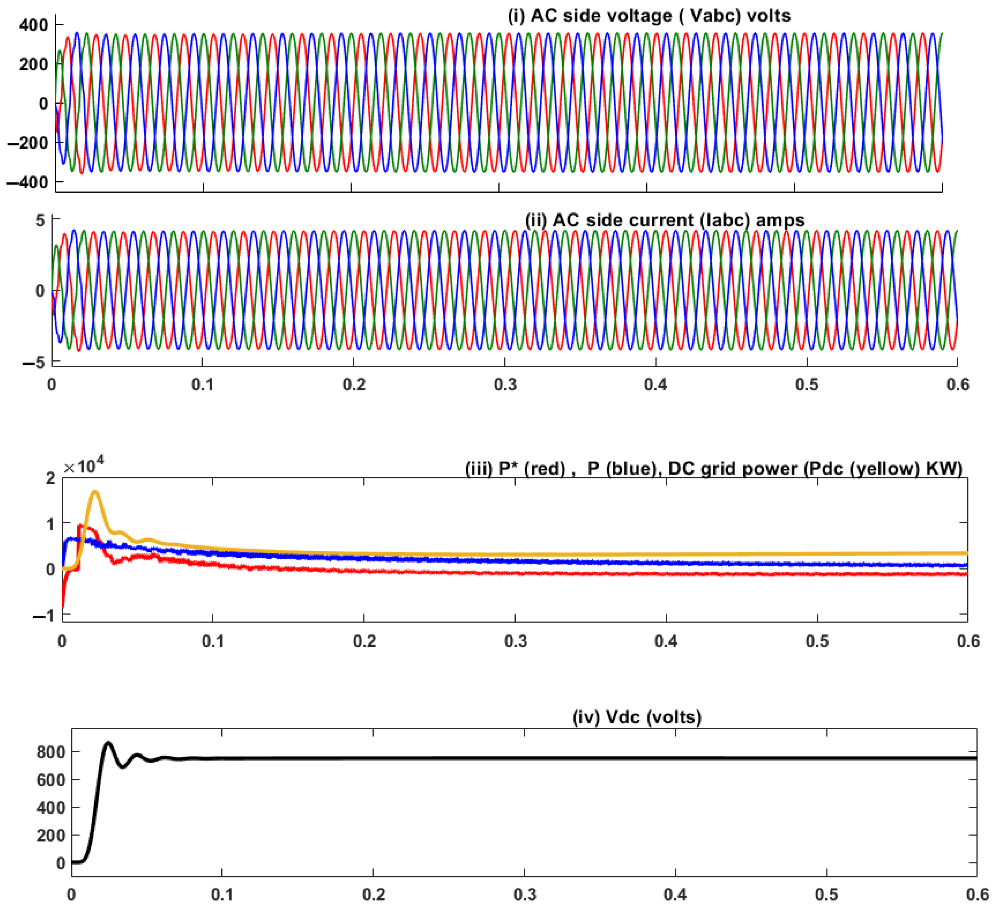
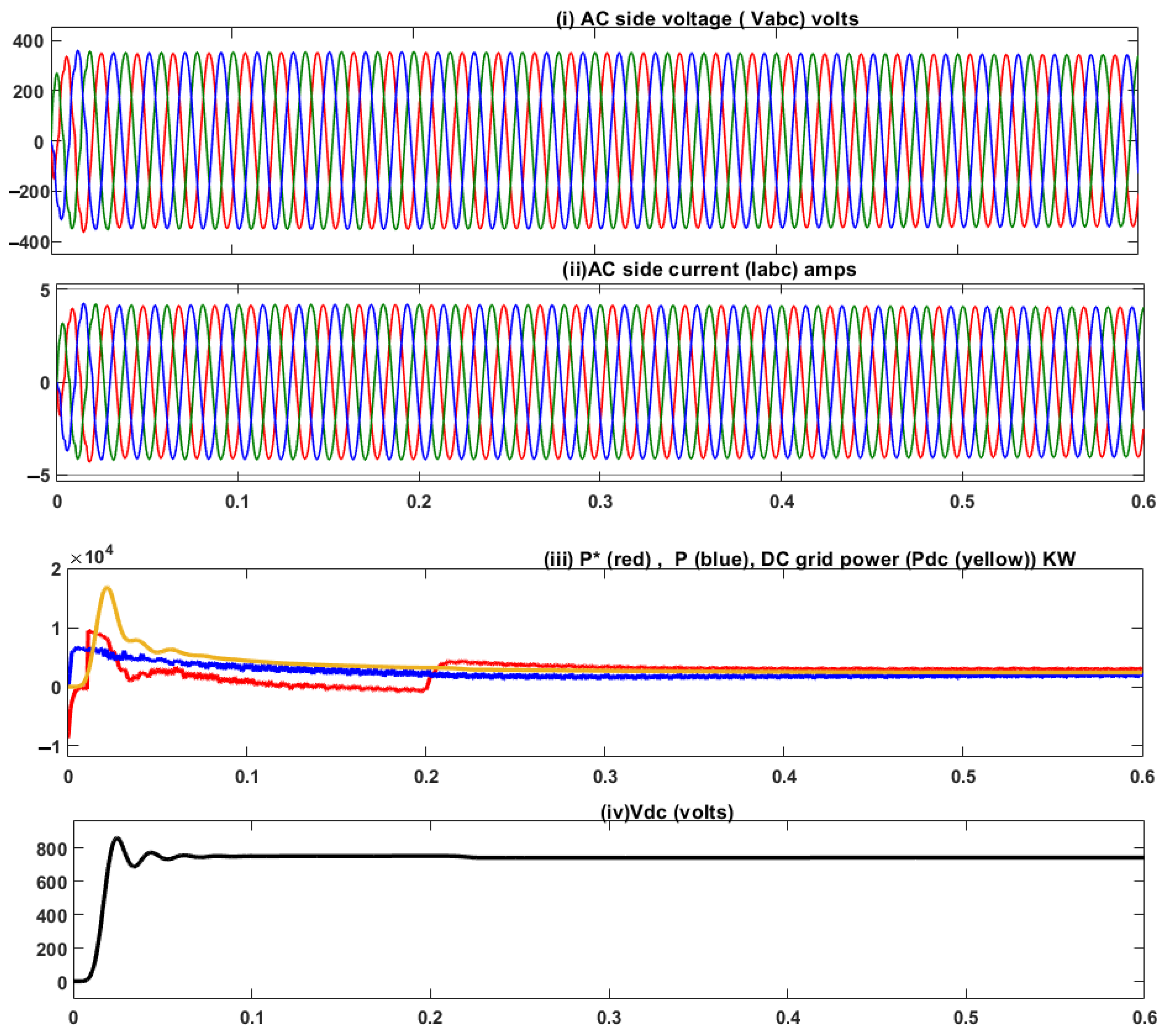
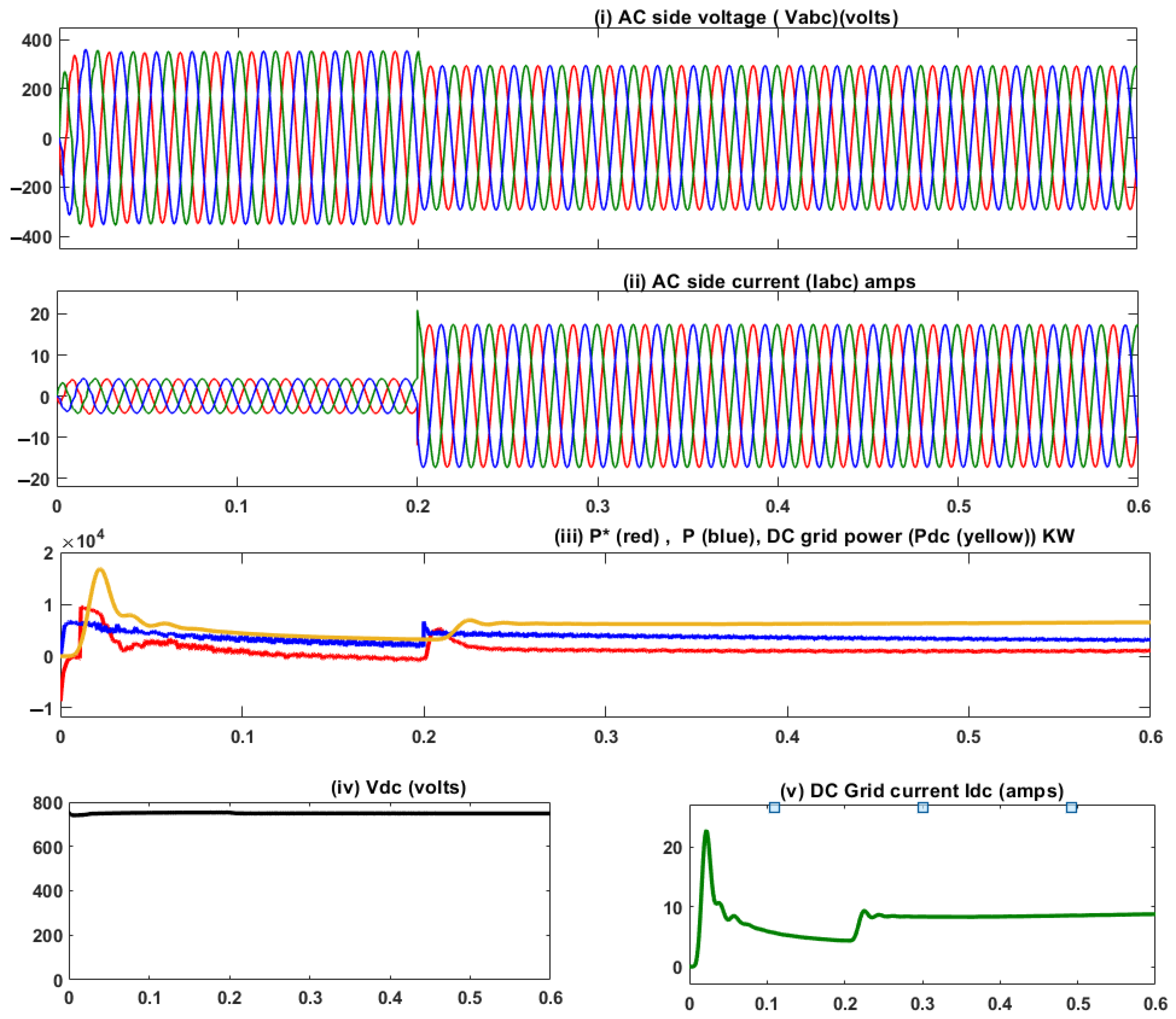
In this section, the efficacy of the decoupled controller model of the IC is tested for three different operating modes. The first case is the ideal mode of operation, where both the subgrids are underloaded and the IC practically transfers no power through it. Hence, the reference power signal is at the zero level. The corresponding results in this mode of operation are shown in Figure 13. Figure 13i shows the AC bus voltage, Figure 13ii shows the AC bus current, Figure 13iii shows the reference power, P*, for the IC, the ACside power P, and the DCside power Pdc, and Figure 13iv shows the DC bus voltage. The second case occurs in a situation when a transient is introduced at the DC side by loading it with an additional 10 KW. Similarly, the third case is introduced by additionally loading the AC side with a 10 KW load. The results corresponding to the second and the third cases are shown in Figure 14 and Figure 15, respectively. The T.H.D. analysis of the quality of the reference power signal is discussed in Section 4.1.1. The performance of the PI controller designed for the outer power control loop is validated in terms of error indices for both the designed controller parameter and P.S.O. based optimally tuned controller parameters.
For the ideal mode, no power will be transferred through the IC. When a transient occurs at the DC side at 0.2 s, the switching signal is positive, indicating power flow through the IC from the AC to the DC side. Similarly, when a transient is applied to the AC side at 0.2 s, while the DC side is under nominal operating conditions, the switching signal goes negative, indicating power flow through the IC from the DC to the AC side. The first transient occurs when the subgrids are loaded at 2 KW each. Because each sub-grid can manage its loads, the interlinking converter will not transfer any active power between them. This is validated by the waveform showing the reference power P*. P* remains close to zero for this transient event, indicating no power transfer between the sub-grids. This is illustrated in Figure 13i–iv. Figure 14i–iv also shows the second transient event when the DC subgrid is subjected to an additional 10 KW load at 0.2 s, which is clearly indicated by the increase in the reference power signal P*, as the interlinking converter transfers nearly 5 KW from the AC to the DC side.
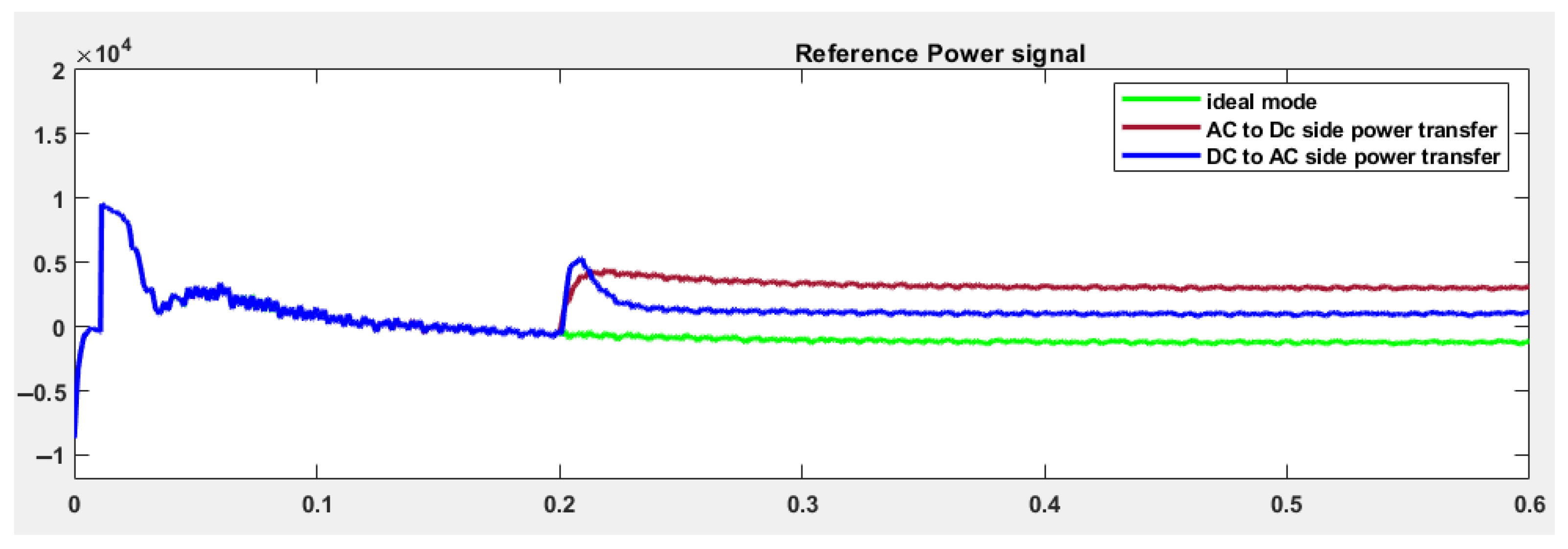
This is substantiated by the result indicating that the DC subgrid power is not increasingly subject to the transient. Instead, there is a decrease, indicating that it is receiving power from the AC subgrid. Figure 15i–v shows the third transient at 0.2 s when the AC side is subjected to a sudden load change from 2 KW to 10 KW and the DC side is at 2 KW. The results show that the reference power signal immediately changes its direction compared with the previous transient, setting the reference at 5.3 KW, which needs to be transferred from the DC side to the AC side. This is reinforced in Figure 15iii,v, which show the DC grid power and current increases following the transient. At the same time, the AC grid current has a reversal after the transient event, indicating current flow from the DC side to the AC side. The reference power signals used for deriving the control signal of the interlinking converter are shown in Figure 16 for the three cases of operation.

4.1. Analysis of Results

4.1.1. T.H.D Analysis

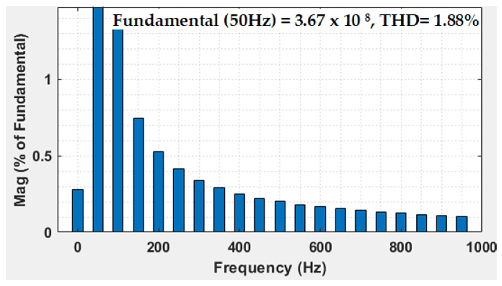
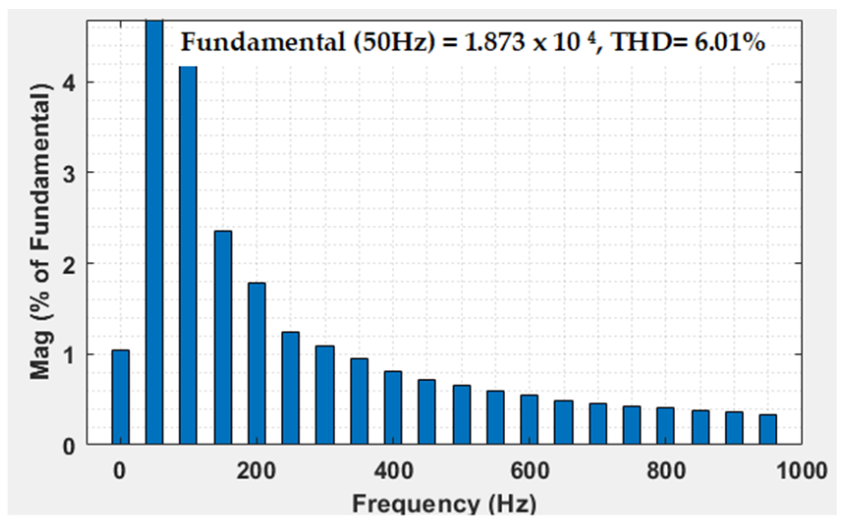
Figure 17 and Figure 18 show the quality of the control signal with and without the decoupler in terms of T.H.D. The results clearly indicate the supremacy of the model with the decoupler regarding quality, which is directly linked to transient stability. The T.H.D. is reduced to 1.88% with the proposed control compared with 6.01% without the decoupler.

4.1.2. Comparison of Error Indices with the Designed Controller Parameters and Optimal Parameters

The PI controller parameters were finally optimized with P.S.O. optimization, and the error indices of the controller were subjected to step inputs for the designed and optimized values, which are shown in Table 3.

5. Conclusions

The designed feedback-based decoupler control system is highly effective when responding to transients in active power demand and generating control signals, ensuring stability within both subgrids. Although normalized coordinate droop control strategies have been widely explored in research over the past few years, this approach has novelty because each of the control loops is derived as a first-order transfer function, which greatly simplifies modeling complexity. This ensures a faster response as well as smooth control signals, thereby ensuring higher quality voltage, current, and power signals. Hence, the proposed strategy differs from the existing strategies in the sense that the reference power signal is derived completely from the perfect decoupled model, ensuring a high-quality control signal. The main reason for achieving this result is because cross-coupling additionally induces an impedance effect at the output of the inverter, significantly contributing to overall impedance and leading to voltage and frequency instability. In this work, perfect decoupling of the voltage vectors was achieved by the matrix diagonalization strategy. Additionally, the tuning of the droop coefficients was not addressed in this context, whereas emphasis was laid on enhancing the existing coordinate control process in hybrid microgrids with the proposed strategy. This work differs from other related works involving decoupling strategy in the sense that feedback-based decoupling is a new idea. In the literature, feed-forward control is utilized for compensating for the cross-coupling effect. Furthermore, the power controller is validated in terms of IAE, ISE, and ITSE by comparing the performance with optimized gain and design parameters (presented in Table 3). The results indicate that the designed decoupler-based feedback control can be integrated with existing droop control strategies for the desired microgrid operation. Based on the results achieved, the feedback-based decoupled control exhibits an almost ideal control action for different modes of operation of the IC. Further expansion of this work is possible by utilizing the internal model control method for the synthesis of the transfer function model for the control loops. This can be compared with the performance obtained with the direct synthesis approach. Finally, another scope for further expansion of the proposed system that can be tested is its effectiveness in the grid-connected mode either as a grid-supporting or grid-forming unit.

Author Contributions

Conceptualization, K.P. and R.P.N.; methodology, K.P. and R.P.N.; software, R.P.N.; validation, K.P. and R.P.N.; formal analysis, K.P.; investigation, K.P. and R.P.N.; resources, K.P. and R.P.N.; writing—K.P. and R.P.N.; supervision, K.P.; project administration, K.P. All authors have read and agreed to the published version of the manuscript.

Funding

This research received no external funding.

Data Availability Statement

No new data were created or analyzed in this study. Data sharing is not applicable to this article.

Conflicts of Interest

The authors hereby declare that there are no potential conflict of interest in this paper. The authors also declare that there are no competing financial interests or personal relationships that could have appeared to influence the work reported in this paper.

References

  1. Shahgholian, G. A brief review on microgrids: Operation, applications, modeling, and control. Int. Trans. Electr. Energy Syst. 2021, 31, e12885. [Google Scholar] [CrossRef]
  2. Tabatabaei, N.M.; Kabalci, E.; Bizon, N. (Eds.) Microgrid Architectures, Control and Protection Methods; Springer: Berlin/Heidelberg, Germany, 2019. [Google Scholar]
  3. Nithara, P.V.; Anand, R. Comparative analysis of different control strategies in Microgrid. Int. J. Green Energy 2021, 18, 1249–1262. [Google Scholar]
  4. Bharath, K.R.; Choutapalli, H.; Kanakasabapathy, P. Control of bidirectional DC-DC converter in renewable based DC microgrid with improved voltage stability. Int. J. Renew. Energy Res. 2018, 8, 871–877. [Google Scholar]
  5. Sanampudi, N.; Kanakasabapathy, P. Integrated voltage control and frequency regulation for stand-alone micro-hydro power plant. Mater. Today Proc. 2021, 46, 5027–5031. [Google Scholar] [CrossRef]
  6. Mishra, S.; Viral, R.K. Introduction to Hybrid AC/DC Microgrids. In Microgrids; Academic Press: Cambridge, MA, USA, 2022; pp. 159–189. [Google Scholar]
  7. Wang, P.; Xiao, J.; Jin, C.; Han, X.; Qin, W. Hybrid ac/dc Micro-Grids: Solution for High Efficient Future Power Systems. In Sustainable Power Systems; Springer: Singapore, 2017; pp. 23–40. [Google Scholar]
  8. Barik, A.K.; Jaiswal, S.; Das, D.C. Recent trends and development in hybrid microgrid: A review on energy resource planning and control. Int. J. Sustain. Energy 2021, 41, 308–322. [Google Scholar] [CrossRef]
  9. Sreelekshmi, R.S.; Amitha, P.; Manjula, G.N. Control and operation of microgrid connected Hybrid Energy Storage System. In Proceedings of the 2016 International Conference on Energy Efficient Technologies for Sustainability (ICEETS), Nagercoil, India, 7–8 April 2016; IEEE: New York, NY, USA, 2016. [Google Scholar]
  10. Song, Y.; Hill, D.J.; Liu, T. Impact of DG connection topology on the stability of inverter-based microgrids. IEEE Trans. Power Syst. 2019, 34, 3970–3972. [Google Scholar] [CrossRef]
  11. Elmouatamid, A.; Ouladsine, R.; Bakhouya, M.; El Kamoun, N.; Khaidar, M.; Zine-Dine, K. Review of control and energy management approaches in micro-grid systems. Energies 2020, 14, 168. [Google Scholar] [CrossRef]
  12. Rangu, S.K.; Lolla, P.R.; Dhenuvakonda, K.R.; Singh, A.R. Recent trends in power management strategies for optimal operation of distributed energy resources in microgrids: A comprehensive review. Int. J. Energy Res. 2020, 44, 9889–9911. [Google Scholar] [CrossRef]
  13. Eajal, A.A.; Yazdavar, A.H.; El-Saadany, E.F.; Ponnambalam, K. On the Loadability and Voltage Stability of Islanded AC–DC Hybrid Microgrids During Contingencies. IEEE Syst. J. 2019, 13, 4248–4259. [Google Scholar] [CrossRef]
  14. Eajal, A.A.; Muda, H.; Aderibole, A.; Al Hosani, M.; Zeineldin, H.; El-Saadany, E.F. Stability evaluation of AC/DC hybrid microgrids considering bidirectional power flow through the interlinking converters. IEEE Access 2021, 9, 43876–43888. [Google Scholar] [CrossRef]
  15. Khodabakhsh, J.; Moschopoulos, G. Simplified hybrid AC–DC microgrid with a novel interlinking converter. IEEE Trans. Ind. Appl. 2020, 56, 5023–5034. [Google Scholar] [CrossRef]
  16. Shen, X.; Tan, D.; Shuai, Z.; Luo, A. Control Techniques for Bidirectional Interlinking Converters in Hybrid Microgrids: Leveraging the advantages of both ac and dc. IEEE Power Electron. Mag. 2019, 6, 39–47. [Google Scholar] [CrossRef]
  17. Wang, Y.; Xu, Q.; Guerrero, J.M. Effect of frequency coupling on stability analysis of a grid-connected modular multilevel converter system. Energies 2021, 14, 6580. [Google Scholar] [CrossRef]
  18. Wang, L.; Fu, X.; Wong, M.-C.W. Operation and Control of a Hybrid Coupled Interlinking Converter for Hybrid AC/Low Voltage DC Microgrids. IEEE Trans. Ind. Electron. 2020, 68, 7104–7114. [Google Scholar] [CrossRef]
  19. Wang, X.; Blaabjerg, F.; Wu, W. Modeling and analysis of harmonic stability in an ac power-electronics-based power system. IEEE Trans. Power Electron. 2014, 29, 6421–6432. [Google Scholar] [CrossRef]
  20. Wang, X.; Blaabjerg, F.; Chen, Z. Autonomous control of inverter-interfaced distributed generation units for harmonic current filtering and resonance damping in an islanded microgrid. IEEE Trans. Ind. Appl. 2013, 50, 452–461. [Google Scholar] [CrossRef] [Green Version]
  21. Nair, D.R.; Nair, M.G.; Thakur, T. A Smart Microgrid System with Artificial Intelligence for Power-Sharing and Power Quality Improvement. Energies 2022, 15, 5409. [Google Scholar] [CrossRef]
  22. Hussain, M.N.; Melath, G.; Agarwal, V. An Active Damping Technique for PI and Predictive Controllers of an Interlinking Converter in an Islanded Hybrid Microgrid. IEEE Trans. Power Electron. 2020, 36, 5521–5529. [Google Scholar] [CrossRef]
  23. Khongkhachat, S.; Khomfoi, S. A Sliding Mode Control Strategy for a Grid-Supporting and Grid-Forming Power Converter in Autonomous AC Microgrids. Int. Rev. Electr. Eng. 2019, 14, 118. [Google Scholar] [CrossRef]
  24. John, G.K.; Sindhu, M.R.; Nambiar, T.N.P. Hybrid VSI Compensator for AC/DC Microgrid. In 2019 IEEE Region 10 Symposium (TENSYMP); IEEE: New York, NY, USA, 2019; pp. 738–743. [Google Scholar]
  25. Aryani, D.R.; Song, H. Coordination control strategy for AC/DC hybrid microgrids in stand-alone mode. Energies 2016, 9, 469. [Google Scholar] [CrossRef] [Green Version]
  26. Hu, J.; Shan, Y.; Xu, Y.; Guerrero, J.M. A coordinated control of hybrid ac/dc microgrids with PV-wind-battery under variable generation and load conditions. Int. J. Electr. Power Energy Syst. 2018, 104, 583–592. [Google Scholar] [CrossRef] [Green Version]
  27. Suchetha, C.; Ramprabhakar, J. Optimization Techniques for Operation and Control of Microgrids–Review. J. Green Eng. 2018, 8, 621–644. [Google Scholar] [CrossRef] [Green Version]
  28. Ramezani, M.; Li, S.; Golestan, S. Analysis and controller design for stand-alone VSIs in synchronous reference frame. IET Power Electron. 2017, 10, 1003–1012. [Google Scholar] [CrossRef]
  29. Nguyen, T.H.; Van, T.L.; Nawaz, A.; Natsheh, A. Feedback Linearization-Based Control Strategy for Interlinking Inverters of Hybrid AC/DC Microgrids with Seamless Operation Mode Transition. Energies 2021, 14, 5613. [Google Scholar] [CrossRef]
  30. Rezaei, M.H.; Akhbari, M. Power decoupling capability with PR controller for Micro-Inverter applications. Int. J. Electr. Power Energy Syst. 2021, 136, 107607. [Google Scholar] [CrossRef]
  31. Aljohani, T.M.; Ebrahim, A.F.; Mohammed, O. Hybrid microgrid energy management and control based on metaheuristic-driven vector-decoupled algorithm considering intermittent renewable sources and electric vehicles charging lot. Energies 2020, 13, 3423. [Google Scholar] [CrossRef]
  32. Azab, M. High performance decoupled active and reactive power control for three-phase grid-tied inverters using model predictive control. Prot. Control. Mod. Power Syst. 2021, 6, 25. [Google Scholar] [CrossRef]
  33. Li, B.; Zhou, L. Power decoupling method based on the diagonal compensating matrix for VSG-controlled parallel inverters in the microgrid. Energies 2017, 10, 2159. [Google Scholar] [CrossRef] [Green Version]
  34. Zhang, P.; Zhao, H.; Cai, H.; Shi, J.; He, X. Power decoupling strategy based on ‘virtual negative resistor for inverters in low voltage microgrids. IET Power Electron. 2016, 9, 1037–1044. [Google Scholar] [CrossRef]
  35. Wang, C.; Deng, C.; Li, G. Control Strategy of Interlinking Converter in Hybrid Microgrid Based on Line Impedance Estimation. Energies 2022, 15, 1664. [Google Scholar] [CrossRef]
  36. Wang, H.; Li, W.; Yue, Y.; Zhao, H. Distributed Economic Control for AC/DC Hybrid Microgrid. Electronics 2021, 11, 13. [Google Scholar] [CrossRef]
  37. Sun, L.; You, F. machine learning and data-driven techniques for the control of smart power generation systems: An uncertainty handling perspective. Engineering 2021, 7, 1239–1247. [Google Scholar] [CrossRef]
Figure 1. Hybrid microgrid.
Designs 07 00091 g001
Figure 2. Block diagram of the proposed system.
Designs 07 00091 g002
Figure 3. Merged droop characteristics.
Designs 07 00091 g003
Figure 4. Feedback-based decoupling control.
Designs 07 00091 g004
Figure 5. Linearized model of the filter section.
Designs 07 00091 g005
Figure 6. Generalized TITO system with cross-coupling.
Designs 07 00091 g006
Figure 7. (a) Decoupler for Section 1. (b) Decoupler for Section 2.
Designs 07 00091 g007
Figure 8. Decoupled SISO system.
Designs 07 00091 g008
Figure 9. Closed-loop structure.
Designs 07 00091 g009
Figure 10. Closed-loop structure with transfer function.
Designs 07 00091 g010
Figure 11. Overall closed loop transfer function model.
Designs 07 00091 g011
Figure 12. Comprehensive control structure for both d and q axes.
Designs 07 00091 g012
Figure 13. (i) AC bus voltage (case 1); (ii) AC bus current (case 1); (iii) reference power P*(case 1), ACside power P (case 1), DCside power Pdc (case 1); (iv) DC bus voltage (case 1).
Designs 07 00091 g013
Figure 14. (i) AC bus voltage (case 2); (ii) AC bus current (case 2); (iii) reference power P* (case 2), AC side power P (case 2), DC side power Pdc (case 2); (iv) DC bus voltage (case 2).
Designs 07 00091 g014
Figure 15. (i) AC bus voltage (case 3); (ii) AC bus current (case 3); (iii) reference power P* (case 3), ACside power P (case 3), DCside power Pdc (case 3); (iv) DC bus voltage (case 3); (v) DC grid current (case 3).
Designs 07 00091 g015
Figure 16. The reference power signals for the three cases.
Designs 07 00091 g016
Figure 17. T.H.D. analysis with decoupling.
Designs 07 00091 g017
Figure 18. T.H.D. analysis without decoupling.
Designs 07 00091 g018
Table 1. Transfer Functions of various blocks of the proposed control system.
BlockTransfer Function
Plant/Filter G p = 1 2.04   ×   10 7 s 2   +   0.0012 s   +   1
Compensator for control loop1
(inner voltage control)
G C 1 =   R C L s R   +   1 1   +   s   τ f τ c
where ,   τ C = 10 4   and   τ f = 10 6
Closed loop transfer function of
inner voltage control
G d 1 = 1 1   +   s τ c
Filter transfer function in series with  G C 1 1 1   +   s   τ f
Compensator for control loop2
(outer power control)
G c 2 = τ c   τ d + 1 s   τ d
where,  τ d = 10 3
Overall closed loop transfer function of inner voltage control and outer power control. G d 2 = 1 1   +   s τ d
Table 2. System Parameters.
ParameterValue
R10 ohms
L0.0017 H
C1.2 × 10−4 F
V   c   a b c  (Nominal amplitude)325 V
VDC
(Nominal Value)
750 V
DC side Capacitor4800 × 10 −6 F
Rated Power (DC side)10 KW
Table 3. Error indices with designed values and optimized values.
PI Controller ParametersIntegral Square Error
(ISE)
Integral Absolute Square Error (IAE)Integral
Absolute Time
Square Error (ITSE)
With designed values.
Kp = 0.1 and Ki = 1000
0.00090750.0015686.27 × 10−7
With optimized values tuned by P.S.O.
Kp = 814.7 and Ki = 905.79
7.48 × 10−70.00011716.45 × 10−9
Disclaimer/Publisher’s Note: The statements, opinions and data contained in all publications are solely those of the individual author(s) and contributor(s) and not of MDPI and/or the editor(s). MDPI and/or the editor(s) disclaim responsibility for any injury to people or property resulting from any ideas, methods, instructions or products referred to in the content.