1. Introduction
Several catastrophic accidents involving steam boilers and pressurised vessels in the early twentieth century led to the formation of the American Society of Mechanical Engineers (ASME) in 1911. The first code of rules for pressure vessels, titled “Rules for the Construction of Unfired Pressure Vessels”, was published in 1925. Pressure vessels are closed containers that hold gases or liquids at a pressure different from that of the surrounding air. To ensure safe operation, design codes such as the ASME Boiler and Pressure Vessel Code in North America, the EU’s Pressure Equipment Directive (PED), the Japanese Industrial Standard (JIS), CSA B51 in Canada, and AS1210 in Australia are in place.
Pressure vessels play a critical role in numerous industries, including the storage and transportation of dangerous liquids or pressurised fluids. However, improper design and manufacturing of these vessels can lead to hazardous incidents such as explosions and leakage, posing significant risks to both human life and the environment. Therefore, ensuring the safe design of pressure vessels is of utmost importance.
In this study, we aim to take a new approach to designing and analysing a typical vertical pressure vessel with a capacity of 10 m3 for storing pressurised LPG, following the guidelines provided by the American Society of Mechanical Engineers (ASME) code and FEA techniques. Safety is the primary concern to address in pressure vessel design, considering the potential risks associated with accidents. Our main goal is to develop a pressure vessel design that ensures the highest level of safety and minimises the risk of failure.
The pressure vessel under consideration is a cylindrical shell with two elliptical heads, two nozzles, a manway, and four leg supports. The design process involves geometric modelling using Autodesk Inventor Professional 2023, followed by finite element analysis (FEA) using Inventor Nastran. FEA allows us to investigate the displacements, deflections, and von Mises stresses in the pressure vessel, providing insights into its structural behaviour under various loading conditions.
By employing the finite element method, we can identify potential stress points in the pressure vessel and make necessary modifications to enhance its safety. The study explores the relationship between various factors such as displacement, stress, and shell thickness of the tank section. We carefully consider the permissible pressures and determine the required wall thickness to ensure acceptable maximum stresses. The results of our analysis demonstrate that the design is safe from failure, with the highest stresses observed in the manway, followed by the shell. The heads, nozzles, and leg supports experience lower stresses.
Through our analysis, we identified stress concentrations within the pressure vessel and proposed structural modifications to mitigate these stress levels. Notably, we found that the displacement within the vessel exhibited an inverse relationship with the tank section shell thickness, indicating the need for an appropriate shell thickness to reduce stress. Additionally, we observed that the factor of safety increased linearly with shell thickness, underscoring the importance of selecting an adequate thickness to maintain structural integrity.
In addition to the FEA analysis, we also perform theoretical calculations for the entire pressure vessel model to validate the results and ensure they fall within acceptable limits. This comprehensive approach ensures that the pressure vessel design meets the necessary safety requirements and mitigates the potential hazards associated with improper design and manufacturing.
The significance of this research lies in its focus on safety considerations and adherence to the ASME code throughout the design and analysis process. By following established standards and employing advanced computational tools such as FEA, we aim to ensure the integrity and reliability of the pressure vessel.
The novelty of our approach lies in the combination of utilising Autodesk Inventor Professional for geometric modelling and Inventor Nastran for FEA analysis, following the ASME code guidelines. By employing this integrated software solution, we can effectively simulate and evaluate the performance of the pressure vessel, identify potential stress concentration areas, and make design modifications to enhance its safety.
The main contributions of this study include:
Designing a vertical pressure vessel in accordance with the ASME code requirements, considering the specific characteristics and parameters of the LPG storage application.
Conducting a comprehensive FEA analysis to assess the structural behaviour of the pressure vessel under various loading conditions, including internal pressure, external loads, and thermal effects.
Evaluating the displacements, deflections, and von Mises stresses in the pressure vessel to identify critical areas that require design modifications for stress reduction.
Determining the optimum wall thickness of the pressure vessel to ensure acceptable maximum stresses while considering the permissible pressures.
Verifying the results through theoretical calculations and comparing them with the FEA results to ensure the design’s accuracy and adherence to safety standards.
Overall, this research contributes to the field of pressure vessel design and analysis by presenting a new approach that combines the application of the ASME code with FEA techniques. By utilising advanced software tools and following established industry standards, we can identify potential stress points, optimise the design, and ensure the safety and reliability of vertical pressure vessels.
Theoretically, pressure vessels can be almost any shape, but most are made of spheres, cylinders and cones. More complicated shapes have always been harder to figure out how to use safely and are usually much harder to build. The best shape for a pressure vessel, from a theoretical point of view, would be a sphere [
1].
A pressure vessel functions as a device where a pressure differential exists, resulting from atmospheric pressure. Due to the inherent danger associated with high operating pressures, meticulous attention must be paid during the design process of pressure vessels. The longevity of a pressure vessel subjected to cyclic loads is contingent upon the number and intensity of stress cycles it experiences. The durability of the vessel depends on its ability to withstand stress without experiencing failure [
2].
Since it is assumed that the pressure vessel is a thin cylinder, the analysis follows the thin cylinder formulae. The modelling was performed with software called Autodesk Inventor Professional 2023, and a finite element analysis was performed to find the places where stress was most concentrated. As expected, the highest stress level is at the point where the nozzle is attached. This is conducted to study how stress can build up when the end of a high-pressure vessel is connected to a cone-shaped nozzle.
The main reason for this is that the cone-shaped nozzle must be attached separately. This method would cause the pressure vessel and nozzle to have different shapes at the point where they connect [
3]. Stress calculations were performed using the finite element method, and a parametric model was created. Multiple tests were conducted to examine different positions of the cylindrical nozzle on the pressure vessel, as well as various orientations of the connection rather than a centrally located radial hole [
4].
The conducted tests validated the fact that the actual stress value for the maximum permissible internal pressure varies depending on the attachment orientations, indicating the need for additional investigation to determine the most efficient connection. The mesh resolution of a finite element model finds its accuracy. If the mesh is coarse, the results will be less effective. We eventually reach the point of diminishing returns, where the quality of the mesh has no significant effect on the accuracy of the results. At this point, the mesh is said to have converged. As the mesh was refined, convergence was observed for all previously analysed models [
5].
The accuracy of the result improves as the number of nodes and elements increases. Based on the results of the analysis, the nozzle-to-pressure-vessel interface has the highest stress. Due to the abrupt change in geometry and stress level, a high-stress state of concentration develops. As has been seen, symmetry is a greater factor than certain nozzles. A symmetrical nozzle possesses extremely low stress and a low stress increment factor [
6].
Experiments and mathematical analysis were employed to determine the stress intensity factor at locations where crack propagation occurs on both the inner and outer surfaces of a cylindrical pressure vessel. The findings revealed a positive correlation between the length of the crack and the stress intensity factor. Strain gauges were utilised to measure displacements, while empirical formulas were applied to calculate stress intensity and correction factors. The results obtained from both theoretical analysis and experimental measurements demonstrated good agreement and consistency [
3].
In this study, the Inventor Nastran for finite element analysis is used to look at the parts of a pressure vessel. It talks about how to model different parameters in a cracked pressure vessel. It also gives a few rules for performing analysis with FEA, such as “starting with a simple design” and “using closed-form solutions for analysis”.
Sowiński [
7] examines the use of Kirchhoff-Love linear shell theory in analysing stress and deformations in cylindrical pressure vessels. The theory simplifies the analysis by treating the vessels as thin shells and neglecting certain effects. It supplies a mathematical framework for predicting stress and deformations. This paper focuses on the discussion of the theory’s formulation, assumptions, and validity for thin shells with small nonlinearities. The paper also evaluates the theory’s accuracy by comparing its results with experimental data or more refined numerical models. This investigation supplies insights into the application and limitations of shell theory in predicting the behaviour of cylindrical pressure vessels. Such knowledge is valuable for the design and analysis of typical vertical pressure vessels using the ASME Code and finite element analysis (FEA) techniques.
Devaraju and Pazhanivel [
8] performed a stress analysis on pressure vessels, considering internal pressure, self-weight, and fluid weight. The pressure vessel design was developed using manual calculations, and the computed stress values were compared with those obtained from ANSYS V12 software. The research findings indicated that the stress on the pressure vessel’s shell remained well below the allowable stress limit for the vessel material. Consequently, it was determined that the pressure vessel was safe for its intended application.
Patel et al. [
9] conducted an investigation into pressure vessels suitable for marine substation applications, considering various materials. The researchers performed a stress analysis to evaluate their structural integrity. By placing pressure vessels at different heights, the study examined the internal and external pressures exerted on these vessels at different ocean depths, utilising MATLAB R2013b software. The external pressure originated from the water pressure at specific depths, while the internal pressure resulted from the gas inside the vessel. The researchers concluded that the pressure vessel design effectively balanced the external pressure, indicating its suitability for marine applications.
Prasanth and Sachidananda [
10] conducted research on the design and analysis of pressure vessels, employing the finite element method. They divided the vessel into smaller elements to perform stress analysis under internal pressure. Principal stress theory and distortion energy theory were utilised to validate their design, and the calculated results were compared with those obtained from FEA software. The researchers concluded that the maximum principal stress obtained through manual calculations aligned with the FEA results, affirming the safety of the pressure vessel design.
Mali et al. [
11] conducted an analysis of a pressure vessel, adhering to ASME standards [
12] in material selection, design, and stress calculations. Their objective was to demonstrate that multilayer pressure vessels have the capability to withstand higher internal pressures compared to solid-wall vessels. The analysis of the pressure vessel encompassed the examination of different materials to minimise construction costs. The researchers concluded that the maximum stress experienced by the pressure vessel remained within the yield stress limit of the chosen material.
Pendbhaje et al. [
13] conducted a research study on the design and analysis of a pressure vessel, with a particular emphasis on analysing safety parameters for a specified working pressure. The researchers examined critical factors influencing the safety of the pressure vessel, including material selection, design considerations, and fabrication methods. Notably, they employed a design approach utilising seamless pipes instead of plate fabrication for the vessel shell. Their findings indicated that the maximum working pressure considered remained within the allowable limit, affirming the vessel’s safety for the intended application.
Ţălu and Ţălu [
14] conducted an analysis on a pressure vessel to compare the effects of using a flat head versus a hemispherical head. The study considered various orientations and different numbers of saddle supports. The researchers concluded that the von Mises and normal stresses in the pressure vessel were similar for both flat heads and hemispherical heads. However, they observed that the stress at the closure of the flat head was approximately twice as high as that of the hemispherical head vessel.
Wilde, Blain and Brebbia [
15] have studied the design and analysis of full composite pressure vessels using FEA. They studied several types of end domes for optimising the weight and material variation. They concluded that a composite material can be used to optimise the weight of pressure vessels.
In summary, this introduction provides an overview of pressure vessels, their historical development and the importance of design codes for ensuring safe operation. It highlights the significance of stress analysis in pressure vessel design, particularly focusing on the concentration of stress at the nozzle-to-pressure-vessel interface. The use of finite element analysis and experimental methods for stress intensity factor evaluation is discussed, as well as the application of Kirchhoff-Love linear shell theory. Various studies on stress analysis, material selection, and design optimization of pressure vessels are referenced, emphasizing the importance of safety considerations and compliance with industry standards.
2. Materials and Methods Using ASME Section VIII, Division 1
The design of the vertical pressure vessel will be conducted following ASME Section VIII, Division 1, which supplies guidelines and regulations for the design, fabrication, inspection, and testing of pressure vessels. This code ensures compliance with industry standards and the safety and integrity of the vessel under operating conditions [
12].
Lees [
16] focuses on hazard identification, assessment, and control within the process industries. It offers a comprehensive overview of various techniques and methodologies for showing hazards, evaluating risks, and implementing effective control measures. This edition emphasises the importance of safety management systems and supplies practical insights through case studies and examples. It is a valuable reference for professionals involved in process safety, offering guidance on preventing accidents, protecting personnel, and minimising the impact of potential incidents.
Following ASME Section VIII, Division 1, the design and analysis of the vertical pressure vessel consider the potential buckling phenomenon. Buckling is a critical failure mode that occurs when a thin-walled cylinder collapses in compression before reaching its ultimate compressive strength. This phenomenon is influenced by the geometry of the vessel and any imperfections in its shape.
The study conducted by Shen, Tang and Liu [
17] offers valuable information on the application of the finite element method (FEM) in buckling analysis. By integrating the guidelines specified in ASME Section VIII, Division 1 and incorporating the FEM approach, this research ensures a rigorous investigation of the pressure vessel’s structural integrity. The analysis encompasses the influence of geometric parameters, imperfections in shape, and loading conditions to accurately find critical buckling loads. The consideration of buckling effects in the
Section 2 contributes to a comprehensive assessment of the pressure vessel’s performance and reliability.
The standard code utilised in the design of vertical tanks (vessels) ensures that the smallest components of the tank meet the necessary design criteria and do not experience failures. The specialised code for the vessels is 0.1 MPa to 20 MPa, and most vertical vessels are used in this range [
8]. The cylindrical vertical pressure vessel is made up of the following parts: shell, head, nozzles, and base support. As a conceptual design, there are some first details provided in the technical description of the required vertical pressure vessel, as shown in
Table 1. The pressure vessel must also include a manway, inlet and blowdown outlet. There are no requirements for the interfaces these components connect to.
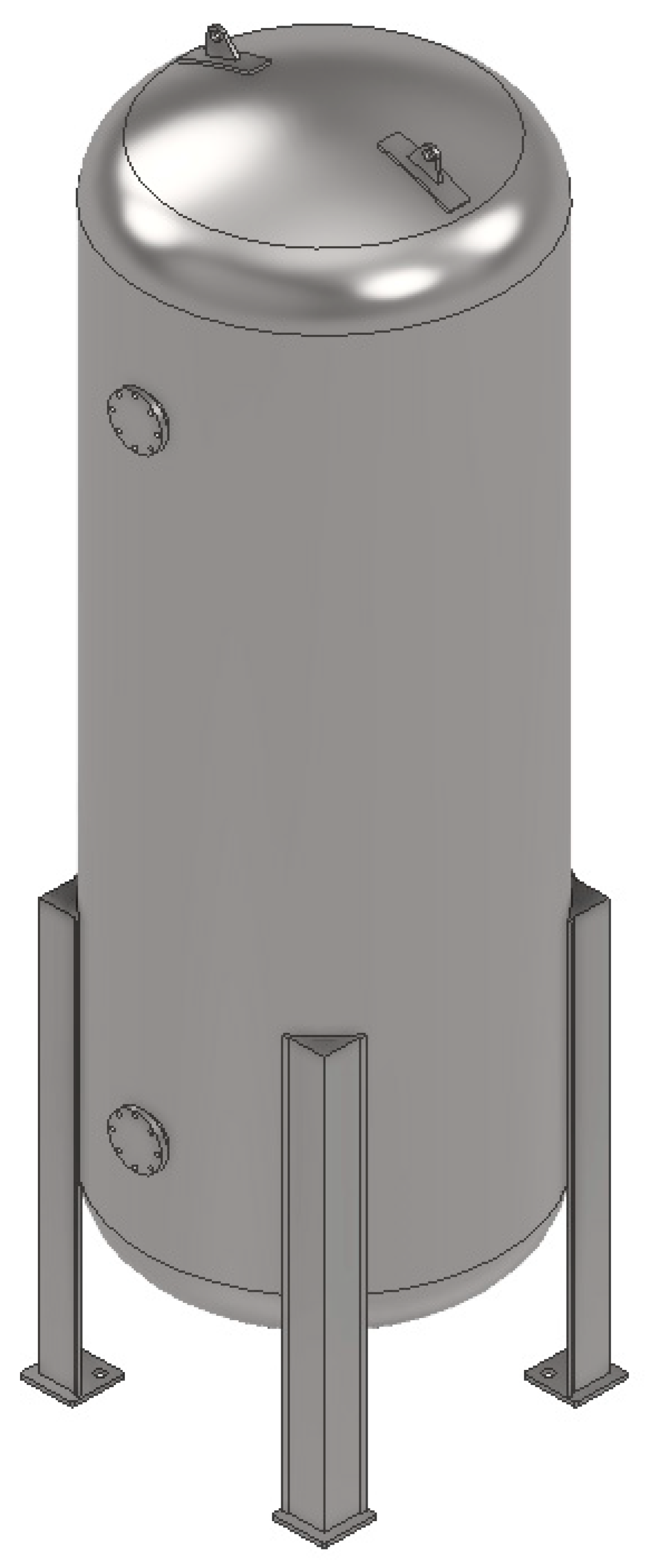
The pressure vessel chosen for this study is a pressure vessel used to hold liquefied petroleum gas (LPG). This pressure vessel has elliptical heads and is designed to be used in a fixed location on a leg support. The pressure vessel will have an inner shell diameter of (d) mm and a shell length of (L) mm, as shown in
Figure 1. The overall ability of the tank is driven by the design pressure for the required amount of liquid to be stored. The requirement states 10,000 L of LPG, not exceeding 1.55 MPa maximum pressure.
Assuming the LPG is 100% liquid, the cylindrical body of the tank needs to have a volume of 10,000 L, or 10 cubic meters.
Design pressure is 10% over maximum operating pressure.
Based on maximum design working pressure and using the following
Table 2 for optimum pressure vessel designs and the converted internal pressure, an L/D ratio of 3 is selected.
Optimum pressure vessel proportions are per the above (
Table 2) suggested L/D ratio of 3. The formula for volume is written as:
The formula for the L/D ratio is given as:
Substituting L into Volume:
Now, substituting r into Volume:
Therefore, this pressure vessel shall have the following conceptual design. Assuming a usage factor of 0.85 for thermal expansion and vapour volume, the volume needed is 11.76 m3. Initially, assume a cylinder with hemispherical ends (although for this ability, a spherical vessel could be used). For an L/D of 3, the overall initial dimensions shall be 5.4 m in length (cylinder length) and 1.75 m in diameter. This produces a volume of 11.59 m3 with an L/D ratio of 3.08. Large LPG vessels are typically horizontal or spherical, depending on the ability; however, a vertical pressure vessel is needed.
2.1. Mechanical Properties of Vessel Material
The structural integrity of pressure vessels is indeed influenced by temperature variations. Under elevated temperature conditions, the mechanical properties of the vessel material, typically steel, can deteriorate. This may result in a reduction in yield strength, stiffness, and modulus of elasticity, potentially leading to deflections, local buckling, and twisting of the vessel. This coupling of the structural model with a thermal model allows for a comprehensive understanding of the pressure vessel’s performance under extreme temperature conditions, such as exposure to high-temperature gases, liquids, jet fire, or pool fire.
The research studies by McKinley [
18] and Zozulya [
19] provide valuable insights into the analysis of transient thermal stresses in cylinders and heat transfer between shells and rigid bodies. These sources can enhance the research paper by supplying more theoretical background and methodologies related to the thermal-structural analysis of pressure vessels. Incorporating a thermal model and a structural model together introduces an added level of complexity, further complicating the analysis process. It requires obtaining correct and reliable thermal properties, such as heat transfer coefficients and material behaviour at elevated temperatures. Integrating these properties into the analysis would require additional data collection and potentially increase the computational burden. Given the limitations in time, resources, and ability, it is reasonable to focus on the structural analysis aspect while acknowledging the importance of temperature effects.
This study focuses primarily on the design and analysis of a typical vertical pressure vessel using the ASME Code and the FEA technique. Without specifically addressing the effects of elevated temperatures or fire events, it may be reasonable to exclude the thermal model. Future studies could consider the behaviour of pressure vessels storing high-temperature gases or liquids as well as their response to fire events such as jet fires or pool fires. Future research should aim to bridge the gap in understanding the thermal behaviour of pressure vessels and its relationship to structural integrity.
Since LPG is flammable, low-melting point materials such as aluminium and brass shall not be used as the main construction material. Therefore, carbon steel or stainless steel should be used.
Given that this is a large vessel (10,000 L) of high capacity and elevated temperature, it is important to consider the hazards relating to safety. The ASME Boiler and Pressure Vessel Code Section VIII states that low-melting point materials should not be used. LPG itself has an extremely low ignition temperature, which may compromise the vessel in a fire scenario. The vessel design must mitigate concentrated stress on the bottom end (since it is vertical) because LPG is twice as heavy as air, meaning it has a propensity to accumulate at the lowest levels. The hemispherical ends are typically more expensive to produce, and the detailed design may allow for tori-spherical or ellipsoidal ends, which are more commonly used.
The full height of the vessel will exceed 6.5 m when legs are added. It would be advantageous to investigate the wind loads and seismic loads on the vessel, but it is not required for this study.
The Explosives Act must be followed for this application because of the risk of fire and/or explosions. The flammability concentration with air for LPG is between 2% and 10%, so suitable storage and usage are imperative.
The pressure vessel shall be constructed using steel for its strength and weldability. Specifically, carbon steel is to be used: SA-516 Gr70 Steel Plate. Mechanical properties are shown below in
Table 3. This material follows the regulations in ASME Section VIII, Division 1 and the material specification and properties are given in
Table 4.
2.2. Shell Design
The ASME codes provide fundamental guidelines, as outlined in references [
10,
11], for designing shells in accordance with specific criteria. The primary focus is on determining the appropriate thickness of these shells, and welding operations are implemented when necessary to achieve the required thickness, ensuring that the stress levels remain within the permissible limits.
Allowable stress is calculated as per the ASME standards (1/3.5) × tensile strength [
9,
11]. In this study, the tensile strength is 484 MPa, so (1 × 484)/3.5 = 138 MPa, approx. Therefore, the allowable stress S for the SA-516 Gr70 steel plate is 138 MPa.
Note that E = 1.0 if a radiated test is used, whereas E = 0.7 if non-radiated tests are used.
In this study, E = 0.7 was selected for non-radiated tests. The used thickness equations are given below:
In this design study, for the case of circumference stresses (longitudinal welding), the variables are shown in
Table 5.
Where:
The calculated design material thickness should be 14 mm. This is not a commonly available material, so it should be rounded up to 14 mm thickness, which is more readily available from suppliers.
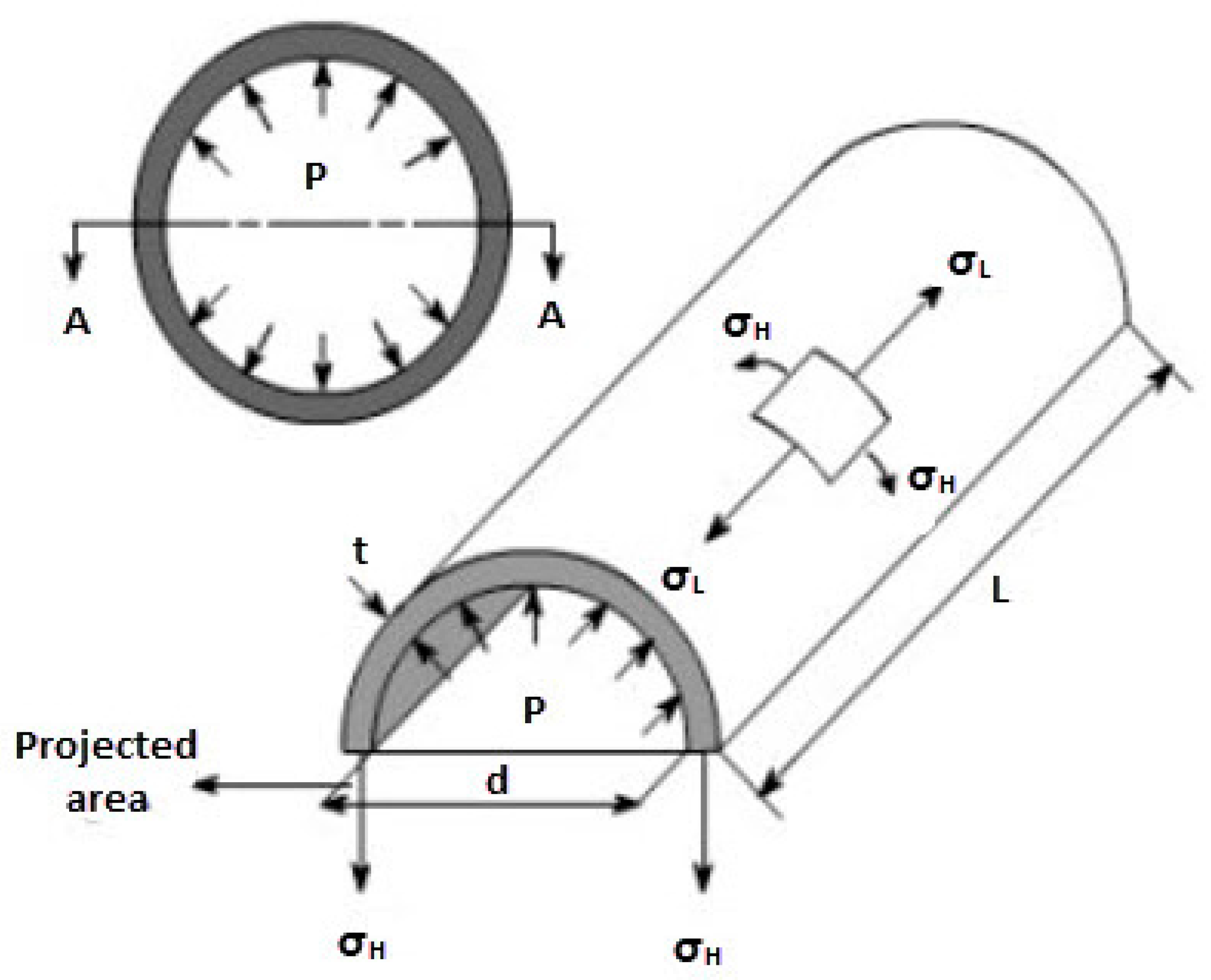
2.2.1. Circumferential Stress
The formula for circumferential stress can be written as follows:
where:
2.2.2. Longitudinal Stress
The formula for longitudinal stress can be written as follows:
where:
σL = Longitudinal stress
P = Design pressure
d = Internal diameter
t = Wall thickness
2.2.3. Circumferential Strain
From the material properties of A516 carbon steel, grade 70, extracting the values of the modulus of elasticity, E = 200 GPa.
Then, the formula for circumferential strain can be written as follows:
where:
εC = Circumferential strain
σc = Circumferential stress
E = Modulus of elasticity
2.2.4. Longitudinal Strain
From the material properties of A516 carbon steel, grade 70, extracting the values of the modulus of elasticity, E = 200 GPa.
Then, the formula for longitudinal strain can be written as follows:
where:
2.2.5. Diameter Change
The formula for circumferential strain can be written in another form, as follows:
Therefore, rearranging Equation (19) to define the diameter change, the change in diameter can be written as follows:
where:
2.2.6. Length Change
The formula for longitudinal strain can be written in another form, as follows:
Therefore, rearranging Equation (21) to define the shell length change, the change in length can be written as follows:
where:
2.3. Head Design
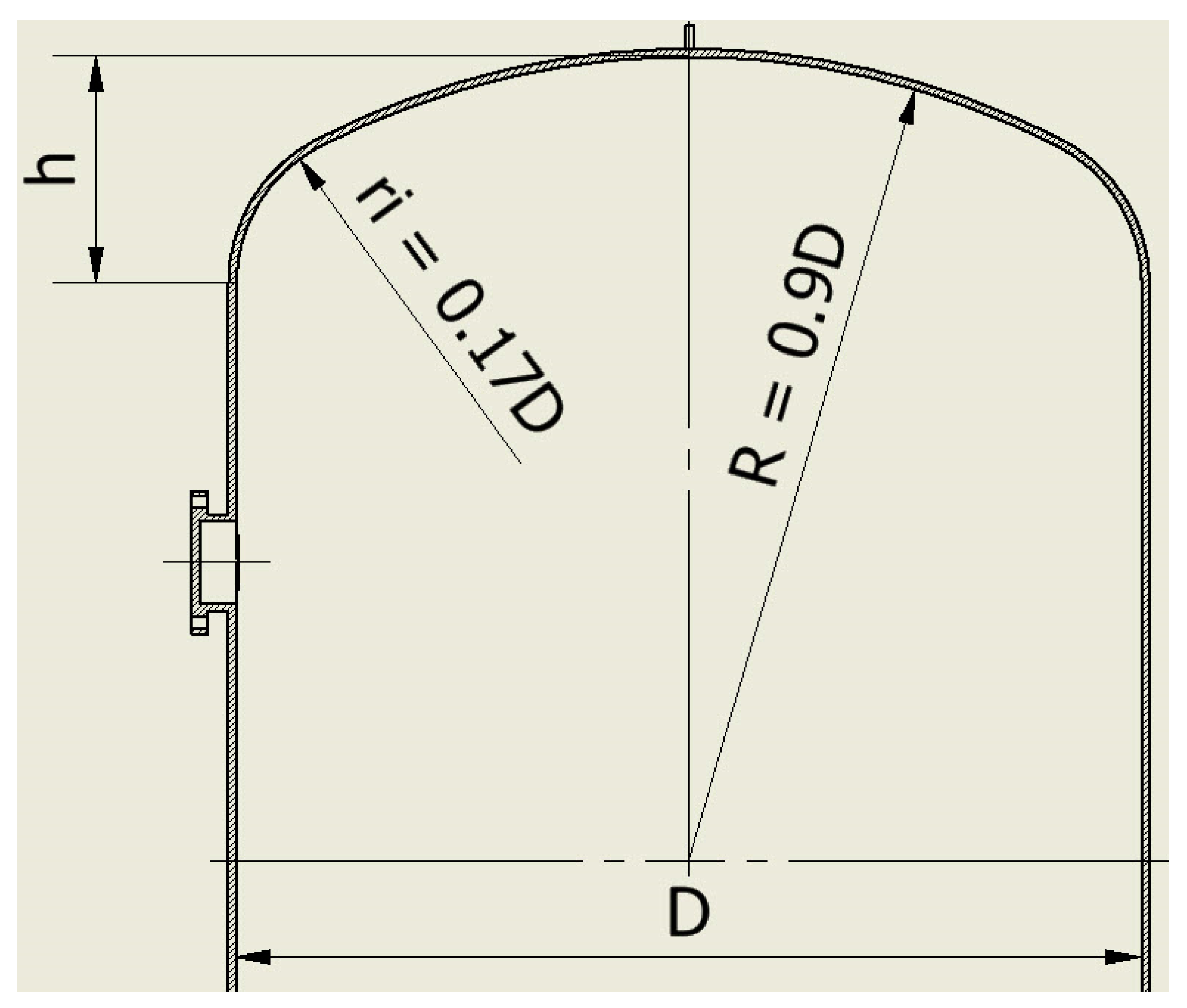
In order to withstand pressure, minimise thickness, and reduce costs, the majority of closing heads employed in pressure vessels are designed with a curved shape. There are various types of closing heads available, with semi-elliptical heads being the most commonly used option. In this study, the base diameter to the height was D/h = 4/1. The head cover will consist of two main parts, as shown in
Figure 2.
Spherical radius = R = 0.9 × D = 0.9 × 1.62 = 1.458 m.
Radius of the neck = r
i = 0.17 × D = 0.17 × 1.62 = 0.275 m.
For the required thickness, when the stress does not exceed the allowable stress.
Allowable stress is calculated as per the ASME standards (1/3.5) × tensile strength [
2,
9]. In this study, the tensile strength is 484 MPa, so (1 × 484)/3.5 = 138 MPa, approx. Therefore, the allowable stress for the SA-516 Gr70 steel plate is 138 MPa.
The maximum pressure on the head will be 1.702 MPa.
Where:
th = Head thickness.
P = Designing pressure
Ph = Maximum pressure
S = Maximum allowable stress
D = Internal diameter of tank body
E = Coefficient of connection of welding.
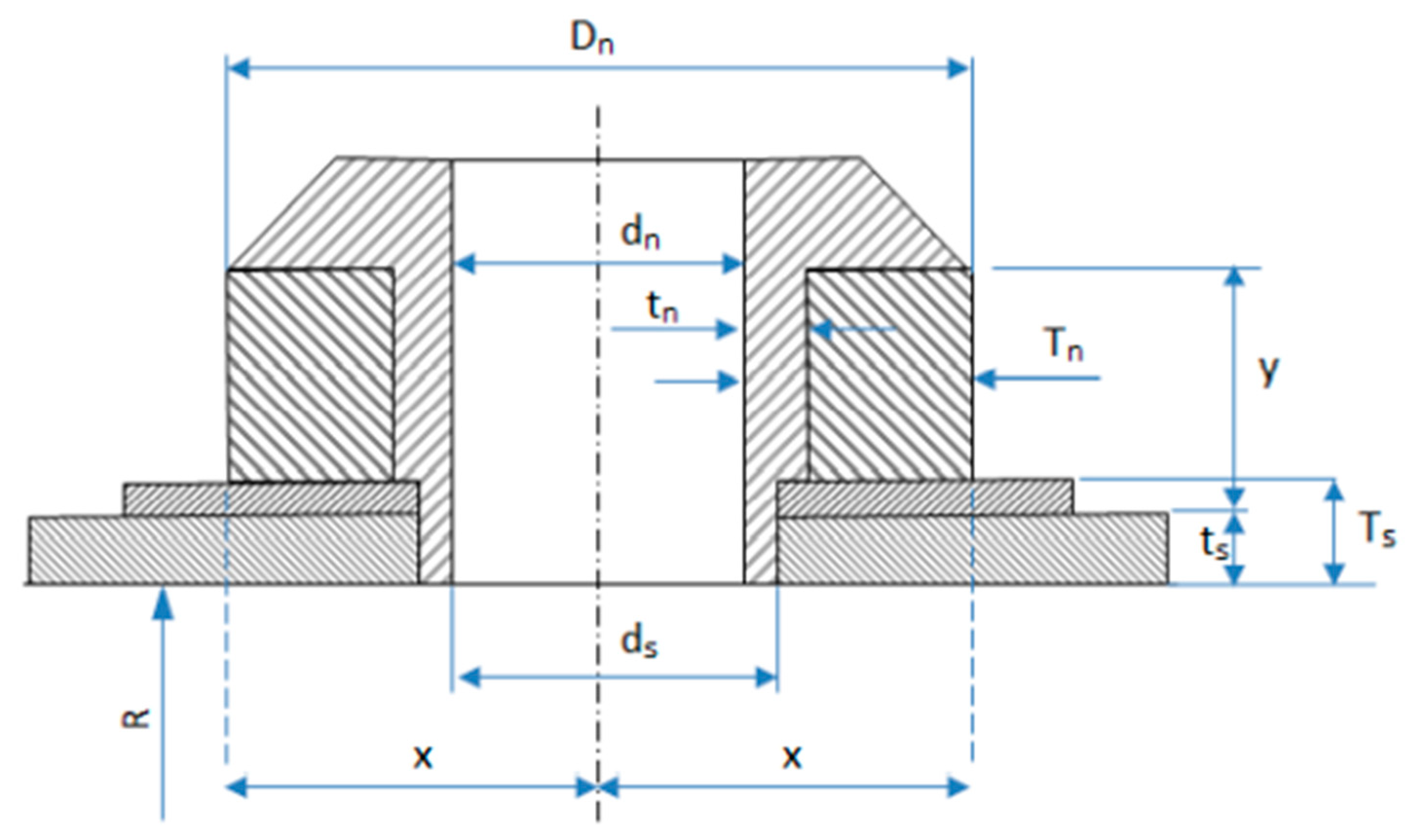
2.4. Nozzle Design
The number of nozzles should be kept to a minimum to reduce stress. Stress leads to an increased risk of failure and, therefore, an increased risk of fire, explosion, or leakage. Initially, select a 20 cm diameter nozzle with a tolerance of 12.5% and a fillet of 10 mm. To ensure the integrity of pressure vessels, it is crucial to provide adequate support for the attached nozzles, thereby minimising the risk of failure. The specific type of nozzle and its corresponding parameters can be observed in
Figure 3.
So, the external nozzle diameter is = D
n = 177.5 mm. Nozzle thickness, as shown in
Figure 3, can be calculated as below.
where:
P = Design pressure
S = Maximum allowable stress
E = Coefficient of connection of welding
R = Internal radius
Dn = External nozzle diameter
tn = Internal nozzle thickness
2.5. Nozzle Reinforcement
Various calculations can be performed to approximate the minimum thickness of material needed to support a nozzle in a pressure vessel, as follows.
Assuming corrosion allowance = 3 mm.
Assuming correction coefficient = 1.
where:
Dn = External nozzle diameter
dn = Internal nozzle diameter
ds = Diameter of nozzle on tank wall
f = correction coefficient = 1
ts = Required thickness of tank
Ts = Actual body thickness
tn = Required nozzle thickness
Tn = Actual nozzle thickness
rn = Radius of internal hole
Ar = Area of nozzle hole
As = Area of connecting region
An = Area of nozzle wall
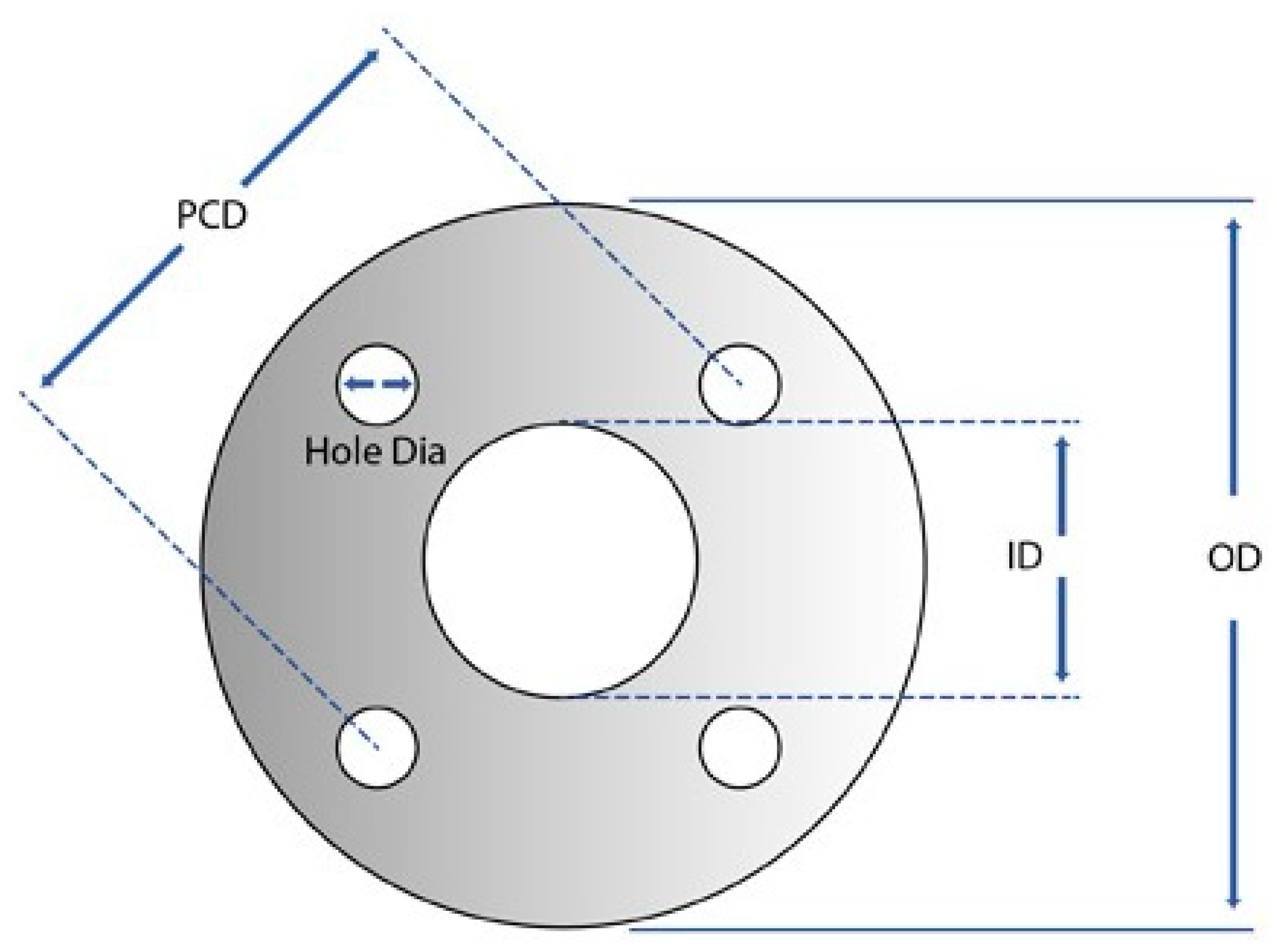
2.6. Design of Gasket
As a result, this research study design shall progress with a nozzle diameter as calculated using the ASME Code, with an internal diameter (dn) of 142.7 mm.
Assuming the internal diameter of the gasket (G
i) shall approximately match the internal diameter of the nozzle as shown in
Figure 4 and based on the instruction details in
Table 6, the gasket dimensions are as follows.
Internal diameter of the gasket (Gi) = 141 mm
External diameter of the gasket (Go) = 254 mm
Pitch circle diameter (P.C.D) = 216 mm
Number of holes = 8
Holes diameter = 22 mm
Where,
2.7. Set-Up of FE Model
The finite element (FE) analysis begins by conducting an axisymmetric analysis of a pressure vessel. The primary objective of this simulation is to identify critical areas and stress concentrations that arise due to internal pressure. Furthermore, the analysis aims to determine stress distributions in various regions of the vertical pressure vessel, which is supported by four legs. The 3D solid modelling of the pressure vessel structure was accomplished using Autodesk Inventor Professional 2023. Subsequently, finite element analysis (FEA) was performed utilizing Autodesk Inventor Nastran 2023 software [
20] The proposed dimension and design specifications for the pressure vessel analyses, which involve using the same material grades for all parts, can be found in
Table 7.
The finite element model consists of hemispherical heads, cylindrical shell, two nozzles, a manway and leg supports. To determine the optimal mesh size for accurate and efficient analysis using Inventor Nastran, a mesh sensitivity analysis was conducted. This involves creating multiple meshes with different element sizes or refinement levels and evaluating the resulting stress and deformation distributions.
To present the mesh sensitivity results, a table or plot can be included, showing key output quantities, such as von Mises stresses or displacements, obtained for different mesh densities. These results are compared to determine if further mesh refinement significantly affects the outcomes. It is important to note any convergence trends observed and explain why a particular mesh density was chosen for your analysis.
Inventor Nastran can utilise adaptive meshing capabilities, which allow the software to automatically adjust the mesh density based on the local stress gradients. By comparing the results obtained from different mesh densities, it can assess the convergence behaviour and determine the appropriate mesh size. A mesh sensitivity study investigation was completed to confirm that the stress does not depend on the mesh element number. Through careful analysis and comparison of mesh element numbers with equivalent stress in
Table 8, it was seen that there was a slight difference in stress values until an element size of 19 mm. However, after further decreasing the element size, it was found that the equivalent stress did not change. This confirms that the equivalent stress does not change value under an element size of 19 mm. Therefore, the 3D geometry model was meshed using tetrahedral mesh elements, resulting in a total of 591,292 mesh elements with an element size of 18 mm.
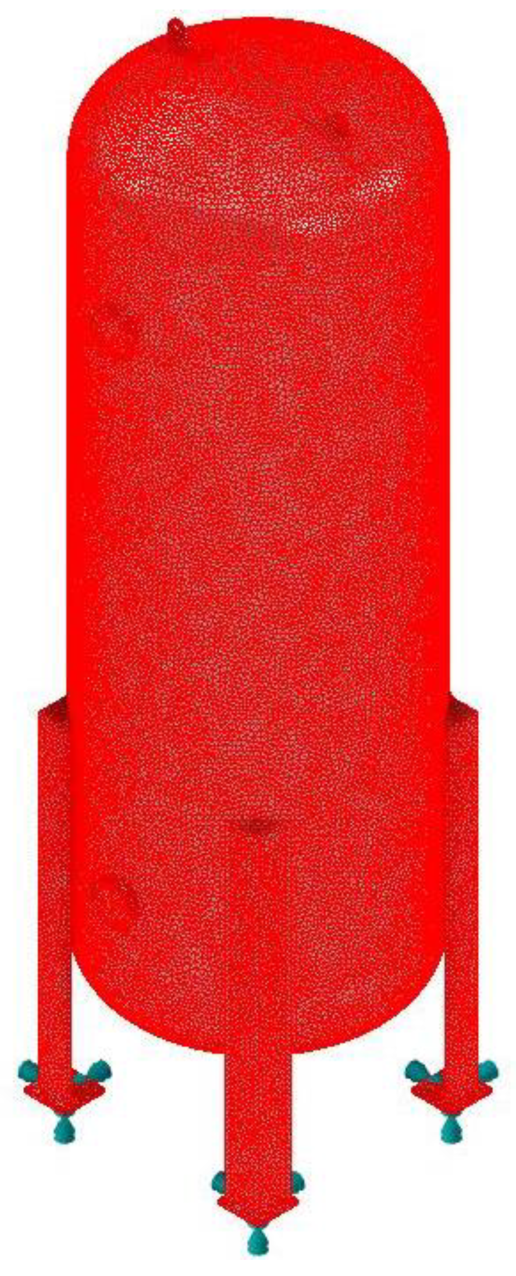
Figure 5 and
Figure 6 provide visual representations of the 3D modelling and meshing of the pressure vessel. Overall, this process ensures correct and reliable FEA analysis results.
When working with Inventor Nastran or any FEA software, it can consider several quality parameters to assess the mesh’s accuracy and reliability. Here are some commonly used parameters:
Aspect Ratio: Inventor Nastran allows you to evaluate the aspect ratio of the elements, which measures the ratio between the longest and shortest sides of an element. Ideally, elements should have aspect ratios close to 1 for better accuracy.
Skewness: Skewness quantifies the distortion of an element from its ideal shape, such as a square or a triangle. Inventor Nastran provides measures to evaluate skewness, and lower values indicate better element shapes.
Jacobian: Inventor Nastran calculates the Jacobian matrix for each element, which indicates the deformation of the element during the mapping process. Elements with Jacobians close to 1 exhibit minimal distortion.
Orthogonality: Inventor Nastran also provides tools to assess the orthogonality of element edges, which should ideally have high angles (close to 90 degrees) for regular element shapes.
Mesh Density: The density of elements should be appropriate throughout the mesh, with refined elements in critical regions and coarser elements in less critical areas. This helps capture local behaviour accurately while reducing computational costs.
These quality parameters can be examined using the mesh diagnostics or quality checking tools within Inventor Nastran. It can include a graphical representation of these metrics for your chosen mesh and discuss any steps taken to improve mesh quality if issues are identified.
Table 9 summarises the mesh quality settings and parameters.
The pressure vessel being analysed has been designed to withstand a pressure of 1.705 MPa with a consistent thickness of 14 mm throughout its structure. To ensure accurate results while optimising computation time, the model is subjected to analysis using various element sizes, carefully chosen to achieve satisfactory accuracy.
The analysis process commences with an axisymmetric examination of the pressure vessel, encompassing important components such as hemispherical heads, a cylindrical shell, two nozzles, a manway, and leg supports. The vessel is supported at the end corners as a boundary condition, while an internal pressure of 1.705 MPa is applied to the inner surface. Through this finite element model, we can precisely capture the vessel’s geometry and material properties, enabling reliable and precise analysis results.
To guarantee the structural integrity of the vessel, detailed design calculations have been completed, and meticulous drawings have been created for all of its parts. This ensures that each component is designed in accordance with the required specifications and adheres to safety standards.
Moreover,
Figure 5 and
Figure 6 depict comprehensive 3D solid models and mesh views, providing enhanced visual representations of the vertical pressure vessel. These visual aids play a vital role in facilitating the analysis process and enhancing our understanding of the vessel’s structure.
In addition to the analysis, certain additional parameters have been considered. Fixed constraints have been placed on the base of each leg, considering the downward gravitational acceleration of 9.8066 m/s2. The internal faces of the vessel have been subjected to a fixed pressure, equivalent to the design pressure of 1.705 MPa.
To simulate the weight of fluid within the vessel at 100% capacity (10,000 L), a hydrostatic pressure has been introduced. This factor allows us to account for the additional load and accurately assess the vessel’s performance under realistic conditions.
Regarding convergence, the number of iterations required to achieve convergence can vary widely depending on the complexity of the problem, the chosen numerical method, and the desired level of accuracy. Convergence is typically assessed by monitoring the residuals or errors in the simulation and comparing them to a predefined tolerance criterion.
In some cases, convergence may be achieved within a few iterations, while in others it may require thousands or even millions of iterations. The convergence behaviour can also be influenced by the choice of parameters, the quality of the initial conditions, and the stability properties of the numerical method employed.
The number of iterations required to achieve convergence in an FEA simulation using Inventor Nastran can vary depending on factors such as the complexity of the problem, the mesh quality, the convergence criteria, and the accuracy required. In this study, practically, in the simulation of a pressure vessel thickness of 14 mm, the convergence number of solution iterations reached 243. Typically, FEA simulations involve iterating through several solution cycles until convergence is achieved, with convergence determined by comparing the residual values against the specified tolerance criteria.
In conclusion, the analysis of the pressure vessel involves a comprehensive examination of its geometry, material properties, and boundary conditions. By utilising advanced finite element analysis techniques, precise design calculations and detailed drawings, we can ensure the vessel’s structural integrity and its ability to withstand the specified pressure. The inclusion of additional parameters, such as fixed constraints, internal pressure, and hydrostatic pressure, further enhances the accuracy of our analysis.
3. Discussion and Validation of Results
Autodesk Inventor Professional 2023 (Student Edition Static Structural) is an incredibly useful software tool for 3D modelling and stress analysis, which are critical steps in designing pressure vessels. By analysing the stresses and deformation caused by inner pressure, as well as the weight of the vessel and held fluid, engineers can find weaknesses in the design and gain confidence in its strengths.
This software offers a range of powerful features for stress analysis, including the ability to model the vessel in three dimensions, specify boundary conditions, and use equations to calculate total deformation and equivalent stress. By using a numerical analysis method, engineers can simulate the behaviour of the pressure vessel under different conditions, giving them the confidence to move forward with the design.
In this study, the boundary conditions include a constant pressure and a hydrostatic pressure induced by the contained fluid. These conditions are right for accurately modelling the stresses and deformation of the pressure vessel. The design pressure of 1.705 MPa, which is the total pressure of the vessel, has also been specified. This information is important for ensuring that the design meets safety standards and can withstand the intended use.
Overall, Autodesk Inventor Professional 2023 and especially Autodesk Inventor Nastran provide engineers with a powerful tool for stress analysis in pressure vessel design, helping to ensure that the resulting designs are safe, dependable, and effective.
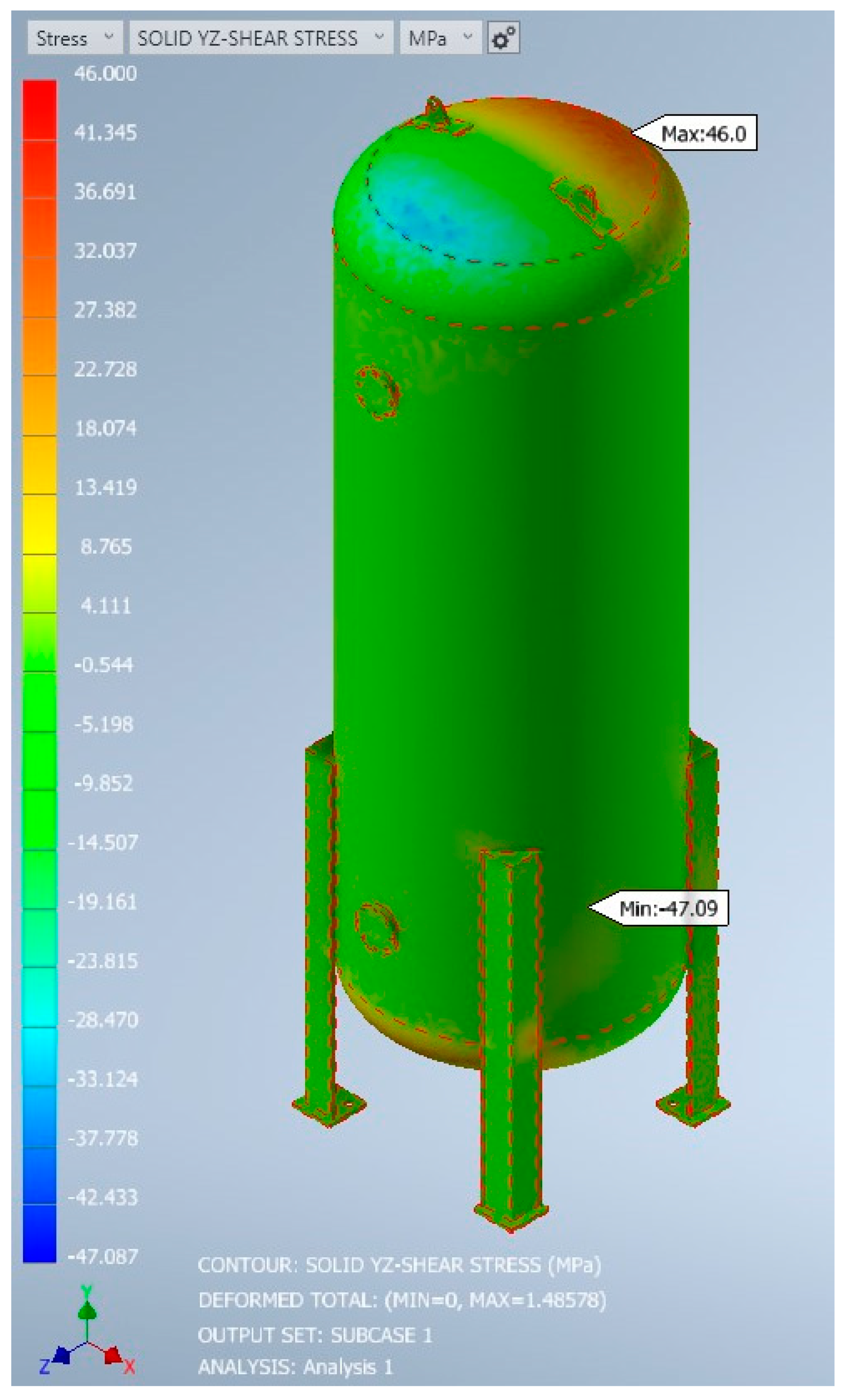
The below images show simulation results for the static structural analysis of the design. Equivalent stress (von Mises), normal and shear stress, displacement along the y-axis and displacement along the x-axis are shown in
Figure 7,
Figure 8,
Figure 9,
Figure 10 and
Figure 11, respectively. Additionally, the simulation results for their maximum values are summarised in
Table 10.
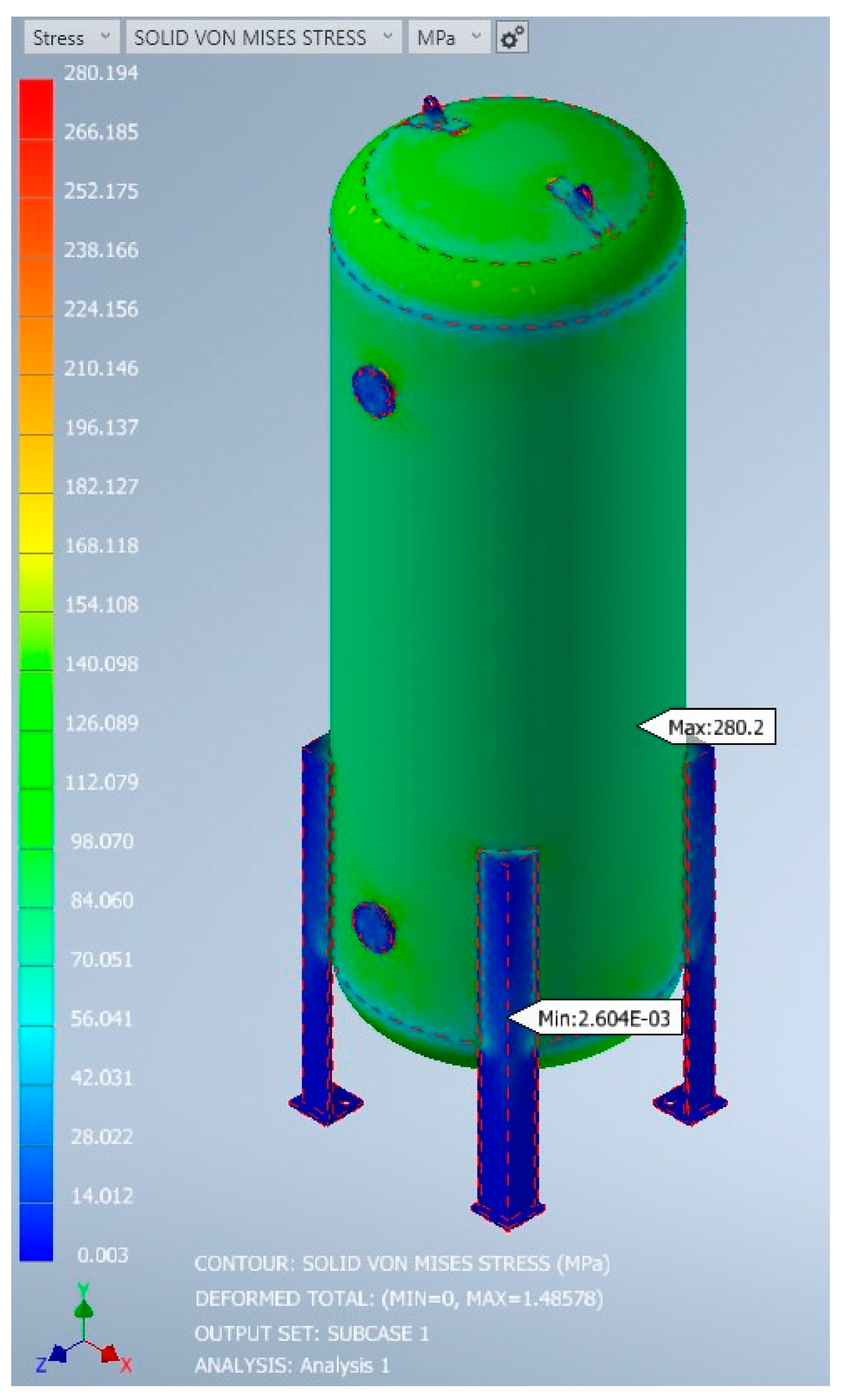
The von Mises stress in
Figure 7 provides valuable insights into the stress distribution across the pressure vessel. High-stress regions are typically observed near areas with changes in geometry, such as nozzle connections, vessel transitions, or areas of thickness variation. These regions experience increased stress levels due to the concentration of forces, or stress risers, introduced by the geometric features. It is essential to carefully evaluate these areas to ensure that the stresses remain within the allowable limits defined by relevant design codes and standards, as well as the material’s yield and ultimate strengths. If any stress concentrations exceed these limits, it may be necessary to consider design modifications or conduct further analysis to mitigate potential failure risks and ensure the vessel’s safe operation.
Additionally, the von Mises stress distribution allows for a comparison with the allowable stress criteria specific to the pressure vessel’s intended operating conditions and the selected material. This assessment ensures that the vessel can sustain the applied internal pressure without experiencing excessive plastic deformation or structural failure. It is also important to consider any cyclic loading or fatigue effects that may arise from pressure variations during the vessel’s operational life. Conducting a fatigue analysis can help identify critical locations where fatigue damage may accumulate and enable the implementation of appropriate fatigue mitigation measures, such as weld reinforcement or stress relief treatments.
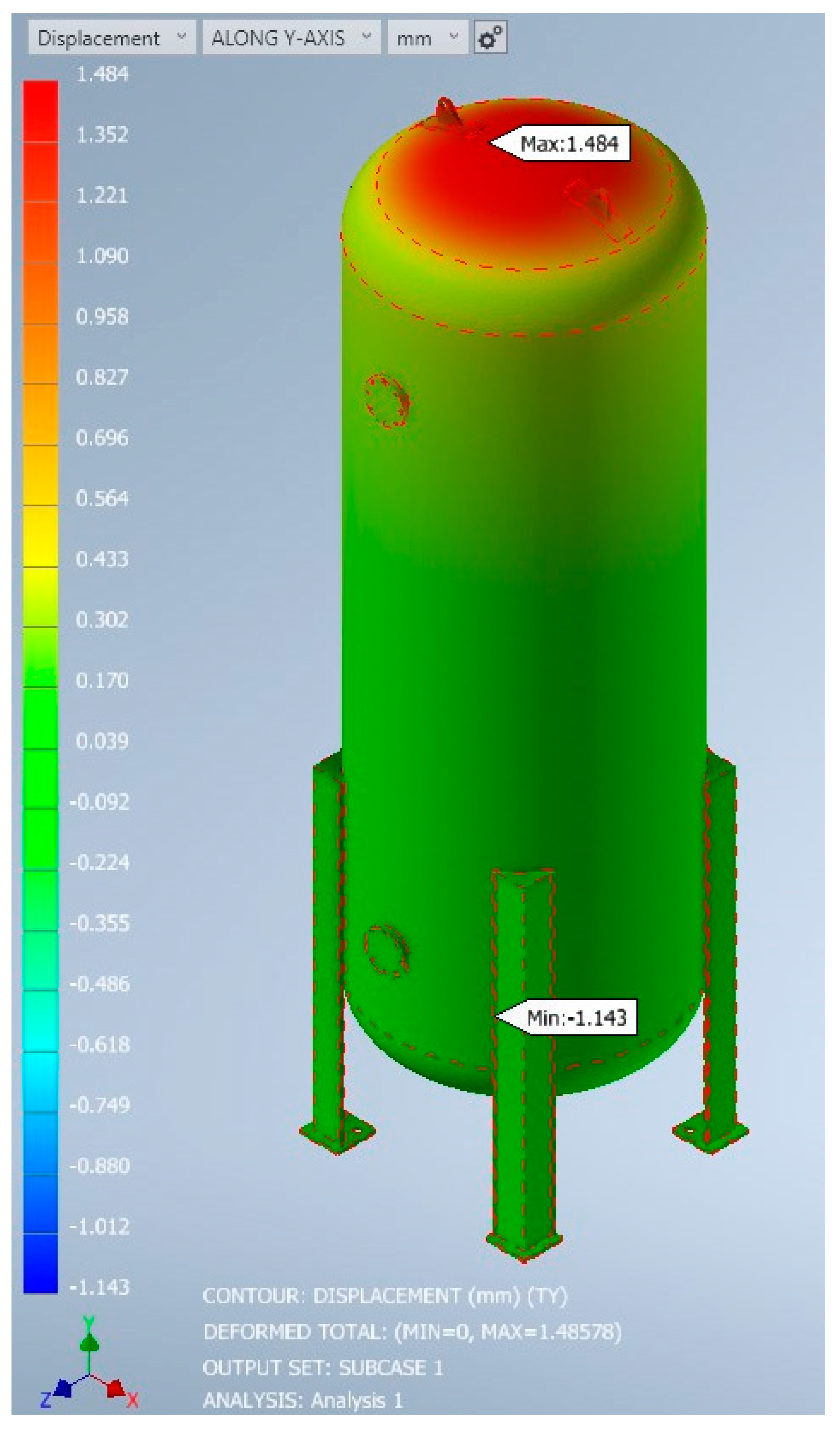
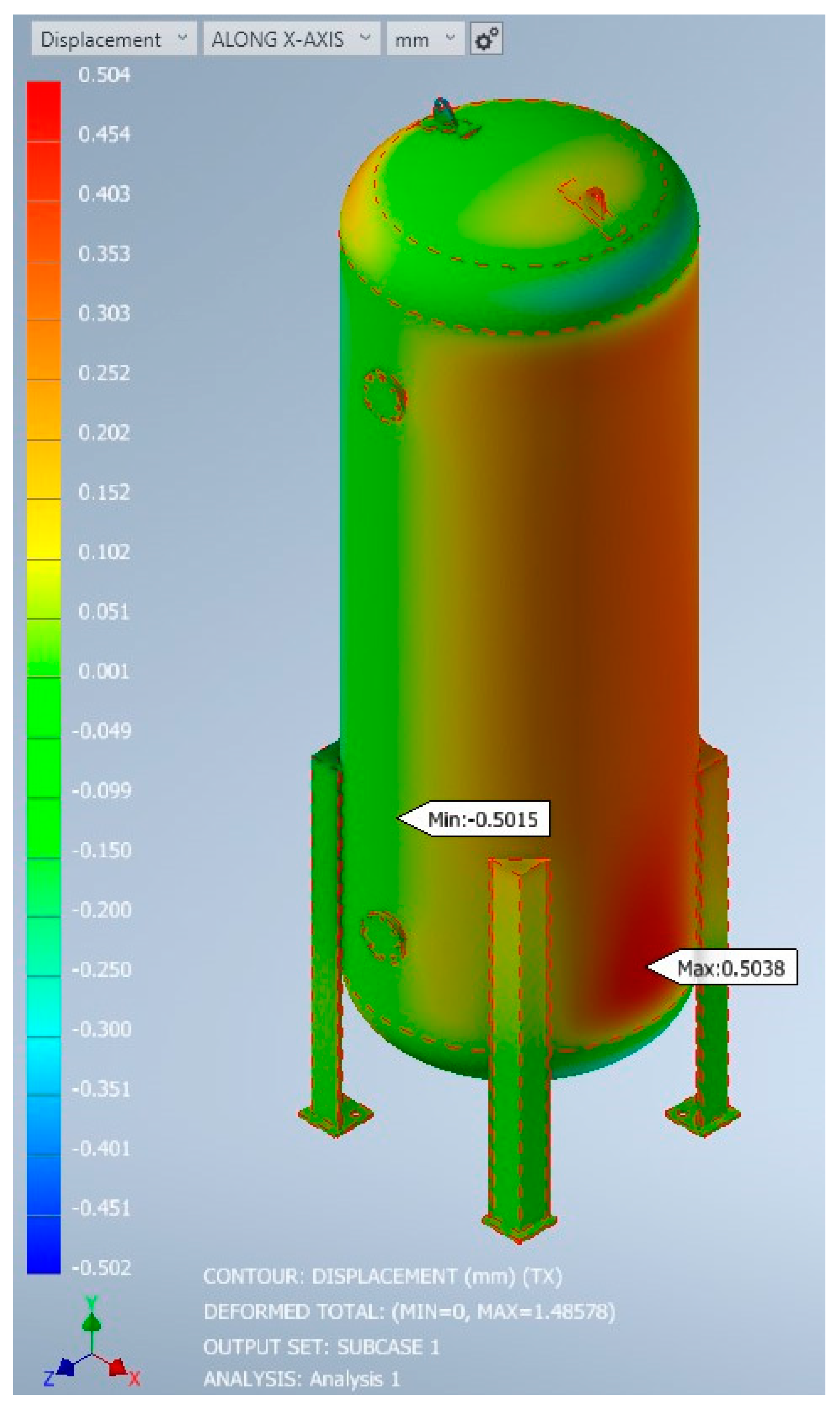
The displacements in
Figure 10 and
Figure 11 reveal the behaviour of the pressure vessel under the applied internal pressure. Overall, the vessel exhibits minimal displacement, indicating that it is designed to withstand the internal loads without excessive deformation. The displacement pattern is relatively uniform throughout the vessel, suggesting that the structure is adequately supported and the material exhibits sufficient stiffness. This uniform distribution is desirable, as it ensures the vessel maintains its shape and integrity under pressure. However, it is important to carefully examine any localised displacements or deformations observed, particularly near welds, discontinuities, or regions with geometric changes. These areas may experience stress concentrations or potential weaknesses that could compromise the structural integrity of the vessel. It is crucial to conduct a thorough investigation of these regions to assess their impact on the vessel’s performance and ensure they are within acceptable limits.
In summary, the displacement and von Mises stress analyses provide valuable information about the behaviour and integrity of a pressure vessel under internal pressure. Understanding the displacement patterns and stress distribution is crucial for ensuring that the vessel meets the necessary design requirements, can withstand the expected operational loads, and maintains its structural integrity throughout its service life. Thorough analysis and interpretation of these results are essential for making informed decisions regarding the design, fabrication, and operation of pressure vessels in various industrial applications. However, it is important to note that the specific details and analysis results will vary based on the geometry, material properties, and loading conditions of the pressure vessel being analysed.
The simulation results are positive, with most stress and strain values lying within the safe operating limits of the vessel material. There is some concern to be raised around the peak values; however, these have been investigated. The stresses and displacement values all lie within the required boundaries for material conditions. When comparing the longitudinal and hoop stress values (captured from the results using a stress probe in respective directions), the initial calculation values are close and similar. The highest equivalent stress value experienced by the pressure vessel is 42.228% different from the equivalent stress value, as shown in
Figure 7. It shows that it is lower than the maximum tensile strength of the material, which is 485 MPa.
Overall, a thorough validation of an FEA model for the design and analysis of a typical vertical pressure vessel should involve a combination of theoretical analysis and sensitivity analysis (FEA results) to ensure that the model is correct, dependable, and representative of the actual physical system. When confirming a finite element analysis (FEA) model for the design and analysis of a typical vertical pressure vessel, it is important to consider a sensitivity analysis. FEA results require a sensitivity analysis to determine the impact of changes in input parameters, such as material properties or boundary conditions, on the results of the FEA model. This can help find the most critical parameters and ensure that the FEA model is robust and dependable.
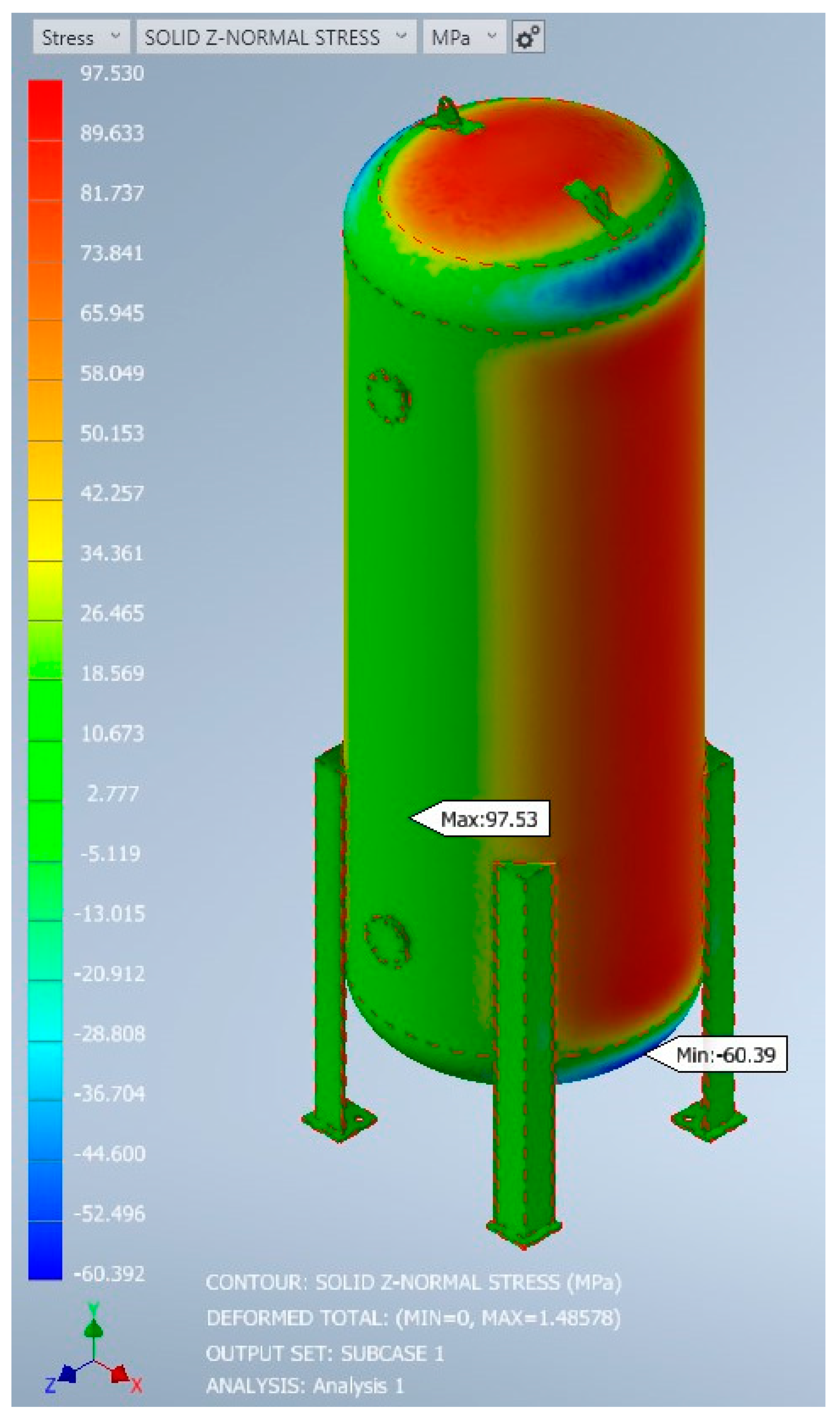
The stress components x, xy, y, z, xz, or yz in an Inventor Nastran FEA model stress analysis can be used to estimate the longitudinal and circumferential stresses in a pressure vessel, but they must be transformed into the proper coordinate system.
In general, the yz-shear stress part is aligned with the longitudinal axis of the pressure vessel, the y-stress part is aligned with the radial direction, and the z-normal stress component is aligned with the circumferential direction.
To compare the circumferential stress part from Inventor Nastran with the analytical solution, we need to find which stress part corresponds to the circumferential direction. Typically, this will be the “z-normal stress” part. Therefore, the z-normal stress part from the Inventor Nastran analysis should be compared with the circumferential stress calculated from the analytical solution.
The third principal stress is a measure of the largest shear stress in the material, and it is a key factor in finding the failure of the material under load. The longitudinal stress, on the other hand, is a type of stress that occurs in the direction of the vessel’s longitudinal axis due to the applied pressure.
Comparing the von Mises stress obtained from the FEA model results with the yield strength of the material to ensure that the pressure vessel is not overstressed is another way of validating techniques.
In addition, it will be useful to compare the deformation or displacement of the pressure vessel obtained from the analytical calculation with the deformation obtained from the FEA model results.
In summary, comparing the analytical calculations mentioned above with FEA model results is a valid technique to confirm the FEA model, but for a more comprehensive validation, it should be complemented by other validation techniques, such as comparing strain and experimental data.
The acceptable margin of error for the validation of a typical vertical pressure vessel using FEA depends on a range of factors, such as the design requirements, safety factors, and industry standards. Typically, the validation process in this study aims to ensure that the FEA results are within an acceptable range of error compared to the analytical calculation.
It is important to note that the margin of error should be evaluated in the context of the entire validation process, which may include multiple stress components, material properties, loading conditions, and other factors. Therefore, it is essential to follow established industry standards and guidelines and consult with subject matter experts to find the acceptable margin of error for a specific application.
A general guideline for the acceptable margin of error is that the FEA results should be within 5–10% of the analytical or experimental results. However, this can vary based on the specific application and industry standards. For example, some industries may require a tighter tolerance for safety-critical applications, while others may allow for a higher degree of error for non-critical applications.
Table 11 summarises the analytical and simulated results, as well as a percentage difference comparison. As can be seen in
Table 11, the stress values all lie within the required boundaries for material conditions. After comparing the longitudinal and hoop stress values obtained from the simulation using a stress probe in the respective directions, the initial calculations are within an acceptable margin of error. However, there is a significant discrepancy between the calculated and simulated results in terms of displacement along the y-axis and x-axis. The percentage difference values for these displacement results are greater than the acceptable margin of error.
One probable reason for this discrepancy is the complexity of the geometry considered in the simulation. While the first calculations may have been based on simple stress calculations for the material, the simulation considers a more complex set of factors that may be contributing to the discrepancies in the displacement results. For example, the simulation may be accounting for more intricate load patterns or other factors that were not included in the first calculations.
Despite these discrepancies, the simulation results can still be useful for finding potential issues and areas for improvement in the design. By analysing the differences between the calculated and simulated results, engineers can gain valuable insights into the behaviour of the system and make necessary adjustments to improve the design.
Overall, it is important to keep in mind the limitations of any simulation or calculation method, and to use multiple approaches to validate results and ensure the accuracy of the final design.
The finite element method was employed to determine the von Mises stress and displacement in a pressure tank containing liquefied petroleum gas (LPG) under pressure and ambient conditions. A minimum plate thickness was established based on a pressure value of 1.55 MPa. At this minimum plate thickness, the von Mises stresses were found to be below the allowable stress limit (485 MPa) for the tank material. The von Mises stress obtained from the finite element analysis was aligned with the ASME von Mises stress. The thickness and stress ranges complied with the guidelines specified in ASME Section VIII, Division 1, Part ULT.
The selected vessel material, ASTM A516 Grade 70, possesses a factor of safety of 3.5, which necessitates design considerations incorporating the material’s yield, allowable stress, and a factor of safety greater than 3.5. In this research study, multiple scenarios were examined, with each scenario treated as an individual case study due to the impact of changing boundary conditions on the results. However, the investigation did not encompass the examination of weldments along the seams of the vessel.
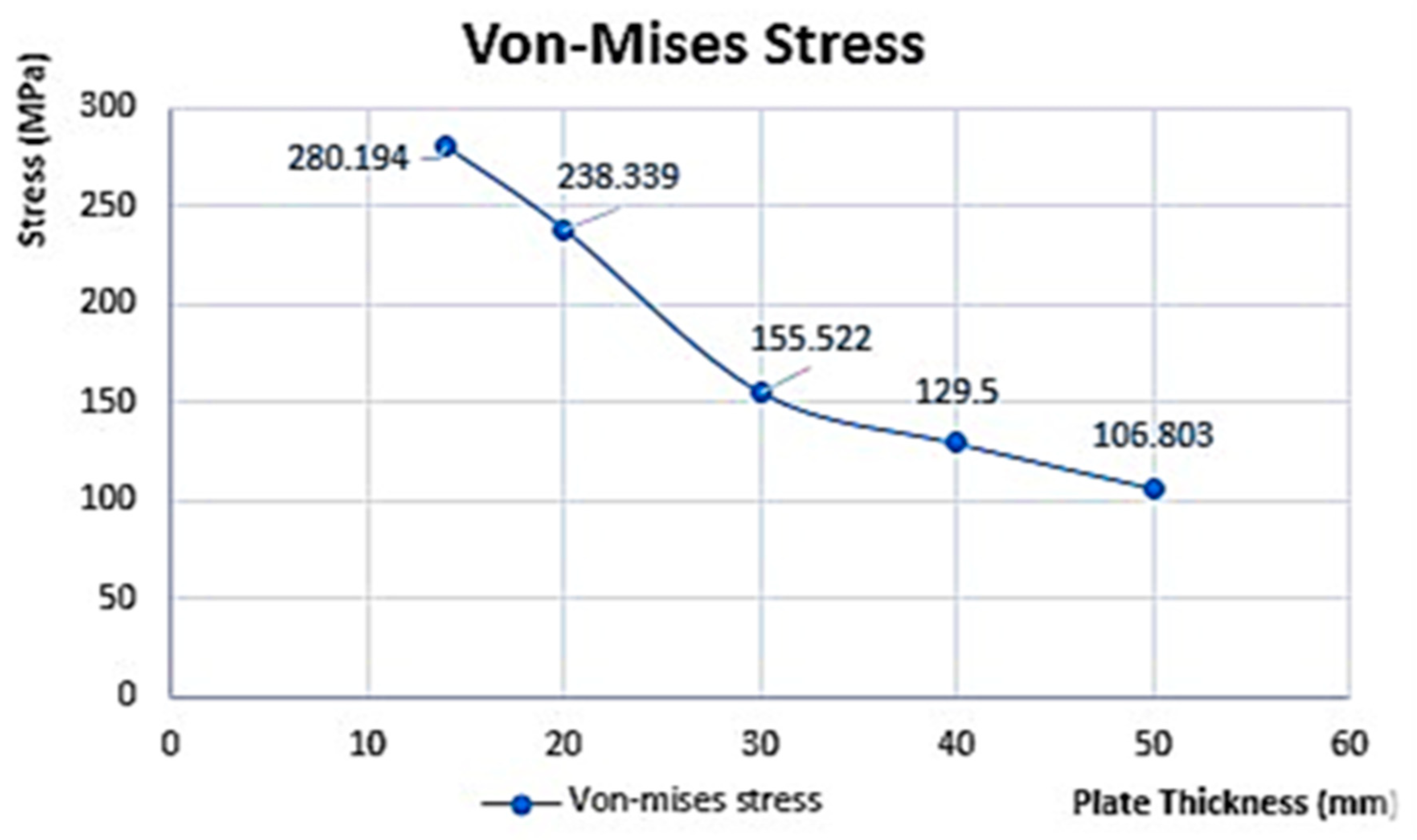
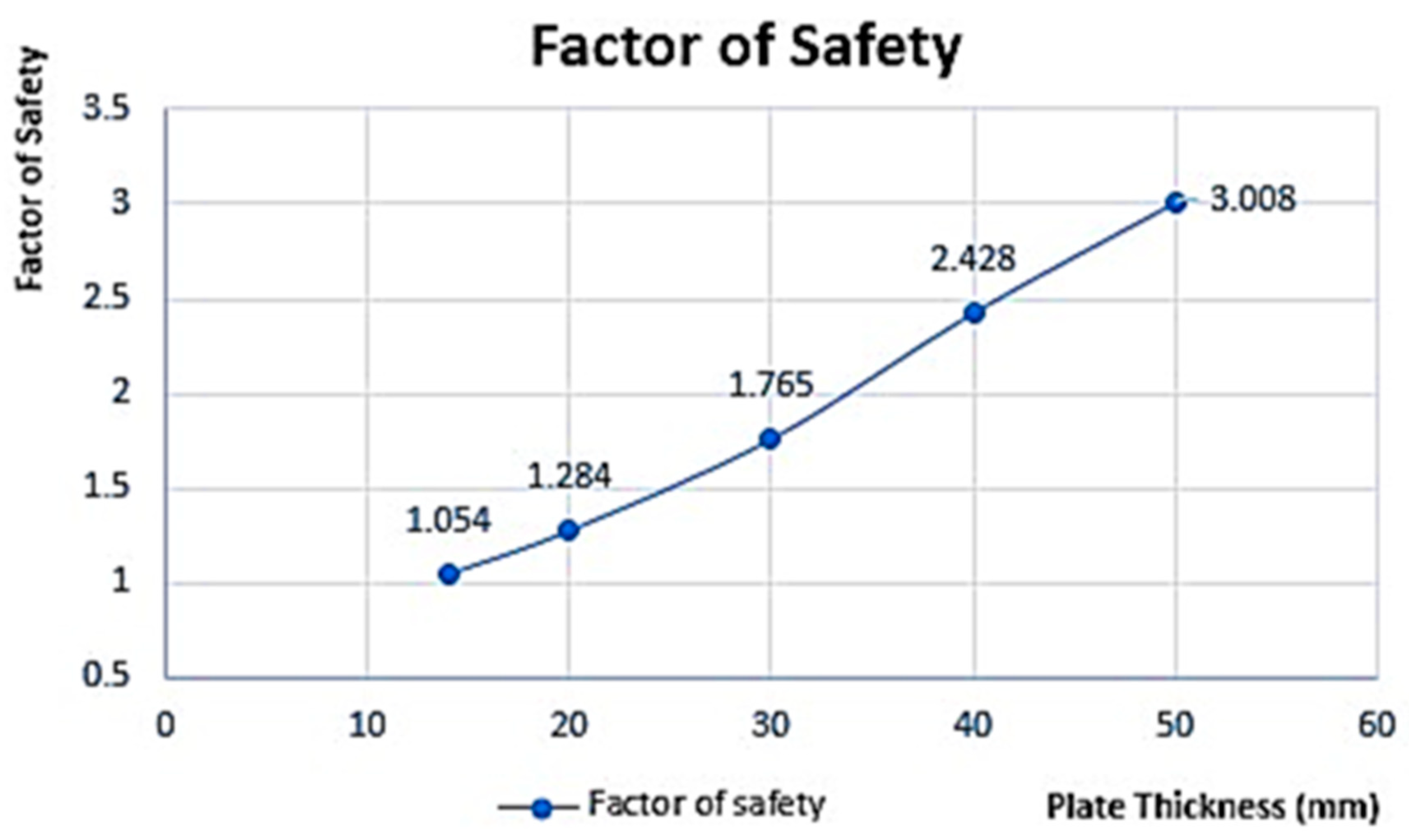
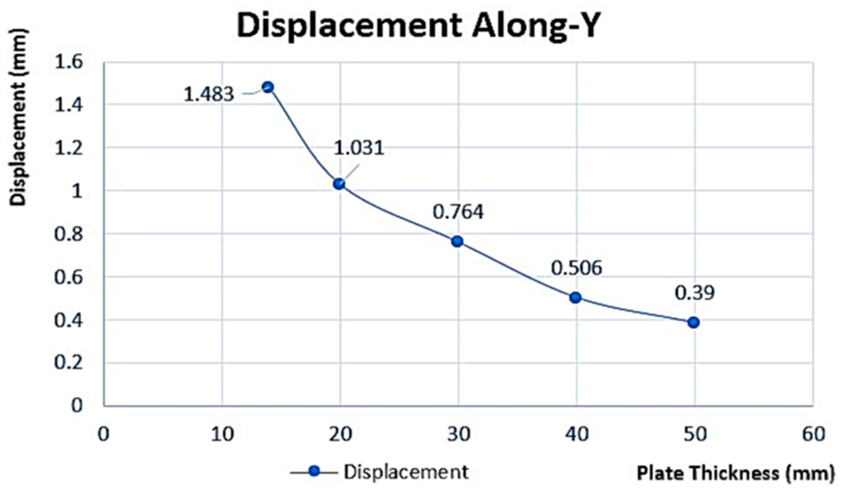
Table 12 shows a summary of von Mises’s factor of safety and displacement FEA values extracted for different plate thicknesses. These FEA values have also been represented graphically, with von Mises stress (stress developed) versus thickness shown in
Figure 12, factor of safety at different plate thicknesses in
Figure 13, and displacement along the y-axis versus plate thicknesses in
Figure 14, showing the nonlinear relationship between stress and plate thickness.
It also shows the convergence of finite element von Mises stress (stress developed) and ASME von Mises stress. The inverse relationship between thickness and stress is due to the disparity between circumferential stress (hoop stress) and plate thickness. Increasing the LPG pressure tank plate thickness decreases the displacement and von Mises stress, as presented in
Figure 12 and
Figure 14, respectively. The plate material (ASTM A516 Grade 70) of the LPG tank already has a factor of safety of 3.5.
For the range of thicknesses considered as shown in
Table 12, 14 mm thickness and below will cause catastrophic failure if the LPG pressure tank is to operate at 1.55 MPa and 60 °C, since their factor of safety is less than 3.5 (material’s factor of safety). At 50 mm thickness and above, the tank material will not yield (failure will not occur), since this range of thickness offers a factor of safety greater than 3.5. Since the vessel material is isotropic in nature, increasing plate thickness will keep the hoop stress and circumferential stress below the material yield stress; therefore, it will be twice as strong in the axial direction.
The results indicate that plate thicknesses of 14 mm and below would result in catastrophic failure if the tank operated at 1.55 MPa and 60 °C since their factor of safety is less than the material’s factor of safety (3.5). On the other hand, plate thicknesses of 50 mm and above offer a factor of safety greater than 3.5, ensuring that failure would not occur. Increasing the plate thickness helps keep the hoop stress and circumferential stress below the material yield stress, making the vessel stronger in the axial direction. However, the main drawback of increased plate thickness is the added weight of the vessel.
Overall, the summary provides an assessment of the relationship between plate thickness, stress, factor of safety, and displacement in the LPG pressure tank. It highlights the critical thickness range for safe operation and discusses the trade-off between strength and weight in the design of the vessel.
4. Conclusions
The results obtained from Autodesk Inventor Professional 2023, especially the Inventor Nastran FEA software, were in close agreement with the detailed calculations when comparing the average stress and deformation to the change in length and diameter of the pressure vessel. While the detailed calculations were valid, they only considered the cylinder’s change in length and diameter, without considering the manway, ends, nozzle, or support legs. These components have a significant impact on the overall behaviour of the pressure vessel, highlighting the importance of considering the entire system in the design process.
To achieve more correct designs for vertical pressure vessels, it is important to design each part individually. In this project, all pressure vessel components were selected based on the available ASME standards, and the manufacturers followed these standards during the manufacturing process.
The resulting stresses were found to be significantly lower than the ultimate strength of the material, which was 485 MPa. However, the highest stresses exceeded the design stress, showing that some adjustments may be necessary to ensure the safe operation of the pressure vessel.
It is worth noting that the highest deformation occurred at the manway, which is consistent with the complexity of this part. In summary, the design of a pressure vessel is an integrated system that requires a thorough understanding of the individual components, as well as their interactions with one another. By considering these factors and following industry standards, engineers can design safe and efficient pressure vessels.
The stress concentrations were seen at the contact points between the manway and the shell, showing the importance of carefully considering the design of this part. The design simulation conducted also identified stress concentration areas in the pressure vessel. These concentrated regions were observed at the connections between the tank’s bottom and the fixing base, as well as at the locations where the nozzle was attached to the tank body.
Additionally, the simulation results showed that the regions farthest away from the fixing points experienced the highest displacement values under internal pressure. This information highlights the need to carefully consider the distribution of pressure and the structural support of the pressure vessel during the design process.
In summary, the stress and displacement analysis of the pressure vessel revealed critical regions that require careful attention during the design process, such as the manway and the fixing points. By taking these factors into consideration and following industry standards, engineers can design pressure vessels that meet safety and efficiency requirements.


