Abstract
The structural feasibility of using a pultrusion of carbon-fibre-reinforced polymers (CFRP) for the lightweight design of a mast for overhead line railway electrification was investigated and simulated. Material characterisation was undertaken using three-point bending and finite element analysis to identify the orthotropic properties of the pultruded tubes designed for a composite mast for overhead electrification. An innovative design of the mast was proposed and verified using a simulation that compared the deflection and stress levels under wind and inertial load. From the simulation results, it was concluded that the proposed composite structure design complies with the mechanical performance requirements for its implementation and benefits the application with a weight reduction of more than 80% with respect to the current steel mast design.
1. Introduction
There is an increasing demand from stakeholders and consumers for a more sustainable future with lower emissions. The UK rail network needs to adopt a more proactive, cost effective, and environmentally friendly strategy whilst addressing the increasing capacity demand. Rail offers a sustainable mass transport solution with low emissions on electrified railways. They have one of the lowest emissions per passenger when compared with competing transport modes; in addition, there is also a 76% emission reduction for rail freight compared with the road alternative [1]. According to the Railway Industry Association, a battery pack storing the equivalent energy of a diesel locomotive would double the weight of the rail vehicle, and the space required to store the hydrogen in a passenger train would take up a quarter of its interior space. In the case of a freight locomotive, storing the hydrogen would take up more space than the locomotive itself [2]. Therefore, further sustainable development of the overhead line electrification (OLE) infrastructure is crucial for both practicality, efficiency, and wider environmental benefits.
Existing railway OHL infrastructure has significant pitfalls in terms of not being economical with the structural requirements produced by the heavy steel mast having a significant impact on the total cost of electrification [3]. RIA Electrification Cost Challenge 2019 highlighted that the current contribution of the OLE to the total cost can be as high as 45% due to the raw material, the installation of the structure, and the foundations [4]. Considering the Great Western Electrification Programme as reference, the cost for the OLE represents 30% of the total costs and it is also affected by operation and maintenance [3]. Further evidence in similar projects has shown that electrification can be delivered at between 33% and 50% of the costs previously predicted (£2 m and £2.5 m/STK), now at £750 k to £1 m/STK for more complex projects not expected to normally exceed £1.5 m/STK [4]. Furthermore, in terms of long-term economic benefits, electric trains are approximately 30% cheaper to maintain than a diesel train and approximately 50% cheaper than a diesel bimode train [5]. It is estimated that 32% of initial capital expenditure will be recouped over the 90-year appraisal period because of reduced operating expenditure and increased passenger revenue [1].
Structurally, the OLE must hold the wires in the required position under the dynamic load generated by the pantographs on the trains, wind forces, and the vibration from the ground. Moreover, the system must be able to withstand the thermomechanical stresses caused in the catenary generated by the high voltage, up to 10 MVA per train. Additionally, brief losses in contact by the contact wire can induce electrical arcing which can have significant effects on the longevity of the catenary system [6,7].
The components of the OLE must be able to support the catenary fixing the vertical position and allow fixing of the horizontal position by means of a registration arm. As well as this, due to the difference in the static and dynamic actions on different railway lines, the design of the OLE structure can vary in complexity and geometry; it can have a single or double cantilever, twin track cantilever, portals, head spans, and span wire portals. In all these configurations, four main loading conditions are considered:
- dead loads (equipment weight and tension),
- live loads (dynamic load from the pantographs, wind, ice, and snow),
- accidental loads (temporary situation),
- construction loads (staff working on the structure and installation equipment).
Additionally, situations are more complex in nature due to the OLE being an exposed system, which is subject to weather variables, wildlife, atmospheric pollution, and, regrettably, vandalism. The conventional design of the mast is currently based on galvanised steel or weathering steel, which is heavy and, when compared to more modern materials such as carbon-fibre-reinforced polymers, has inferior mechanical, chemical, and physical properties [8]. CFRP is exceptional in dealing with severe environmental conditions and fatigue loading [9]. The existing OLE infrastructure also implies a major carbon input at the time of manufacture; the use of zinc in the coating when smelted produces large amounts of sulphur dioxide and cadmium vapour [10].
In order to meet the mechanical properties required for the overhead line electrification (OLE) infrastructure (with objectives driven towards reductions in carbon footprint), overall weight and costs, a redesign of the initial manufacturing methods, raw material used, and method of final implantation are crucial. Pultrusion manufacturing is a highly automated continuous fibre laminating process producing high-fibre volume profiles with a constant cross-section; it is one of the most cost-effective and energy-efficient manufacturing processes to produce high strength to weight ratio profiles [11]. Numerous different applications of pultruded FRPs have been explored and implemented, from high-fatigue-resistant CFRP supports in bridge construction, to extremely high-volume fraction CFRP fibres for impact-resistant car bumpers in the automotive sector [12,13]. Although significantly more scarce, applications using pultrusion manufacturing in specific railway applications are already being investigated [14,15,16]. Juan Tang et al. investigated the structural feasibility of pultruded GFRP railway vehicle mobile panels and reported that it not only complies with the mechanical requirements for its implementation, but also implies a weight reduction of 35.5% with respect to the traditional steel panel design [17]. Each individual task demands a profile requiring a unique geometry; the shape of the final product is dictated by the shape of the cross of the dies and the shape can be circular, rectangular, square, I-shaped, or H-shaped. Fibres provide sufficient strength and stiffness along the development direction of components, whereas the polymer transfers loads between the fibres and provides a barrier against environmental attack (e.g., thermal oxidation, hygrothermal ageing, chemicals, etc.). Various polymers have been investigated in the literature; it has been found that vinyl ester resin is less vulnerable to hydrolytic reactions than polyester [18]. Epoxies have high electrical insulation and chemical resistance, and due to a low shrinkage during the curing process, has a minimal risk of residual stresses [19]. The mechanical and chemical properties required for the application dictate the selection of the most suitable geometry, matrix, and fibres systems. The replacement of traditional materials, combined with progressive optimisation on structural designs on CFRP key components, have been reported to allow the weight reduction ratio of key components to reach up to 61.1% [20].
A wide range of the literature deals with the most common failure modes of pultruded composites such as delamination, fibre breakage, matrix cracking, and buckling [21]. Pultruded parts can contain small amounts of fillers, additives, and sometimes embedded air, also known as void, that may be difficult to detect because it is not visible from the surface. Pultruded materials can also present various other challenges when it comes to direct characterisation because of their anisotropic response. The properties of a pultruded material can vary along its length and across its cross-section due to variations in fibre content, resin distribution, and processing conditions [22,23]; this makes it difficult to obtain representative samples for testing.
Numerous failure prediction models and analyses have been suggested in the literature [24,25]. Fatigue life models offer a fatigue failure criterion based on S–N curves without accounting for actual degradation mechanisms [11]. Even when modelled and tested accurately, the properties of a small coupon when tested may not accurately reflect the properties of a large structural component, typically produced in long continuous lengths, and the properties of the material can vary depending on the scale of the testing, also known as the scale effect [26,27]. Lastly, pultruded materials can be sensitive to environmental conditions such as temperature, humidity, and UV exposure which can affect their mechanical properties over time [28,29]. The literature has also highlighted environmental conditions having synergistic effects which cause combinations of degradation mechanisms which results in accelerating the damage mechanisms and time taken to occur [30], adding even further complexity to the direct characterisation of pultruded composites.
Material characterisation and numerical simulation were used to identify the material properties of the pultruded tubes used for the finite element analysis of the innovative design of the mast. This study used a steel beam type HEB 200 as a benchmark and the deflection and stress levels experienced by the proposed design were compared against it. The contributions of this study include:
- An innovative design of a pultruded composite mast design for railway overhead line structures.
- The use of a combined numerical and experimental approach to identify the material properties of pultruded profiles.
- A weight saving of around 80% of the pultruded carbon composite design compared to the steel design.
- The assessment of the stress level achieved in the composite mast using a multistep analysis which includes the preload from bolted joints.
2. Material Calibration
To perform the structural optimisation and assess the suitability of the pultruded composite profiles for the redesign of the OHL mast, the material properties to define the orthotropic properties were required. Material characterisation must include the manufacturing process, and the material selected was manufactured via pultrusion in tubing and plate shapes. It was not possible to test the tubing and plates in the transversal direction due to the curvature of the tubing and the width of the plate being much smaller than the minimum gauge length. Moreover, it was not possible to test samples under shear and so a different approach was adopted.
The approach proposed in this work was to combine mechanical testing and numerical simulation to identify the material properties. Three-point bending was performed on tubes with three different outer diameters, and force displacement response together with strain measurements were recorded during the test. The experimental values were used in combination with a finite element model (FEM), implemented in Ansys APDL, to correlate deflection and strain values with the orthotropic properties of the tubes. The optimum material properties were derived with an iterative approach where the properties were tuned to match the experimental results using as a starting value the modulus provided by the manufacturer. Tubing type, inner and outer diameter, length of each sample, and number of samples are listed in Table 1. Three different tubing’s diameters were studied; 58 mm, 54 mm, and 51 mm outer diameters with 2 mm thickness for the 58 mm and 1.5 mm thickness for 54 mm and 51 mm. For diameters of 51 mm and 58 mm, the commercially available materials HS-Carbon fibre, E-glass fibre, and Vinyl ester Resin tubing designated as Universal Carbon Tubing from Exel (Mäntyharju, Finland) were used. These tubes are manufactured using pull winding manufacturing with a reinforcement structure that includes two layers of unidirectional fibres with a layer of cross-wound glass fibres in between, a glass mat layer (75 3 w-%), and a surface layer of nonwoven material (Exelens) [31]. Additionally, tubing was procured with a 54 mm diameter designated as CXTEL Tubing, also created by pull winding manufacturing a reinforcement structure that includes two layers of unidirectional carbon fibres with a layer of cross-wound carbon fibres in between a carbon tissue layer (75 3 w-%), with the same surface finish of Exelens [32].

Table 1.
Universal Carbon Fibre and CXTEL Tubes 2018 Dimensions.
The three-point bending tests were conducted with an 8800 Series Servo hydraulic Test System equipped with a 100 kN load cell and the three-point bend test fixture from Instron (Figure 1) with a 100 mm diameter upper anvil and two 50 mm diameter lower anvils, which were adjustable to accommodate specimens of different spans.
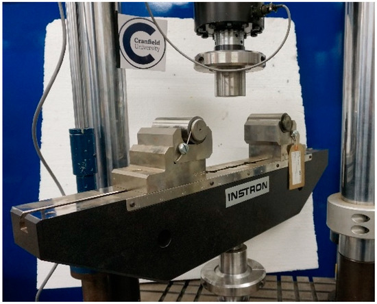
Figure 1.
Three-point bend test fixture.
The deflection of the specimen was measured through crosshead displacement and three different types of supports, one per each outer diameter. These were made of Acrylonitrile Butadiene Styrene (ABS) and manufactured using 3D printing and were used to reduce the localised contact stress between the tube and the rollers. Strain gauges with a resistance of 120 ohm from HBM were bonded onto the outer surface of each tube to measure the maximum bending strain produced on the midplane, and a National Instruments CompactDAQ running a LabVIEW 5.0 software was used for the acquisition. Load–displacement plots were obtained for each specimen and tested under displacement control (2 mm/min), and the results from the flexural tests are shown in Figure 2.
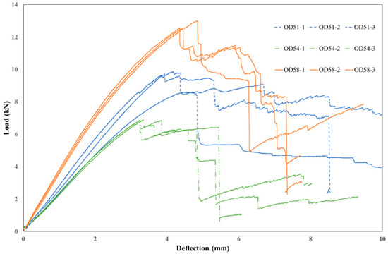
Figure 2.
Load–deflection curves from the three-point bend tests indicating the relative stiffness of each tube.
The tubing which demonstrated the highest bending stiffness (3.41 kN/mm) values was the OD58, which also had the highest average maximum load (12.6 kN), whilst the tubing which demonstrated the lowest values of bending stiffness (2.27 kN/mm) and maximum load (6.65 kN) was OD54. The tubing OD51 had an intermediate behaviour with an average bending stiffness value of 2.83 kN/mm and an average maximum load of 9.47 kN.
An image of the representative failure mode demonstrates the midplane bending moment causing transverse cracking that started in the central section and continued to propagate through the longitudinal direction until failure was experienced by the OD58 type of tubing; the specimen after failure is illustrated in Figure 3.

Figure 3.
Typical failure mode observed during the three-point bend tests (OD58-1).
The failure modes experienced by the tubes of the three different diameters were of a similar pattern to the transverse cracking that started in the central section and propagated through the longitudinal direction. The bending moment in the midplane produced elastic strain up to the point where the vertical load produced significant ovalisation of the cross-section followed by cracking through the wall of the tube.
The force deflection and strain data from the mechanical testing were used with the numerical model implemented in Ansys APDL to identify the material properties of the pultruded composite tubes. The numerical model uses shell element (shell181) for the pultruded tube and the rollers, while solid elements (Solid185) are used for the supports in 3D-printed ABS. The linear elastic material model was used for every component, with the pultruded tube modelled using orthotropic properties. The interaction between parts was accounted for by frictional contacts and a small strain large deflection assumption was used in the implementation of the simulation method. Moreover, there were two planes of loading and geometrical symmetry that allowed for the modelling of a quarter of the full model, as shown in Figure 4.
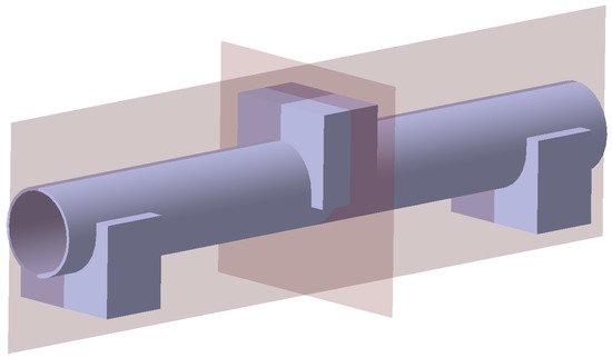
Figure 4.
Symmetry planes used for the quarter model used in Ansys.
The ranges used for the elastic modulus in the longitudinal and transverse directions to the fibre (E1, E2), the Poisson’s ratio (ν12), and the shear modulus (G12) for the three tubes (OD51, OD54, and OD58) are reported in Table 2. The Poisson’s ratio was adjusted for every configuration depending on the ratio between the longitudinal and transverse directions modulus values.

Table 2.
Ranges used for the material properties.
The values of axial strain and vertical deflection from the numerical simulations were compared to the experimental results within the elastic range up to a value of force of 6 kN. The comparison between the elastic response predicted by the numerical model and the data from the tests are shown for each tubing in Figure 5a–c. The response from the finite element model is limited to the elastic range, represented by a straight line (dashed line). The bending stress is estimated using Equation (2) with M as the internal bending moment because of the applied load P, I as the second moment of area of the circular cross-section, and D as the diameter of the tubes.
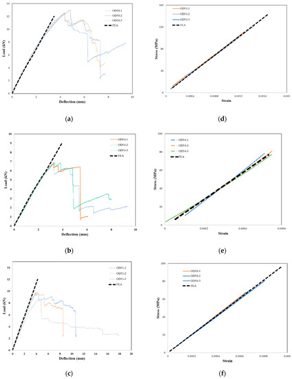
Figure 5.
Load-displacement curve from the mechanical tests and the linear elastic response from the FEA for (a) OD51, (b) OD54, and (c) OD58. Stress-strain from the mechanical testing compared with the response from simulation for (d) OD51, (e) OD54, and (f) OD58 showing the correlation in results of the mechanical testing and FEA.
The stress–strain curves in the elastic range for the OD51, OD54, and OD58 tubes are shown in Figure 5d–f with the linear response from the simulation shown as a dashed line.
The material property values obtained from the simulations and used for the stress analysis of the new mast design are reported in Table 3. The tubing has a different price depending on the fibre fraction and the type of resin as well as the use of additional layers to improve surface finish. An estimate of the cost normalised with the most expensive tubing (OD54) is also reported in Table 3.

Table 3.
Material parameter values from the numerical simulation.
The material properties reported in Table 3 have been used for the simulation of the new mast design. For the unidirectional pultruded plates adopted in the design of the mast, the properties reported in Table 4 have been assumed, since it has not been possible to perform testing on this particular material.

Table 4.
Material properties used for the unidirectional plate.
3. Numerical Model of the Current Steel Mast Design
The overhead line equipment is composed of many components used to keep the contact wire in position and ensure the continuous contact with the pantograph when the train is running on the line. When there are only one or two tracks, the contact wire is supported by a cantilever bolted onto a mast, typically made of H-section steel, on the side of the track. The catenary cable and the pull/push-off arms supporting the contact wire are attached to the ends of the cantilever. The contact wire is supported with vertical cables called droppers and suspended to the catenary (Figure 6). Where the masts and cantilevers meet, insulators are required to separate the electrically live elements. The catenary and contact wire span between the support structures that are normally spaced approximately 50 m apart [33]. The wires themselves are normally about 1500 m long and tensioned at either end. To ensure no loss of power to the pantograph, adjoining sections of wire overlap for about 180 m.
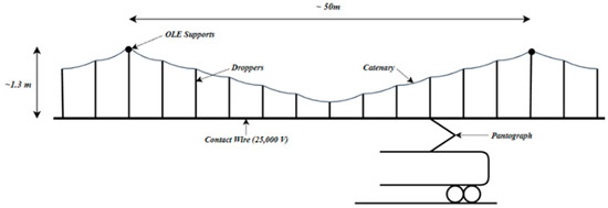
Figure 6.
OLE layout.
A schematic model of a 7.5 m steel mast with a cantilever and base plate is shown in Figure 7.
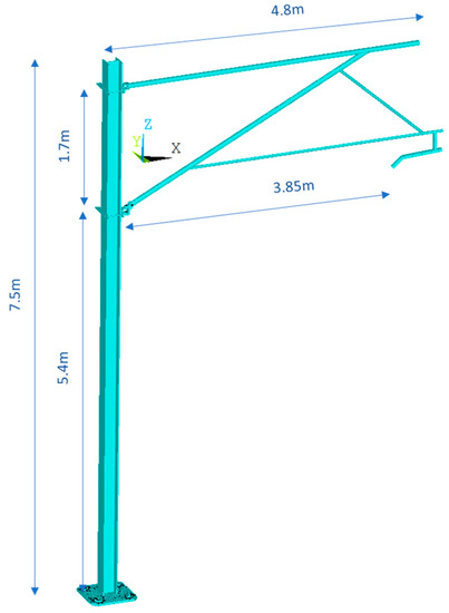
Figure 7.
3D model of the mast including the cantilever and the base plate.
The weight for the steel mast is 458.9 kg, whilst the weight for the cantilever is 150 kg. For the steel mast, considering the geometrical properties and the material constants reported in Table 5, the bending stiffness was calculated with Equation (2) assuming the mast as a cantilever beam. The bending stiffness of the mast alone is 83.44 N/mm and 29.34 N/mm considering the two symmetry planes of the HEB beam.

Table 5.
Geometrical and material properties of the current steel mast.
A new design using pultruded composite profiles has been developed considering the same geometry and material for the cantilever and redesigning the geometry of the mast to achieve the same stiffness of the steel mast. In order to guide the design, a numerical model of the steel mast has been implemented in Ansys APDL to capture the stress flow and the structural response of the mast. The numerical model (Figure 7) is composed of the steel mast, the cantilever, and the base plate. The steel mast was discretised with tetrahedral elements (solid 185) with an average dimension of 5 mm, and a linear elastic material model (Table 5) was used. The cantilever was discretised with beam elements (beam188) linked with the flanges that were bolted onto the mast (Figure 8). The articulation between the tubular profiles of the cantilever and the flanges bolted onto the mast was implemented using constraint equations that allow for a realistic degree of freedom to simulate the hinges.
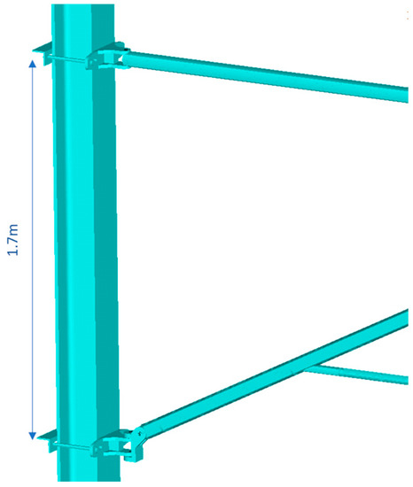
Figure 8.
Detailed view of the flanges bolted onto the steel mast.
The 30 mm thick base plate that represents the interface between the mast and the foundation pile was discretised with shell elements (shell 181) with an average dimension of 1 mm. The base plate was constrained at each slot (Figure 9a) with a rigid region using a master node in the centre of the slot that replicated the bolted joint with which the base plate was fixed onto the foundation pile (Figure 9b). The steel mast was constrained to the base plate using rigid connections to model the welded connections.
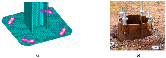
Figure 9.
Rigid connections defined to model the rigid connection to the foundation (a) and the treaded bars used on the top of the pile foundation (b).
The loading configurations used to assess the deflection and the maximum stress in the mast are the wind load (9.0 × 10⁻⁴ MPa), applied orthogonally to the surface of the mast acting in the two directions along and across the track, the vertical and lateral load corresponding to the catenary, the wire conductor, and the returning conductor (RC), as shown in Figure 10. The wind load along the track was also applied orthogonally to the plane defined by the cantilever acting in the same direction as that defined on the mast.
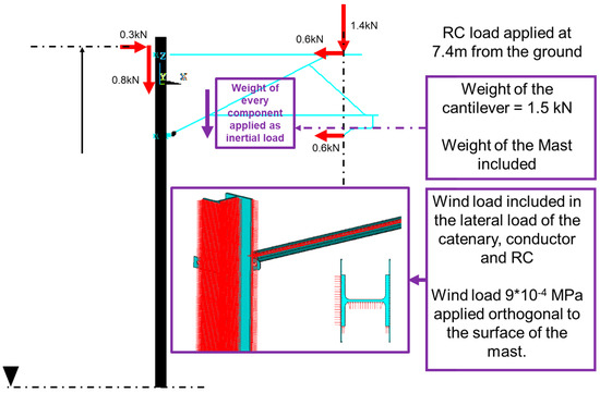
Figure 10.
Schematic view of the simplified loading configuration used for the simulations.
4. Results and Discussion of the Current Steel Mast Design
The maximum deflection in the three directions, namely vertical, across-the-track, and along-the-track, are reported in Table 6.

Table 6.
Deflection values from the simulation for the steel mast.
The resultant forces and moments measured at the based plate are reported in Table 7. The maximum principal stress (Figure 11) experienced was as expected, which was a result of the combined effect of the bending moment about the x-axis and the y-axis.

Table 7.
Reaction forces and moments at the base plate for the steel mast.
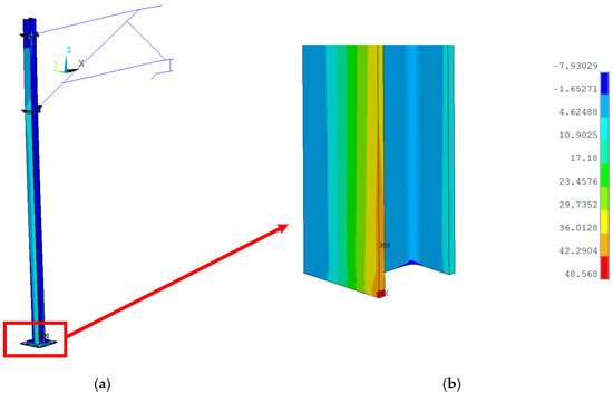
Figure 11.
Maximum principal stress in the assembly of the mast, base plate, and cantilever (a), detailed view of the maximum principal stress field at the base of the steel mast (b).
The stress induced in the mast was dominated by the bending moments, with the maximum tensile stress experienced at the base of the mast where it was welded to the base plate (Figure 11). The only section that experienced significant shear was the one between the two flanges of the cantilever, as shown in Figure 12, which was affected by the in-plane shear produced by the two horizontal forces transferred by the cantilever to the mast.
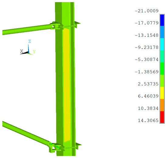
Figure 12.
Detailed view of shear stress contour plot in the mast demonstrating the maximum shear applied to the flanges of the cantilever beam.
5. Pultruded Composite Mast Design
The design of the pultruded composite solution was performed considering the target stiffness of 83.44 N/mm and 29.34 N/mm, referring to the major and minor second moment of area, respectively, and the stress distribution in the steel mast. The starting point was the envelope of the steel mast which had a cross-section of 200 × 200 mm and a length of 7.5 m. In order to meet the stiffness target, the pultruded composite tubes were spaced in the cross-section along the longitudinal direction of the mast and tangent to the external faces. This arrangement leveraged the axial stiffness of the tubes and the plates due to the unidirectional carbon fibre arrangement to withstand the bending moment produced across and along the track. The tubes were arranged as shown in the top view reported in Figure 13. Three tubes along two parallel lines in the direction along the track were equally spaced at 80 mm between the centres, and the two lines of tubes were spaced at 160 mm and placed symmetrically in respect to the centre of the composite mast. The tubes were bonded with structural adhesive to 10 mm thick unidirectional carbon fibre pultruded plates with the fibre direction of the plates aligned with the longitudinal axis of the tubes and the longitudinal axis of the mast.
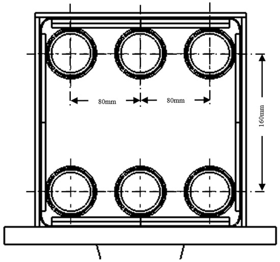
Figure 13.
Arrangement of the tubes in the cross-section.
The tubes and the unidirectional plates bonded onto the outer surface of the mast were reinforced transversally with 10 mm thick woven carbon plates spaced along the longitudinal direction of the mast at every 440 mm (Figure 14). The numerical model included the flanges and bolts used to connect the cantilever and a bonded contact was used to connect the cantilever to the mast (Figure 15).
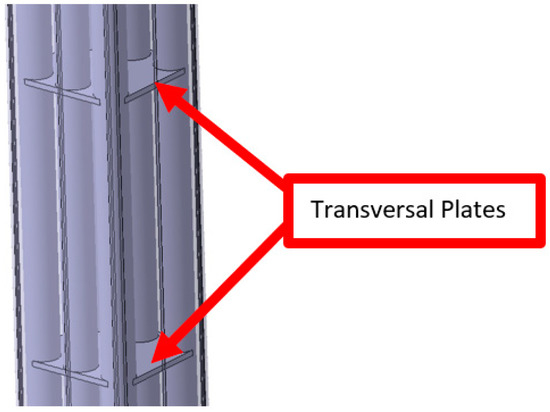
Figure 14.
Detail of the pultruded composite mast with the transversal plates.
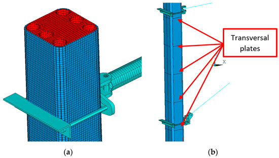
Figure 15.
Finite element model of the mast (a) with a detailed view of some of the transversal plates (b).
6. Results and Discussion of the Pultruded Composite Mast Design
The stress analysis carried out on the design of the mast using the three tubes was assessed in terms of maximum deflection of the assembly, deflection of the point in correspondence of the contact wire, and the major principal stress induced in the composite mast.
The maximum deflection values reported in Table 8 are in the global coordinate system with the Z-axis as the vertical direction, the X-axis as the across-the-track direction, and the Y-axis as the along-the-track direction. The vertical load due to the weight of the catenary and the contact wire together with the wind load are responsible for the higher deflection in the X direction. The deflection for OD54 is lower than the other two diameter tubes since the modulus is much higher: 140 GPa for OD54 compared to 82 GPa and 89 GPa for OD51 and OD58, respectively. However, the maximum difference between the three tubes is 5%, and in terms of stiffness this makes them comparable. The deflection is not only affected by the tubing but also by the unidirectional pultruded plates bonded onto the outer surfaces.

Table 8.
Deflection of the pultruded composite mast design from the simulation.
The envelope of the existing steel mast in terms of cross-section (200 × 200 mm) and length (7500 mm) was used as reference to design the composite mast. The reaction forces acting on the proposed design are reported in Table 9 for the three designs. The values of forces and moments are very close to those reported in Table 7 for the steel mast. However, the effect of the rounded corners reduces the resultant force which in turns reduces the x and y components of the reaction forces. Moreover, the weight of the composite mast design is much lower than the steel mast and this results in a reduction of the vertical load Fz.

Table 9.
Reaction forces and moments at the base plate from the simulation.
The three composite mast designs achieve a reduction in weight of 82% for the OD51, 83% for the OD54, and 81% for the OD58 compared to the weight of the steel mast (470 kg). Moreover, the deflection of the pull/push-off arms measured in correspondence with the conductor wire is 19.42 mm for the steel mast compared to 32.6 mm for the OD51, 31.2 mm for the OD54, and 32.2 mm for the OD58. The greater deflection of the three composite designs related to a lower bending stiffness of the mast; it is still within the maximum allowable deflection prescribed for the design of the mast for overhead line equipment. In particular, the NR/L2/CIV/073 “Design of overhead line structures” from Network Rail prescribes a maximum horizontal displacement across-track of the structure alone at a contact wire height of 50 mm, and a maximum horizontal displacement along-track of the structure alone at a contact wire height of 100 mm. The deflection values in Table 8 demonstrate that the current design is within these limits even if the loading conditions considered do not account for the load due to ice. However, considering that weight saving is on average 82%, there is room to increase the stiffness and reduce the deflection, which is critical in enabling stable contact between the pantograph and the contact wire.
In terms of maximum principal stress, the design with OD51 tubes reaches 238 MPa at the base plate (Figure 16), the design with OD54 tubes reaches a peak value of 139 MPa in the same region, and the design using the OD58 tubes reaches a maximum of 150 MPa at the base of the composite mast close to the base plate. However, the region of maximum stress is very localised and most of the mast is under a much lower stress level. For instance, the stress experienced by the mast designed with OD51 is below 40 MPa (Figure 16).
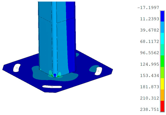
Figure 16.
Maximum principal stress in the composite mast with OD51 tubing showing the maximum stress at the base of the mast.
The region between the flanges of the cantilever undergoes shear stress in the panels aligned with the across-the-track direction, whilst the panels aligned along the track experience tensile and compressive stress due to the bending moment produced by the wind and inertial loads. In Figure 17, the vectorial plot of the principal stresses in one of the two panels aligned to the across-the-track direction are shown. Due to the bending moment across the track, the principal stresses are oriented at ±45° closer to the midplane, whilst the tensile and compressive stresses tend to align to the vertical direction further from the midplane.
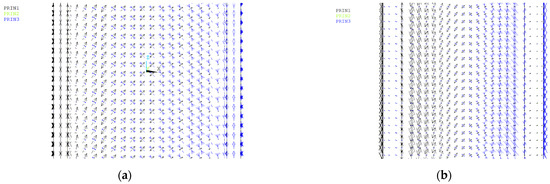
Figure 17.
Vectorial plot of the principal stress in the panel aligned to the across-the-track direction showing the steel mast (a) and composite mast (b) in the region between the flanges of the cantilever beam.
The transversal plates experience an in-plane stress dominated by shear stress due to the load transfer between the external plates and the tubes. The vectorial plot of the principal stresses shown in Figure 18a demonstrates that the highest biaxial stress is around the tubes, with the part of the plate closer to the midplane experiencing almost no stress. A change is noticed in correspondence with the flanges of the cantilever (Figure 18b), where the minor principal stress is dominant and shows a stress flow dominated by compressive stresses to the localised action of the flanges transferring the load to the composite mast.
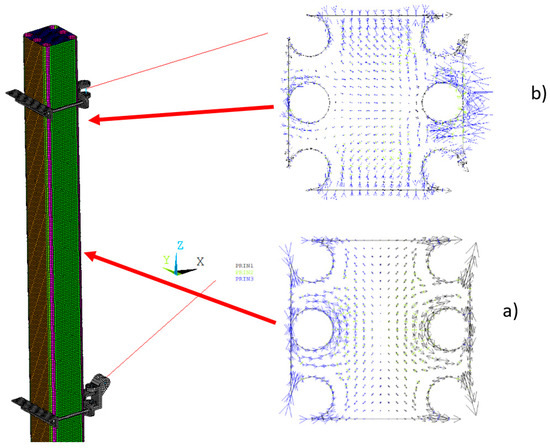
Figure 18.
Vectorial plot of the principal stress in the transversal plate (a) close to the flange and (b) in between the two flanges.
The minor principal stress field induced by a preload of 60 kN applied to the four bolts of the top and bottom flange was calculated using the same model implemented for the static structural analysis without the other external loads. The contour plot of the minor principal stress is shown in Figure 19, where it can be assessed that the effect of the preload is localised to the section of the mast in contact with the flanges, and the maximum stress value is around 80 MPa, well below the strength of the composite plates and tubes. The compressive stress produced by the preload from the bolts is used to initialise the model before the external loading is applied so that the maximum stress accounts for it.
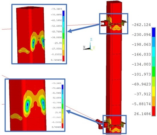
Figure 19.
Minor principal stress induced by the preload of the bolts showing regions of high stress concentrations.
7. Conclusions
The pultruded composite structure design proposed as an alternative to the steel mast currently adopted not only complies with the mechanical requirements for its implementation, but also implies a weight reduction of more than 80% with respect to the original steel design. The simulations implemented in Ansys APDL were used to complement data from three-point bend testing to identify the material properties of the tubing used for the lighter design. Moreover, numerical simulation of the full structure including mast, cantilever, and base plate was used to prove that the weight of the mast can be significantly reduced whilst still remaining within the deflection limits prescribed by the standard, and with stress values comparable to those experienced by the steel mast and well below the admissible stress values for the material of the tubing and the unidirectional plates. The stress flow experienced by the composite mast was discussed, confirming that the transversal plates experienced mainly shear stress, whilst the external plates experienced uniaxial stress flow due to the overturning bending moment. Moreover, the transversal plates close to the flanges used to bolt the cantilever onto the mast experienced uniaxial compression due to the local load transfer, confirming the expected behaviour. These results demonstrate that pultruded composite OHL masts are an excellent method for achieving sustainable rail electrification.
The commercial case for electrification of rail networks has, in the past, been compromised by the high up-front cost of wiring. The composite mast option holds out the real prospect of reducing this barrier significantly. It will also allow the more rapid installation of the electrification equipment as the masts are lighter and easier to deliver to site. This will minimise the impact caused by the transition to electrification by reducing the need for track and route occupation as this work is undertaken. It will also allow the delivery of rail electrified services with all their associated benefits to be much quicker. These are cardinal advantages that reinforce the commercial case for widespread electrification and the use of the new masts.
The composite masts will also reduce the associated carbon impact during manufacture and installation. Mast foundations will be less complex and less deep, allowing projects to be delivered in shorter time frames. The composite masts will also last longer in service than their metal equivalent and are capable of withstanding extreme climatic conditions.
The composite masts are an innovative and credible means to an end by making rail services, both passenger and freight, more attractive, competitive, and cost-effective as well as contributing to long-term emission reductions.
8. Declaration of Competing Interest
The authors declare that they have no known competing financial interests or personal relationships that could have appeared to influence the work reported in this paper.
Author Contributions
Conceptualization, M.G., M.R. and P.M.; methodology, M.G. and M.R.; validation, B.C.; investigation, M.G.; resources, M.G. and P.M.; writing—original draft, B.C.; writing—review and editing, M.G., M.R., P.M. and J.B.; supervision, M.G.; funding acquisition, M.G. All authors have read and agreed to the published version of the manuscript.
Funding
This work was carried out as part of the project “Innovative MAst for Greener Electrification” (IMAGE) Application Number: 10002551 funded by the Department for Transport and Innovate UK and led by Furrer + Frey.
Data Availability Statement
Data will be made available on request.
Acknowledgments
The authors would also like to acknowledge the support from Prodrive in the preparation of the samples used for the three-point bend testing.
Conflicts of Interest
The authors declare no conflict of interest.
References
- Rail, N. Traction Decarbonisation Network Strategy, Interim Programme Business Case. Network Rail. Available online: https://www.networkrail.co.uk/wpcontent/uploads/2020/09/Traction-Decarbonisation-Network-Strategy-Interim-Programme-Business-Case.pdf (accessed on 12 May 2023).
- Kent, S.; Iwnicki, S.; Houghton, T. Options for Traction Energy Decarbonisation in Rail: Options Evaluation. SPARK Report, 2019. Available online: https://www.sparkrail.org/Lists/Records/DispForm.aspx?ID=26141 (accessed on 12 May 2023).
- Higgins, R.; Watkins, S.; Saville, D.; Higgins, N.R.; Bussell, S.; Jones, D. Great Western Main Line Electrification-Cardiff to Swansea—Outline Business Case. 2012. Available online: https://www.gov.wales/sites/default/files/publications/2017-10/great-western-main-line-electrification-cardiff-to-swansea-outline-business-case.pdf (accessed on 3 June 2023).
- RIA Electrification Cost Challenge. London, March 2019. Available online: www.riagb.org.uk (accessed on 14 May 2023).
- Written Evidence Submitted by the Campaign to Electrify Britain’s Railway (TFF0012). April 2019. Available online: https://committees.parliament.uk/writtenevidence/103103/html/ (accessed on 13 May 2023).
- Sunar. Arc Damage Identification and Its Effects on Fatigue Life of Contact Wires in Railway Overhead Lines Arc Damage Identification and Its Effects on Fatigue Life of Contact Wires in Railway Overhead Lines View Project. Available online: https://www.researchgate.net/publication/351326945 (accessed on 13 May 2023).
- Gao, G.; Zhang, T.; Wei, W.; Hu, Y.; Wu, G.; Zhou, N. A pantograph arcing model for electrified railways with different speeds. Proc. Inst. Mech. Eng. Part F J. Rail Rapid Transit 2017, 232, 1731–1740. [Google Scholar] [CrossRef]
- Deokar, S. A Review Paper on Properties of Carbon Fiber Reinforced Polymers. 2016. Available online: www.ijirst.org (accessed on 13 May 2023).
- Alam, P.; Mamalis, D.; Robert, C.; Floreani, C.; Brádaigh, C.M. The fatigue of carbon fibre reinforced plastics—A review. Compos. Part B Eng. 2019, 166, 555–579. [Google Scholar] [CrossRef]
- Zhang, X.; Yang, L.; Li, Y.; Li, H.; Wang, W.; Ye, B. Impacts of lead/zinc mining and smelting on the environment and human health in China. Environ. Monit. Assess. 2011, 184, 2261–2273. [Google Scholar] [CrossRef] [PubMed]
- Vedernikov, A.; Safonov, A.; Tucci, F.; Carlone, P.; Akhatov, I. Pultruded materials and structures: A review. J. Compos. Mater. 2020, 54, 4081–4117. [Google Scholar] [CrossRef]
- Wazeer, A.; Das, A.; Abeykoon, C.; Sinha, A.; Karmakar, A. Composites for Electric Vehicles and Automotive Sector: A Review. Green Energy Intell. Transp. 2022, 100043. [Google Scholar] [CrossRef]
- Qureshi, J. A Review of Fibre Reinforced Polymer Bridges. Fibers 2023, 11, 40. [Google Scholar] [CrossRef]
- Jiang, J.; Zhang, Z.; Fu, J.; Ramakrishnan, K.R.; Wang, C.; Wang, H. Impact damage behavior of lightweight CFRP protection suspender on railway vehicles. Mater. Des. 2021, 213, 110332. [Google Scholar] [CrossRef]
- Tian, A.; Cui, J. Performance of modified epoxy resin for carbonfiber composite pultruded profiles. Hecheng Shuzhi Ji Suliao/China Synth. Resin Plast. 2021, 38, 27–30. [Google Scholar] [CrossRef]
- Johnston, J.; Mirza, O.; Kemp, M.; Gates, T. Flexural behaviour of alternate transom using composite fibre pultruded sections. Eng. Fail. Anal. 2018, 94, 47–68. [Google Scholar] [CrossRef]
- Tang, J.; Zhou, Z.; Chen, H.; Wang, S.; Gutiérrez, A. Research on the lightweight design of GFRP fabric pultrusion panels for railway vehicle. Compos. Struct. 2022, 286, 115221. [Google Scholar] [CrossRef]
- Visco, A.; Campo, N.; Cianciafara, P. Comparison of seawater absorption properties of thermoset resins based composites. Compos. Part A Appl. Sci. Manuf. 2010, 42, 123–130. [Google Scholar] [CrossRef]
- Gibson, G. Epoxy resins. In Brydson’s Plastics Materials; Elsevier: Amsterdam, The Netherlands, 2017; pp. 773–797. [Google Scholar]
- Chen, Y.; Yuan, M.; Wang, H.; Yu, R.; Hua, L. Progressive optimization on structural design and weight reduction of CFRP key components. Int. J. Light. Mater. Manuf. 2023, 6, 59–71. [Google Scholar] [CrossRef]
- Thomsen, O.T.; Kratmann, K. Experimental Characterisation of Parameters Controlling the Compressive Failure of Pultruded Unidirectional Carbon Fibre Composites. Appl. Mech. Mater. 2010, 24–25, 15–22. [Google Scholar] [CrossRef]
- Vedernikov, A.; Gemi, L.; Madenci, E.; Özkılıç, Y.O.; Yazman, Ş.; Gusev, S.; Sulimov, A.; Bondareva, J.; Evlashin, S.; Konev, S.; et al. Effects of high pulling speeds on mechanical properties and morphology of pultruded GFRP composite flat laminates. Compos. Struct. 2022, 301, 116216. [Google Scholar] [CrossRef]
- Boukhili, R.; Boukehili, H.; Ben Daly, H.; Gasmi, A. Physical and mechanical properties of pultruded composites containing fillers and low profile additives. Polym. Compos. 2005, 27, 71–81. [Google Scholar] [CrossRef]
- Jiang, W.; Zhang, Q.; Zhang, Y.; Guo, Z.; Tu, S.-T. Flexural behavior and damage evolution of pultruded fibre-reinforced composite by acoustic emission test and a new progressive damage model. Int. J. Mech. Sci. 2020, 188, 105955. [Google Scholar] [CrossRef]
- Kilic, H.; Haj-Ali, R. Progressive damage and nonlinear analysis of pultruded composite structures. Compos. Part B Eng. 2003, 34, 235–250. [Google Scholar] [CrossRef]
- Minchenkov, K.; Vedernikov, A.; Safonov, A.; Akhatov, I. Thermoplastic Pultrusion: A Review. Polymers 2021, 13, 180. [Google Scholar] [CrossRef]
- Almir, B.S.; Santos, N.; Lebre, C.L. Flexural Stiffness Characterization of Fiber Reinforced Plastic (FRP) Postured Beams. Compos. Struct. 2007, 81, 274–282. [Google Scholar]
- Kepir, Y.; Gunoz, A.; Memduh, K. Effects of environmental conditions on the mechanical properties of composite materials. Adv. Eng. J. 2021, 1, 21–25. [Google Scholar]
- Liu, T.; Liu, X.; Feng, P. A comprehensive review on mechanical properties of pultruded FRP composites subjected to long-term environmental effects. Compos. Part B Eng. 2020, 191, 107958. [Google Scholar] [CrossRef]
- Kumar, B.G.; Singh, R.A.P.; Nakamura, T. Degradation of Carbon Fiber-Reinforced Epoxy Composites by Ultraviolet Radiation and Condensation. J. Compos. Mater. 2002, 36, 2713–2733. [Google Scholar] [CrossRef]
- Exel Composites. Product Specification Universal CF Tubes; Exel Composites: Mäkituvantie, Finland, 2018. [Google Scholar]
- Exel Composites. Product Specification CXTEL Tubes; Exel Composites: Mäkituvantie, Finland, 2018. [Google Scholar]
- Baker, C.; Johnson, T.; Flynn, D.; Hemida, H.; Quinn, A.; Soper, D.; Sterling, M. (Eds.) Butterworth-Heinemann Chapter 10—Aerodynamic effects on pantographs and overhead wire systems. In Train Aerodynamics; Butterworth-Heinemann: Oxford, UK, 2019; pp. 201–227. [Google Scholar] [CrossRef]
Disclaimer/Publisher’s Note: The statements, opinions and data contained in all publications are solely those of the individual author(s) and contributor(s) and not of MDPI and/or the editor(s). MDPI and/or the editor(s) disclaim responsibility for any injury to people or property resulting from any ideas, methods, instructions or products referred to in the content. |
© 2023 by the authors. Licensee MDPI, Basel, Switzerland. This article is an open access article distributed under the terms and conditions of the Creative Commons Attribution (CC BY) license (https://creativecommons.org/licenses/by/4.0/).