Article

Reliability Analysis of Steel Bridge Girders Strengthened with CFRP Considering the Debonding of Adhesive Layer

Faculty of Road and Bridge Engineering, The University of Danang–University of Science and Technology, 54 Nguyen Luong Bang Str., Danang 550000, Vietnam
*
Author to whom correspondence should be addressed.
Designs 2022, 6(6), 126; https://doi.org/10.3390/designs6060126
Submission received: 23 November 2022 / Revised: 12 December 2022 / Accepted: 14 December 2022 / Published: 15 December 2022
(This article belongs to the Section Civil Engineering Design)

Abstract

:
One issue to consider while designing and constructing steel girders reinforced with carbon fiber-reinforced polymer (CFRP) plates in bridges is debonding failure. Previous studies showed that the parameters such as characteristics of material, load, adhesive, and CFRP plates have an effect on the failure probability of steel girder, which is represented by the reliability index. Therefore, this study analyzes the reliability indices of steel girders in bridges strengthened with CFRP plates to clarify the effects of debonding failure. Debonding and strength limit states are used to compare differences in reliability indices of different design scenarios. Strength and debonding margin the functions for the strength limit state and debonding limit state will be established in this study. The probability of failure is determined by a Monte Carlo simulation (MCS). It is found that the reliability index of debonding limit state is much lower than that of the strength limit state. This shows that the debonding failure should be considered significant in the reliability analysis of steel bridge girders strengthened with CFRP plate.

1. Introduction

An increasing number of bridges are being rehabilitated using Carbon Fiber Reinforced Polymers (CFRP), which also extends their lifetime [1,2]. The primary benefits of utilizing CFRP plates are the project’s overall cost savings, high strength, lightweight construction, and longevity [3]. As a direct result of this, a significant amount of work [4,5,6,7,8,9,10,11,12,13,14,15,16] has been carried out to evaluate the potential applications of carbon fiber-reinforced plastic (CFRP) in repairing, recovering, and reinforcing steel girders. Currently, the properties of these plates have been significantly improved, especially since the CFRP elasticity-modulus is approximately twice as high as that of structural steel. Additionally, the stiffness can be increased dramatically by using various dimensions and strengths [17]. The debonding of the CFRP plate ends regarded as a significant failure mode, and its occurrence should be prevented in order to avoid an unwanted failure of the system. The debonding strength of steel beams reinforced with CFRP plates has already been studied in a number of studies [18,19]. Therefore, one of the most important things for the design of CFRP-reinforced steel bridge girders is to consider the bonding between CFRP, adhesive, and steel surfaces. In general, the adhesive layer features substantially impact debonding occurrence. In the research carried out by Stratford and Cadei [20], a computation was made to determine the maximum stress occurring in the adhesive layer at the point where the specimens failed. When debonding occurs suddenly, CFRP-strengthened steel girders lose their stiffness and strength capacity. In fact, debonding is one of the most common failure mechanisms relating to steel bridge girders strengthened with CFRP plates. This occurs as a result of the fact that the CFRP plate does not entirely adhere well to the steel bridge girder. Meng Liu and Mina Dawood conducted a reliability analysis for steel beams reinforced with CFRP plate, considering the debonding [21]. In this study, based on the analytical formulas most frequently used in design recommendations, the experimental database was utilized to evaluate the modeling uncertainty for debonding failures [21]. In addition, the Monte Carlo method was selected as the method of choice for computing the resistance factors that were necessary to accomplish the goal of achieving a reliability index of 3.5 over a number of different design scenarios. The debonding of the CFRP was deemed to be a failure that caused the limit state [21]. Delbariani-Nejad et al. examined the deboning behavior of metal-composite adhesive junctions. For the purpose of determining the debonding growth, this study utilized the Monte Carlo approach, as well as the first-order and second-moment reliability methodologies. The influence of initial debonding length on debonding growth across all modes is explored. The random variables comprising the initial debonding length, width, and thickness are the most susceptible to debonding growth, as determined by the results of a reliability study [22].
The experimental results of the CFRP-reinforced steel beam, as well as the usual connection failures caused by debonding, were assessed by Ilona Szewczak and her colleagues. The resistance factors for several design situations were then established using a reliability study. The reliability index was also the subject of a sensitivity study to investigate the impact of the different design parameters. By examining the relevant reliability indices, the consequences of applying the safety factors proposed by current design recommendations were investigated [23]. The well-known debonding models, most frequently the Hart-Smith model [24], are utilized in the process of determining the largest principal stress in the adhesion layer at the time of failure for the lap shear samples. Similar analyses [20,25,26] are carried out to estimate the highest principal stresses in the adhesion layer of the reinforced girder. The highest allowable principal stresses due to the failure of the lap-shear coupons establish the hypothetical debonding capacity of the reinforced beam.
In previous research [1,2,3,4,5,6,7,8,9,10,11,12,13,14,15,16,17,18,19,20,21,22,23,24,25,26,27,28,29,30,31,32,33,34], however, the influence of the adhesive layer was not considered carefully for bridge girders, and the impact of debonding on the behavior of bridge girders after being strengthened still needs further consideration. In addition, the debonding effect for bridge girders reinforced by CFRP plates under dead load and live load impact have not been considered fully. Furthermore, the reliability index has been calculated for the strength state but not for debonding state when the strengthened design of bridge steel girders in practical application. Hence, the reliability analysis for steel bridge girder with CFRP plate considering debonding should be further investigated.
This paper presents the reliability analysis for steel bridge girders strengthened with CFRP plates. Debonding and strength limit states are used to compare differences in the reliability index of different design scenarios. The current study will consider both the dead load and live load effects, including component dead load, truck and lane load. In particular, the margin function for debonding limit state for the bridge girders reinforced with CFRP plates will be formulated.
First, the strength margin function, debonding margin function, and system reliability model will be formulated. In parallel, steel bridge girders reinforced with CFRP plates will be designed following the AASHTO LRFD code. Then, the reliability of CFRP-strengthened steel bridge girders by each limit state will be calculated and compared by using a Monte Carlo simulation. Then, the system reliability index of the strengthened girder in the strength limit state and debonding limit state will be figured out.

2. Structural Reliability Index and Limit State Function

2.1. Reliability Index

Reliability is the ability to satisfy the construction standards during the service life of structures. It refers to the structure’s load-bearing capacity as well as its ability to withstand wear and tear in accordance with its various levels of reliability. Human-caused uncertainty and natural-caused uncertainty are two of the most critical factors influencing structural reliability [27]. One of the best ways to show the level of these uncertainties is the reliability index (β). In order to ensure economical and safety factors, the goal of bridge structure design is to obtain a reliability index at the value of 3.5. Failure probability is used as the basis for determining the reliability index (Pf).
β = Φ 1 ( P f )
The failure probability of structure is computed for every limit state, such as ultimate limit state, service limit state, etc. The limit state is a condition that indicates the boundary between the safety and failure of the structure. The function of the limit state can be written as follows:
g = R - Q
where R represents the structural resistance and Q represents the structure’s load effect. If g is not smaller than zero, the structure’s performance is satisfied; otherwise, it leads to a lack of safety in the structures [27].
The investigation of the reliability of CFRP-reinforced bridge girders in the strength limit state and the debonding limit state is the main subject of this research. When designing the bridge, the strength limit state is usually used to determine bridge components’ compression, shear, or moment capacity. On the other hand, the debonding limit state evaluates the bonding ability of the adhesive–plate or adhesive–girder interfaces. A comparison of these limit states will elucidate the effect of debonding on the actual behavior of CFRP-reinforced steel girders.

2.2. Strength Limit State Function

The strength capacity of CFRP plate-reinforced steel girders will be governed by damage of the CFRP strips when the strain at the bottom surface of the CFRP reaches its ultimate value. Horizontal force equilibrium was confirmed by calculating the resulting forces for the steel section and the CFRP strips based on the curvature and strain at the bottom flange and using the relevant material models [28]. Figure 1 depicts a typical steel girder reinforced by CFRP undergoing bending loads.
Parameters in the strength limit state function of each component are random variables. They influence the probability of failure in the structure. This study focuses on the parameters that affect steel bridge girders, such as the dimensions of the girders, the CFRP-plate tensile strength, steel yield strength, dead load, live load, etc. These parameters are random variables independent of one another and follow a normal distribution. The following is a description of the strength limit state function:
g s = R s - Q s
where
R s = 2 · f y · b f · t f · D 2 + t f 2 + f y · D · t w · D 4 + f p · b p · t p · d p
Q s = D C + D W + L L
Substituting (4) and (5) into (3) yields:
g s = 2 · f y · b f · t f · D 2 + t f 2 + f y · D · t w · D 4 + f p · b p · t p · d p D C + D W + L L
Equation (6) is the strength limit state function. Where Rs- the moment capacity of the reinforced steel girder (KN.m); Qs is the bending moment due to loads (KN.m); fy is the steel yield strength (MPa); bf is the flange width of the steel girder (m); tf is the flange thickness in the steel girder (m); D is the steel girder’s web height (m); tw is the web thickness of steel girder (m); fp is the CFRP tensile strength (MPa); bp is the CFRP plate width (m); tp is the CFRP plate thickness (m); dp is the lever arm between the centroids of the steel girder and CFRP plate; DC is the bending moment due to self-weight of bridge component (KN.m); DW is the bending moment due to wearing surface load (KN.m); LL is the bending moment due to live load.
Both live load and dead load effects contribute to the total load effect placed on the steel girder. These loads are applied to cause stress in the girder. In detail, the self-weight of the structure is referred to as the dead load effects (DC; DW), and components that do not belong to the structure but often impact the bridge are considered dead loads. All loads of these elements are considered normal random variables [23]. Live load effect (LL) includes moving trucks and lane load on the bridge according to the AASHTO LRFD code. The impact of loads is contingent upon a variety of criteria, such as the length of the span, the vehicle load, the axle load, the location of the truck on the bridge, the number of vehicles that are crossing the bridge, and the strength of the structural components [23].

2.3. Debonding Limit State Function

The debonding failure of CFRP-reinforced steel girders has a few numbers of failure mechanisms [24,29]. Failure mechanisms that include adhesion and cohesiveness are of particular interest. The failure mode of the adhesive, in which the failure occurs at the connection between the adhesive and either the plate or beam. In the case of the failure mode of the adhesive, the failure takes place inside the adhesion layer and is often determined by the level of strength possessed by the adhesion substance. It is challenging to differentiate between these several kinds of failure. Hence, the debonding failure happens as the maximum stress at the boned interfaces exceeds the critical value [22,28]. A function representing the debonding limit state may be expressed,
g d = R d - Q d
where Rd is the critical stress of the strengthened steel girder; Qd is the maximum stress at the boned interface.
A reinforced steel girder’s critical stress is determined by the girder’s geometry and its material characteristics. In this study, the critical stress of CFRP-strengthened steel girders, σr, is treated as a single random variable and equals the maximum stress of adhesive [25]. The maximum stress of the adhesive has a mean value of 1.3 and a standard deviation of 0.333. These values represent the mean and standard deviation, respectively. The resistance modeling uncertainty, ξr, was quantified by comparing the predicted and measured debonding failure stresses. The resistance modeling uncertainty’s mean value and standard deviation are 1.2 and 0.221, respectively. The critical stress of the strengthened steel girder can be expressed as:
R d = ξ r · σ r
When applying loads on a strengthened steel girder, debonding stresses occur due to the difference in trains at the boned interfaces of the girder and CFRP plate. During the process of computing these stresses, the deformation of both the girder and the plate was taken into account. The end plates are often the locations where the largest debonding stress is found [30]. The model that was established by Stratford and Cadei (2006) [20] is utilized in this investigation for the estimation of the debonding stress in the adhesive. This stress is affected by shear stress, τa, and peel stress, σa, shown in Figure 2.

2.3.1. Shear Stress

The following formula may be used to represent the degree of relative flexibility shown by the girder, the adhesive, and the plate: [21]
λ = f 2 f 1
where
f 1 = t a G a · b a
f 2 = 1 E p · A p + 1 E g · A g + z 2 E p · A p + E g · A g
The strain caused by improper fit varies in a quadratic manner throughout the length of the girder.
Δ ε p b = Δ ε 0 + x · Δ ε 1 + x 2 · Δ ε 2
Maximum shear stress occurs at plate ends.
τ a = 1 b a · f 2 · λ · Δ ε 0 + Δ ε 1 + 2 λ · Δ ε 2
where: ba is the adhesive layer width (m); ta is the adhesive layer thickness (m); Ga is the adhesive layer shear-modulus (GPa); Ep is the modulus of the plate (GPa); Ap is the cross-sectional area of CFRP plate (m2); Eg is the modulus of the girder (GPa); Ag is the cross-sectional area of the girder (m2); z is the lever arm connecting the steel girder and plate’s centroids (m); and x represents the place along the girder where an estimate is being made, starting from the end of the CFRP plate (m).

2.3.2. Peel Stress

The curvature caused by the lack of fit changes in a quadratic form along the girder [21].
Δ ψ p g = Δ ψ 0 + x · Δ ψ 1 + x 2 · Δ ψ 2
Maximum peel stress of adhesive layer.
σ a = 1 b a · 2 a 2 · Δ ψ 2 + a 3 · Δ ε 2 f 2 + a 3 · C 1 a 1 · λ 4 + a 2 · λ 2 + 2 · β 2 · C 4
where Ea is modulus of the adhesive layer; Ip is the CFRP-plate moment of inertia; Ig is the moment of inertia of the girder; yg is moment arm between the girder centroid and the adhesive–girder interface; Δψpb is the curvature at the interface between the girder and the plate; C1 and C4 are the constants of integration.
a 1 = t a E a · b a
a 2 = 1 E p · I p + 1 E g · I g
a 3 = z y p E g · I g + y p E p · I p

2.3.3. Debonding Stress

Maximum debonding stress occurs at plate ends [21].
Q d = σ a 2 + σ a 2 2 + τ a 2

2.3.4. Margin Function of Debonding Limit State

By substituting Equations (8) and (19) into Equation (7), the margin function for debonding limit state of the steel bridge girder can be obtained:
g d = ξ r · σ r σ a 2 + σ a 2 2 + τ a 2

2.4. System Reliability Model

A structure’s conventional design is based on the design of its constituent parts, such as its girders, piers, or tension elements. The fundamental criterion for all structural elements is that the load effect cannot exceed the resistance. The majority of the time, however, component-based design is not required due to redundancy and ductility. Other components can absorb extra loads and stop failure when the load on one component gets close to its maximum value. However, in order to solve this problem, a unique strategy utilizing system reliability models can be applied [26]. The reliability analysis for the entire reinforced girder, comprising the steel girder, CFRP, and adhesive layer, is carried out in this work.
A parallel system can only function if at least one of its components is successful. A system with independent parallel components has a failure probability equal to the likelihood that every component would collapse. The CFRP-strengthened steel girder is a parallel system. Adhesive layers, CFRP plates, and steel girder are components of this system. It means the CFRP-strengthened steel girder fails when all adhesive layers, CFRP plates, and steel girder fail. The reliability index of the steel girder after strengthening can be determined as follows:
β s y s t e m = μ 1 + μ 2 + + μ i σ 1 2 + σ 2 2 + + σ i 2
where μi is the strength mean value of the ith element, and σi is the standard deviation of the strength of the ith element.

3. Reliability Analysis of CFRP-Strengthened Steel Girders

3.1. Statistical Characteristics

This section will investigate some steel girders strengthened by different CFRP plates with an adhesive layer. The detail of the specimen is shown in Figure 3. The detail of the connection is illustrated in Section A of this Figure 3, in which the steel I-girder and CFRP plate will be connected by an adhesive layer. In this investigation, Sika® carbodur® S512 and Sika® carbodur® H514 plates served as the primary CFRP materials, while Sikadur®-30 was used for the adhesive layer.

3.1.1. Steel Girders

In this study, the I-girders are made up of steel of grade 345 (AASHTO-M270M). These girders have been designed to comply with the AASHTO LRFD code in all of its limit states. The resistance-to-load effect ratio is set between 1.0 and 1.03 during girder design at the strength limit condition, resulting in reliability indices of roughly 3.5. The steel yield strength is 345 MPa, and the elastic modulus of steel is 2 × 10⁵ MPa. There are four steel I-girders with different span lengths shown in Table 1 and Table 2. The dimensions of these CFRP plates using Sika carbodur 512 and Sika carbodur 514 are also shown in Table 1 and Table 2, respectively. For each specimen, the dimensions of the steel girders, CFRP plate, and adhesive are varied by the length and height of the steel girders.

3.1.2. CFRP Plate

In recent years, CFRP plates have become increasingly popular as a material for strengthening constructions, particularly bridges. Because of high tensile strength, CFRP plates are installed at the bottom of the tensile flange of steel I-girders. These plates extended almost the entire length of the girders to place the plate ends in a low-stress area, preventing plate debonding. The specimens are manufactured using a strengthening system produced by Sika®. The CFRP plate type Sika-carbodur S512 and Sika-carbodur H514 are used to study. Their characteristics are shown in Table 3. The tensile strength of CFRP plates is assumed to be distributed normally in order to simplify the calculation.

3.1.3. Adhesive

A connection between the CFRP plates and the bottom of the girder flange is created with epoxy. Sikadur®-30 was chosen for this application because it satisfies the requirement that it possesses the necessary degree of tensile strength to bear the considerable stress produced during loading. A study by Liu and Dawood [21] shows that in the case of using sand-blasting surface preparation, the maximum stress, σa, of Sikadur®-30 is 56.5 MPa which fails by debonding. The contribution of the maximum stress of adhesive is presented as a lognormal distribution [21]. The detail of the maximum stress and elastic modulus of Sikadur is presented in Table 4.

3.2. Structure Reliability Analysis

The most accurate results may be found using the Monte Carlo simulation, a statistical approach based on probability. In addition to this, it has the capacity to accurately portray actual conditions and is frequently employed to validate the precision of several other reliability analysis procedures. Because it does not place limitations on the nonlinear characteristic, the kind of limit state function, or the distribution of the random variable, the Monte Carlo simulation stands out among other comparable techniques [31]. This is the primary distinction between the Monte Carlo method and similar approaches. In the current investigation, the calculation of reliability indices is performed using this approach.
When doing an analysis of reliability, a number of random variables are first extracted using the probability density function, and then the limit state function is used to find the point at which the structure fails. Finding out how reliable a component is simply involves calculating the number of times it has failed. Figure 4 depicts the flow chart of this procedure. When there are a large number of sample points, one may draw the conclusion that the Monte Carlo samples’ failure probability will eventually converge to the mother failure probability [25]. Hence, there are 10 million simulations carried out for each case to achieve an excellent numerical convergence.
The factors related to the demand model, Qi, and resistance model, Ri, are random quantities and affect the reliability indices of CFRP-strengthened steel girders. Those parameters are independent quantities and have their characteristics, including distribution types, mean values, and standard deviations. Table 5 and Table 6 provide a summary of the statistical features that are associated with all of the design parameters, and it is presumed that each of the parameters may be evaluated independently in terms of their statistical significance [23].

4. Results and Discussion

In this section, the MATLAB program will be used to conduct an in-depth analysis of the reliability indices of steel girders. The analysis of the reliability index of steel girder without CFRP plate (ꞵ0), the reliability index of debonding limit state (ꞵd), and the system reliability index (ꞵst) are shown in Table 7. The detailed discussions are presented in the below sections.

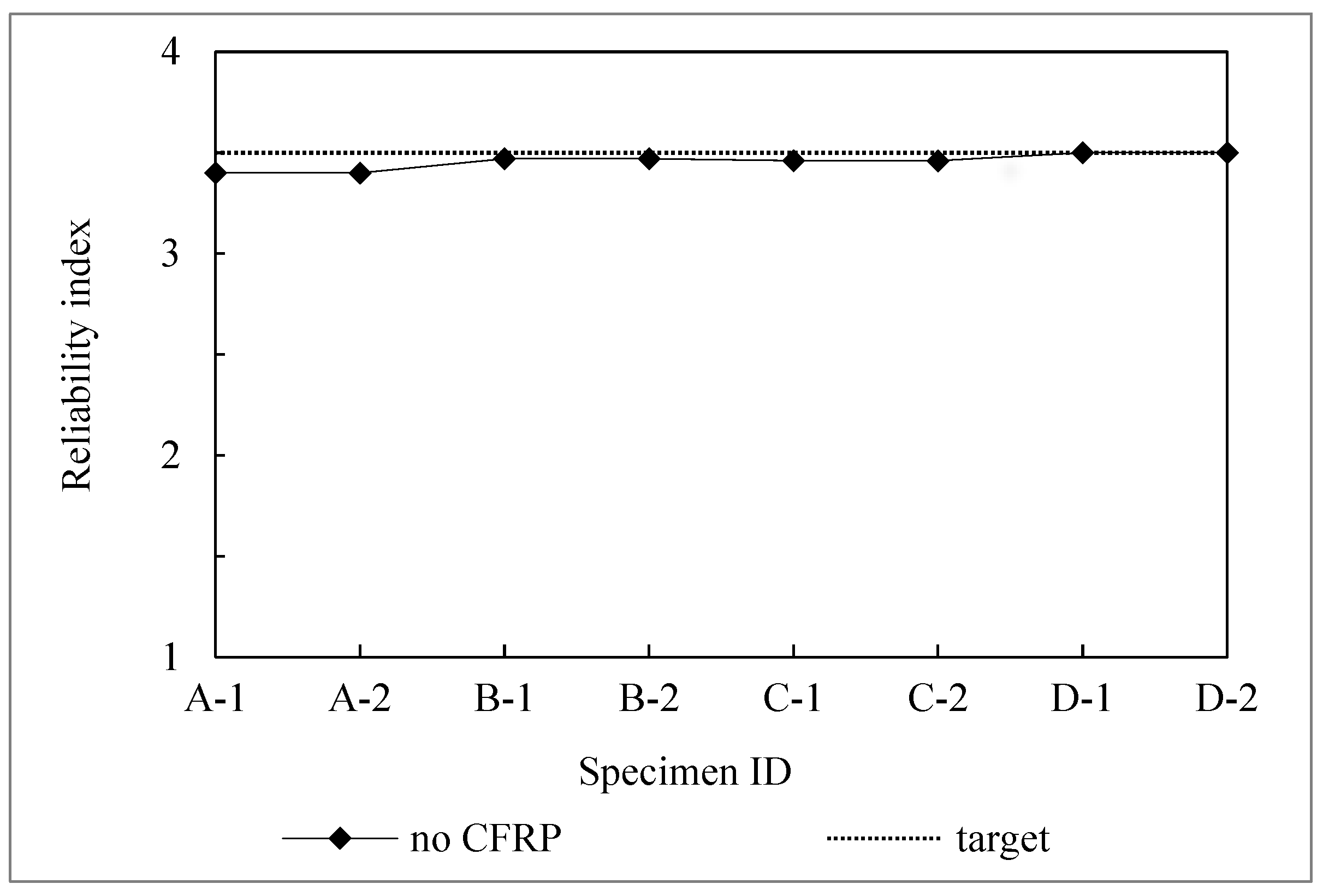
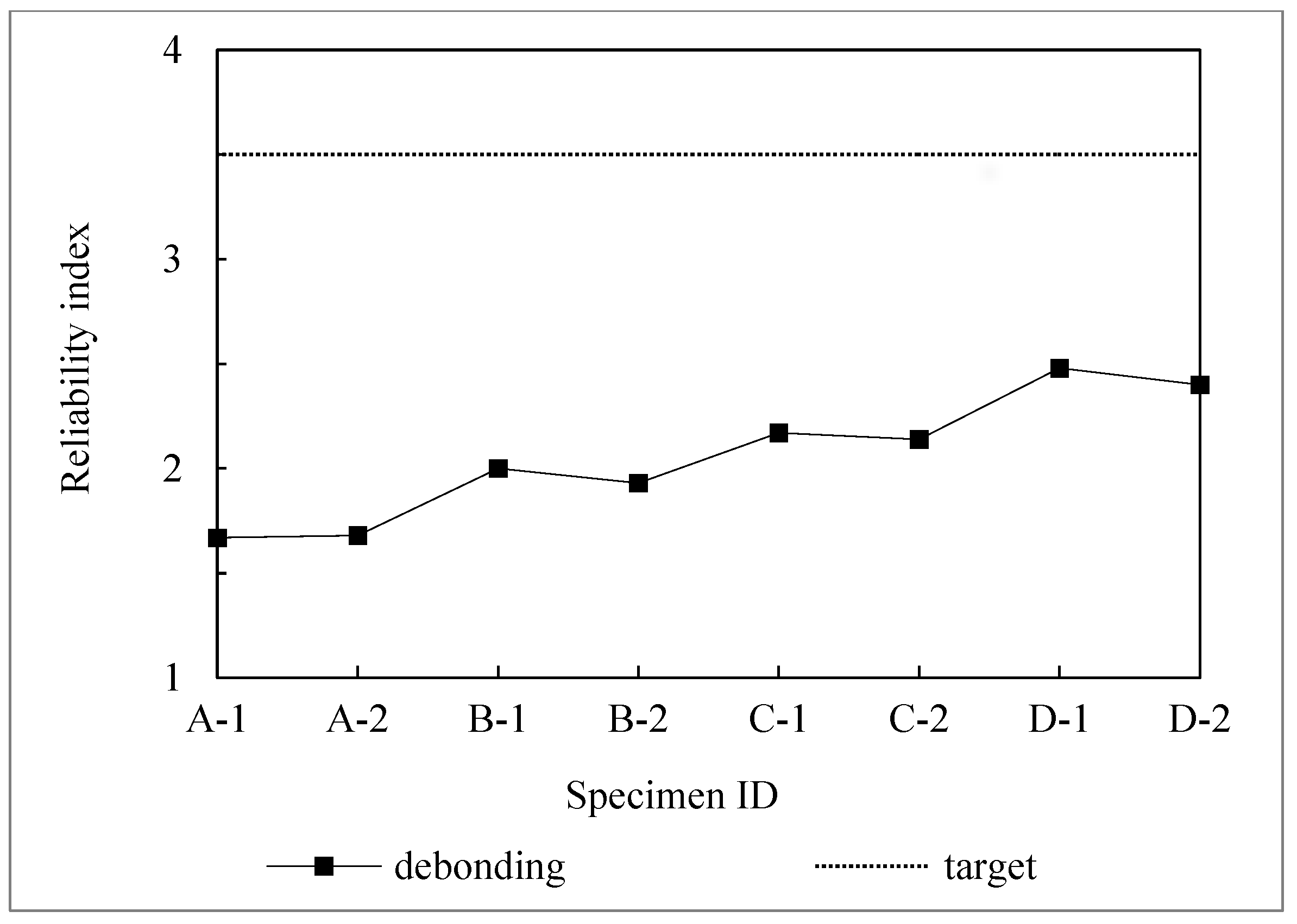
4.1. Reliability Indices of Strength Limit State and Debonding Limit State

The steel bridge girders are designed to adapt to different structural failure modes following the AASHTO LRFD code. According to the results of the reliability study conducted on these girders, the reliability indices of unstrengthened steel I-girders are very near to 3.5 for each and every design scenario. This can be seen by the proximity of the two lines in Figure 5. This indicates that these girders were designed to have a probability of failure that is in accordance with the goal of the AASHTO LRFD code. In this code, the resistance factors and the load are adjusted to have uniform target reliability indices of 3.5 in all limit states. This means that the design of these girders was successful in achieving this goal.
Figure 6 presents the reliability indices of the debonding limit state for eight specimens using the Sika S512-CFRP plate and Sika H514-CFRP plate. Bridge steel Girders with Sika S512-CFRP plates are represented by specimens A-1, B-1, C-1, and D-1, whereas girders with Sika S514-CFRP plates are indicated by specimens A-2, B-2, C-2, and D-2.
Obviously, the reliability indices of the debonding limit state for strengthened steel bridge girders are significantly lower than the target reliability index of 3.5. In detail, the reliability index ranges from 1.67 to 2.48. Hence, the failure probabilities of the girders increase significantly when considering the debonding limit state. In all cases, the debonding limit state reliability indices are relatively consistent, although Sika H514 has a higher modulus than Sika S512. As a result, the debonding failure is not significantly affected by the features of the CFRP plate.

4.2. System Reliability Index of the Strengthened Steel Bridge Girder

In general, the tensile strength of the CFRP plate has a substantial impact on the reliability indices of the girders. The reliability indices of girders dramatically improve after being strengthened with CFRP plate [26,32,33,34]. Figure 7 depicts the reliability indices of specimens using Sika S512. Four types of girder lengths are explored, ranging from 9 to 18 m to 27 to 36 m. In detail, the system reliability indices are more than 5.
Nonetheless, when debonding is taken into account, the reliability index drops significantly. The maximum reliability index is slightly lower than 2.5, which is well below the target reliability index of 3.5. In parallel, the system reliability indices of four specimens (A-2, B-2, C-2, D-2) are higher than 4 when using a Sika H514 CFRP plate with a tensile strength of 1500 MPa, as Figure 8 shown. In comparison, the higher strength tensile CFRP plates that are used to reinforce the steel bridge girders result in a higher reliability index for structure.

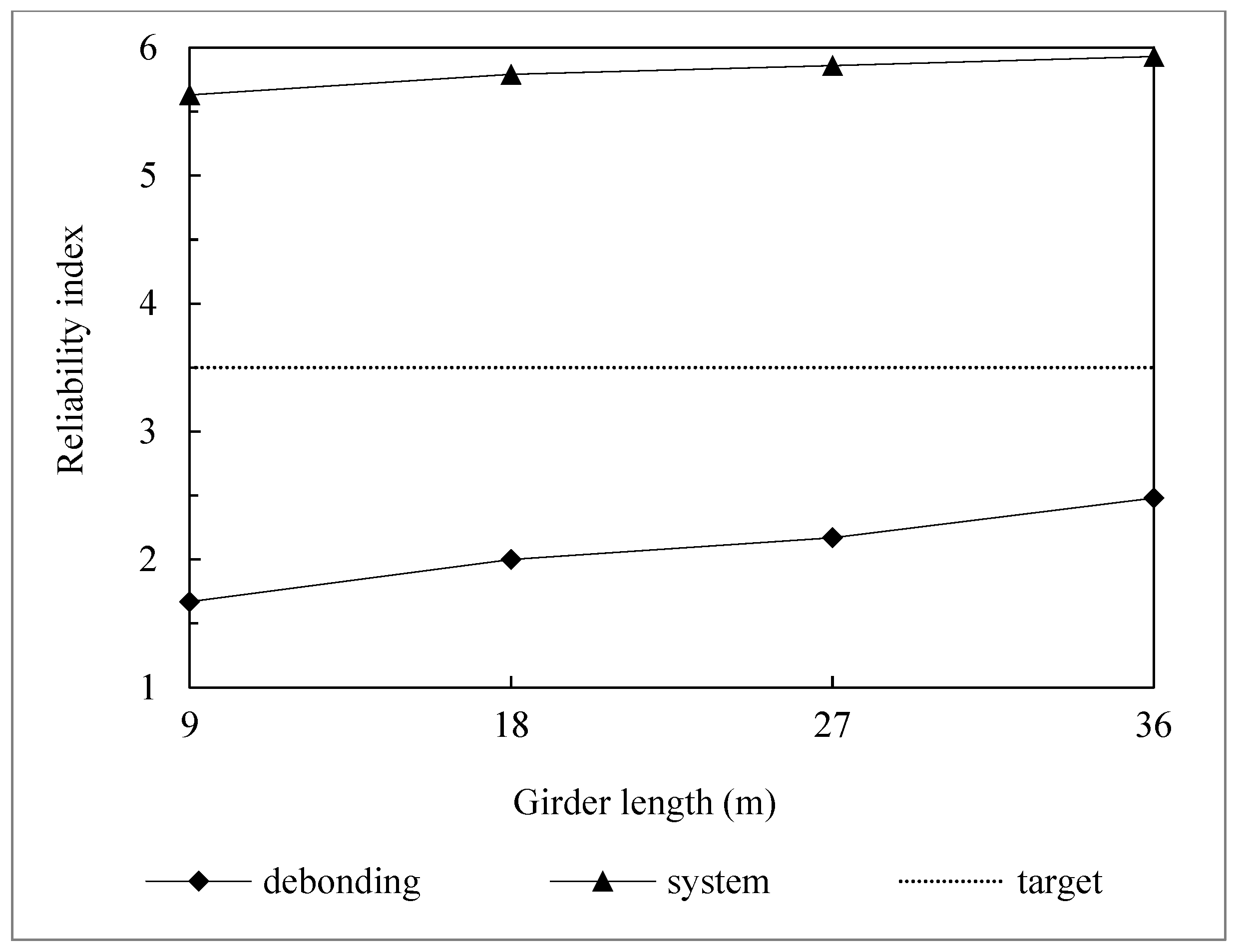
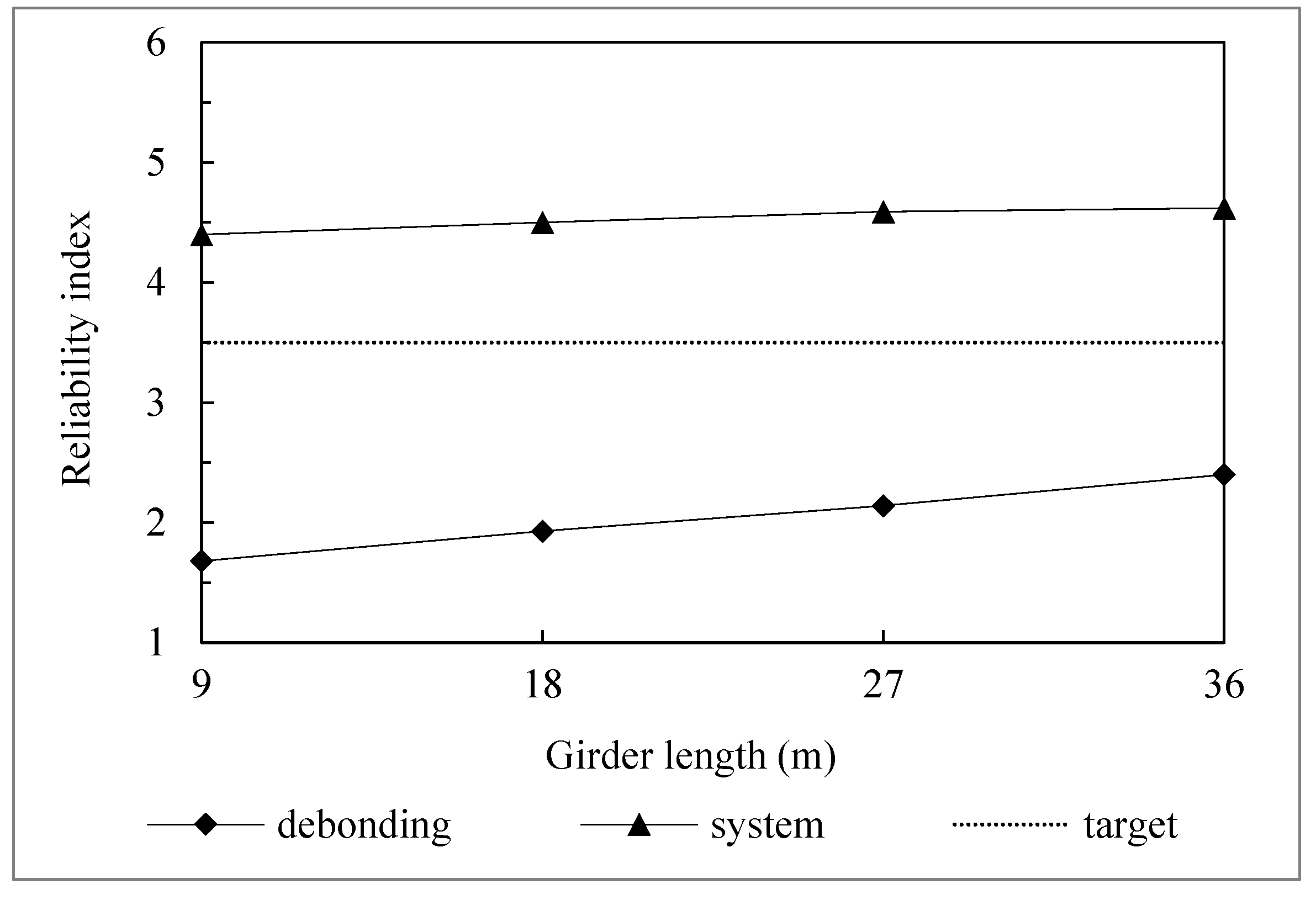
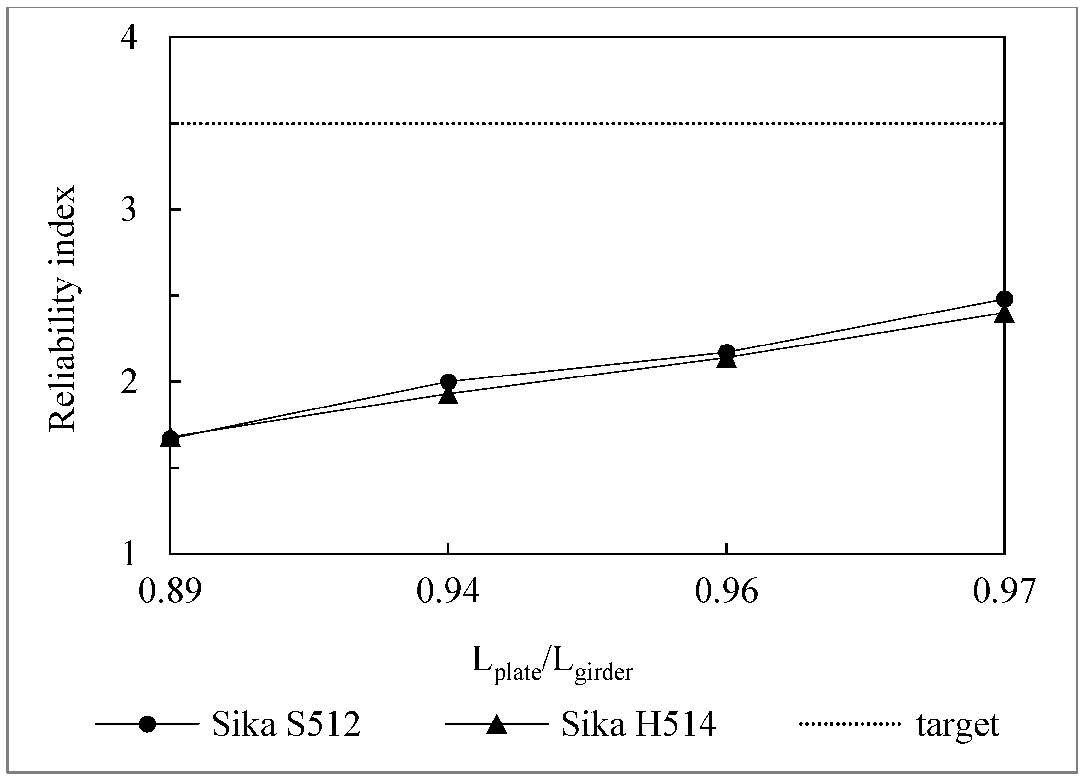
4.3. Effect of the CFRP Plate Length on the Reliability Index

Figure 9 illustrates the analysis of reliability indices for the different plate-to-girder length ratios under considering debonding. Obviously, the reliability index is impacted by the ratio of the length of the CFRP plate to the girder length. When the plate length-to-girder length ratio increases, the distance from the plate ends to the girder ends decreases, and the maximum debonding stress also reduces. Although CFRP plates of specimens have different modulus and tensile strength, the reliability index increases as this ratio increases, as illustrated in Figure 9. It also demonstrates how crucial the length of the CFRP plate is to raise the reliability index of strengthened girders. When reinforcing the bridge girder, it is essential to ensure that the length of the CFRP plate is as long as possible.

5. Conclusions

This paper investigated the reliability analysis for steel bridge girders strengthened with CFRP plates.The margin function for debonding limit state for steel bridge girder reinforced with CFRP has been formulated clearly. In addition, various cases of steel bridge girders reinforced with CFRP plate were designed following the AASHTO LRFD code. Then, the reliability of CFRP-strengthened steel bridge girders by each limit state has been calculated and compared by using a Monte Carlo simulation. The most important findings obtained from this study are as follows:
  • The reliability indices for strengthened steel bridge girders are significantly lower than the target reliability index of 3.5 when considering the debonding of the adhesive layer. The debonding limit state has a substantially lower reliability index than the strength limit state. Hence, debonding limit state should be carefully taken into account when strengthening steel bridge girders using CFRP plates.
  • When considering debonding limit state, reliability indices are relatively similar for steel bridge girders reinforced by Sika H514 CFRP plate or Sika S512 CFRP plate. Thus, the reliability index is not significantly affected by the features of the CFRP plate when debonding occurs.
  • The tensile strength of the CFRP plate has a substantial impact on the reliability indices of the girders. The higher strength tensile CFRP plates that are used to reinforce the steel bridge girders result in a higher reliability index for the girder.
  • The length of the CFRP plate affixed to the steel bridge girder has a considerable impact on its reliability index. As a result, it is critical to ensure that the length of the CFRP plate is as long as possible while strengthening the bridge girder.

Author Contributions

Conceptualization, V.H.D. and Q.V.T.; Methodology, V.H.D. and M.H.N.; Software, Q.V.T. and T.L.H.; Validation, D.H.V.; Formal analysis, D.H.V., V.H.D. and Q.V.T.; Investigation, D.H.V., V.H.D., Q.V.T., M.H.N. and T.L.H.; Resources, Q.V.T. and M.H.N.; Data curation, D.H.V., Q.V.T. and T.L.H.; Writing—original draft, D.H.V., V.H.D. and Q.V.T.; Writing—review & editing, D.H.V. and V.H.D.; Visualization, T.L.H.; Supervision, V.H.D.; Project administration, V.H.D.; Funding acquisition, V.H.D. All authors have read and agreed to the published version of the manuscript.

Funding

This research is funded by Funds for Science and Technology Development of the University of Danang under project number B2019-ĐN02-54.

Data Availability Statement

All data, models, and codes to support the findings of this study are available from the corresponding author upon request.

Conflicts of Interest

The authors declare no conflict of interest.

References

  1. Bakis, C.E.; Bank, L.C.; Brown, V.L.; Cosenza, E.; Davalos, J.F.; Lesko, J.J.; Machida, A.; Rizkalla, S.H.; Triantafillou, T.C. Fiber-Reinforced Polymer Composites for Construction—State-of-the-Art Review. J. Compos. Constr. 2002, 6, 73–87. [Google Scholar] [CrossRef] [Green Version]
  2. Colombi, P.; Fava, G. Fatigue behavior of tensile steel/CFRP joints. J. Compos. Constr. 2012, 94, 2407–2417. [Google Scholar]
  3. Gangarao, H.; Vijay, P. Feasibility Review of FRP Materials for Structural Applications; Technical Report; Constructed Facilities Center Dept. of Civil & Env. Engineering College of Engineering and Mineral Resources West Virginia University: Morgantown, WV, USA.
  4. Khedmatgozar Dolati, S.S.; Mehrabi, A. NSM FRP Pile-Splice System for Prestressed Precast Concrete Piles. Pract. Period. Struct. Des. Constr. 2022, 27, 04022046. [Google Scholar] [CrossRef]
  5. Dolati, S.S.K.; Mehrabi, A. FRP sheet/jacket system as an alternative method for splicing prestressed-precast concrete piles. Case Stud. Constr. Mater. 2022, 16, e00912. [Google Scholar]
  6. Sen, R.; Liby, L.; Mullins, G. Strengthening steel bridge sections using CFRP laminates. Compos. Part B Eng. 2001, 32, 302–322. [Google Scholar] [CrossRef]
  7. Matta, F.; Karbhari, V.M.; Vitaliani, R. Tensile response of steel/CFRP adhesive bonds for the rehabilitation of civil structures. Struct. Eng. Mech. 2005, 20, 589–608. [Google Scholar] [CrossRef]
  8. Dawood, M.; Rizkalla, S.; Sumner, E. Fatigue and overloading behavior of steel concrete composite flexural members strengthened with high modulus CFRP materials. J. Compos. Constr. 2007, 11, 659–669. [Google Scholar] [CrossRef] [Green Version]
  9. Esfahani, M.R.; Kianoush, M.R.; Tajari, A.R. Flexural behavior of reinforced concrete beams strengthened by CFRP sheets. Eng. Struct. 2007, 29, 2428–2444. [Google Scholar] [CrossRef]
  10. Fernando, D.; Yu, T.; Teng, J.G.; Zhao, X.L. CFRP strengthening of rectangular steel tubes subjected to end bearing loads: Effect of adhesive properties and finite element modeling. Thin-Wall. Struct. 2009, 47, 1020–1028. [Google Scholar] [CrossRef]
  11. Teng, J.G.; Yu, T.; Fernando, D. Strengthening of steel structures with fiber reinforced polymer composites. J. Constr. Steel Res. 2012, 78, 131–143. [Google Scholar] [CrossRef]
  12. Jenarthanan, M.P.; Jeyapaul, R. Machinability study of carbon fiber reinforced polymer (CFRP) composites using design of experiment technique. Pigment. Resin Technol. 2014, 43, 35–44. [Google Scholar] [CrossRef]
  13. Sahin, M.U.; Dawood, M. Experimental investigation of bond between high modulus CFRP and steel at moderately elevated temperatures. J. Compos. Constr. 2016, 20, 04016049. [Google Scholar] [CrossRef]
  14. Lee, M.S.; Kang, C.G. Determination of forming procedure by numerical analysis and investigation of mechanical properties of steel/CFRP hybrid composites with complicated shapes. Compos. Struct. 2017, 164, 118–129. [Google Scholar] [CrossRef]
  15. Szewczak, I.; Rozylo, R.; Rzeszut, K. Influence of Mechanical Properties of Steel and CFRP Tapes on the Effectiveness of Strengthening Thin-Walled Beams. Materials 2021, 14, 2388. [Google Scholar] [CrossRef] [PubMed]
  16. Pawlak, A.M.; Górny, T.; Dopierała, Ł.; Paczos, P. The Use of CFRP for Structural Reinforcement—Literature Review. Metals 2022, 12, 1470. [Google Scholar] [CrossRef]
  17. Salama, T.; Abd-El-Meguid, A.S. Strengthening Steel Bridge Girders Using CFRP; Technical Report; Department of Civil, Construction, and Environmental Engineering, The University of Alabama at Birmingham: Birmingham, AL, USA, 2010. [Google Scholar]
  18. Lenwari, A.; Thepchatri, T.; Albrecht, P. Debonding Strength of Steel Beams Strengthened with CFRP Plates. J. Compos. Constr. 2006, 10, 69–78. [Google Scholar] [CrossRef]
  19. Nozaka, K.; Shield, C.K.; Hajjar, J.F. Effective Bond Length of Carbon-Fiber-Reinforced Polymer Strips Bonded to Fatigued Steel Bridge I-Girders. J. Bridge Eng. 2005, 10, 195–205. [Google Scholar] [CrossRef]
  20. Stratford, T.; Cadei, J. Elastic analysis of adhesion stresses for the design of a strengthening plate bonded to a girder. Constr. Buil. Mater. 2006, 20, 34–45. [Google Scholar] [CrossRef] [Green Version]
  21. Liu, M.; Dawood, M. Reliability analysis of debonding in steel girders strengthened with externally bonded CFRP composites. J. Compos. Constr. 2019, 23, 65–70. [Google Scholar] [CrossRef]
  22. Schnerch, D.; Dawood, M.; Rizkalla, S.; Summer, E. Propose design guidelines for strengthening steel bridges with FRP materials. Constr. Buil. Mater. 2007, 21, 1001–1010. [Google Scholar] [CrossRef]
  23. Nowak, A.S.; Collins, K.R. Reliability of Structures, 2nd ed.; CRC Press: Boca Raton, FL, USA, 2013; ISBN -13-978-0415675758. [Google Scholar]
  24. Zhao, X. FRP-Strengthened Metallic Structures; CRC Press: Boca Raton, FL, USA, 2014; ISBN -9781138074330. [Google Scholar]
  25. Liu, M.; Dawood, M. Reliability analysis of adhesively bonded CFRP-to-steel double lap shear joint with thin outer adherends. Constr. Build. Mater. 2017, 141, 52–63. [Google Scholar] [CrossRef] [Green Version]
  26. Nowak, A.S. System reliability models for bridge structures. Bull. Pol. Acad. Sci. Tech. Sci. 2004, 52, 321–328. [Google Scholar]
  27. Stanojev, M.; Stojić, D. Reliability analysis of structures. Archi. Civil Eng. 2014, 12, 265–272. [Google Scholar] [CrossRef]
  28. Al-Shawaf, A.; Al-Mahaidi, R.; Zhao, X.L. Effect of elevated temperature on bond behaviour of high-modulus CFRP/steel doublestrap joints. Aust. J. Struct. Eng. 2009, 10, 63–74. [Google Scholar] [CrossRef]
  29. Qureshi, H.J.; Saleem, M.U.; Khurram, N.; Ahmad, J.; Amin, M.N.; Khan, K.; Aslam, F.; Al Fuhaid, A.F.; Arifuzzaman, M. Investigation of CFRP Reinforcement Ratio on the Flexural Capacity and Failure Mode of Plain Concrete Prisms. Materials 2022, 15, 7248. [Google Scholar] [CrossRef]
  30. Bigaud, D.; Ali, O. Time-variant flexural reliability of RC beams with externally bonded CFRP under combined fatigue-corrosion actions. Reliab. Eng. Syst. Saf. 2014, 131, 257–270. [Google Scholar] [CrossRef] [Green Version]
  31. Wang, K.; Xu, H.; Qu, F.; Wang, X.; Shi, Y. A reliability analysis framework with Monte Carlo simulation for weld structure of crane’s beam. AIP Conf. Proc. 2018, 1955, 030024. [Google Scholar]
  32. Bresson, G.; Jumel, J.; Shanahan, M.E.R.; Serin, P. Statistical aspects of the mechanical behavior of a paste adhesive. Inter J. Adhes. Adhes. 2013, 40, 70–79. [Google Scholar] [CrossRef]
  33. Wu, C.; Zhao, X.; Hui Duan, W.; Al-Mahaidi, R. Bond characteristics between ultra-high modulus CFRP laminates and steel. Thin-Walled Struct. 2012, 51, 147–157. [Google Scholar] [CrossRef]
  34. Ferrier, E.; Bigaud, D.; Hamelin, P.; Bizindavyi, L.; Neale, K.W. Fatigue Reliability of External Bonded CFRP Used for Concrete Structure. Mater. Struct. 2005, 38, 39–46. [Google Scholar] [CrossRef]
Figure 1. Detail of loads carried by strengthened steel I-girder.
Designs 06 00126 g001
Figure 2. Equilibrium between girder, adhesive, and CFRP plate.
Designs 06 00126 g002
Figure 3. A typical sample of CFRP-reinforced steel I-girder.
Designs 06 00126 g003
Figure 4. Flow chart of reliability index analysis.
Designs 06 00126 g004
Figure 5. Reliability indices of steel girder without CFRP.
Designs 06 00126 g005
Figure 6. Reliability indices of debonding limit state.
Designs 06 00126 g006
Figure 7. Reliability indices of specimens using Sika S512.
Designs 06 00126 g007
Figure 8. Reliability indices of specimens using Sika H514.
Designs 06 00126 g008
Figure 9. Reliability indices of debonding limit state for the different length ratios.
Designs 06 00126 g009
Table 1. The dimensions of specimens using Sika S512.
Specimen
ID
Steel GirderCFRP PlateAdhesive
Girder Length (m)Girder Height (mm)Thickness of Web
(mm)
Width of Flange (mm)Thickness of Flange (mm)Plate Length (m)Plate Width (mm)Plate Thickness (mm)Adhesive Width (mm)Adhesive Thickness (mm)
A-19560153201883203.03202.0
B-11810002040022174004.33702.0
C-12715002241024264105.53402.0
D-13618002450028355006.24402.0
Table 2. The dimensions of specimens using Sika H514.
Specimen IDSteel GirderCFRP PlateAdhesive
Girder Length (m)Girder Height (mm)Thickness of Web
(mm)
Width of Flange (mm)Thickness of Flange (mm)Plate Length (m)Plate Width (mm)Plate Thickness (mm)Adhesive Width (mm)Adhesive Thickness (mm)
A-29560153201883202.73201.5
B-21810002040022174003.83701.5
C-22715002241024264104.93401.5
D-23618002450028355005.54401.5
Table 3. The characteristics of CFRP.
CFRPTensile Strength (MPa)E-Modulus (GPa)
Sika® carbodur® S5122800 a165 a
Sika® carbodur® H5141500 a300 a
a Information provided by the manufacturer.
Table 4. The characteristics of the adhesive.
Adhesiveσa (MPa)E-Modulus (GPa)
Sikadur®-3056.511.2
Table 5. The statistical characteristics of parameters.
ParametersBiasCOVDistribution
Maximum stress of adhesive layer (σr)1.300.333Lognormal
Resistance modeling uncertainty (ξr)1.200.221Gamma
Modulus of the adhesive layer (Ea)1.000.084Lognormal
Adhesive layer thickness (ta)0.930.098Lognormal
Bending moment due to self-weight (DC)1.030.080Normal
Bending moment due to wearing surface load (DW)1.000.250Normal
Bending moment due to live load (LL)Varies bVaries bNormal
Flange width of the steel girder (bf)1.001.5 × 10−3Normal
Steel girder’s web height (D)1.001.5 × 10−3Normal
Flange thickness of steel girder (tf)1.001.5 × 10−3Normal
Web thickness of steel girder (tw)1.001.5 × 10−3Normal
CFRP tensile strength (fp)1.000.110Normal
Steel yield strength (fy)1.120.100Lognormal
b See Table 6.
Table 6. The statistical characteristics of live load [21].
Girder Length (m)BiasCOVDistribution
91.430.12Normal
181.430.12Normal
271.420.12Normal
361.410.12Normal
Table 7. Results of computing the reliability index of steel girder.
Specimen ID0dst
A-13.401.675.63
A-23.401.684.40
B-13.472.005.79
B-23.471.934.50
C-13.462.175.86
C-23.462.144.59
D-13.502.485.93
D-23.502.404.62
Publisher’s Note: MDPI stays neutral with regard to jurisdictional claims in published maps and institutional affiliations.

