Article

Towards the Mechatronic Development of a New Upper-Limb Exoskeleton (SAMA)

1
Mechanical Engineering Department, Arab Academy for Science and Technology and Maritime Transport, Smart-Village Branch, Cairo 11736, Egypt
2
Mechanical Engineering Department, Arab Academy for Science and Technology and Maritime Transport, Cairo 11757, Egypt
*
Author to whom correspondence should be addressed.
Designs 2022, 6(5), 80; https://doi.org/10.3390/designs6050080
Submission received: 1 August 2022 / Revised: 3 September 2022 / Accepted: 5 September 2022 / Published: 8 September 2022
(This article belongs to the Section Bioengineering Design)

Abstract

:
Modern neuromuscular rehabilitation engineering and assistive technology research have been constantly developing in the last 20 years. The upper body exoskeleton is an example of an assistive rehabilitation device. However, in order to solve its technological problems, interdisciplinary research is still necessary. This paper presents a new three-degrees of freedom (DOF) active upper-body exoskeleton for medical rehabilitation named “SAMA”. Its mechanical structure is inspired by the geometry and biomechanics of the human body, particularly the ranges of motion (ROM) and the needed torque. The SAMA exoskeleton was manufactured and assembled into an ergonomic custom-made wheelchair in a sitting posture in order to provide portability and subject comfort during experimental testing and rehabilitation exercises. Dynamic modeling using MATLAB–Simulink was used for calculating the inverse kinematics, dynamic analysis, trajectory generation and implementation of proportional–integral–derivative (PID) computed torque control (PID-CTC). A new framework has been developed for rapid prototyping (the dynamic modeling, control, and experimentation of SAMA) based on the integration between MATLAB–Simulink and the Robot Operating System (ROS) environment. This framework allows the robust position and torque control of the exoskeleton and real-time monitoring of SAMA and its subject. Two joints of the developed exoskeleton were successfully tested experimentally for the desired arm trajectory. The angular position and torque controller responses were recorded and the exoskeleton joints showed a maximum delay of 200° and a maximum steady state error of 0.25°. These successful results encourage further development and testing for different subjects and more control strategies.

1. Introduction

Stroke is among the leading causes of adult disability [1]. It is caused by an interruption of the blood flow to the brain, which results in brain cell damage, and it can be fatal. Stroke patients may endure paralysis or loss of physical strength on one side of the body (hemiparesis), as well as memory impairments, making activities of daily living (ADL) challenging. The most common treatment for these deficits is rehabilitation, which helps stroke victims to relearn the best possible use of their limbs and reclaim their independence [2].
Most of the stroke burden worldwide is experienced by countries with less developed economies and lower incomes. Recent reports from the World Health Organization (WHO) state that low and middle-income countries have a high number of stroke patients; seven times the number of patients in high-income countries. It is worth mentioning that 80% of these stroke cases cause death [3].
Egypt is the most populated nation in the Middle East and the third most populous on the African Continent. Although there are physiotherapy units in most major healthcare hospitals in Egypt, multidisciplinary, progressive, and goal-oriented recovery services are missing. Besides this, the actual numbers of stroke patients and the methods of their treatment are relatively unknown [4].
Stroke patients go through three stages after the stroke: first, the acute stage, which lasts one week; second, the sub-acute stage, which lasts six months; and third, the chronic stage [5]. Stroke-related arm and wrist impairment are the most common complications [6]. Rehabilitation can help in treating or lessening the effects of the stroke [7]. Rehabilitation also necessitates the use of a trained therapist to conduct repetitive motions of the affected limb [2,8]. However, proficient therapists’ availability, therapeutic session duration, and the expense of rehabilitation tools are all issues that affect both the therapist and the patient [9]. Furthermore, one-on-one contact between the therapist and the patient is required in rehabilitation programs. Nevertheless, interactive rehabilitation is time-consuming and labor-intensive for both the therapist and the patient [10]. Additionally, the COVID-19 pandemic has had a terrible impact on physiotherapy delivery thus far. A correlation between minimally symptomatic COVID-19 individuals and the risk of severe stroke has recently been established [9]. Exoskeletons are also used for physical injuries that exist because of increased sedentary behavior, poor home-office setups, and excessive or dangerous exercises [11].
Considering all of these factors, an intelligent and sophisticated solution is needed. One of the most recent and effective solutions for stroke therapy is the use of assistive exoskeletons, especially for the treatment of upper limb injuries [12]. A robotic exoskeleton is an active orthosis device that helps patients with mobility and manipulation-related disabilities and restores their capability to perform daily life activities [13].
Exoskeleton development has been thoroughly documented over the last 50 years. In the 1960s, Cornell University researchers developed “The Superman Suit”, a wearable mechanical device weighing around 15.8 kg. The user may lift up to 1000 pounds using this device. In the meantime, G.E. researchers created a two-armed handling apparatus for manipulating radioactive material [14,15]. In around the same era, researchers at Johns Hopkins University produced an upper limb exoskeleton that allowed paralyzed people to achieve elbow flexion [16]. These findings prompted researchers to develop rehabilitation robots that can be utilized as therapy aids. In addition to providing repeated motions for a patient’s limb [17], rehabilitation robots provide intensive, accurate, quantitative, and safe therapy [18]. The biomedical and engineering sectors have paid a lot of attention to the upper body exoskeletons that have been used for services and rehabilitation in the previous two decades. Upper body exoskeleton technology is gaining attention as a reliable option for physically challenged or disabled persons [19]. KosVest [20] and FORTIS [21] are two examples of exoskeletons that have been designed to boost the wearer’s performance and strength compared to their regular human effort. Exoskeletons can be used as power amplification devices or for rehabilitation purposes. This research is concerned with the rehabilitation type.
Several research efforts aim to develop robotic assistive rehabilitation devices for fast motor recovery. Vélez-Guerrero et al. [22] have developed a compact one-DOF exoskeleton for the elbow joint that allows flexion-extension rotation. The developed controller allows operation in autonomous mode, remote control mode, or leader–follower mode. The system actuators are controlled by an AI-based neural processing unit. Another assistive prototype was presented by Birouas et al. [23] who developed an underactuated robotic hand using 3D printing technology. During the development process for the aforementioned prototype, the behavior of the biological hand was studied, and multiple feedback sensors were used to determine the symmetric and asymmetric behaviors that are related to torque, position, trajectory, and laws of motion. One actuator was used to move each finger and the motion was transmitted from the motor to the finger using tendon-sheath transmission. Gull et al. [24] developed a four-DOF upper limb exoskeleton, mounted on a wheelchair, for rehabilitation. A PD position controller was used to validate the trajectory planning of the exoskeleton for two exercises: a drinking task and an object picking task.
However, this technology is still challenged in the areas of mechanical design, control, and human–robot interaction, despite its high utility and its growing demand. Dynamic and kinematic analyses are two issues in developing an ergonomic exoskeleton system [25]. Since wearable exoskeletons interact with humans directly, careful analysis and control are always pursued. Robot kinematics’ application to human body kinematics is a complex matter due to the availability of multiple solutions to joint variables and due to its iterative, non-unique, and time-consuming calculations. Dynamic analysis is also a complex matter. In this analysis, the forces and torques causing the motion of the upper body exoskeletons are calculated, which is also a time-consuming and complicated calculation. Different methodologies of position and torque control are sought after to provide robust and smooth control trajectories for the intended subjects, such as those for upper limb exoskeletons [26]. Recently, rapid prototyping software has been developed to calculate the kinematics and dynamics and to deploy robust control methodologies. A. Caballero et al. proposed a rapid prototyping solution for exoskeleton control. The developed software was tested and achieved accurate and fast responses [27].
Various linear–nonlinear control algorithms have been proposed by researchers to increase robot maneuverability and perform various forms of physical rehabilitation efficiently [28]. Nonlinear robot dynamics have been addressed using both linear and nonlinear control techniques. Most nonlinear control system algorithms are based on the plant’s mathematical model (robot dynamics model). Hence, it is critical to construct an accurate plant model because it is an element of the control architecture.
Although proportional–integral–derivative (PID) controllers and their derivative approaches are simple and classical, they are dependable controllers in most systems due to their ease of generating controller gains and accurate performance evaluation. Some other control algorithms are vulnerable to modeling errors, while others are more resistant to parameter or modeling uncertainty. Many researchers use PID controllers and enhance their performance by adding other control methods, such as modern control or artificial intelligence techniques [29]. One of these methods is the PID-CTC, which is designed around the robot’s dynamic model. Due to its ability to provide asymptotic stability with fixed positive definite gain matrices, it is a popular robot motion-control approach [30]. Moreover, CTC is notable for its reliability and robust performance [31], especially when it is used for non-linear, dynamically coupled, and complex robotic systems [32]. CTC solves these problems by utilizing two functions. First, it uses the feedback linearization technique to linearize the nonlinear system and, second, it generates a control input that matches the performance criteria.
Other problems for upper exoskeletons lie in the excessive weight of their parts and actuators, which form an effort-consuming problem for the wearer. A compact and lightweight wearable exoskeleton is always a desirable option. Falkowski et al. presented a light exoskeleton design [33] without losing any advantage in the load-carrying capacity or the number of joints.
In the proposed prototype, SAMA, a new upper limb exoskeleton, is presented. In this prototype, solutions to the previously mentioned problems are addressed and implemented. The proposed design is light and compact with electrical actuators for three DOF of the arm. The kinematic and dynamic complexity of the mechanism was solved by using dynamic modeling software. A position/torque control framework was built to drive the mechanism in the simulation and generate the necessary trajectories and torques for SAMA’s joints. In addition, the generated torques and trajectories were sent to SAMA using the MATLAB–ROS bridged environment.
This paper is organized as follows. The anatomy of the human arm is detailed in Section 2, followed by the proposed design of SAMA. In Section 3, there is a description of the rapid prototyping software that was used to model the exoskeleton, calculate its kinematics, generate its dynamic model, and implement the PID-CTC for position tracking and torque generation. The selection of the actuators, sensors, and system assembly are discussed in Section 4. The control system architecture is presented in Section 5. The system framework controller is shown including the MATLAB–ROS bridged communication environment [34]. In Section 6, there is a description of the SAMA exoskeleton’s testing on a human subject in order to evaluate the joint movements, torques, designed control framework, and system responses. Finally, in Section 7, the paper is concluded with a discussion of the obtained results and possible future work.

2. Mechanical Design

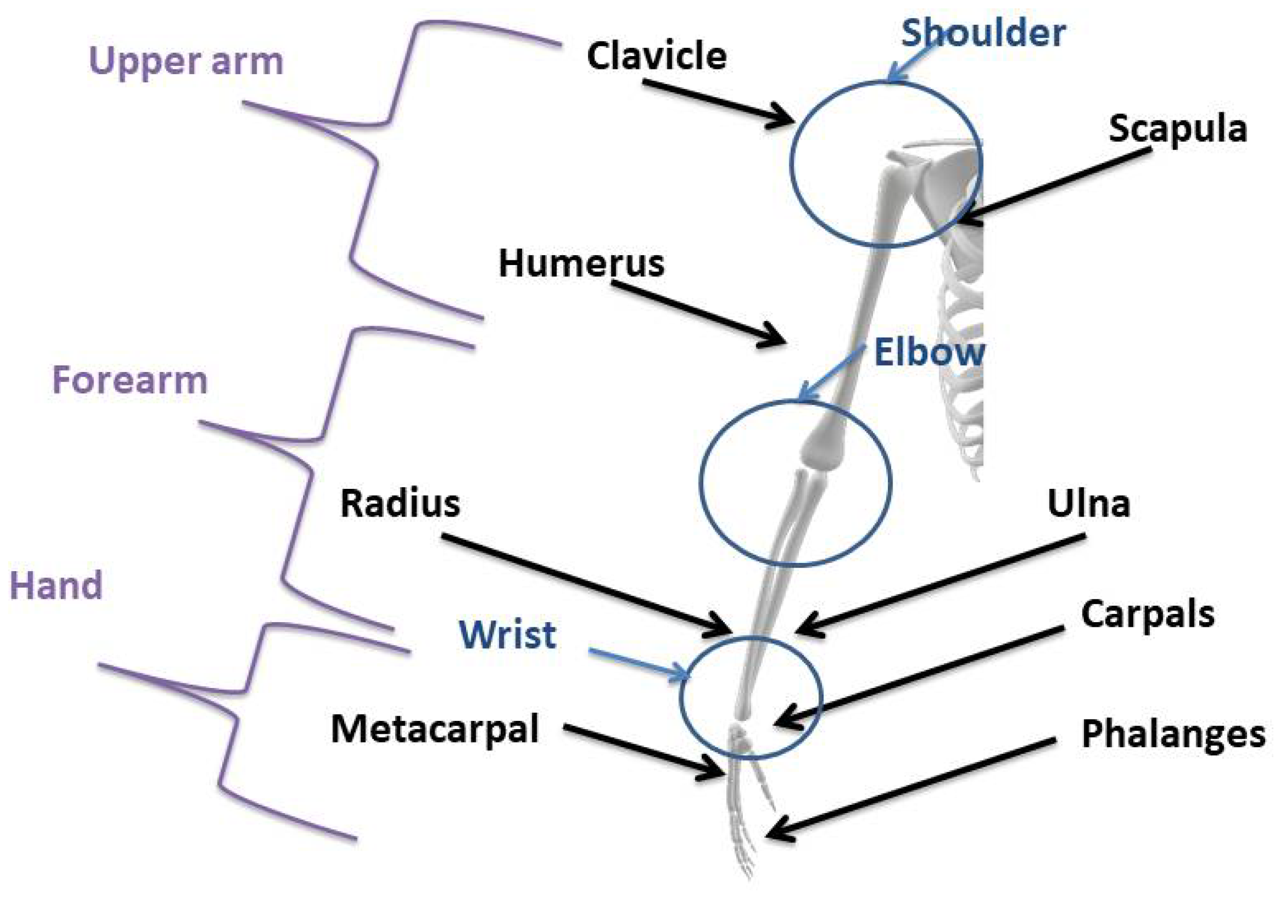
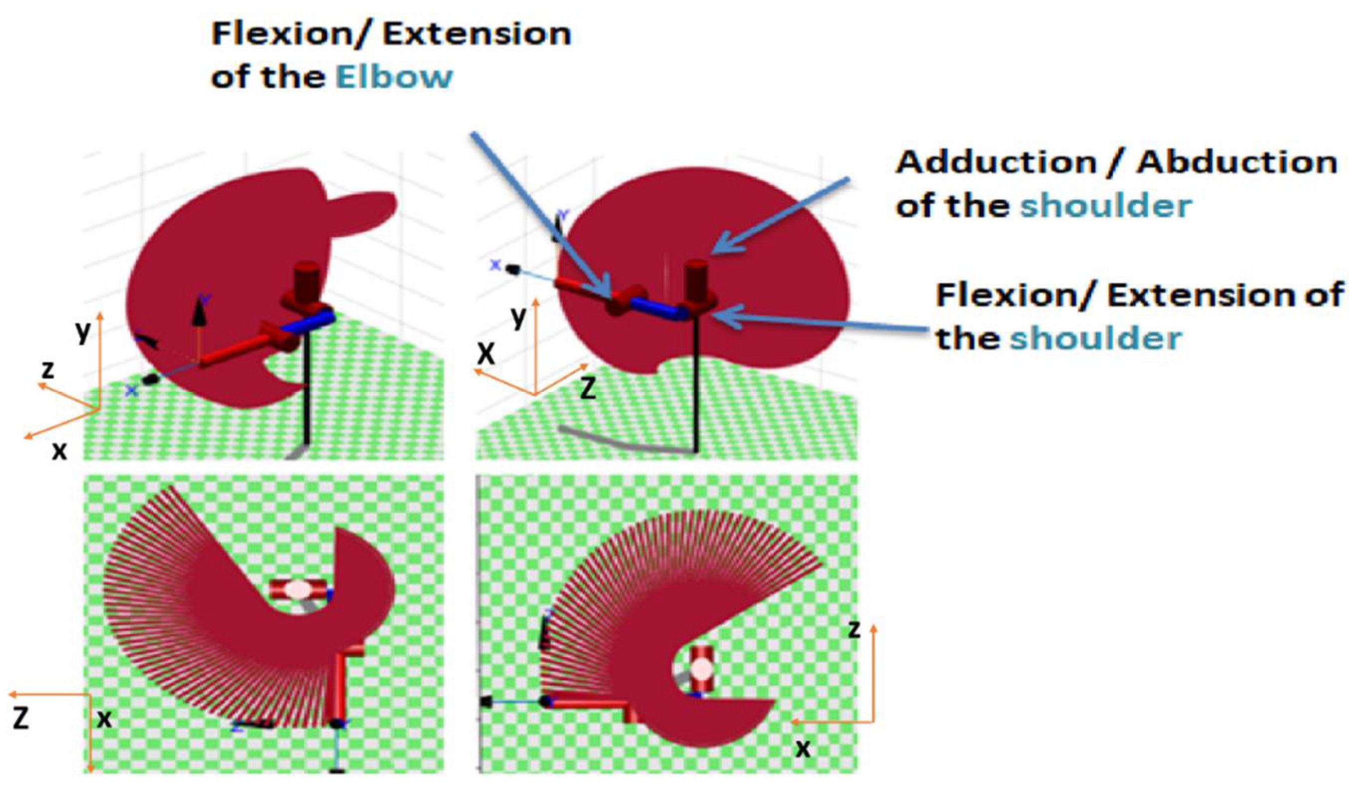
2.1. Anatomy of the Human Arm

The upper limb is the part of the body that connects to the trunk through the shoulder. The upper limb is composed of three parts: the arm, forearm, and hand. The elbow connects the forearm to the arm. As can be seen in Figure 1, the wrist links the forearm to the hand [35].
The human arm has seven DOF: three on the shoulder, one on the elbow, and three on the wrist [36,37]. The shoulder is regarded as a ball and socket joint that allows three rotations: flexion/extension (Figure 2a), abduction/adduction (Figure 2b), and internal/external rotations (Figure 2c). The elbow has one degree of freedom: flexion/extension (Figure 2d). Finally, there are three degrees of freedom in the wrist joint: pronation/supination (Figure 2e), flexion/extension (Figure 2f), and ulnar/radial deviations (Figure 2g).
According to the Hanavan model, the joint dimensions and angles can be generated by using the subject geometry, as is illustrated in Figure 3 [37]. A male subject was chosen for the implementation of SAMA. He was 25 years old, weighed 800 N, and was 1.85 m tall at the time of the experiment. His arm measurements and the ranges of motion of his arm joints are listed in Table 1. These data were later used to perform the kinematic study of the arm and joint motions of SAMA, as will be illustrated in Section 3. These measurements depend on a certain posture of the arm where the subject’s upper arm is in the horizontal position.

2.2. Mechanical Design Considerations

In this research, the SAMA exoskeleton was intended to have three DOF. Two active DOF for shoulder rehabilitation and one active DOF for elbow rehabilitation. Several ergonomic features were prioritized during the mechanical design. The exoskeleton arm was mounted on a wheeled rehabilitation chair for the placement and testing of the arm and portability if needed as shown in Figure 4. A light aluminum alloy was chosen as the design material of the exoskeleton due to its considerably low weight, low cost, and modularity in reshaping. Flexible medical straps were fixed on the shoulder and the forehand for the easy fixation of the human arm. The back of the chair was designed using reinforced plastic with lumbar support and a cushioning aid in order to decrease strain and provide relief for the human back.

3. Modeling of the SAMA Exoskeleton

Modeling was necessary for our prototype in order to evaluate the behavior of the system and to analyze and validate applicable control methods in a secure environment. Both the kinematics and the dynamics of the prototype are illustrated in this section.

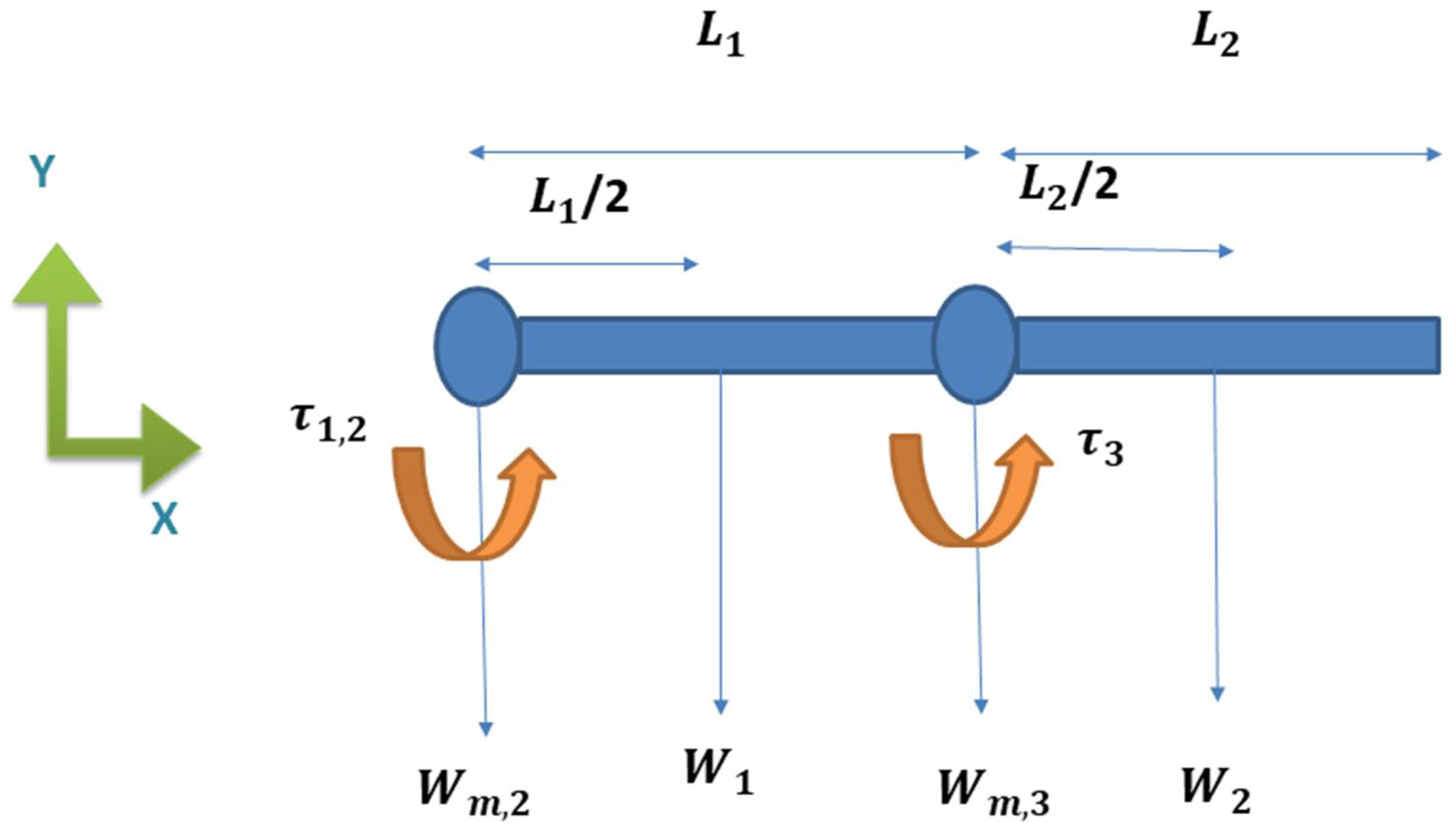
3.1. Kinematic Calculations

Forward kinematic analysis was performed using Denavit–Hartenberg (DH) convection. The kinematic scheme of the SAMA exoskeleton is shown in Figure 5. The calculated DH parameters are given in Table 2.
Where θ i is the joint angle, d i is the joint distance, a i is the link length, and α i is the link twist angle. Additionally, the general transformation matrices defining frame R i relative to frame R i 1 are given as:
T 1 0 = [ C 1 0 S 1 0 S 1 0 C 1 0 0 1 0 L 1 0 0 0 1 ]
T 2 1 = [ C 2 S 2 0 L 3 C 2 S 2 C 2 0 L 3 S 2 0 0 1 L 2 0 0 0 1 ]
T 3 2 = [ C 3 S 3 0 L 4 C 3 S 3 C 3 0 L 4 S 3 0 0 1 0 0 0 0 1 ]
T 3 0 = T 1 0 T 2 1 T 3 2 = [ C 1 C 23 C 1 S 23 S 1 L 2 S 1 L 3 C 1 C 2 L 4 C 1 C 2 C 3 + L 4 C 1 S 2 S 3 S 1 C 23 S 1 S 23 C 1 L 4 S 1 S 2 S 3 L 3 C 2 S 1 L 4 S 1 C 2 C 3 L 2 C 1 S 23 C 23 0 L 4 S 23 L 1 + L 3 S 2 0 0 0 1 ]  
where the following symbols are used:
C k = c o s ( θ k )
S k = s i n ( θ k ) ,
C 12 = c o s ( θ 1 + θ 2 )
S 12 = s i n ( θ 1 + θ 2 )
Moreover, the position of any arbitrary point P can be represented in frame “j” concerning frame “i” using the transformation matrix T i j , where P j = T i j P i . Hence, the position of the end effector concerning frame “3” can be represented concerning frame “0” by P 0 = T 3 0 P 3 . When the range of motions was compared to the bio-mechanical data in Table 1, it was observed that the exoskeleton had a ROM that is suitable for the test subject. For further verification, the obtained ROM was compared with that of the shoulder and elbow joints of other upper limb exoskeletons, as can be seen in Table 3.

3.2. Dynamic Modeling

The dynamic modeling was carried out using Simscape Multibody library in MATLAB–Simulink. Dynamic multi-body modeling is a safe way to test exoskeleton control systems because it allows both the human limb’s and exoskeleton’s dynamics to be modeled together [40]. The mass and inertial characteristics of a typical adult’s upper limb were used in the model, as shown in Table 4. The masses and inertial characteristics of the test subject’s upper limb were exported to MATLAB–Simulink. Moreover, the dynamic physical model was constructed from the CAD model and exported to the MATLAB–Simulink environment using the Simscape Multibody library, as shown in Figure 6.
SAMA’s dynamic model is composed of rigid body subsystems that are connected by revolute joints. It also includes a reference frame, a mechanism configuration (which specifies the mechanical and simulation characteristics that apply to the complete machine), and a solver configuration (which specifies the solver settings for the simulation). Figure 7 illustrates the dynamic multi-body physical model of the SAMA exoskeleton.
The rigid body tree model of the SAMA exoskeleton was imported from Simscape Multibody, so the robotics system toolbox could be used for inverse kinematics, trajectory generation, and dynamics analysis. The robot’s structure was represented by the rigid body tree model.

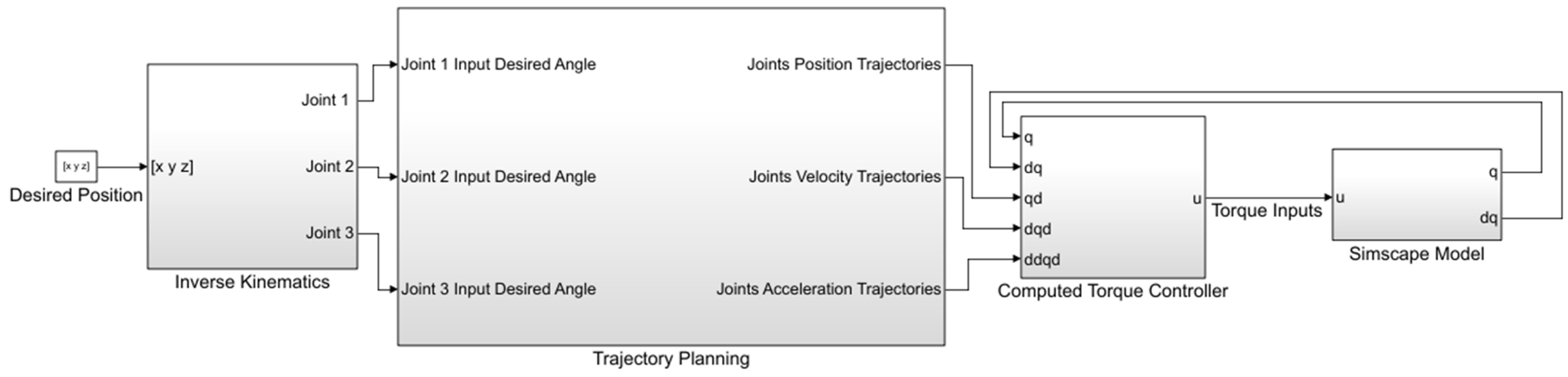
3.2.1. Inverse Kinematics

Humans have a remarkable ability to plan and execute a motion in both the task space and the joint space [41]. The ability to move between these two planning processes allows humans to perform a wide range of complex motions in order to achieve several functional goals. The most popular method of controlling robots is joint space control, which uses a single motor for each degree of freedom. By transforming motion from the task space to the joint space, inverse kinematics attempts to assist in bridging the gap between motor control and end-effector motion.
Inverse kinematic analysis is an iterative, non-unique, and time-consuming process. So, in this research, MATLAB–Robotics System Toolbox was used to perform the inverse kinematics analysis. The defined XYZ coordinates were converted to homogeneous transformations and input as the desired pose and a [1 × 6] vector of the weights on the tolerance for the orientation and position of the end effector was defined as an input for the inverse kinematics block. The output inverse-kinematic solution was the feedback and an initial guess for the next solution. This initial guess helped to track the end-effector pose and generate smooth configurations. The Broyden–Fletcher–Goldfarb–Shanno (BFGS) gradient projection solver was used. Figure 8 shows the inverse kinematics model for the SAMA exoskeleton.

3.2.2. Actuator Sizing Calculations

In order to size the actuators for the exoskeleton, the maximum torque must be calculated. The maximum torque T is considered when the component force is positioned perpendicular to the vector of gravity force, as is indicated in equation: T = m g L T = 0 , where m is the mass of the link, g is the gravity acceleration, and L is the distance that maximizes the torque around the joint. This is considered the worst possible scenario. A free body diagram was used to place the exoskeleton’s torque and positions, as shown in Figure 9. The weight of the adult limb that was previously discussed in Table 4 was added to the approximate weight of the exoskeleton in order to determine the component’s overall mass. It was assumed that the center of mass was in the middle of section L 2 . Furthermore, Equations (5) and (6) were used to calculate the torque that each motor produced in order to maintain an equilibrium.
τ 1 , 2 = W 1 L 1 2 + W 2 ( L 1 + L 2 2 ) + W m , 3 L 1
τ 3 = W 2 L 2 2
When the exoskeleton’s arm was horizontally positioned, only the static forces were taken into consideration in the presented equations. However, this is not always the most accurate representation. Acceleration is required for the arm to move from its resting position. The dynamics of a robotic arm exoskeleton can be simplified in the following form, according to the Lagrange formula:
M ( q ) q ¨ + C ( q , q ˙ ) + G ( q ) = τ
where τ is the vector of the applied joint torques; M ( q ) is the inertial matrix; C ( q , q ˙ ) is the Coriolis matrix; G ( q ) is the gravity matrix, and q , q ˙ , and q ¨ are the joint positions, velocities, and acceleration respectively. Normally, theoretical calculations that use Equation (7) require complex and time-consuming computations. In this paper, the MATLAB–Robotics System Toolbox was used in order to determine the dynamics of the three joints. The inverse dynamics block diagram for the SAMA exoskeleton is shown in Figure 10, where the Config, JointVel, and JointAccel are the input ports and each one of them accepts [Nx1] vectors for the N number of non-fixed joints in the associated rigid body tree model. Config is a vector of the joint positions ( r a d ) , JointVel is a vector of the joint velocities ( r a d / s ), and JointAccel ( r a d / s 2 ) is a vector of the joint accelerations.
Three polynomial signals of the third order were the input for the inverse dynamics block, as shown in Figure 11. The peak and RMS torque values for the exoskeleton joints were calculated by assuming that the maximum joint velocity is 90 °/s.
The dynamic torque scores of the three joints, based on the input trajectories, were calculated and are shown in Figure 12a–c. Hence, the static and dynamic torque requirements were calculated for the subject in Equation (8). Table 5 shows the peak and root mean square (RMS) torque for each joint using a factor of safety (FS) = 1.1.
( τ p e a k ) = F S ( τ s t a t i c + τ p e a k d y n a m i c )

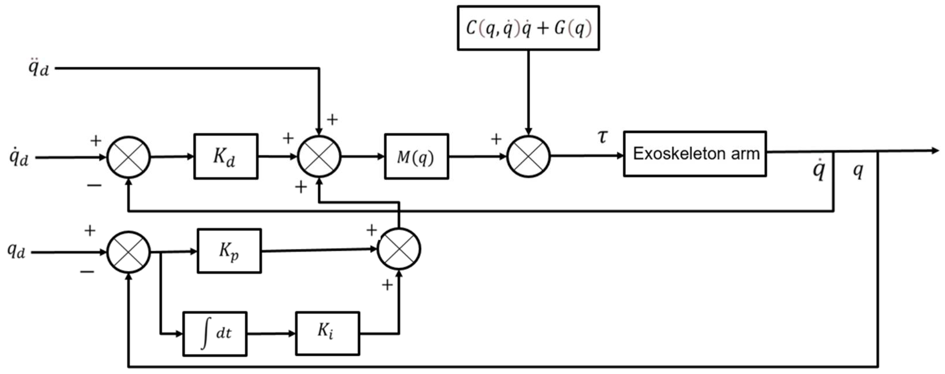
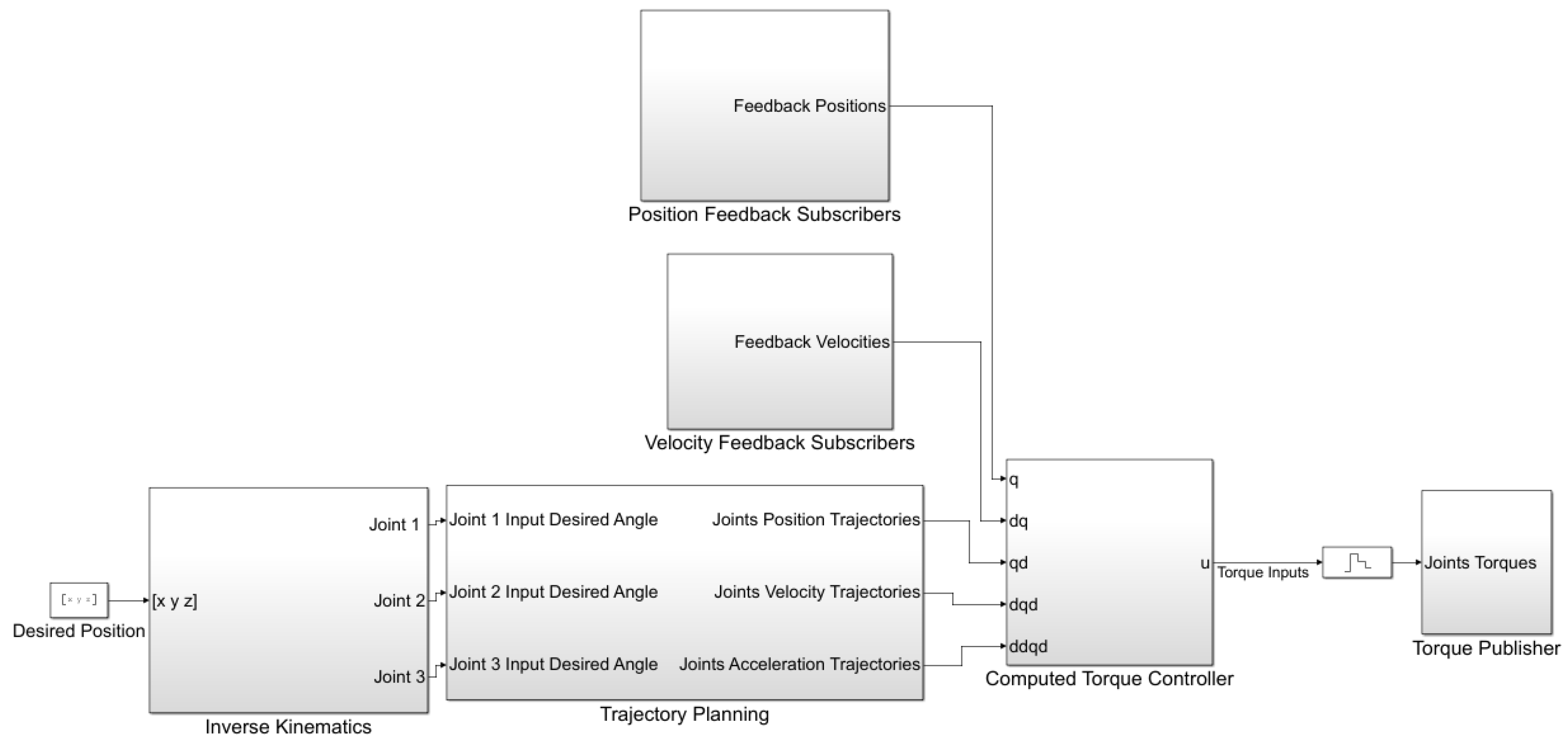
3.3. PID Computed Torque Control

The derived dynamic model that is described in Section 3.2 paved the way to implement the CTC on the SAMA exoskeleton. The dynamic modeling equation that describes the system dynamics is shown in Equation 7. In order to track a desired joint trajectory with the desired position q d , velocity q ˙ d , and acceleration q ¨ d , the computed torque controller calculated the torque that was needed to obtain a given configuration and velocity, provided the robot dynamics variables M ( q ) q ¨ + C ( q , q ˙ ) + G ( q ) . For an accurate dynamic model and q ( 0 ) = q d ( 0 ) , q ˙ ( 0 ) = q ˙ d ( 0 ) , the trajectory tracking can be solved by:
M ( q d ) q ¨ d + C ( q d , q ˙ d ) q ˙ d + G ( q d ) = τ
Both Equations (7) and (9) are fulfilled by the same initial conditions of q and q d . This follows from the fact that differential equation solutions are unique in that q ( t ) = q d ( t ) for all t 0 , which is an open-loop control law and it is not robust. In order to avoid this, the robot’s current state was utilized in order to select the control input as feedback and the exoskeleton’s real trajectory converged with the desired trajectory. By canceling all of the nonlinearities and generating precisely the torque that was required to overcome the actuator’s inertia:
M ( q ) q d + C ( q , q ˙ ) q ˙ + G ( q ) = τ
By substituting this control law Equation (10) into the dynamic Equation (7), the following control law was obtained, in which the exoskeleton’s starting position and velocity match the desired position and velocity. As a result, the computed torque control model is:
M ( q ) ( q ¨ d + K d e ˙ + K p e + K i ε ) + C ( q , q ˙ ) q ˙ + G ( q ) = τ
where ε ( t ) is the integral of tracking error e ( t ) and K p , K d , and K i are the PID controller gains. A block diagram that describes the implementation of CTC on the SAMA exoskeleton is shown in Figure 13. The complete dynamic model of SAMA, in addition to the CTC model, is shown in Figure 14.

4. Hardware Selection

4.1. Motor Selection

The main actuator module unit for SAMA consists of a dual shaft motor and a gearbox. A dual-shaft DC motor was selected as the actuator for the three joints. The nominal torque of this motor was τ = 3.86   N . m . A harmonic drive was used for the gearbox selection. The harmonic drive gearbox was chosen because of its greater torque rating, repeatable torque, lightweight, and small moment of inertia. The selected gearbox provides a reduction ratio of 50/1, the maximum allowable value of average load torque is 31 N.m, and the allowable instantaneous maximum torque is 82 N.m. A high-performance motor controller was used which supplied 12 V to 24 V with a peak current of up to 120 A per motor. Moreover, it had three control modes: position control, velocity control, and current control. In this way, the selected actuator units met the recommended power, angular speed, and torque of the required daily life activities of the human arm joints.

4.2. Sensor Selection

A capacitive increment encoder was chosen for angular position/velocity feedback. It had an 8192 CPR resolution and an index pulse. Furthermore, a linear magnetic hall switch sensor module was used for the joint limits as a safety precaution. It used a known reference point. The actuator module units for both shoulder rotations (flexion/extension and abduction/adduction) are shown in Figure 15. All of the system components and their design housings are characterized by their compactness and lightweight. The actuator module’s dimensions were 50 mm × 50 mm × 74 mm and it weighed 1.6 kg.

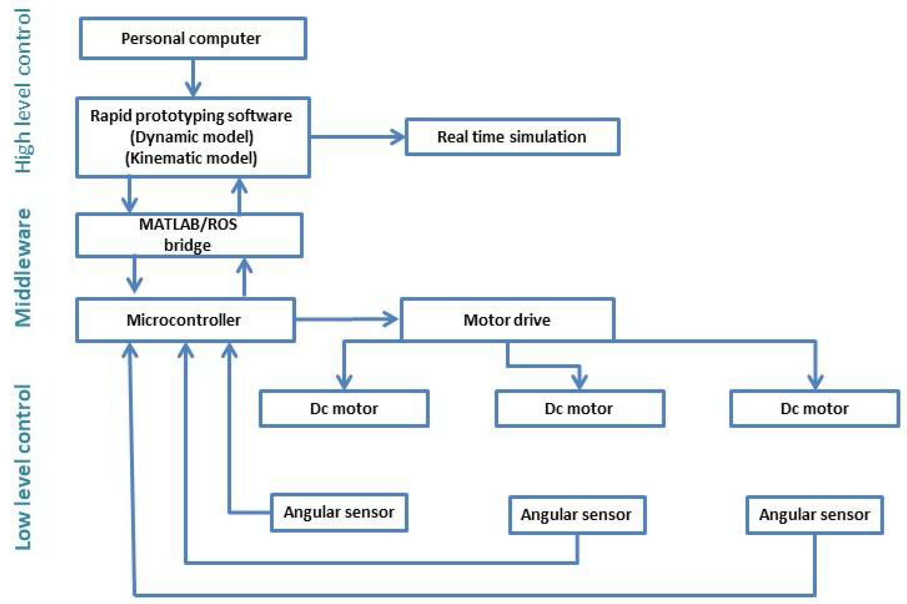
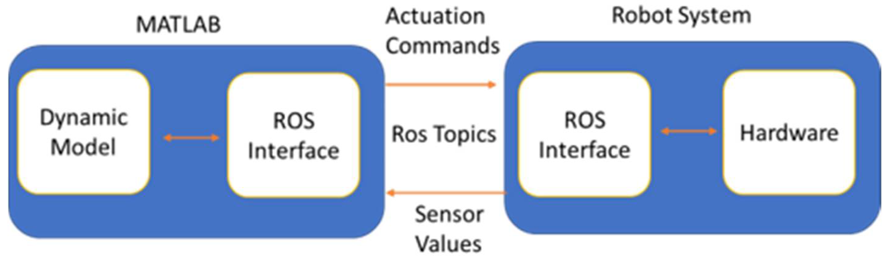
5. Control System Framework

A system control framework was developed for the SAMA exoskeleton. It mainly consists of two control layers: low-level and high-level. In addition, a user interface was developed for MATLAB–Simulink to respond to therapists’ decisions, decide on the plan of action, and aid subjects in completing rehabilitation tasks and exercises [42]. A low-level controller dealt with the actuator control and the position feedback. PID control was used to maintain the desired angles for the joints. A personal computer was used as the user interface, for system monitoring, kinematics calculations, real-time simulation, and hardware implementation. A middle layer existed between the previous two layers that included MATLAB–ROS bridge software. A diagram that describes the system control architecture is shown in Figure 16. The details of this framework will be discussed in the following subsections.

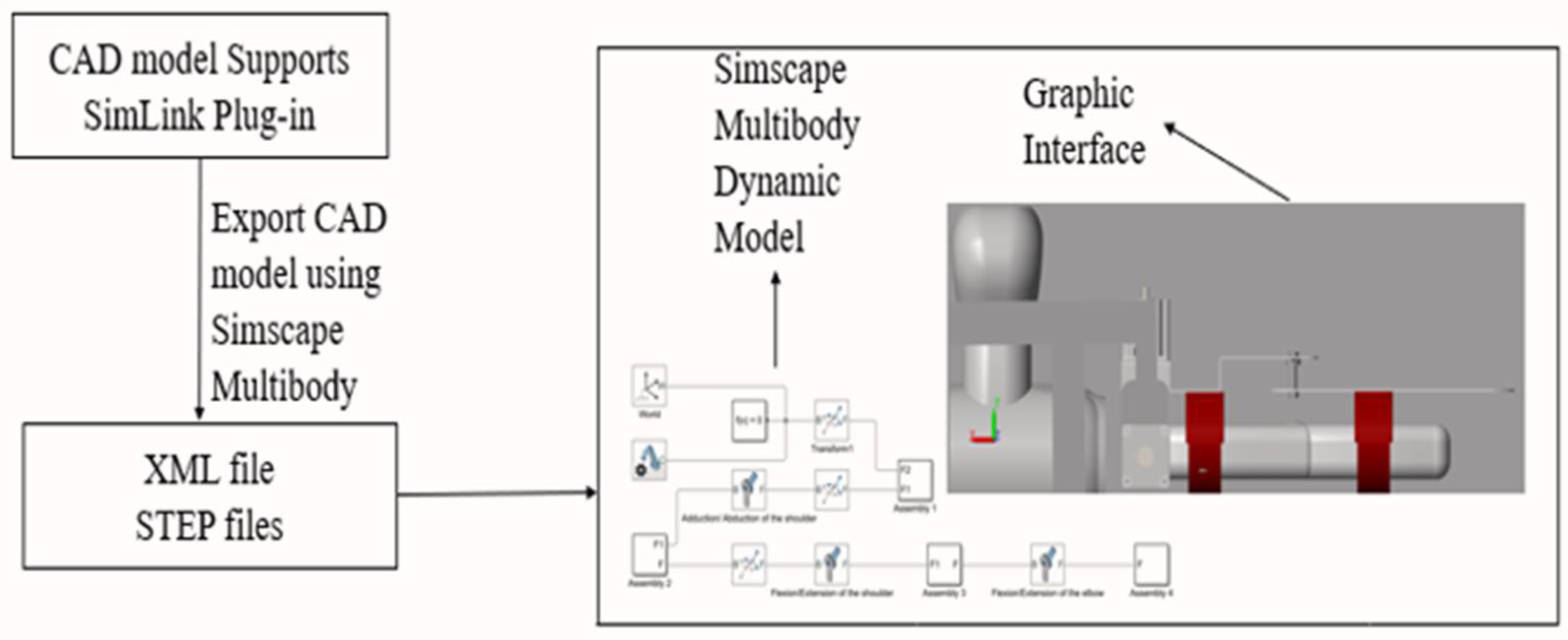
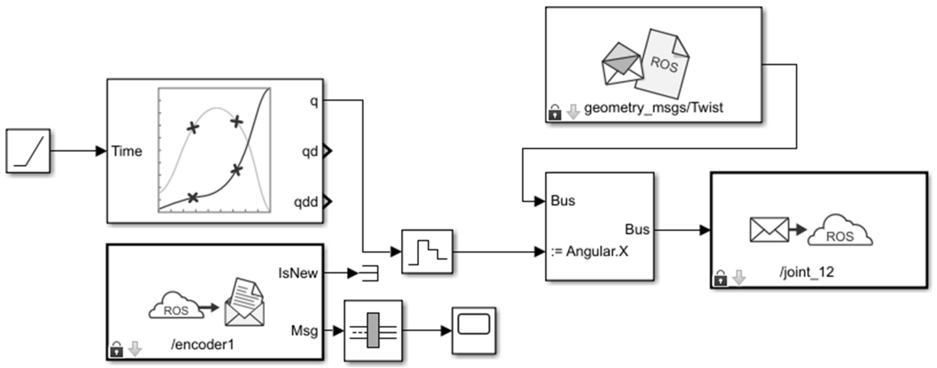
5.1. Rapid Prototyping Software

Rapid prototyping software has been developed for model simulation, real-time testing, and control method implementation. In supplement to the exoskeleton dynamic model that is discussed in Section 3, the dynamic model of the actuator modules was added. The DC motor model with its harmonic drive is shown in Figure 17 and a PID controller was added for angular position control. The step responses for the shoulder abduction/adduction and shoulder flexion/extension joints are shown in Figure 18a,b, respectively. The resultant simulation responses of the dynamic model joints are shown in Table 6.

5.2. Middleware

In order to provide robust and real-time prototyping between the system control layers, Robot Operating System (ROS) was chosen as the middleware interface for controlling the system motors and acquiring the sensor’s feedback [43]. In order to incorporate the system dynamics and control methods that were developed in the high-level controller, the MATLAB bridge was added to the ROS network so as to connect the low-level hardware components with the high-level layer. The communication between the system layers was carried out using ROSSERIAL. A diagram that describes the ROS–MATLAB middleware is shown in Figure 19.
Subscriber nodes were added to relay the desired positions of the high-level controller and send them to the motor. Similarly, other nodes were running, which received all of the sensor readings from the low-level controller. ROS enabled communication amongst the devices that were working for the same master and MATLAB acted as a node under its command. ROS nodes were added to the developed dynamic model and are shown in Figure 20.
Primary validation trials were performed for the developed framework on the SAMA exoskeleton. For safety precautions, the control system architecture was tested freely without a human subject at first. The maximum speed was fixed at 0.3 rad/s and could be modified by the user at any time. The achieved workspace for SAMA was a dexterous workspace and it is shown in Figure 21. There are two types of comparable workspaces. The first one is the reachable workspace, which is the region that the end effector can reach with at least one orientation. The second one is the dexterous workspace; this is a subspace of the reachable workspace and it allows several orientations of the end-effector pose. A dexterous workspace always guarantees flexible and smooth movements of the arm exoskeleton [44].

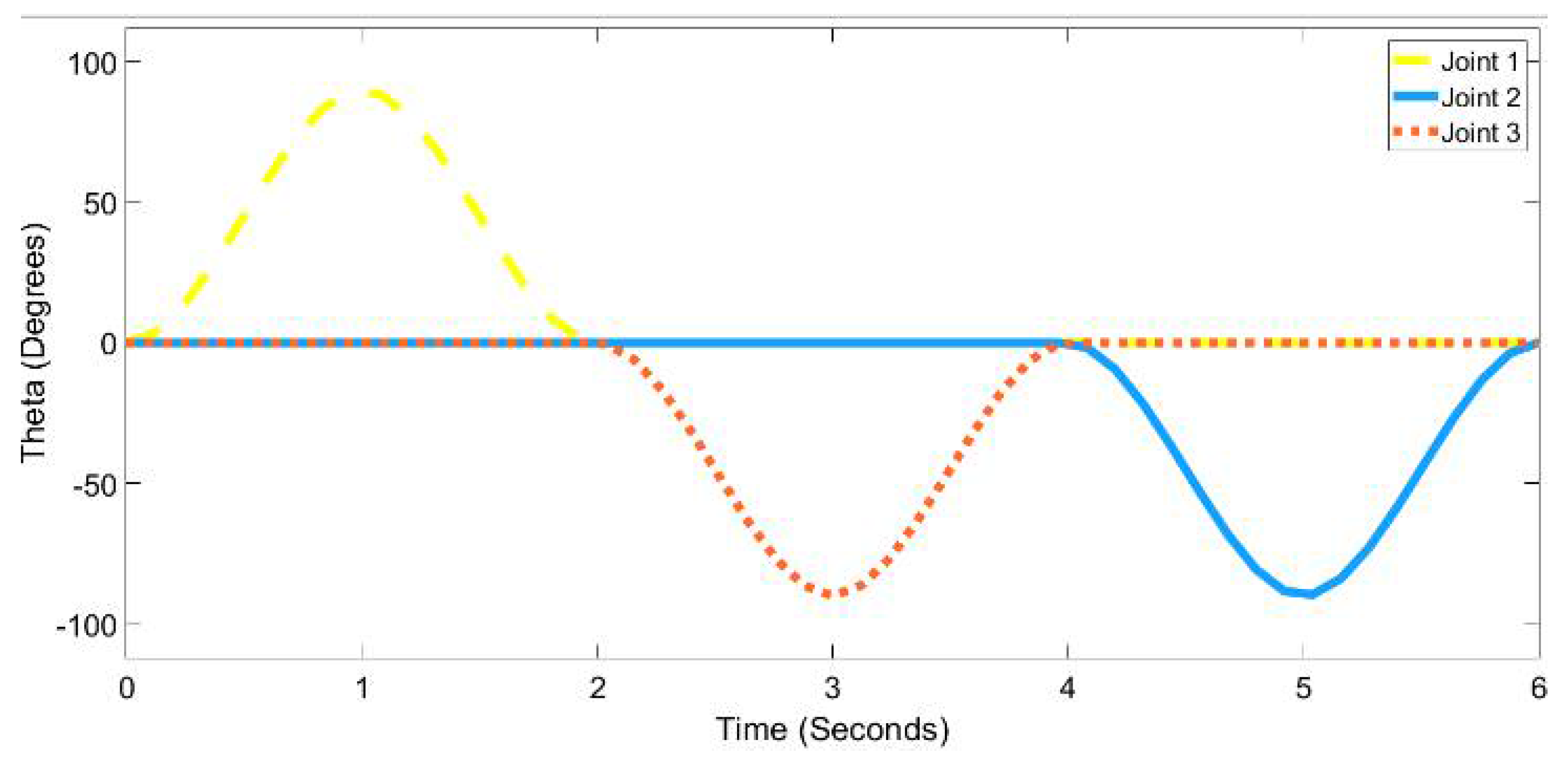
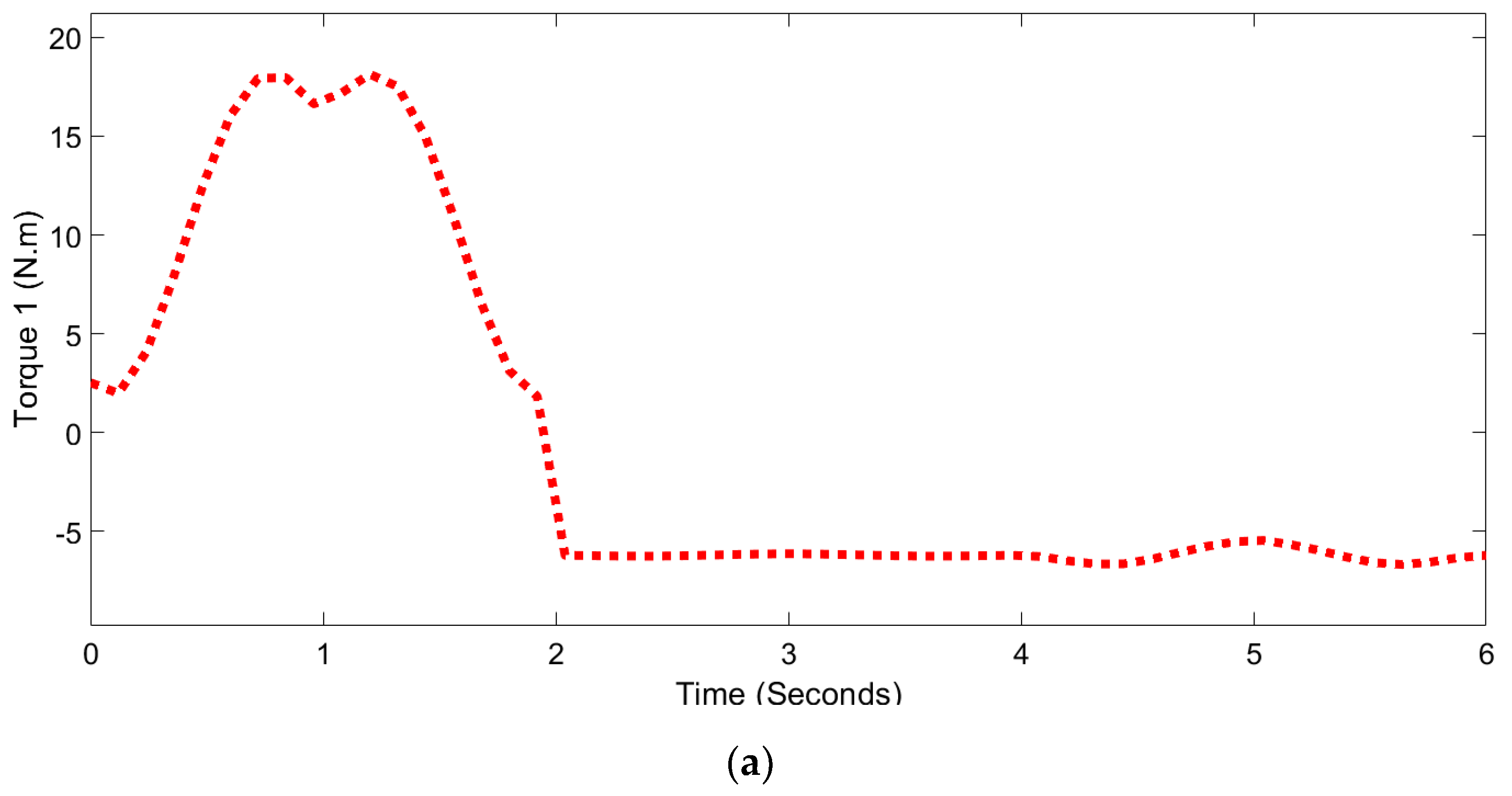
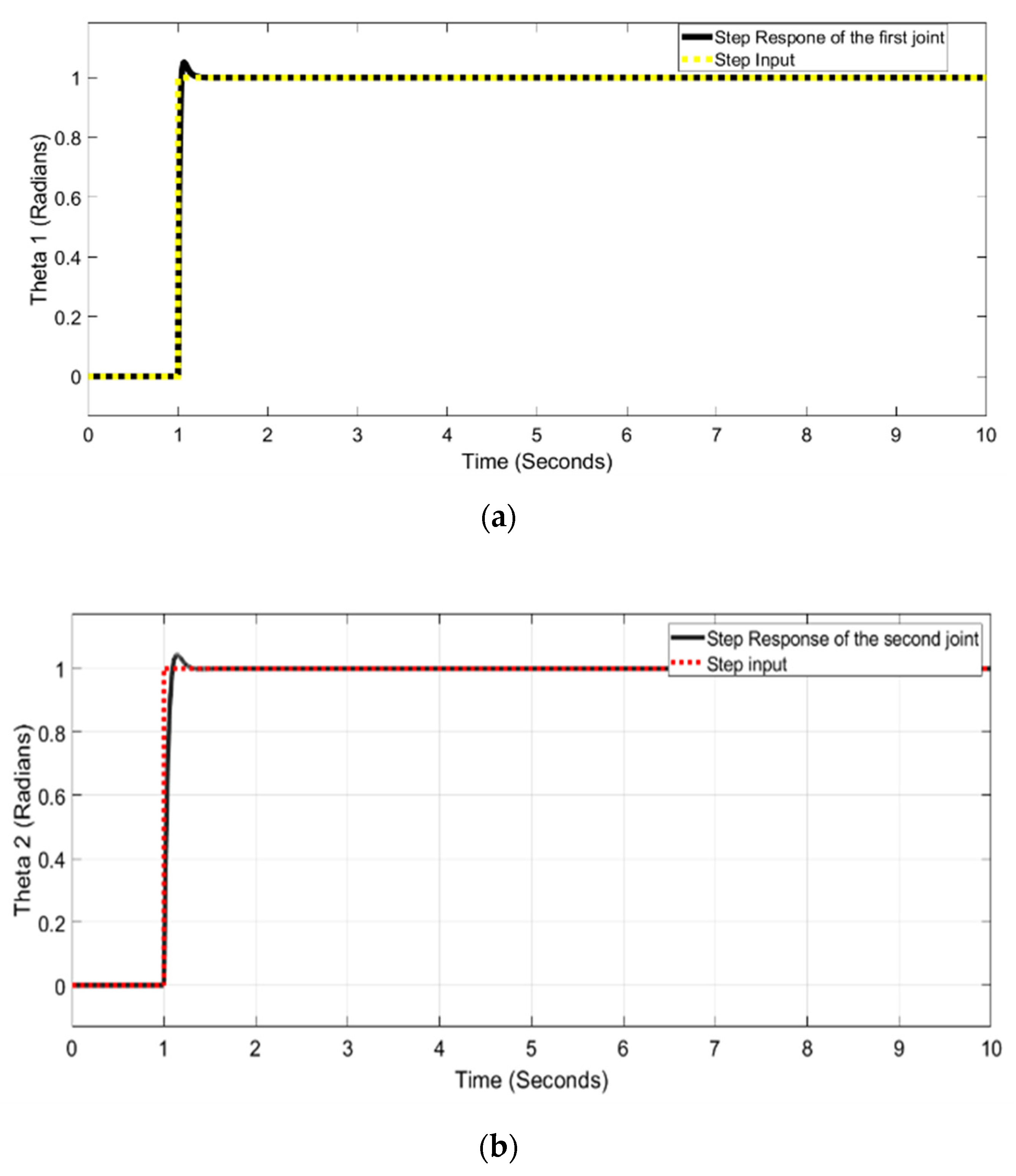
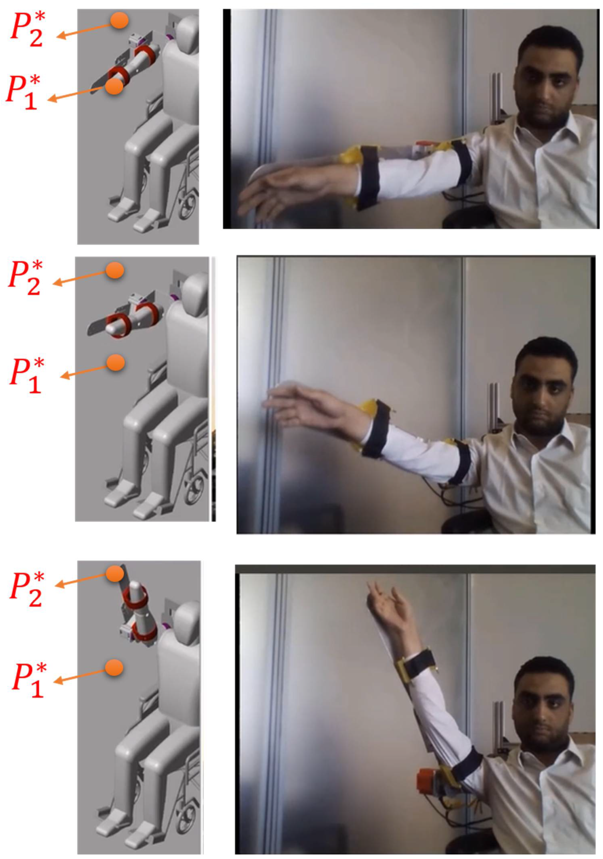
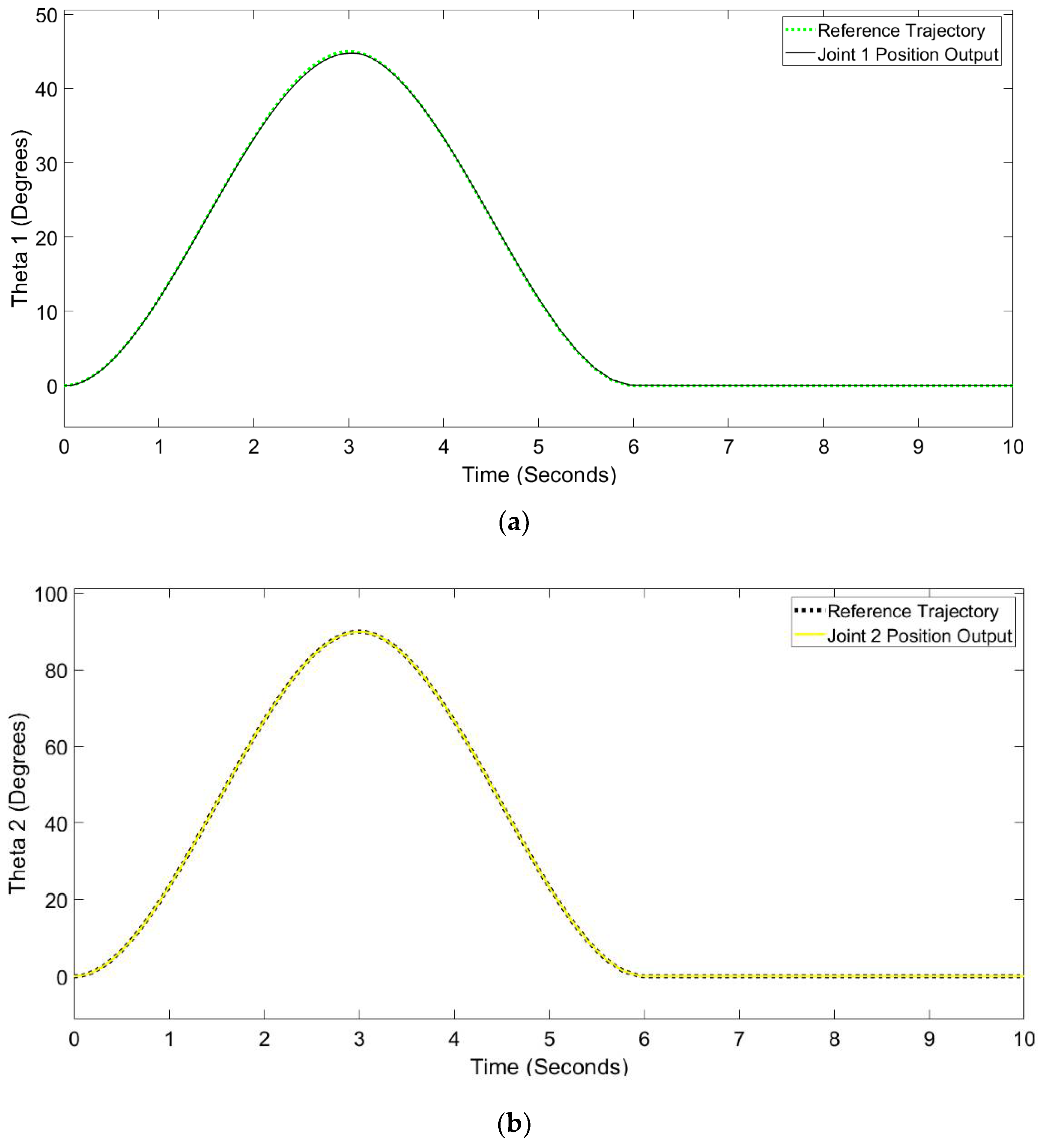
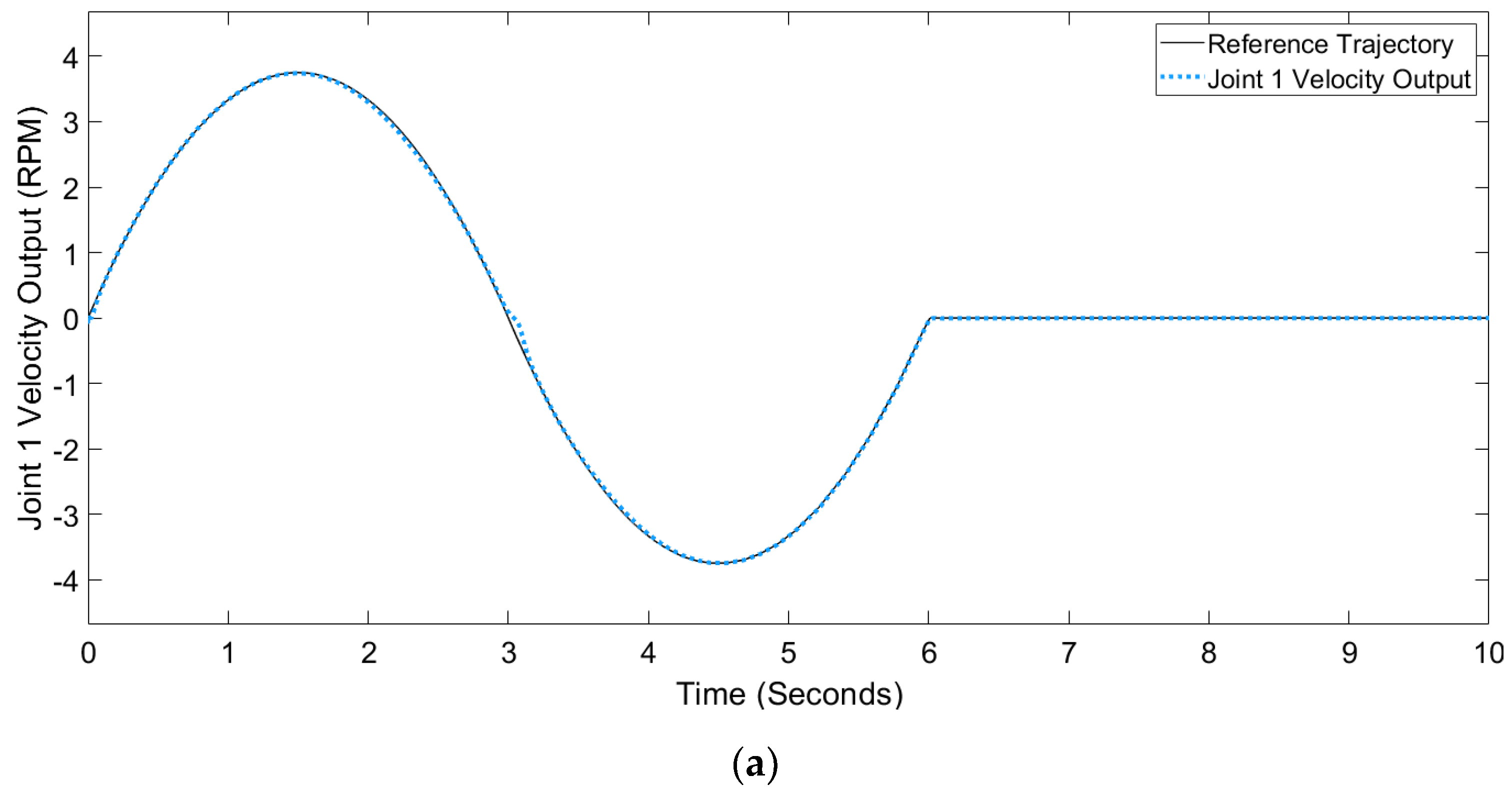
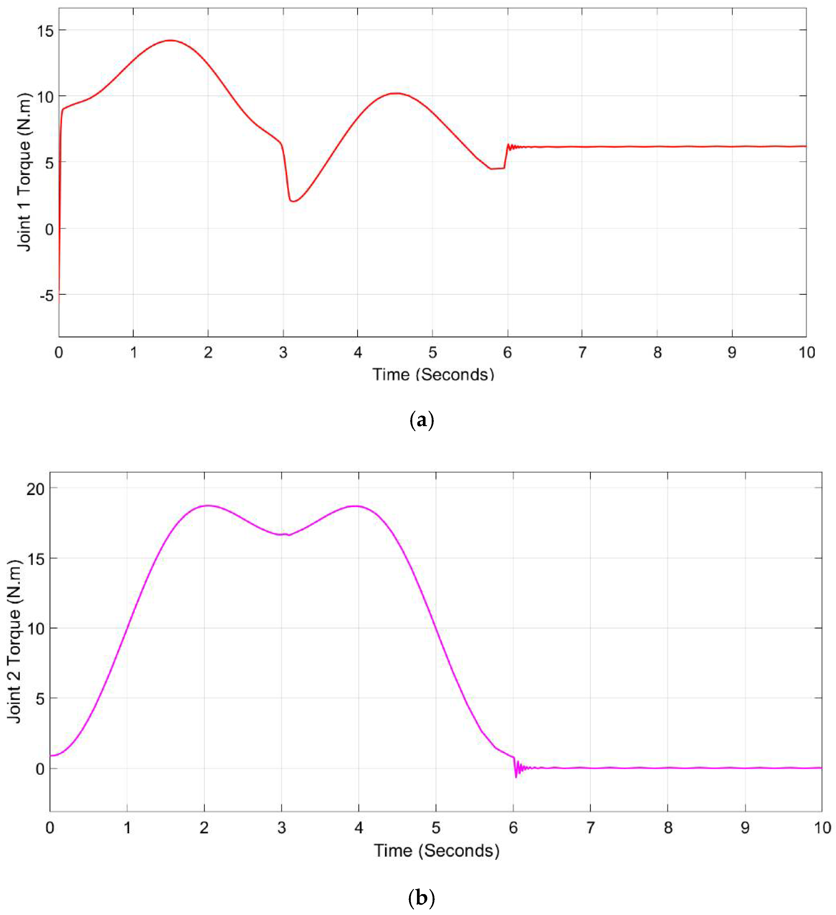
6. Experimental Results and System Evaluation

The prototype SAMA exoskeleton was tested with a human subject in order to check the joint movements, torque, developed control framework, and system responses. Two joints were utilized in the experimental work: shoulder A/A θ 1 and shoulder F/E θ 2 . The required trajectories were those which enabled the human subject to move their arm from coordinate P 1 to P 2 and back to P 1 . Cubic polynomial algorithms were utilized for the robot’s trajectory planning with controlled parameters. The starting pose of the robot was transformed into the corresponding joint angles by inverse kinematics calculations, which were done on the high control layer in order to obtain the trajectory in joint space.
For each joint whose motion was planned individually, the trajectories were published to the controller at the low control level and, at the same time, to the dynamic model. The full dynamic model with the middleware nodes in addition to the computed torque controller is shown in Figure 22. The SAMA exoskeleton was tested with a healthy subject (31 years old, measuring 1.85 m tall, and weighing 80 kg). Screenshots for the experimental testing are shown in Figure 23 wherein both shoulder joints F/E and A/A were tested against the desired trajectory.
The experimental trajectory tracking has shown that θ 1 and θ 2 have followed the desired trajectory with a maximum angle of 45° and 90°, respectively, as can be seen in Figure 24. The output steady state position error was 0.25° for θ 1 and 0.05° for θ 2 . Moreover, the velocity responses to the same trajectory are shown in Figure 25 where the joints exhibited a maximum velocity of 3.82 rpm and 7.48 rpm for joints 1 and 2, respectively. Additionally, the maximum generated torques were 14.19 N.m for θ 1 and 18.73 N.m for θ 2 ; these are displayed in Figure 26.
From the obtained experimental results, the proposed control technique has provided good tracking performance with finite-time convergence. The experimental dynamic responses to the SAMA exoskeleton are shown in Table 7.
In order to evaluate the obtained results, the results were compared to the responses of similar exoskeletons named Harmony upper body exoskeleton [45], Gravity balanced exoskeleton [46], NEURO-Exos elbow module [47], EAsoftM [48], MIT-MANUS [49], and ORTE [50]. SAMA’s joint responses were found to be as robust as the aforementioned exoskeletons. The details of this comparison are shown in Table 8.

7. Conclusions and Future Work

In this paper, the details of a new lightweight and compact rehabilitation exoskeleton named SAMA that was developed for the shoulder-arm complex are described. The biomechanics of a healthy human subject were studied and these data were used for the mechanical design of the exoskeleton’s structure, DOF, and ROM. The kinematics and dynamics of the exoskeleton were calculated in order to pave the way for the implementation of control schemes. A PID-CTC technique was used for SAMA, wherein a complete control architecture was developed for this system, which consisted of two main layers in addition to the middleware communication layer. The high-level controller was rapid prototyping software that was also an interface for the user. Desired trajectories and different control strategies can be added in this layer wherein the output can be shown in real-time simulation or real-time hardware testing. The low-level controller was concerned with the actuator’s control and sensory feedback. Between those two layers, a middleware layer was added so as to handle the communication between the layers and ensure robustness and accurate control; this was based on a MATLAB–ROS bridge. The system was tested experimentally through the actuation of two shoulder joints along a planned trajectory. The output responses of the shoulder joints showed high accuracy and responsiveness as the steady state error for θ 1 was 0.25° and 0.05° for θ 2 . The output generated torques were 14.19 N.m and 18.73 N.m for joint 1 and joint 2, respectively, which are sufficient torques for the aforementioned joints. The dynamic responses were calculated and were found to be comparable to those of other rehabilitation exoskeletons that are mentioned in the literature.
The promising results that were obtained for this prototype encourage several research efforts in the future. Additional DOF are expected to be added so as to emulate the human arm and provide more dexterity in rehabilitation exercises during therapy. Furthermore, more sensors, such as electromyography (EMG) sensors, are planned to be added to the system in further development in order to enhance the control loops and provide comprehensive information about the muscle signals and the exerted effort during actuation. The developed control framework was mainly tested for a PID-CTC controller of the joints. Additional force/torque controllers are planned to be implemented in forthcoming research in order to broaden the usage of the exoskeleton against different loads. Several adaptive and machine learning-based controllers are planned for implementation in further research for better control responses against several subjects with different biomedical parameters and different loads.

Author Contributions

Conceptualization: A.A.; Data curation: M.A.; Investigation: I.M. and M.M.H.; Methodology: A.A. and M.M.H.; Software: M.A. and I.M.; Supervision: M.M.H.; Validation: I.M.; Visualization: M.A. and A.A.; Writing—original draft: M.A., I.M. and A.A.; Writing—review & editing: M.M.H. All authors have read and agreed to the published version of the manuscript.

Funding

This research received no external funding.

Institutional Review Board Statement

Not applicable.

Informed Consent Statement

Not applicable.

Data Availability Statement

Not applicable.

Conflicts of Interest

The authors declare that there is no conflict of interest regarding this manuscript.

References

  1. Babaiasl, M.; Mahdioun, S.H.; Jaryani, P.; Yazdani, M. A review of technological and clinical aspects of robot-aided rehabilitation of upper-extremity after stroke. Disabil. Rehabil. Assist. Technol. 2015, 11, 1–18. [Google Scholar] [CrossRef]
  2. Alrabghi, L.; Alnemari, R.; Aloteebi, R.; Alshammari, H.; Ayyad, M.; Ibrahim, M.A.; Alotayfi, M.; Bugshan, T.; Alfaifi, A.; Aljuwayd, H. Stroke types and management. Int. J. Community Med. Public Health 2018, 5, 3715. [Google Scholar] [CrossRef]
  3. Owolabi, M.O.; Thrift, A.G.; Martins, S.C.O.; Johnson, W.; Pandian, J.D.; Abd-Allah, F.; Varghese, C.; Mahal, A.; Yaria, J.; Phan, H.T.; et al. The state of stroke services across the globe: Report of World Stroke Organization–World Health Organization surveys. Int. J. Stroke 2021, 16, 889–901. [Google Scholar] [CrossRef] [PubMed]
  4. Abd-Allah, F.; Moustafa, R.R. Burden of Stroke in Egypt: Current Status and Opportunities. Int. J. Stroke 2014, 9, 1105–1108. [Google Scholar] [CrossRef]
  5. Mehdi, H.; Boubaker, O. Stiffness and Impedance Control Using Lyapunov Theory for Robot-Aided Rehabilitation. Int. J. Soc. Robot. 2012, 4, 107–119. [Google Scholar] [CrossRef]
  6. Marchal-Crespo, L.; Reinkensmeyer, D.J. Review of control strategies for robotic movement training after neurologic injury. J. Neuroeng. Rehabil. 2009, 6, 20. [Google Scholar] [CrossRef]
  7. Lum, P.; Burgar, C.; Shor, P. Evidence for improved muscle activation patterns after retraining of reaching movements with the MIME robotic system in subjects with post-stroke hemiparesis. IEEE Trans. Neural Syst. Rehabil. Eng. 2004, 12, 186–194. [Google Scholar] [CrossRef]
  8. Raslan, M.; Abdellatif, A.; Atia, M.R.A. A novel exoskeleton finger mechanism for robotic applications. In Proceedings of the 2021 3rd Novel Intelligent and Leading Emerging Sciences Conference (NILES), Giza, Egypt, 23–25 October 2021; pp. 5–10. [Google Scholar] [CrossRef]
  9. Stinear, C.M.; E Lang, C.; Zeiler, S.; Byblow, W.D. Advances and challenges in stroke rehabilitation. Lancet Neurol. 2020, 19, 348–360. [Google Scholar] [CrossRef]
  10. Garcia, D.A.; Arredondo, R.; Morris, M.; Tosunoglu, S. A Review of Rehabilitation Strategies or Stroke Recovery. Early Career Tech. J. 2012, 11, 9. [Google Scholar]
  11. Jung, M.; Ludden, G. What Do Older Adults and Clinicians Think About Traditional Mobility Aids and Exoskeleton Technology? ACM Trans. Human-Robot Interact. 2019, 8, 1–17. [Google Scholar] [CrossRef] [Green Version]
  12. Pérez-Rodríguez, R.; Rodríguez, C.; Costa, Ú.; Cáceres, C.; Tormos, J.M.; Medina, J.; Gómez, E.J. Anticipatory assistance-as-needed control algorithm for a multijoint upper limb robotic orthosis in physical neurorehabilitation. Expert Syst. Appl. 2014, 41, 3922–3934. [Google Scholar] [CrossRef]
  13. Mohebbi, A. Human-Robot Interaction in Rehabilitation and Assistance: A Review. Curr. Robot. Rep. 2020, 1, 131–144. [Google Scholar] [CrossRef]
  14. Anam, K.; Al-Jumaily, A.A. Active Exoskeleton Control Systems: State of the Art. Procedia Eng. 2012, 41, 988–994. [Google Scholar] [CrossRef]
  15. López-Méndez, S.; Martínez-Tejada, H.V.; Valencia-García, M.F. Development of an armored upper limb exoskeleton. Revista Facultad de Ingeniería Universidad de Antioquia 2020, 95, 109–117. [Google Scholar] [CrossRef]
  16. Crouch, I.G. Introduction to Armour Materials in The Science of Armour Materials; Crouch, I.G., Ed.; Elsevier: Amsterdam, The Netherlands, 2016; pp. 1–54. [Google Scholar]
  17. Qassim, H.M.; Hasan, W.Z.W. A Review on Upper Limb Rehabilitation Robots. Appl. Sci. 2020, 10, 6976. [Google Scholar] [CrossRef]
  18. Sebastian, G.; Li, Z.; Tan, Y.; Oetomo, D. Force Observer for an Upper Limb Rehabilitation Robotic Device Using Iterative Learning Control. In Proceedings of the 2019 12th Asian Control Conference, Kitakyushu, Japan, 9–12 June 2019; p. 6. [Google Scholar]
  19. Gull, M.A.; Bai, S.; Bak, T. A Review on Design of Upper Limb Exoskeletons. Robotics 2020, 9, 16. [Google Scholar] [CrossRef]
  20. Kim, S.; Nussbaum, M.A.; Esfahani, M.I.M.; Alemi, M.M.; Jia, B.; Rashedi, E. Assessing the influence of a passive, upper extremity exoskeletal vest for tasks requiring arm elevation: Part II-“Unexpected” effects on shoulder motion, balance, and spine loading. Appl. Ergon. 2018, 70, 323–330. [Google Scholar] [CrossRef]
  21. Young, A.J.; Ferris, D.P. State of the Art and Future Directions for Lower Limb Robotic Exoskeletons. IEEE Trans. Neural Syst. Rehabil. Eng. 2017, 25, 171–182. [Google Scholar] [CrossRef]
  22. Vélez-Guerrero, M.A.; Callejas-Cuervo, M.; Mazzoleni, S. Design, Development, and Testing of an Intelligent Wearable Robotic Exoskeleton Prototype for Upper Limb Rehabilitation. Sensors 2021, 21, 5411. [Google Scholar] [CrossRef]
  23. Manjaree, S.; Thomas, M. Modeling of Multi-DOF Robotic Manipulators using Sim-Mechanics Software. Indian, J. Sci. Technol. 2016, 9, 1–7. [Google Scholar] [CrossRef] [Green Version]
  24. Gull, M.A.; Thoegersen, M.; Bengtson, S.H.; Mohammadi, M.; Andreasen Struijk, L.N.S.; Moeslund, T.B.; Bak, T.; Bai, S. A 4-DOF Upper Limb Exoskeleton for Physical Assistance: Design, Modeling, Control and Performance Evaluation. Appl. Sci. 2021, 11, 5865. [Google Scholar] [CrossRef]
  25. Birouaș, F.I.; Țarcă, R.C.; Dzitac, S.; Dzitac, I. Preliminary Results in Testing of a Novel Asymmetric Underactuated Robotic Hand Exoskeleton for Motor Impairment Rehabilitation. Symmetry 2020, 12, 1470. [Google Scholar] [CrossRef]
  26. Baud, R.; Manzoori, A.R.; Ijspeert, A.; Bouri, M. Review of control strategies for lower-limb exoskeletons to assist gait. J. Neuroeng. Rehabil. 2021, 18, 1–34. [Google Scholar] [CrossRef] [PubMed]
  27. Caballero, A. Advanced Rapid Control Prototyping System for Exoskeleton and Mechatronic Devices. Ph.D. Thesis, University Carlos III of Madrid, Madrid, Spain, 2014. [Google Scholar]
  28. Meng, W.; Liu, Q.; Zhou, Z.; Ai, Q.; Sheng, B.; Xie, S. Recent development of mechanisms and control strategies for robot-assisted lower limb rehabilitation. Mechatronics 2015, 31, 132–145. [Google Scholar] [CrossRef]
  29. Nguyen-Tuong, D.; Peters, J. Learning Robot Dynamics for Computed Torque Control Using Local Gaussian Processes Regression. In Proceedings of the 2008 ECSIS Symposium on Learning and Adaptive Behaviors for Robotic Systems (LAB-RS), Edinburgh, UK, 6–8 August 2008; pp. 59–64. [Google Scholar] [CrossRef]
  30. Hasan, S.; Dhingra, A.K. Development of a model reference computed torque controller for a human lower extremity exoskeleton robot. Proc. Inst. Mech. Eng. Part I J. Syst. Control. Eng. 2021, 235, 1615–1637. [Google Scholar] [CrossRef]
  31. Sharkawy, A.-N.; Koustoumpardis, P.N. Dynamics and Computed-Torque Control of a 2-DOF manipulator: Mathematical Analysis. Int. J. Adv. Sci. Technol. 2019, 28, 13. [Google Scholar]
  32. Gupta, A.; Mondal, A.K.; Gupta, M.K. Kinematic, Dynamic Analysis and Control of 3 DOF Upper-limb Robotic Exoskeleton. J. Eur. Des Systemes Autom. 2019, 52, 297–304. [Google Scholar] [CrossRef]
  33. Falkowski, P. Light Exoskeleton Design with Topology Optimisation and FEM Simulations for FFF Technology. J. Autom. Mob. Robot. Intell. Syst. 2022, 15, 14–19. [Google Scholar] [CrossRef]
  34. Dosoftei, C.-C.; Popovici, A.-T.; Sacaleanu, P.-R.; Gherghel, P.-M.; Budaciu, C. Hardware in the Loop Topology for an Omnidirectional Mobile Robot Using Matlab in a Robot Operating System Environment. Symmetry 2021, 13, 969. [Google Scholar] [CrossRef]
  35. Riani, A. Control and observation of exoskeleton for upper limb functional rehabilitation. Ph.D. Thesis, Paris-Saclay University, Paris, France, 2018. [Google Scholar]
  36. Leal-Naranjo, J.A.; Ceccarelli, M.; Miguel, C.R.T.S. Mechanical Design of a Prosthetic Human Arm and its Dynamic Simulation. In Advances in Robot Design and Intelligent Control, 540; Rodić, A., Borangiu, T., Eds.; Springer International Publishing: Cham, Switzerland, 2017; pp. 482–490. [Google Scholar] [CrossRef]
  37. Couvertier, M.; Monnet, T.; Lacouture, P. Identification of Human Body Segment Inertial Parameters. In Proceedings of the 22nd Congress of the European Society of Biomechanics, Lyon, France, 10–13 July 2016. [Google Scholar]
  38. Wang, X.; Song, Q.; Wang, X.; Liu, P. Kinematics and Dynamics Analysis of a 3-DOF Upper-Limb Exoskeleton with an Internally Rotated Elbow Joint. Appl. Sci. 2018, 8, 464. [Google Scholar] [CrossRef]
  39. Blanco-Ortega, A.; Vázquez-Sánchez, L.; Adam-Medina, M.; Colín-Ocampo, J.; Abúndez-Pliego, A.; Cortés-García, C.; García-Beltrán, C.D. A Robust Controller for Upper Limb Rehabilitation Exoskeleton. Appl. Sci. 2022, 12, 1178. [Google Scholar] [CrossRef]
  40. Gonzalez-Garcia, A.; Castañeda, H. Adaptive Integral Terminal Sliding Mode Control for an Unmanned Surface Vehicle Against External Disturbances. IFAC-PapersOnLine 2021, 54, 202–207. [Google Scholar] [CrossRef]
  41. Gasperina, S.D.; Ghonasgi, K.; de Oliveira, A.C.; Gandolla, M.; Pedrocchi, A.; Deshpande, A. A Novel Inverse Kinematics Method for Upper-Limb Exoskeleton under Joint Coordination Constraints. In Proceedings of the 2020 IEEE/RSJ International Conference on Intelligent Robots and Systems (IROS), Las Vegas, NV, USA, 24 October 2020; pp. 3404–3409. [Google Scholar] [CrossRef]
  42. Ozkul, F.; Barkana, D.E. Upper-Extremity Rehabilitation Robot RehabRoby: Methodology, Design, Usability and Validation. Int. J. Adv. Robot. Syst. 2013, 10, 401. [Google Scholar] [CrossRef]
  43. Galli, M.; Barber, R.; Garrido, S.; Moreno, L. Path planning using Matlab-ROS integration applied to mobile robots. In Proceedings of the 2017 IEEE International Conference on Autonomous Robot Systems and Competitions (ICARSC), Coimbra, Portugal, 26–28 April 2017; pp. 98–103. [Google Scholar] [CrossRef]
  44. Hessinger, M.; Müller, R.; Werthschützky, R.; Pott, P. Tool Position Control of an Upper Limb Exoskeleton for Robot-Assisted Surgery∗∗This work was funded by the German Federal Ministry of Education and Research (ref. no. 16SV5773K). IFAC-PapersOnLine 2015, 48, 195–200. [Google Scholar] [CrossRef]
  45. Ghonasgi, K.; de Oliveira, A.C.; Shafer, A.; Rose, C.G.; Deshpande, A.D. Estimating the Effect of Robotic Intervention on Elbow Joint Motion. In Proceedings of the 2019 28th IEEE International Conference on Robot and Human Interactive Communication (RO-MAN), New Delhi, India, 14–18 October 2019; pp. 1–6. [Google Scholar]
  46. Wu, Q.; Wang, X.; Du, F. Development and analysis of a gravity-balanced exoskeleton for active rehabilitation training of upper limb. J. Mech. Eng. Sci. 2016, 230, 3777–3790. [Google Scholar] [CrossRef]
  47. Crea, S.; Cempini, M.; Mazzoleni, S.; Carrozza, M.C.; Posteraro, F.; Vitiello, N. Phase-II clinical validation of a powered exoskeleton for the treatment of elbow spasticity. Front. Neurosci. 2017, 11, 261. [Google Scholar] [CrossRef]
  48. Oguntosin, V.W.; Mori, Y.; Kim, H.; Nasuto, S.J.; Kawamura, S.; Hayashi, Y. Design and Validation of Exoskeleton Actuated by Soft Modules toward Neurorehabilitation—Vision-Based Control for Precise Reaching Motion of Upper Limb. Front. Neurosci. 2017, 11, 352. [Google Scholar] [CrossRef] [Green Version]
  49. Krebs, H.I.; Ferraro, M.; Buerger, S.P.; Newbery, M.J.; Makiyama, A.; Sandmann, M.; Lynch, D.; Volpe, B.T.; Hogan, N. Rehabilitation robotics: Pilot trial of a spatial extension for MIT-Manus. J. Neuroeng. Rehabil. 2004, 1, 5. [Google Scholar] [CrossRef]
  50. Destarac, M.A.; Cena, C.E.G.; García, J.; Espinoza, R.; Saltaren, R.J. ORTE: Robot for Upper Limb Rehabilitation. Biomechanical Analysis of Human Movements. IEEE Lat. Am. Trans. 2018, 16, 1638–1643. [Google Scholar] [CrossRef]
Figure 1. Anatomy of the human upper limb.
Designs 06 00080 g001
Figure 2. Human upper limb anatomical rotations: (a) shoulder flexion/extension; (b) shoulder abduction/adduction; (c) shoulder rotation; (d) shoulder flexion/extension; (e) wrist pronation/supination; (f) wrist flexion/extension; (g) wrist ulnar/radial.
Designs 06 00080 g002
Figure 3. (a) Geometric configuration of shoulder flexion/extension and elbow flexion/extension joint angles noted as θ 2 and θ 3 , respectively. (b) Geometric configuration of shoulder abduction/adduction joint angle noted as θ 1 .
Designs 06 00080 g003
Figure 4. SAMA exoskeleton CAD model.
Designs 06 00080 g004
Figure 5. Kinematic structure of SAMA exoskeleton.
Designs 06 00080 g005
Figure 6. A block diagram that describes how the physical model was generated in MATLAB–Simulink from the original CAD file.
Designs 06 00080 g006
Figure 7. Dynamic physical model of SAMA exoskeleton.
Designs 06 00080 g007
Figure 8. SAMA inverse kinematics model.
Designs 06 00080 g008
Figure 9. Free body diagram of SAMA exoskeleton arm.
Designs 06 00080 g009
Figure 10. Inverse dynamics model of SAMA exoskeleton.
Designs 06 00080 g010
Figure 11. Input signals to the inverse dynamic model of SAMA.
Designs 06 00080 g011
Figure 12. Simulation results: (a) shoulder abduction/adduction rotation output torque, (b) shoulder flexion/extension rotation output torque and (c) elbow flexion/extension rotation output torque.
Designs 06 00080 g012aDesigns 06 00080 g012b
Figure 13. Block diagram that describes the implementation of PID-CTC on SAMA exoskeleton.
Designs 06 00080 g013
Figure 14. The complete dynamic model of SAMA in addition to the PID-CTC model.
Designs 06 00080 g014
Figure 15. Actuator module unit for SAMA shoulder rotations. The CAD design is shown on the left (a), while the whole actuator module assembly is shown on the right (b).
Designs 06 00080 g015
Figure 16. Control architecture of the upper limb exoskeleton SAMA.
Designs 06 00080 g016
Figure 17. The dynamic model of the actuator module of the exoskeleton SAMA.
Designs 06 00080 g017
Figure 18. (a) Real-time step response of shoulder abduction/adduction rotation ( θ 1 ). (b) Real-time step response of shoulder flexion/extension rotation ( θ 2 ).
Designs 06 00080 g018
Figure 19. MATLAB–ROS communication diagram.
Designs 06 00080 g019
Figure 20. ROS nodes which were added in MATLAB–Simulink.
Designs 06 00080 g020
Figure 21. Different screenshots of the dexterous workspace for the arm exoskeleton SAMA.
Designs 06 00080 g021
Figure 22. SAMA exoskeleton high-level control software with middleware nodes and computed torque control.
Designs 06 00080 g022
Figure 23. The input trajectory drives the motors of the exoskeleton and the dynamic model simultaneously.
Designs 06 00080 g023
Figure 24. (a) Experimental position responses of shoulder joint A/A ( θ 1 ); (b) Experimental position responses of shoulder joint F/E ( θ 2 ).
Designs 06 00080 g024
Figure 25. (a) Experimental velocity responses of shoulder joint A/A ( θ 1 ); (b) Experimental velocity responses of shoulder joint F/E ( θ 2 ).
Designs 06 00080 g025aDesigns 06 00080 g025b
Figure 26. (a) Experimental torque responses of shoulder joint A/A ( θ 1 ); (b) Experimental torque responses of shoulder joint F/E ( θ 2 ).
Designs 06 00080 g026
Table 1. Bio-mechanical data of the test subject.
Body SegmentLength (mm)Range of Motion (°)
Hip–Shoulder [ L 4 ] 709.3-
Shoulder to Shoulder [ 2 × L 3 ] 420-
Shoulder–Elbow [ L 1 ] 244.8-
Elbow–Wrist [ L 2 ] 251.3-
Shoulder adduction/abduction [ θ 1 ] -−10 to 115
Shoulder flexion/extension [ θ 2 ] -−50 to 115
Elbow flexion/extension [ θ 3 ] -5 to 120
Table 2. DH parameters table for SAMA exoskeleton joints.
Link θ i d i α i a i
1 θ 1 L 1 90 ° 0
2 θ 2 L 2 0 L 3
3 θ 3 00 L 4
Table 3. ROM of SAMA exoskeleton joints compared to other upper limb exoskeletons.
PrototypeArticulationType of RotationROM (°)
SAMAShoulderExtension/Flexion170
Abduction/Adduction120
ElbowExtension/Flexion115
An armored upper limbShoulderExtension/Flexion225
Exoskeleton [15] Abduction/Adduction235
ULEL [26]ShoulderExtension/Flexion90
Abduction/Adduction-
3-DOF upper-limb exoskeleton [38]ShoulderExtension/Flexion130
Abduction/Adduction150
ElbowExtension/Flexion118
3-DOF upper extremity robot [39]ShoulderExtension/Flexion134
Abduction/Adduction180
ElbowExtension/Flexion135
Table 4. Mass of body segments as % of total body mass [15].
Body Segment% of Total Body Mass
Upper Arms5.31
Forearms3.64
Hands1.41
Table 5. Motor sizing for the joints of the SAMA exoskeleton.
Motor Peak   Torque   ( N . m ) RMS   Torque   ( N . m )
147.08.9
249.39.0
310.82.3
Table 6. Simulation dynamics responses of SAMA exoskeleton.
ExoJointOvershoot (%)Rise Time (ms) Settling Time (ms)SS Error (°)
SAMAShoulder A/A5.030.02630.130.0019
Shoulder F/E4.370.06360.2170.0024
Table 7. Experimental dynamic responses of SAMA exoskeleton.
ExoJointOvershoot (%)Rise Time (ms) SS Error (°)
SAMAShoulder A/A0.010.00350.25
Shoulder F/E0.0080.00230.05
Table 8. Comparison of SAMA exoskeleton against similar upper-limb exoskeletons.
ExoDOFActuation MethodObjective Type of Control
SAMA3 activeElectric with harmonic driveRehab.Real-time motion control via a ROS- MATLAB
approach
Harmony7 activeSeries electric with harmonic driveRehab.Trajectory tracking with impedance control
Gravity balance exoskeleton4 active
1 passive
Electric with a pulley systemRehab.Angular position control
NEURO-Exos3 active
2 passive
Electric with harmonic driveRehab.Angular position control
EAsoftM2 active
2 passive
Pneumatic actuatorsRehab.Visual-based control
MIT-MANUS2 activeElectric actuatorsGame-based exo. for rehab.Force control
ORTE6 activeElectric actuatorsRehab.Simulation-based position control
Publisher’s Note: MDPI stays neutral with regard to jurisdictional claims in published maps and institutional affiliations.

