Abstract
Despite the promising potential of the hybrid electric power-split layout, its broader market penetration is prevented by the large number of feasible solutions and the constructive complexity, which overcomplicate the design process. Moreover, due to the lack of relevant literature references, the power-split transmissions design is even more difficult if concerning applications outside the automotive and agricultural sectors. In this paper, a general parametric model already available in the literature to design a single-mode power-split transmission with up to two planetary gear sets and six ordinary gear sets was applied to hybridize an oil drilling rig to recover energy braking during the gravity-driven lowering phases. This is the first power-split electric hybridization of a drilling rig. Two solutions differing in engine power size are presented. Thanks to the modularity of the model, the procedure enabled the optimization of the ICE, the electric machines, and the gear sets through decoupled design phases.
1. Introduction
The shortage of fossil fuel reservoirs and the increasing level of greenhouse gases are driving engineers, scholars, and researchers toward more sustainable solutions than the traditional internal combustion engine (ICE) for energy production. The hybridization of the thermal powertrain is one of the most successful ways to save fuel and reduce emitted fumes [1]. The introduction of different propulsion systems in cooperation with the ICE allows the optimization of the engine operation and the possibility to store surplus energy provided by the ICE or recoverable from braking. Thanks to the recent advancements in battery technology and the reliability of electric machines, the hybrid electric powertrain is the preferred hybrid concept [2,3,4,5].
Besides the most common series and parallel hybrid electric layouts, the power-split technology has been widely used in the automotive and agricultural sectors [6,7]. The combined operation of two electric motor-generators (MGs) allows the ICE to rotate independently from the wheel speed and function within the most efficient range, just as in a series hybrid. However, the electromechanical energy conversions are minimized because part of the engine power can be mechanically transmitted to the final drive, as in a parallel hybrid. The battery pack can aid the thermal unit for vehicle propulsion or store surplus energy. The transmission system necessary to realize power-split operations is called the power-split unit (PSU) and consists of one or more planetary gear sets (PGs) and ordinary gear sets (OGs). Clutches and brakes can be deployed to vary the connections between transmission components and realize multimode operations.
Despite the apparent advantages of power-split transmissions, the considerable number of feasible solutions available in the design stage complicates their synthesis [8,9]. The graph theory [10] is the most common method adopted to carry out an automated synthesis of power-split transmissions. The powertrain structure is converted into abstract entities and numerical combinations to be introduced in optimization algorithms to search for all potential constructive arrangements [11,12,13,14,15,16,17]. Thus, a merely explorative approach is pursued, which enables the automatic generation of a broad design space. Nevertheless, this procedure often results in hundreds of billions of potential solutions [9]. Thus, it is apparent that the screening and selection of the best constructive layout cannot be effectively fulfilled by the designer alone, who instead should rely on computer-aided design techniques. An alternative approach for power-split transmissions design is based on the optimization of the most promising mature technologies available on the market [18,19,20,21]. However, this procedure is unsuitable to meet specific functional requirements, especially outside the automotive field, given the limited number of already implemented solutions.
This paper aims to highlight the potentiality of a unified parametric model for the functional design of power-split transmissions [22,23,24], which enables a hierarchical and modular procedure. The PSU can be modeled as a black box characterized by a few physically consistent functional parameters. In the analysis stage, these parameters can be identified from any constructive layout [24] and lead to a comprehensive analysis of the powertrain [25,26,27,28], which is essential for the implementation of a proper energy management strategy (EMS). In the design stage, the functional parameters can be defined before the synthesis of the constructive arrangement, according to the case-related design requirements. Their definition affects the power size of the electric machines and the kinematics of the PSU. Then, it is possible to synthesize the mechanical devices inside the PSU, prioritizing the selection of the PGs, which are more challenging to arrange so as to avoid constructive complexity and low efficiency. Lastly, the necessary OGs are synthesized to meet the kinematic requirements. This design procedure allows the designer to have complete control in all design phases, which are decoupled one from another so as to optimize the ICE, the electric machines, and the gear sets without any mutual interference.
The model was firstly proposed in [22], where a numerical example of a PSU design was provided. However, the ICE and electric machines’ sizing and operations were not considered. Additionally, the terminology and the mathematical treatment used in [22] were not aligned with those used in the analysis stage [24]. In [23], the parametric model was used to design an automotive power-split transmission. Now, the main contribution of this work is to apply the design method based on the parametric model proposed in the previous papers to a field never explored before for power-split hybridization. The rearranged mathematical equations of [24] for the PSU design are deployed to select the electric machines and synthesize the power-split transmission to hybridize an oil drilling rig for braking energy recovery. Two solutions differing in the ICE size are proposed.
Soil drilling is a very energy-consuming process [29], where the energy efficiency can be enhanced in several ways, including the improvement of the drill bit material [30], the implementation of a proper control strategy to increase the engine efficiency [31], and the embedding of an energy storage system to modulate the peak power requested to the engine [32,33,34]. In addition, the release of gravitational energy during the lowering phases of drilling, tripping in, and casing can be exploited by avoiding a completely dissipative braking but recovering the braking power hydraulically [35], mechanically [36], or electrically [37,38]. Nonetheless, as far as we know from our literature analysis, this is the first power-split electric hybridization of a drilling rig for this purpose.
The oil drilling rig used as a case study is described in Section 2, which also reports the main feature of the parametric model and the PSU design procedure. Section 3 shows the design procedure results and highlights the importance of the designer choices in each design phase. Section 4 discusses the design process and the results and suggests future developments of this work.
2. Methods
The design procedure described in the following section aims to select the best power-split transmission to fulfill some operative and constructive requirements, which are related to the operations of the system to hybridize and the availability of thermal and electric actuators. Nevertheless, these requirements can usually be identified before the transmission design process. Thus, this section begins with a description of the existing drilling rig to hybridize and its operations. Then, the hierarchical and modular procedure for designing the power-split transmission and the parametric model on which it is based are outlined.
2.1. Oil Drilling Rig under Study: Description and Operations
The oil drilling rig taken as a case study in this paper is the Drillmec MR-8000 [39]: a mobile self-propelled rig with a maximum static hook load of 200 tons and a maximum drilling depth of 3000 m. Since this paper aims to hybridize the drilling rig to recover braking energy, only the hoisting system is here described in more detail. However, it should be noted that other separately fed subsystems exist in the plant, such as the mud pumping system; the hydraulic top-drive providing the rotative drilling torque; and auxiliary equipment for lubrication, drill pipe handling, and casing pipe cementation.
The hoisting mechanism (Figure 1) relies on a drawworks, namely, a large winch that reels out and in the drilling line in a controlled fashion. The drilling line is winded on the crown block and the traveling block. The latter carries the top-drive and hook block that raises or lowers the drilling stem. The raising phases are powered by two diesel engines with 403 kW rated power each. The prime movers’ power flows combine together in an engine coupler and then in a chain box connected to the winch. The lowering phases are gravity-driven, and a brake system ensures the adequate descending speed of the drill stem. However, introducing an electric unit upstream of the drawworks would enable regenerative braking instead of dissipative friction braking to recover energy while the drill stem is lowered into the wellbore. Thus, our research aims to replace the diesel prime movers and the compound block with a hybrid electric power-split powertrain (Figure 1) to recover braking energy and reduce the thermal power needed thanks to the addition of the batteries as a further power source. Therefore, one design requirement of this work is to keep only one diesel ICE in the hybridized rig. Moreover, the power-split unit decouples the ICE speed from the winch speed; hence, the ICE can continuously operate in its most efficient range.
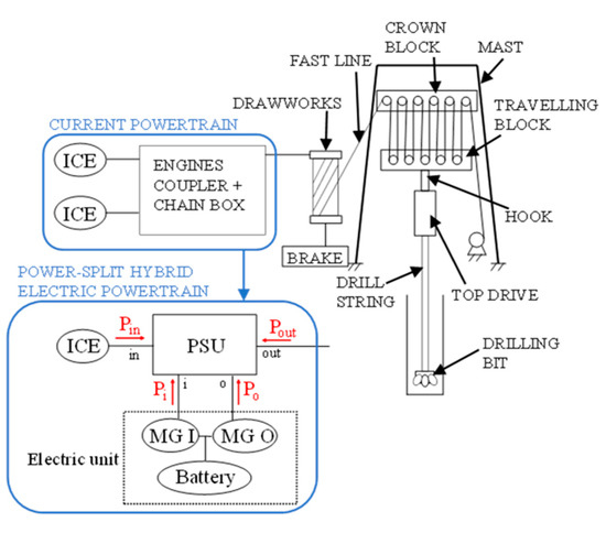
Figure 1.
Drillmec MR-8000 hoisting system and drawworks prime movers before and after hybridization. Red arrows show the PSU power positive sign.
To design the power-split transmission properly, it is essential to know the speed, torque, and power required on the output shaft. For this purpose, we simulated a 3000 m deep drilling with intermediate casing at 500, 1500, and 2500 m. The series of operations to perform to complete an intermediate casing are the following:
- DRILLING: the drill string is slowly lowered into the wellbore while the top-drive provides the drill bit with the torque to drill. When the drilling depth equals the drill string length, the drill string is blocked into the wellbore while the top-drive and hook block alone are raised to attach two more drill pipes and resume drilling.
- TRIP OUT: the top-drive and hook block are raised to pull out of the hole (POOH) the drill string. When a double stand of drill pipes comes out of the wellbore, it is removed from the top-drive and hook block, which then are lowered to lift the remaining drill string.
- CASING: a joint of two casing pipes is lowered into the wellbore; then, the top-drive and hook block are raised to pick up another joint and repeat the operation. When the casing pipes into the wellbore reach the bottom of the wellbore, they are cemented.
- TRIP IN: the drill string is run into the hole (RIH), starting from the drill collars, which are thicker than the drill pipes to provide the weight on the bit (WOB). When a double stand of drill collars or drill pipes is completely lowered into the wellbore, the top-drive and hook block are raised to pick up another double stand and repeat the operation until the drill string occupies the whole wellbore length. Then, the drilling phase can restart.
To simplify the analysis, we assumed a realistic constant speed for the top-drive and hook block in each phase, shown in Table 1 and derived from [29].

Table 1.
Top-drive and hook block speed in each phase.
The hook load was simulated by considering the weight of the hook, the top-drive, the casing pipes during the casing phase, and the drill collars and drill pipes during the tripping phases, reduced by the WOB and the buoyancy factor due to the immersion in drilling fluid during the drilling phase. The constructive parameters used in this analysis are reported in Table 2 and deduced from [29]. Any inertial effects or other disturbances were neglected.

Table 2.
Constructive parameters of the drill string.
From data in Table 1 and Table 2, the linear speed, force, and power on the hook can be assessed and then reduced in terms of rotational speed, torque, and power on the PSU output shaft. The results shown in Figure 2, Figure 3 and Figure 4 were obtained by considering the overall transmission ratio of 0.00800 m between the hook and the PSU output shaft and the overall efficiency of 0.845. From a simplified perspective, we omitted any bit trip for inspection and replacement of a worn or underperforming drill bit; nevertheless, it would have implied additional POOH and RIH phases during drilling.
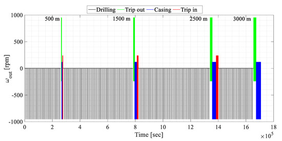
Figure 2.
PSU output shaft speed.
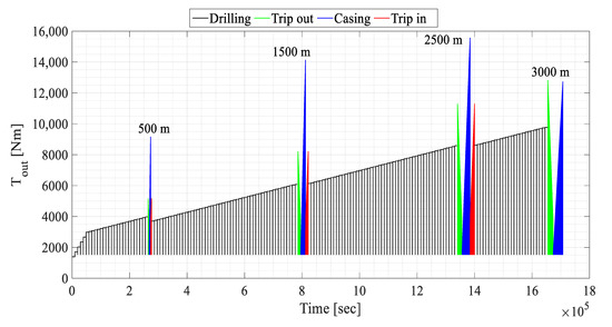
Figure 3.
PSU output shaft torque.
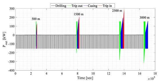
Figure 4.
PSU output shaft power.
2.2. Parametric Model for Power-Split Transmissions: A Modular Procedure for the Design
Power-split transmissions differ in the number and the arrangement of PGs, OGs, and clutches and brakes if multimode operations are available. A shunt power-split transmission consists of only one PG, while a compound PSU contains two or more PGs. However, despite the different constructive layout, any PSU can be modeled as a four-port black box connected to the ICE (by the in shaft), the output load (by the out shaft), and the electric machines MG I and MG O (by the i and o shafts, respectively) [22] (see Figure 1). In the shunt configuration, two of the four PSU main shafts have proportional speed; in particular, one electric machine (i or o shaft, alternatively) can rotate proportionally to the ICE or the output load, realizing an output-split or an input-split configuration, respectively. Moreover, the PSU can be modeled as a combination of three-port mechanisms (TPMs), consisting of one PG and up to three OGs (Figure 5). The PG branches (carrier, ring gear, and sun gear) are generically indicated by upper-case letters (X, Y, Z), while the PSU main ports (in, out, i, o) are indicated by lowercase letters (x, y, z).
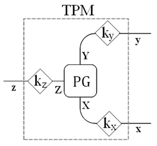
Figure 5.
Scheme of a three-port mechanism with one PG (rounded-corner square) and three OGs (rhombi) realizing the kj fixed ratio.
The design procedure proposed in [22] can be used for the functional design of a single-mode shunt and compound PSU with up to two TPMs. It relies on the parametric model described in [22,24] based on functional parameters that rule the speed, torque, and power relationships among the PSU shafts, thus fully characterizing the PSU behavior. These functional parameters are the nodal ratios and the corresponding speed ratios.
Assuming that
is the overall speed ratio between the PSU output and input shafts, the nodal ratio is the overall speed ratio achieved when the generic kth shaft is motionless:
Note that and by definition. The nodal ratios and are also called mechanical points.
Assuming that is the speed ratio between the jth PSU shaft and the input, the corresponding speed ratio is the speed ratio achieved when the generic kth shaft is motionless:
In the analysis stage, the known constructive arrangement of the mechanical devices inside the PSU leads to the identification of a univocal set of functional parameters [24]. Nonetheless, in the design stage, the same set of functional parameters matches several constructive solutions [22]. Therefore, pursuing a modular and hierarchical approach by decoupling the design phases is crucial to avoid mutual interferences between the actuator sizing and the gear sets synthesis while meeting the operative requirements. Hence, after identifying the system operating points, the functional parameters can be selected before synthesizing the PSU constructive arrangement. In particular, the selection of the mechanical points affects the electric machines’ power size and the PSU kinematics relations. The latter are used to synthesize the PGs constructive arrangement. Then, the corresponding speed ratios are selected to define the speed and torque ratios between the PSU ports. Lastly, the OGs necessary to meet the kinematics requirements are assessed.
In the following, the design procedure is described in detail:
- 5.
- IDENTIFICATION OF THE OVERALL SPEED AND POWER RATIOS: the operations of the ICE and the output load are defined to assess the overall speed ratio and the overall power ratio :
Given the positive power sign of Figure 1 and considering always that , the PSU provides power to the output if , while energy recovery may be realized if . Moreover, if , the power required in the output is higher than the ICE power; thus, the battery cooperates with the ICE to fulfill the output power demand. and are the independent variables ruling the addressed mathematical treatment.
- 6.
- MECHANICAL POINTS SELECTION AND ELECTRIC MACHINES’ POWER SIZE: the power flows of the electric machines ( and ) are ruled only by the mechanical points:
The previous equations show that operating at the mechanical point (or ) implies that the MG I (or MG O) power is null. Hence, choosing a long-lasting speed ratio as a mechanical point would reduce the electromechanical conversions and the related power losses by improving overall efficiency. This consideration along with Equations (5) and (6) allow the designer to prioritize the electric machines sizing by properly selecting the mechanical points upstream of the design process [22]. For example, selecting the combination of mechanical points that minimizes the electric machine rated power could be particularly cost-effective given the high prices of electric equipment. Nonetheless, it should be noted that the number of nodal ratios available in the design stage equals the number of TPMs in the PSU. Thus, for a two-PG compound PSU, both mechanical points can be freely selected, while for a shunt PSU, only one. Indeed, in an input-split transmission where the MG I speed (or MG O) is proportional to the output speed, only (or ) can be freely chosen since (or ). Similarly, in an output-split transmission where the MG I speed (or MG O) is proportional to the input speed, only (or ) can be freely chosen since (or ). If the PSU contains more than two TPMs, further nodal ratios than the two mechanical points should be defined, but this scenario is not addressed in this paper.
- 7.
- DESIGN CHART AND PLANETARY GEARING SYNTHESIS: the nodal ratios rule the so-called characteristic functions, defined as the speed ratio between two generic TPM branches when the third one is motionless to the same speed ratio when the third shaft is moving:
In [22], it was demonstrated that:
where is the ratio between and of the PG achieved when . As a result, is the Willis’ ratio by definition. Thus, plotting all the characteristic functions within the desired range of by limiting the Y-axis within the desired PG Willis’ ratio range leads to the definition of a design chart for the PGs synthesis. In the design phase, choosing one point from the characteristic curve implies the selection of the synchronous condition of a PG and its respective Willis’ ratio, besides the connection between its carrier, ring gear, and sun gear with the z, x, and y PSU ports, respectively [22]. For shunt transmissions, only one point has to be selected and some characteristic curves overlap due to the coincidence of one mechanical point with (input-split) or (output-split). Instead, for two-PG compound transmissions, two PGs have to be synthesized by choosing points from two different curves in such a way that each PSU port (in, out, i, o) appears at least once among the x, y, and z indices of the selected curves. Thanks to the design chart, the designer can select the PG synchronism within the PSU operating range to maximize the transmission mechanical efficiency [25]. In addition, the PG Willis’ ratio can be chosen within the most suitable range, ideally within and because of efficiency and constructive reasons [22,25]. The design chart enables a quick comparison among the viable layouts; thus, it is possible to detect the possibility of choosing two identical PGs for a cost-effective synthesis of a compound transmission [40]. Furthermore, the PGs synthesis is performed without directly involving the OGs, which have not been synthesized yet.
- 8.
- CORRESPONDING SPEED RATIOS SELECTION: the corresponding speed ratios rule the speed and torque ratios at the PSU ports along with the nodal ratios. Indeed, the MG I and MG O speeds are:
Consequently, the corresponding speed ratios should be chosen to comply with the speed and torque constraints imposed by the actuators’ operating range. However, it should be noted that for an output-split transmission where the MG I speed (or MG O) is proportional to the input speed, (or ) by definition and only one corresponding speed ratio can be freely selected.
- 9.
- ORDINARY GEARING SYNTHESIS: after selecting both nodal and corresponding speed ratios, the PSU kinematics is fully characterized. The OGs on each TPM branch must be synthesized to ensure that the kinematic constraints are satisfied during PG synchronism, as demonstrated in [22]. Therefore, the fixed ratios of the OGs belonging to the same TPM are ruled by the following equations:
3. Results
The design procedure described in Section 2.2 is applied to synthesize the power-split transmission for the oil drilling rig shown in Figure 1. The overall speed and power ratios are evaluated starting from the output speed (Figure 2) and power (Figure 4), and assuming that ICE works at its best-efficiency operating point. Then, the mechanical points are selected to minimize the power of the electric machines, and the design chart is obtained to synthesize the PGs. Lastly, the corresponding speed ratios are chosen according to the speed and torque operating range of each electric machine, and the OGs are synthesized.
Two possible solutions are proposed in the following, differing in the ICE power size. In this regard, the reader should keep in mind that this paper is aimed at proposing a novel application of the addressed modular and parametric design procedure and not at the overall energetic optimization of the oil drilling rig chosen as a case study. Indeed, more accurate knowledge of the system operations would have been necessary to carry out any energy management considerations. Nonetheless, a proper energy management strategy is essential to select the ICE power size properly. Therefore, in the following, we firstly explore the solution—preferred by the manufacturer—where one of the two 403-kW ICEs of the current configuration can be suppressed by keeping only one. Then, a solution deploying a downsized engine is investigated to prove how it affects the electric unit power size. In both cases, once the ICE operating point is selected upstream of the design process, the designer has complete control over the following stages to select the electric machines’ power size and synthesize the PSU.
3.1. First Solution: 403-kW ICE
In this scenario, the thermal unit consists of one of the two 403-kW ICEs deployed in the current configuration. This solution may be preferable for the manufacturer wanting to deploy the current engine fleet in the hybrid powertrain.
3.1.1. Identification of the Overall Speed and Power Ratios
The overall speed and power ratios can be easily assessed from Equations (1) and (4). The PSU output speed and output power are those shown in Figure 2 and Figure 4, respectively. As for the ICE operating point, we assume that rpm, kW, and Nm to let it continuously work at its most efficient operations. The resulting and for the simulating drilling are shown in Figure 6.

Figure 6.
PSU overall speed and power ratios for the simulated drilling with ICE working at 1400 rpm and 2080 Nm.
Table 3 reports the resulting for each drilling subphase described in Section 2.1.

Table 3.
PSU overall speed ratio for each drilling process phase.
3.1.2. Mechanical Points Selection and Electric Machines’ Power Size
The mechanical points selection procedure is carried out by implementing an optimization algorithm to choose the mechanical point combination leading to the lowest electric machine’s power size. Several compound-split, input-split, and output-split layouts are simulated by choosing the available mechanical points (two for compound solutions, one for shunt ones) among those in Table 3 to reduce the power in the electrical path in at least one functioning point. Then, the mechanical power demand of each electric machine is computed by Equations (5) and (6) in each operating point. Lastly, the couple of mechanical points resulting in the lowest maximum power for each electric machine are selected as the best solution.
The power-split functional layout resulting in the lowest electric machines rated power is an output-split solution with and . Thus, the power flowing through MG I during casing operation is null and the power-split transmission operates as a parallel hybrid layout. The maximum power demand for MG I is 479 kW, while for MG O, it is 499 kW. Thus, we select two electric motors with 500 kW rated power: the nearest power size commonly available on the market. The selected motor-generators have a base speed of 1000 rpm, a maximum speed of 4000 rpm, and a maximum torque of 4775 Nm.
3.1.3. Design Chart and Planetary Gearing Synthesis
All the characteristic functions obtainable from the permutation of , , , and taken three at a time are evaluated by Equation (7). Then, the design chart shown in Figure 7 is realized by plotting the resulting characteristic functions within the range of −0.68–0.68. The Y-axis, corresponding to the Willis’ ratio of the eligible PG, ranges from −2/3 to −1/3. Because of the coincidence of with , some curves appear overlapped. Since the output-split layout consists of a single PG, only one point should be selected from the design chart. Selecting a point of intersection between one characteristic curve and one of the at which the system operates (Table 3) would imply that the PG works at its synchronism in a long-lasting operating point, avoiding any meshing power loss. Therefore, it is rather intuitive to select the intersection between the curve (coincident with ) and 0.17. This choice leads to the synthesis of a PG with a Willis’ ratio equal to −0.5, which is synchronous during the trip out operations at 0.17. The PG carrier is connected to MG I, the ring gear to the PSU output shaft, and the sun gear to MG O, whose rotational speed is proportional to the ICE speed.
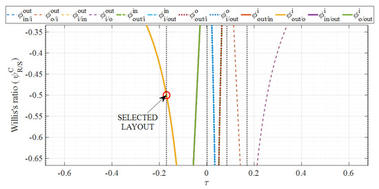
Figure 7.
Design chart for PG synthesis and selected layout with ICE working at 1400 rpm and 2080 Nm.
3.1.4. Corresponding Speed Ratios Selection
As shown in Equations (9)–(12), the MG I speed and torque are ruled by the corresponding speed ratio , while affects the MG O speed and torque. However, for the selected output-split layout, by definition and only can be freely assigned. Since from Equation (10) for , can be selected to let MG O work at the speed resulting in its highest efficiency. Supposing that the best-efficiency operations of MG O are realized at 3500 rpm, it is simply:
At this point, the operations of the electric machines are defined for any system operating point. Table 4 shows MG I and MG O speed and torque for the extreme values of for each drilling process phase.

Table 4.
MG I and MG O extreme operations for each drilling subphase with ICE working at 1400 rpm and 2080 Nm. MG I torque values exceeding the maximum torque of 4775 Nm are bolded.
Table 4 shows that in drilling, casing, trip out, and trip in phases, the maximum MG I torque of 4775 Nm is not fulfilled. Since the torque demand on the PSU i shaft () is ruled by (Equation (11)), which cannot be imposed freely, a fixed-ratio OG outside the PSU must be deployed to decrease the torque requested to MG I. However, the constraint on MG I maximum speed must be satisfied, then:
As a result, the actual MG I speeds and torques are those shown in Table 5 obtained from Equation (16). The maximum speed and torque constraints are always fulfilled.

Table 5.
MG I speeds and torques after the introduction of the OG .
3.1.5. Ordinary Gearing Synthesis
The last design step involves synthesizing the ordinary gear sets inside the PSU. At this point, the nodal and corresponding speed ratios are defined, as well as the PG synchronous ratio . Thus, Equations (13) and (14) can be evaluated involving each PSU main shaft at least once:
Table 6 shows the possible OGs combinations obtained by assuming that at least one OG can be omitted by having a fixed ratio equal to 1. Note that and are in series; thus, they can be merged in a unique OG . The combinations in the first and third rows seem preferable because the fixed ratios are averagely more easily achievable by single-stage gearing.

Table 6.
OGs possible combinations with ICE working at 1400 rpm and 2080 Nm.
Figure 8 summarizes the functional layout of the output-split transmission designed for the first analyzed case where one of the ICE currently deployed on the drilling rig is kept working at 1400 rpm and 2080 Nm.
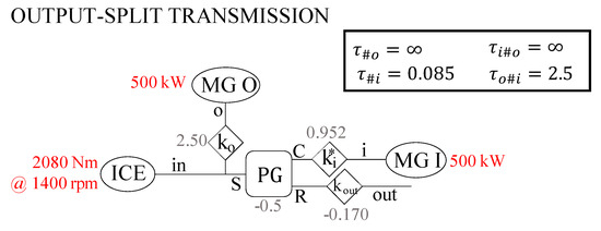
Figure 8.
Functional layout of the output-split transmission designed for ICE working at 1400 rpm and 2080 Nm. The shown OGs arrangement corresponds to the first row of Table 6.
3.2. Second Solution: Downsized ICE
In the previous scenario, Figure 6 shows that, in the majority of drilling rig operating points, the overall power ratio is far lower than one. This means that the ICE power almost always significantly overcomes the output power demand for drill string motion. Consequently, the ICE surplus energy is transferred to the electric unit, and two electric machines with 500 kW of rated power each are required for this purpose. However, a more balanced solution can be found by downsizing the ICE size. For instance, a smaller ICE reaching its most efficient operations at rpm, Nm, and kW would provide an intermediate power that equals the power required for raising the top-drive and hook block, which is the most frequent drilling process subphase since it is performed during drilling, casing, and trip in. In the following, the design process described in Section 2.2 and applied in Section 3.1 is carried out to design the power-split transmission with the above-mentioned downsized ICE.
3.2.1. Identification of the Overall Speed and Power Ratios
The overall speed and power ratios are assessed from Equations (1) and (4), by considering the PSU output speed and output power shown in Figure 2 and Figure 4 and rpm, kW, and Nm. The resulting and for the simulating drilling are shown in Figure 9.

Figure 9.
PSU overall speed and power ratios for the simulated drilling with ICE working at 1400 rpm and 1045 Nm.
3.2.2. Mechanical Points Selection and Electric Machines’ Power Size
The same procedure proposed in Section 3.1.2 is carried out. In this case, the power-split functional layout resulting in the lowest electric machines’ rated power is an input-split solution with and . Thus, the power flowing through MG I is null when the top-drive and hook block alone are raised. Moreover, MG O power is zero for both top-drive and hook block lowering and raising; consequently, when the top-drive and hook block are raised, the electric unit is not involved in the operations, while when they are lowered the powertrain works in a parallel hybrid mode. The maximum power demand for MG I is 307 kW, while for MG O, it is 281 kW. Thus, we select two electric motors with 315 kW rated power: the nearest power size commonly available on the market. This value is significantly lower than the 500-kW rated power required in the first solution. The selected motor-generators have a base speed of 1000 rpm, a maximum speed of 4000 rpm, and a maximum torque of 3008 Nm.
3.2.3. Design Chart and Planetary Gearing Synthesis
The design chart obtained from , , , and is shown in Figure 10. Given the coincidence of with , some curves appear overlapped. The selected PG has a Willis’ ratio equal to −1/3, and it is synchronous during the trip out operations at 0.17. Since the chosen layout belongs to the curve (coincident with ), the PG carrier is connected to the ICE, the ring gear to MG I, and the sun gear to MG O, whose rotational speed is proportional to the PSU output speed.
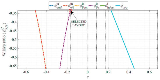
Figure 10.
Design chart for PG synthesis and selected layout with ICE working at 1400 rpm and 1045 Nm.
3.2.4. Corresponding Speed Ratios Selection
For the selected input-split layout, both and can be freely assigned. From Equations (10) and (12), rules the MG O speed and torque; in particular, it is the ratio between and when . Thus, can be evaluated by the following expression to fulfill the MG O maximum speed constraint:
Similarly, rules the MG I speed and torque (Equations (9) and (11)). However, the same approach is not suited for selection, since is not the extreme value of the operating range. Nonetheless, Equation (11) shows that for . As a result, can be selected to let MG I work at the torque resulting in its highest efficiency, namely, at the highest achievable torque that equals the torque provided for the MG I maximum speed:
The resulting MG I and MG O speeds and torques are reported in Table 7.

Table 7.
MG I and MG O extreme operations for each drilling subphase with ICE working at 1400 rpm and 1045 Nm. MG O torque values exceeding the maximum torque of 3008 Nm are bolded.
These results show that the constraint on MG O maximum torque does not allow the full braking energy recovery when the casing is performed at a higher depth (lower ). To overcome the problem, it is not advisable to deploy an ordinary gear outside the PSU to decrease the MG O required torque because this would violate the constraint on MG O maximum speed. However, the MG O torque can be limited in several ways, for instance, by modifying ICE operations under critical casing conditions, introducing dissipative braking to lower and increase the PSU overall power ratio η, or increasing the MG O power size.
3.2.5. Ordinary Gearing Synthesis
Equations (13) and (14) for synthesizing the ordinary gear sets in the described input-split layout result in:
Table 8 shows the possible OGs combinations obtained by assuming that at least one OG can be omitted by having a fixed ratio equal to 1. The combination in the fourth row seems preferable because the fixed ratios are averagely more easily achievable by single-stage gearing.

Table 8.
OGs possible combinations with ICE working at 1400 rpm and 1045 Nm.
Figure 11 summarizes the functional layout of the input-split transmission designed for the second analyzed case where a downsized ICE working at 1400 rpm and 1045 Nm. is deployed.
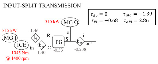
Figure 11.
Functional layout of the input-split transmission designed for ICE working at 1400 rpm and 1045 Nm.
4. Discussion and Conclusions
The parametric model addressed in this paper for power-split transmissions design allows a hierarchical and modular procedure here applied to hybridize an oil drilling rig to recover energy braking during the gravity-driven lowering phases. Moreover, further energy saving is obtained from the thermal unit downsizing and the possibility for the engine to continuously work at its most efficient operation.
Unlike the approaches based on the optimization of mature power-split layouts, the design process adopted here is completely general and can lead to any single-mode shunt or compound power-split transmission with up to two planetary gear sets. Each design phase is decoupled from the others. Hence, once the ICE is selected, the designer can prioritize the sizing of the electric machines, the most expensive equipment, before defining the transmission constructive arrangement. In this respect, a strategy aimed at minimizing the motor-generators’ rated power is pursued. Then, the mechanical devices inside the PSU are synthesized, prioritizing the selection of the PGs. The PGs’ Willis’ ratio, synchronism, and connections can be selected by a design chart describing the power-split unit kinematics to avoid constructive complexity and improve mechanical efficiency. Lastly, the OGs necessary to meet the kinematics requirements are synthesized. It is worth noting that the designer has complete control over the viable choices in each design stage, unlike in a computer-aided design process relying on automated algorithms based on topological models, such as the graph theory.
Although a realistic but simplified working cycle is simulated for the drilling rig operations—for instance, any dynamic aspect is neglected, likewise any interaction between the drill string or the casing with the wellbore walls—the design procedure validity is not compromised. Indeed, it would be sufficient to retrieve data from a real similar drilling rig to identify the actual overall speed and power ratios on which the design process should be based.
The main aim of this paper was to apply the addressed modular and parametric design procedure to the novel case study of the oil drilling rig. Although an energy management strategy is essential to select the ICE power size properly, two scenarios differing in engine power size are investigated to probe how the engine selection affects the electric machines’ power size. In the first one, only one of the two engines deployed in the original drilling rig plant is kept in the hybrid layout. We supposed that the engine always operates at its most efficient point, providing 305 kW. An output-split transmission results in the lowest electric machines’ power size, equal to 500 kW each. However, the power required in the transmission output for hoisting operations is widely lower than 305 kW for most drilling rig functioning. This implies that such a high engine power is almost always unnecessary and causes an oversizing of the electric unit, which has to store the energy recovered during the lowering phases and the ICE surplus power. Therefore, a second scenario with a downsized engine is considered. In this case, the ICE provides 153 kW, and two electric machines with 315 kW of rated power each are required. The transmission synthesis results in an input-split layout. The second scenario seems preferable given the smaller electric unit resulting in lower costs, proving that the initial ICE sizing is crucial to optimize the hybridized powertrain in both energetical and cost-effective terms. Therefore, further research will focus on minimizing the overall energy consumption as well as the thermal and electric unit power size by introducing proper engine control strategies. For instance, in both scenarios, the engine is kept on during regenerative braking, which would not be necessary for the only drawworks operations. Including a proper on-off control strategy for the engine would further reduce the power unit size. Nonetheless, the proposed solutions enable significant fuel saving compared to the current non-hybrid plant, thanks to thermal unit downsizing and the possibility of exploiting the braking energy recovered and stored in the battery to supply other auxiliary loads of the drilling rig plant.
Last but not least, future developments of this work should include the extension of the described design process to multimode transmissions with any number of PGs.
Author Contributions
Conceptualization, M.C., A.C. and D.L.; methodology, M.C. and A.C.; software, D.L. and A.C.; investigation, A.C.; data curation, D.L.; writing—original draft preparation, A.C.; writing—review and editing, M.C., A.C. and D.L.; supervision, M.C. All authors have read and agreed to the published version of the manuscript.
Funding
This research received no external funding.
Institutional Review Board Statement
Not applicable.
Informed Consent Statement
Not applicable.
Data Availability Statement
Not applicable.
Conflicts of Interest
The authors declare no conflict of interest.
References
- Krithika, V.; Subramani, C. A Comprehensive Review on Choice of Hybrid Vehicles and Power Converters, Control Strategies for Hybrid Electric Vehicles. Int. J. Energy Res. 2018, 42, 1789–1812. [Google Scholar] [CrossRef]
- Tran, D.D.; Vafaeipour, M.; El Baghdadi, M.; Barrero, R.; Van Mierlo, J.; Hegazy, O. Thorough State-of-the-Art Analysis of Electric and Hybrid Vehicle Powertrains: Topologies and Integrated Energy Management Strategies. Renew. Sustain. Energy Rev. 2020, 119, 109596. [Google Scholar] [CrossRef]
- Zhuang, W.; Li (Eben), S.; Zhang, X.; Kum, D.; Song, Z.; Yin, G.; Ju, F. A Survey of Powertrain Configuration Studies on Hybrid Electric Vehicles. Appl. Energy 2020, 262, 114553. [Google Scholar] [CrossRef]
- Capata, R. Preliminary Analysis of a New Power Train Concept for a City Hybrid Vehicle. Designs 2021, 5, 19. [Google Scholar] [CrossRef]
- Karimi, D.; Behi, H.; Van Mierlo, J.; Berecibar, M. Advanced Thermal Management Systems for High-Power Lithium-Ion Capacitors: A Comprehensive Review. Designs 2022, 6, 53. [Google Scholar] [CrossRef]
- Wang, L.; Cui, Y.; Zhang, F.; Li, G. Architectures of Planetary Hybrid Powertrain System: Review, Classification and Comparison. Energies 2020, 13, 329. [Google Scholar] [CrossRef]
- İnce, E.; Güler, M.A. On the Advantages of the New Power-Split Infinitely Variable Transmission over Conventional Mechanical Transmissions Based on Fuel Consumption Analysis. J. Clean. Prod. 2020, 244, 118795. [Google Scholar] [CrossRef]
- Zeng, X.; Wang, J. Analysis and Design of the Power-Split Device for Hybrid Systems; Springer: Singapore, 2017; ISBN 9789811042720. [Google Scholar]
- Zhao, Z.; Tang, P.; Li, H. Generation, Screening, and Optimization of Powertrain Configurations for Power-Split Hybrid Electric Vehicle: A Comprehensive Overview. IEEE Trans. Transp. Electrif. 2022, 8, 325–344. [Google Scholar] [CrossRef]
- Buchsbaum, F.; Freudenstein, F. Synthesis of Kinematic Structure of Geared Kinematic Chains and Other Mechanisms. J. Mech. 1970, 5, 357–392. [Google Scholar] [CrossRef]
- Gomà Ayats, J.R.; Diego-Ayala, U.; Minguella Canela, J.; Fenollosa, F.; Vivancos, J. Hypergraphs for the Analysis of Complex Mechanisms Comprising Planetary Gear Trains and Other Variable or Fixed Transmissions. Mech. Mach. Theory 2012, 51, 217–229. [Google Scholar] [CrossRef]
- Pei, H.; Hu, X.; Yang, Y.; Tang, X.; Hou, C.; Cao, D. Configuration Optimization for Improving Fuel Efficiency of Power Split Hybrid Powertrains with a Single Planetary Gear. Appl. Energy 2018, 214, 103–116. [Google Scholar] [CrossRef]
- Pei, H.; Hu, X.; Yang, Y.; Peng, H.; Hu, L.; Lin, X. Designing Multi-Mode Power Split Hybrid Electric Vehicles Using the Hierarchical Topological Graph Theory. IEEE Trans. Veh. Technol. 2020, 69, 7159–7171. [Google Scholar] [CrossRef]
- Shanmukhasundaram, V.R.; Rao, Y.V.D.; Regalla, S.P. Enumeration of Displacement Graphs of Epicyclic Gear Train from a given Rotation Graph Using Concept of Building of Kinematic Units. Mech. Mach. Theory 2019, 134, 393–424. [Google Scholar] [CrossRef]
- Du, M.; Yang, L. A Basis for the Computer-Aided Design of the Topological Structure of Planetary Gear Trains. Mech. Mach. Theory 2020, 145, 103690. [Google Scholar] [CrossRef]
- Zhou, X.; Qin, D.; Rotella, D.; Cammalleri, M. Hybrid Electric Vehicle Powertrain Design: Construction of Topologies and Initial Design Schemes. In Advances in Italian Mechanism Science; Springer International Publishing: Cham, Switzerland, 2019; Volume 68, pp. 49–60. [Google Scholar]
- Ngo, H.T.; Yan, H. Sen Configuration Synthesis of Parallel Hybrid Transmissions. Mech. Mach. Theory 2016, 97, 51–71. [Google Scholar] [CrossRef]
- Zhang, X.; Li, C.T.; Kum, D.; Peng, H. Prius + and Volt -: Configuration Analysis of Power-Split Hybrid Vehicles with a Single Planetary Gear. IEEE Trans. Veh. Technol. 2012, 61, 3544–3552. [Google Scholar] [CrossRef]
- Wang, W.; Song, R.; Guo, M.; Liu, S. Analysis on Compound-Split Configuration of Power-Split Hybrid Electric Vehicle. Mech. Mach. Theory 2014, 78, 272–288. [Google Scholar] [CrossRef]
- Ke, T.; Ding, H.; Gong, C.; Geng, M. Configuration Synthesis of Nine-Speed Automatic Transmissions Based on Structural Decomposition. Mech. Mach. Theory 2021, 164, 104421. [Google Scholar] [CrossRef]
- Chen, H.; Li, L.; Lange, A.; Küçükay, F. Innovative Dedicated Hybrid Transmission Concepts in the Next Generation of Hybrid Powertrains. SAE Int. J. Altern. Powertrains 2019, 8, 75–88. [Google Scholar] [CrossRef]
- Cammalleri, M.; Rotella, D. Functional Design of Power-Split CVTs: An Uncoupled Hierarchical Optimized Model. Mech. Mach. Theory 2017, 116, 294–309. [Google Scholar] [CrossRef]
- Rotella, D.; Cammalleri, M.; Qin, D.; Zhou, X. A Simple Method for the Design of Hybrid Electric Power-Split Cvts: A Case Study. In Advances in Italian Mechanism Science; Springer International Publishing: Cham, Switzerland, 2019; Volume 68, pp. 70–79. [Google Scholar]
- Cammalleri, M.; Castellano, A. Analysis of Hybrid Vehicle Transmissions with Any Number of Modes and Planetary Gearing: Kinematics, Power Flows, Mechanical Power Losses. Mech. Mach. Theory 2021, 162, 104350. [Google Scholar] [CrossRef]
- Rotella, D.; Cammalleri, M. Power Losses in Power-Split CVTs: A Fast Black-Box Approximate Method. Mech. Mach. Theory 2018, 128, 528–543. [Google Scholar] [CrossRef]
- Castellano, A.; Cammalleri, M. Global Efficiency of Power-Split Hybrid Electric Powertrain. In Mechanisms and Machine Science, Proceedings of the I4SDG Workshop 2021, I4SDG 2021, Online, 25–26 November 2021; Quaglia, G., Gasparetto, A., Petuya, V., Carbone, G., Eds.; Springer: Cham, Switzerland, 2022; Volume 108, pp. 502–511. ISBN 9783030873820. [Google Scholar]
- Castellano, A.; Cammalleri, M. Optimal Operation of Power-Split Hybrid Electric Powertrain: Comparison between Two Performance Indices. Int. J. Mech. Control 2022, 23, 3–14. [Google Scholar]
- Castellano, A.; Cammalleri, M. Power Losses Minimization for Optimal Operating Maps in Power-Split Hevs: A Case Study on the Chevrolet Volt. Appl. Sci. 2021, 11, 7779. [Google Scholar] [CrossRef]
- Lyons, W.C.; Plisga, G.J.; Lorenz, M.D.B.T. Standard Handbook of Petroleum and Natural Gas Engineering; Gulf Professional Publishing: Houston, TX, USA, 2016; ISBN 9780123838469. [Google Scholar]
- Ismail, A.; Moustafa, W. New Hybrid Drill Bit with Innovative Technology Improves Drilling Efficiency in Challenging Jordanian Drilling Project. Soc. Pet. Eng. SPE Saudi Arab. Sect. Tech. Symp. Exhib. 2014. [Google Scholar] [CrossRef]
- Yadav, P.; Kumar, R.; Panda, S.K.; Chang, C.S. An Improved Harmony Search Algorithm for Optimal Scheduling of the Diesel Generators in Oil Rig Platforms. Energy Convers. Manag. 2011, 52, 893–902. [Google Scholar] [CrossRef]
- Pavković, D.; Sedić, A.; Guzović, Z. Oil Drilling Rig Diesel Power-Plant Fuel Efficiency Improvement Potentials through Rule-Based Generator Scheduling and Utilization of Battery Energy Storage System. Energy Convers. Manag. 2016, 121, 194–211. [Google Scholar] [CrossRef]
- Chupin, E.; Frolov, K.; Korzhavin, M.; Zhdaneev, O. Energy Storage Systems for Drilling Rigs. J. Pet. Explor. Prod. Technol. 2022, 12, 341–350. [Google Scholar] [CrossRef]
- Bilgin, M.; Donen, J.; Scaini, V.; Snijder, M. World’s First Hybrid Drilling Rig. In Proceedings of the SPE/IADC Drilling Conference and Exhibition, Galveston, TX, USA, 3–5 March 2020. [Google Scholar] [CrossRef]
- Lujun, Z. An Energy-Saving Oil Drilling Rig for Recovering Potential Energy and Decreasing Motor Power. Energy Convers. Manag. 2011, 52, 359–365. [Google Scholar] [CrossRef]
- Dai, X.; Wei, K.; Zhang, X. Analysis of the Peak Load Leveling Mode of a Hybrid Power System with Flywheel Energy Storage in Oil Drilling Rig. Energies 2019, 12, 606. [Google Scholar] [CrossRef] [Green Version]
- Lupașcu (Oprea), A.-M.; Ionescu, V.-M.; Potârniche, I.; Năvrăpescu, V.; Săpunaru, A.-A. Increase of Energy Efficiency of Electrically Driven Drilling Installations by Valorising the Braking Regime of the Draw Works upon Descending the Pipe Line. EMERG Energy. Environ. Effic. Resour. Glob. 2020, 6, 33–40. [Google Scholar] [CrossRef]
- Hamada, A.T.; Orhan, M.F. An Overview of Regenerative Braking Systems. J. Energy Storage 2022, 52, 105033. [Google Scholar] [CrossRef]
- Drillmec Mobile Rigs. Available online: https://www.drillmec.com/en/onshore/mobile-rigs (accessed on 14 May 2022).
- Rotella, D.; Cammalleri, M. Direct Analysis of Power-Split CVTs: A Unified Method. Mech. Mach. Theory 2018, 121, 116–127. [Google Scholar] [CrossRef]
Publisher’s Note: MDPI stays neutral with regard to jurisdictional claims in published maps and institutional affiliations. |
© 2022 by the authors. Licensee MDPI, Basel, Switzerland. This article is an open access article distributed under the terms and conditions of the Creative Commons Attribution (CC BY) license (https://creativecommons.org/licenses/by/4.0/).