
Development of a Dynamic Hands-Free Door Opener to Prevent COVID-19 Pandemic Spreading

 ,
,  , ,
, , 
Abstract
:1. Introduction
1.1. Handles in the Spread of Viruses and Bacteria
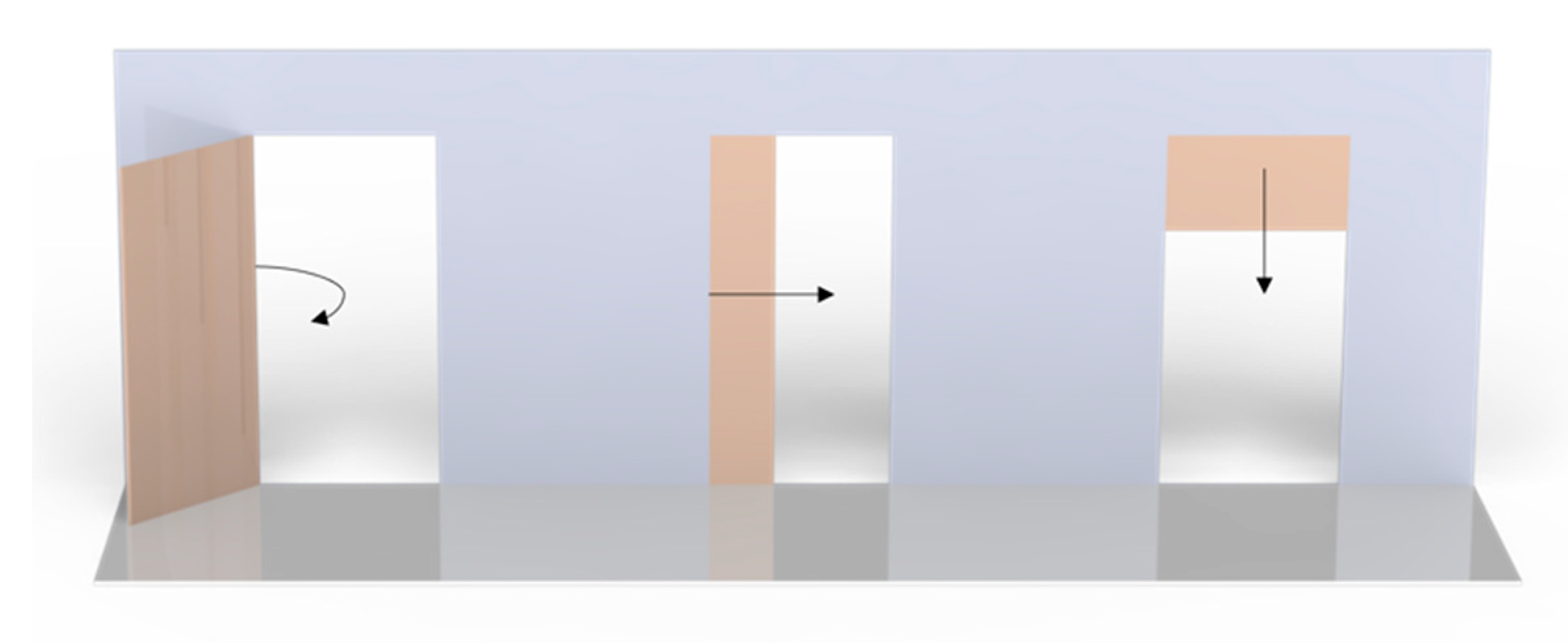
1.2. Door Opening Systems
1.3. Auxiliary Devices for Door Opening Systems
1.4. Proposed Dynamic Hands-Free Door Opener
2. Materials and Methods
2.1. Ergonomics, Interaction Concepts and Design
- “Affordance” is probably the principle that could have the most significant impact on this project and can be defined as the relationship between a physical object and a person (or any agent: animal, human, or even machine and robot). The quality of an object allows the user to identify its functionality without previous explanation, which can happen intuitively (e.g., doorknob) or based on previous experiences (e.g., white colour can mean peace). The greater the “affordance”, the better the identification of its use. It is important to note that “affordances” of physical objects are based on their size, format, and weight, while those of virtual object (web, app, etc.) happen through graphic representations and metaphors;
- “Signifiers” refer to any mark, sound, or any perceptible indicator that communicates the appropriate behavior to a person. These signs can be deliberate and intentional, but also accidental and unintentional;
- “Constraints” are powerful clues limiting the set of possible actions, which can be of physical, cultural, semantic, and logical order. The deliberate use of design restrictions allows people to readily determine the appropriate course of action, even in a new situation;
- “Feedback” concerns the communication of the results of an action and contributes decisively to reducing the user’s frustration and stress.
- Creating a system appropriate for various handle geometries, ensuring its versatility;
- Manufacturing using an easy-to-clean material and geometry, enabling its decontamination;
- Guaranteeing fundamental characteristics/properties for intensive use, considering mechanical resistance, stiffness, and resistance to fatigue;
- Designing for intuitive use.
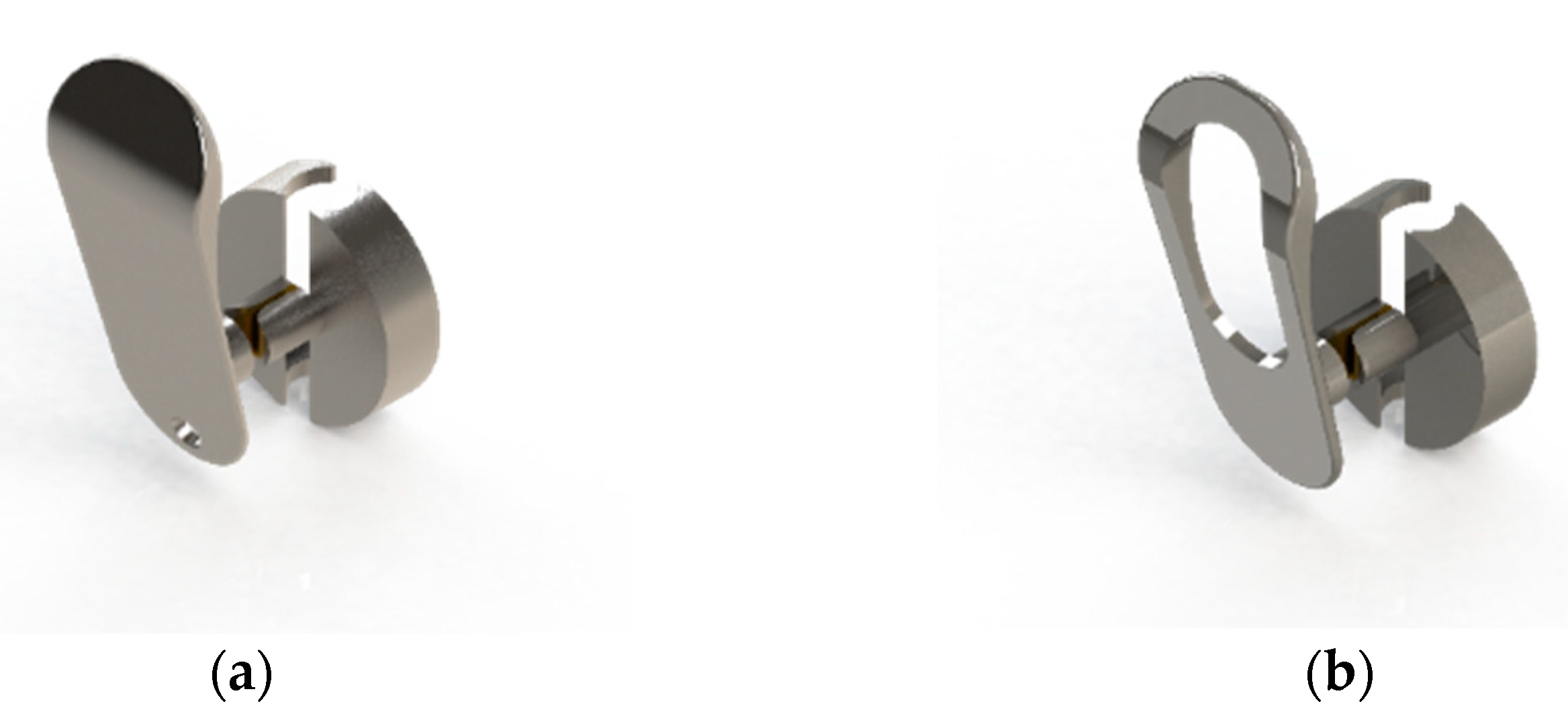
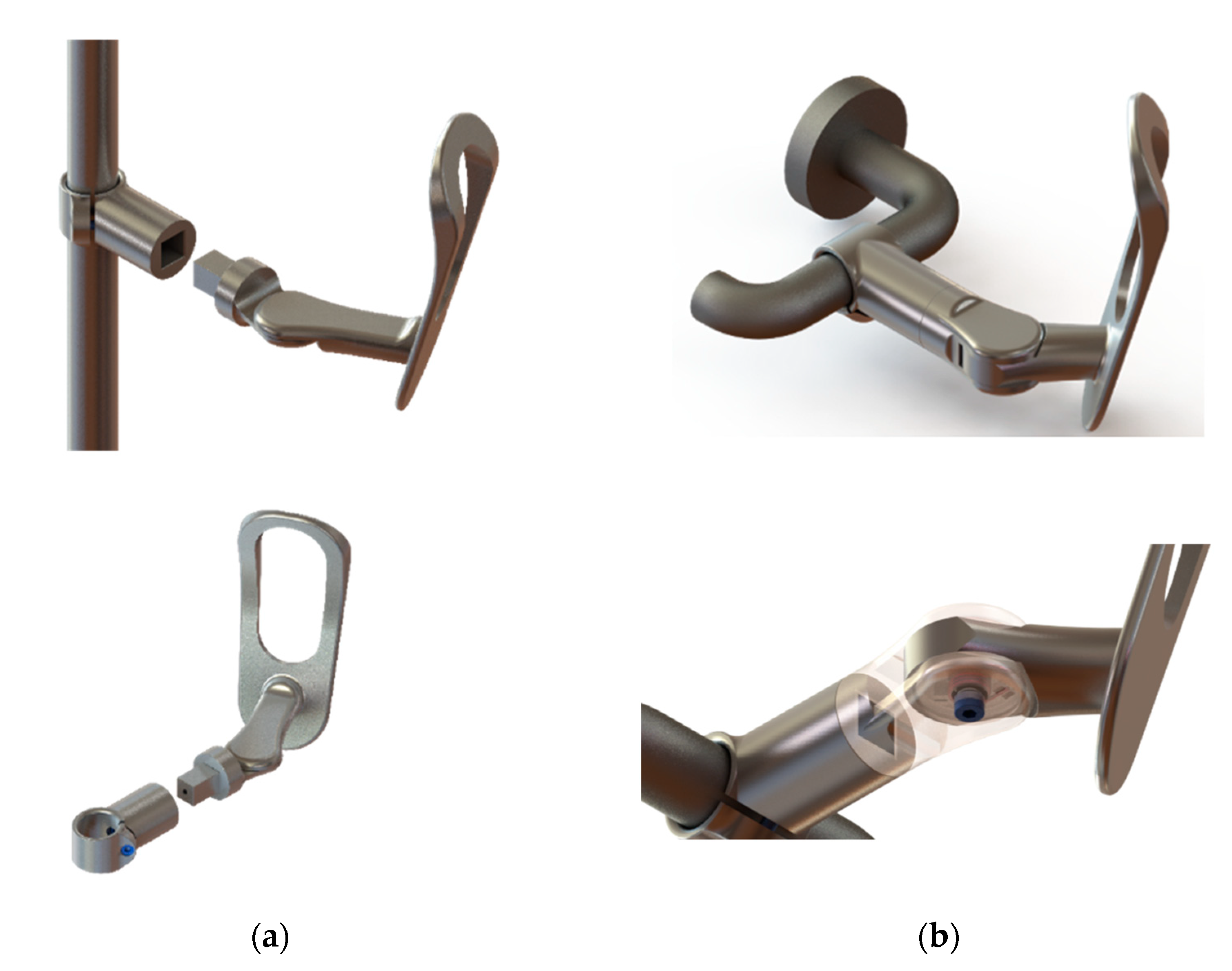
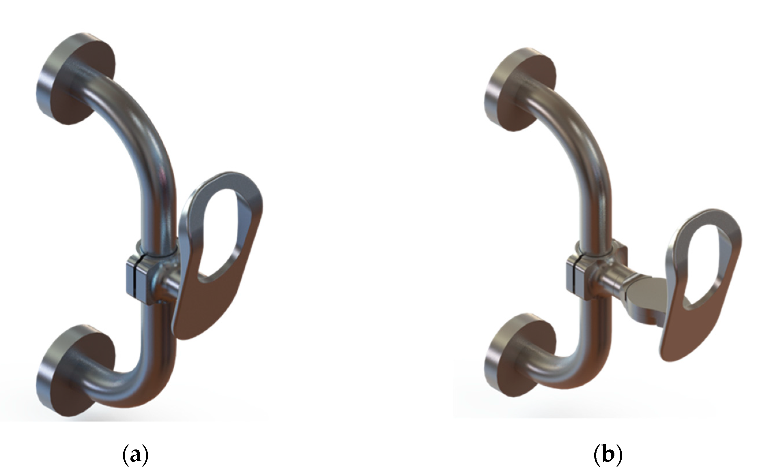
2.2. Geometrical Models—Description of the Project Evolution
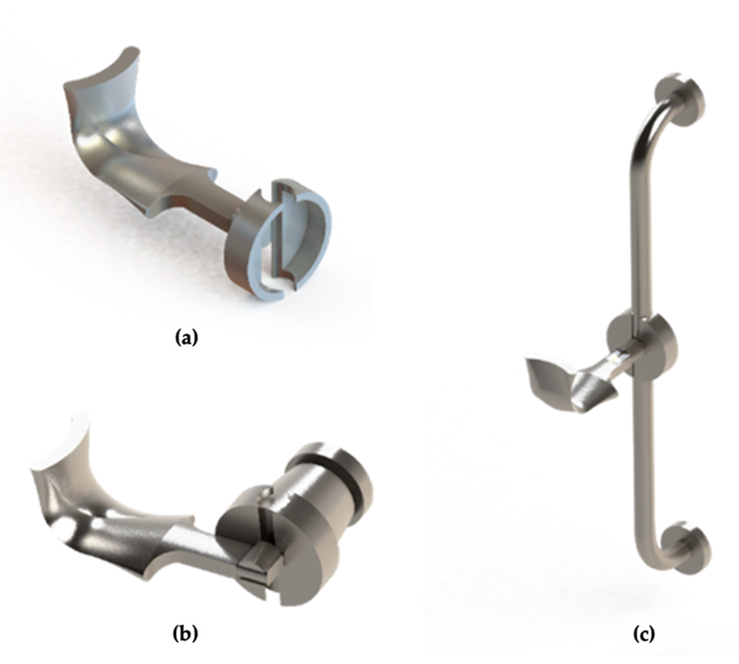
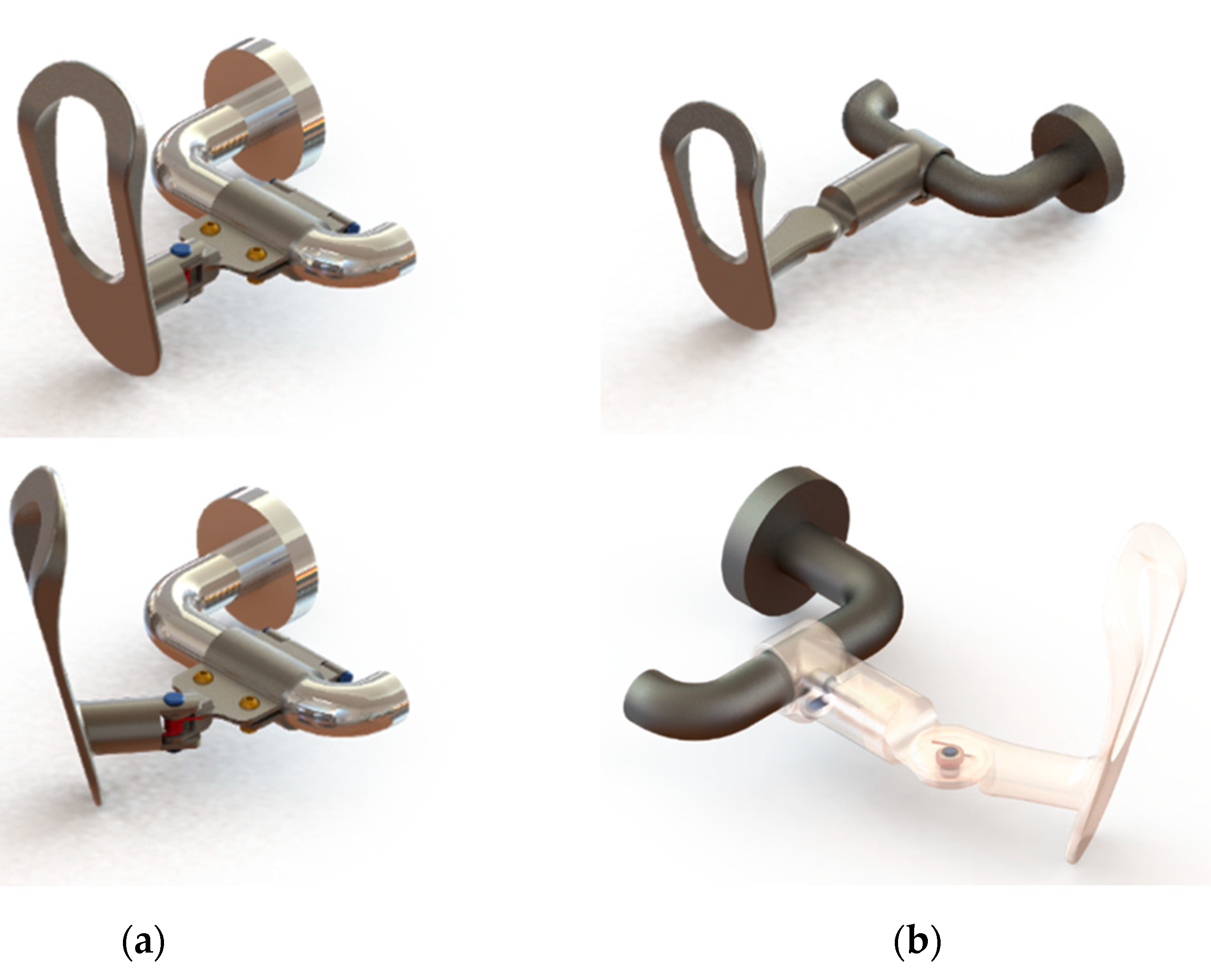
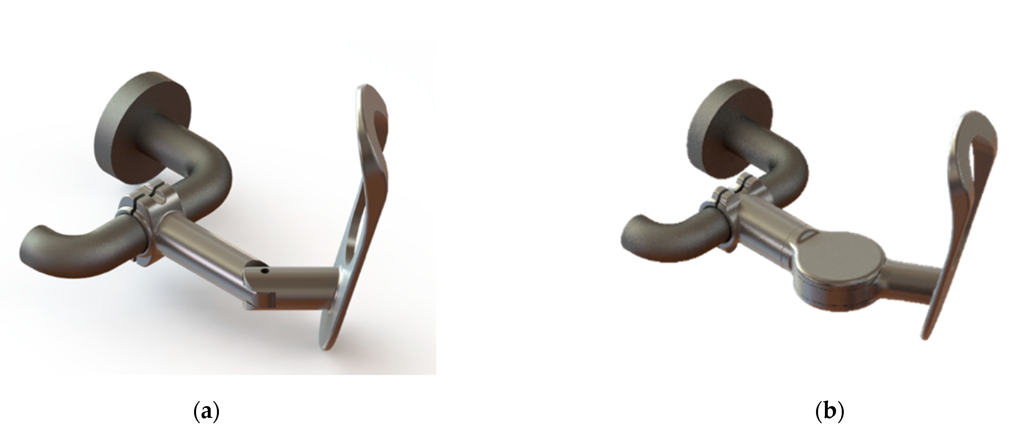
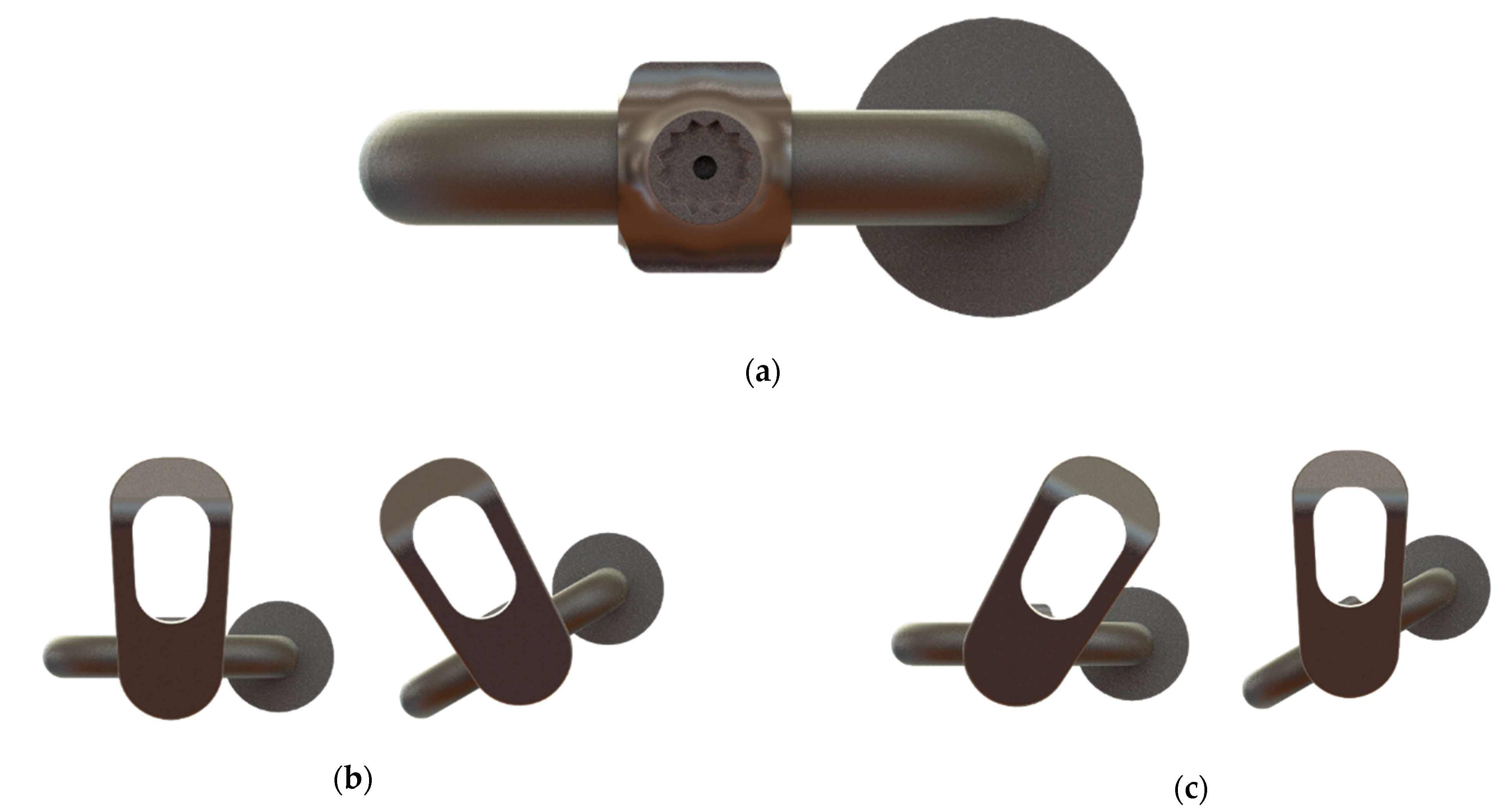
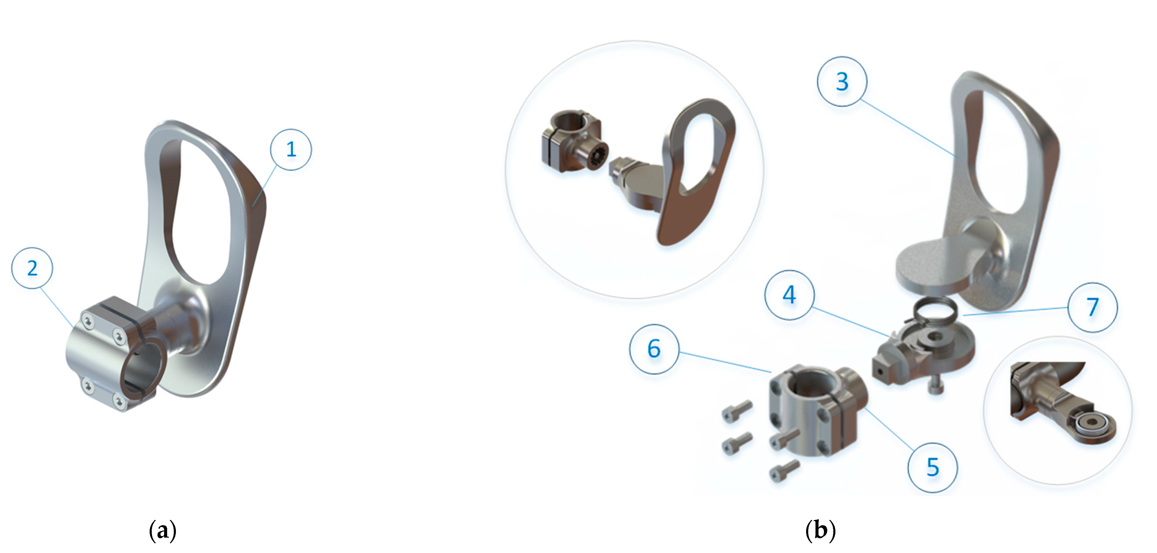
2.3. Final Models
2.4. Material
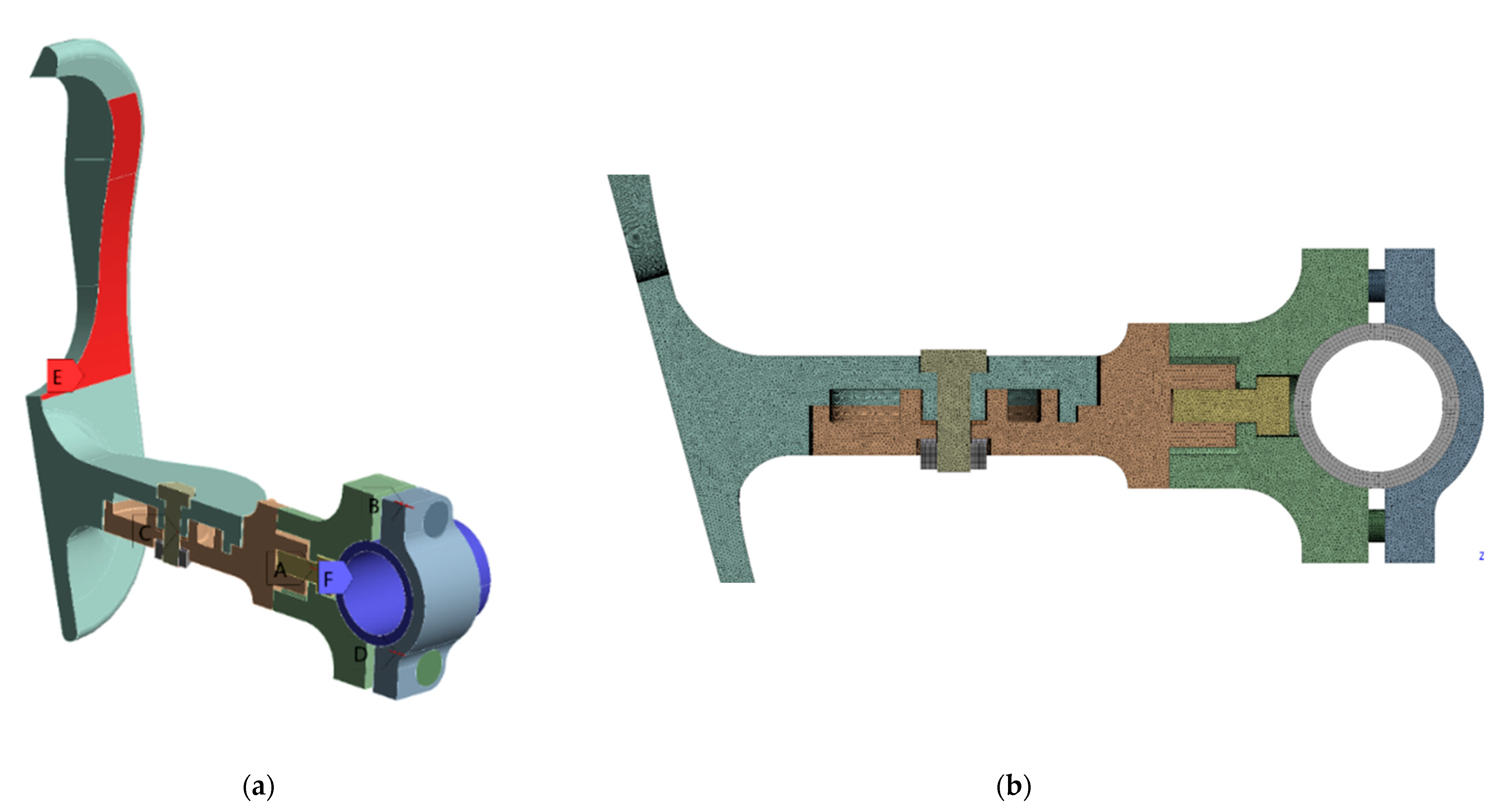
2.5. Numerical Models
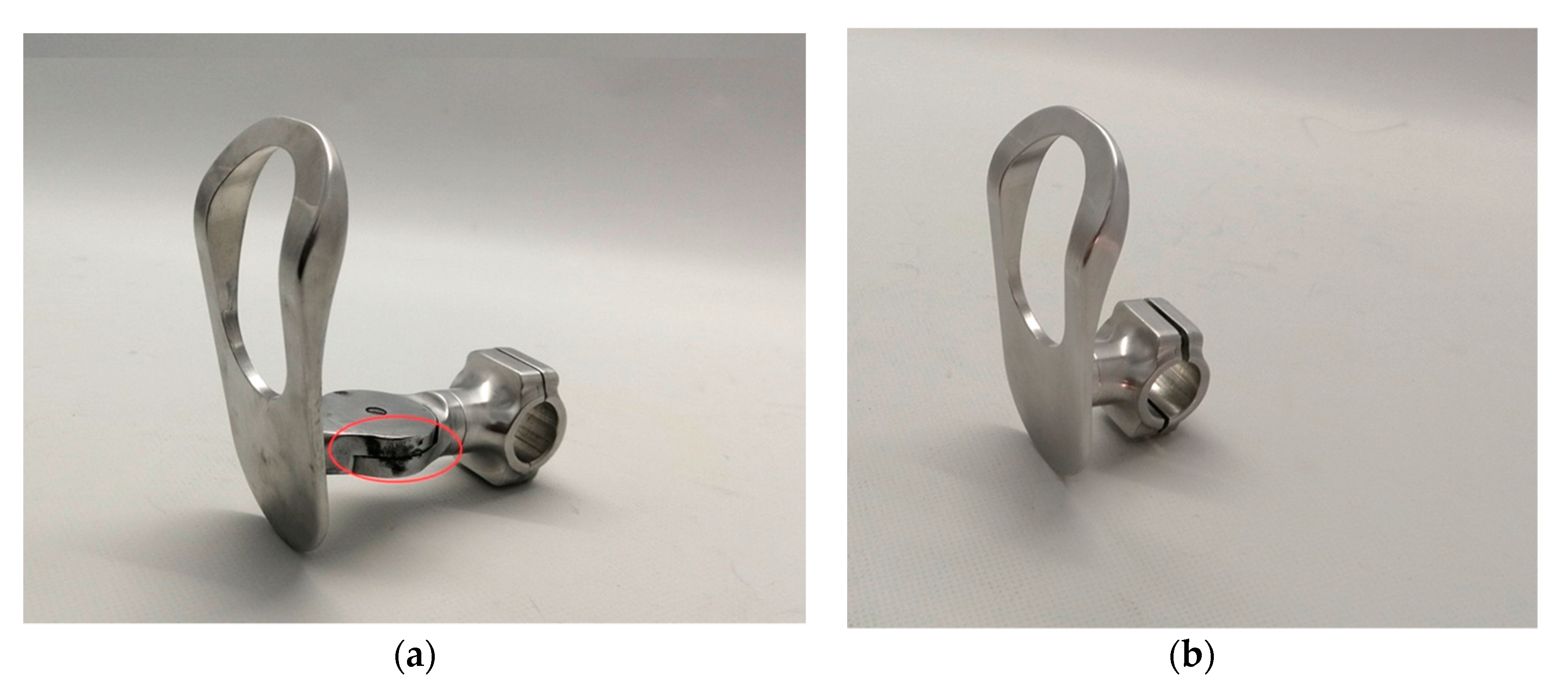
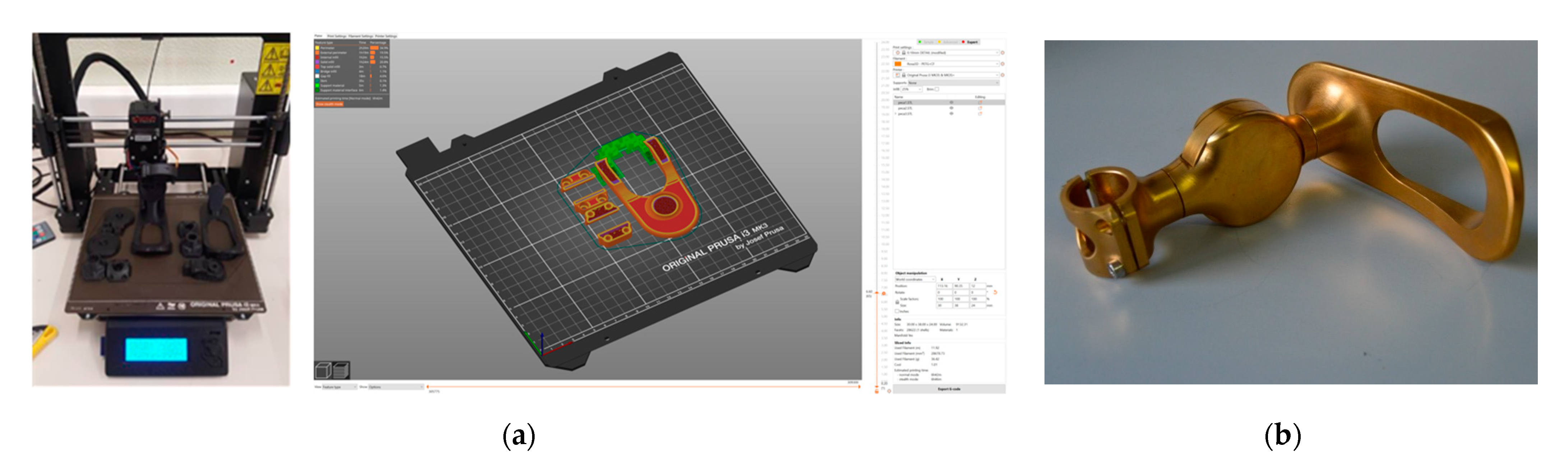
2.6. Manufacturing
2.7. Usability Testing Protocol
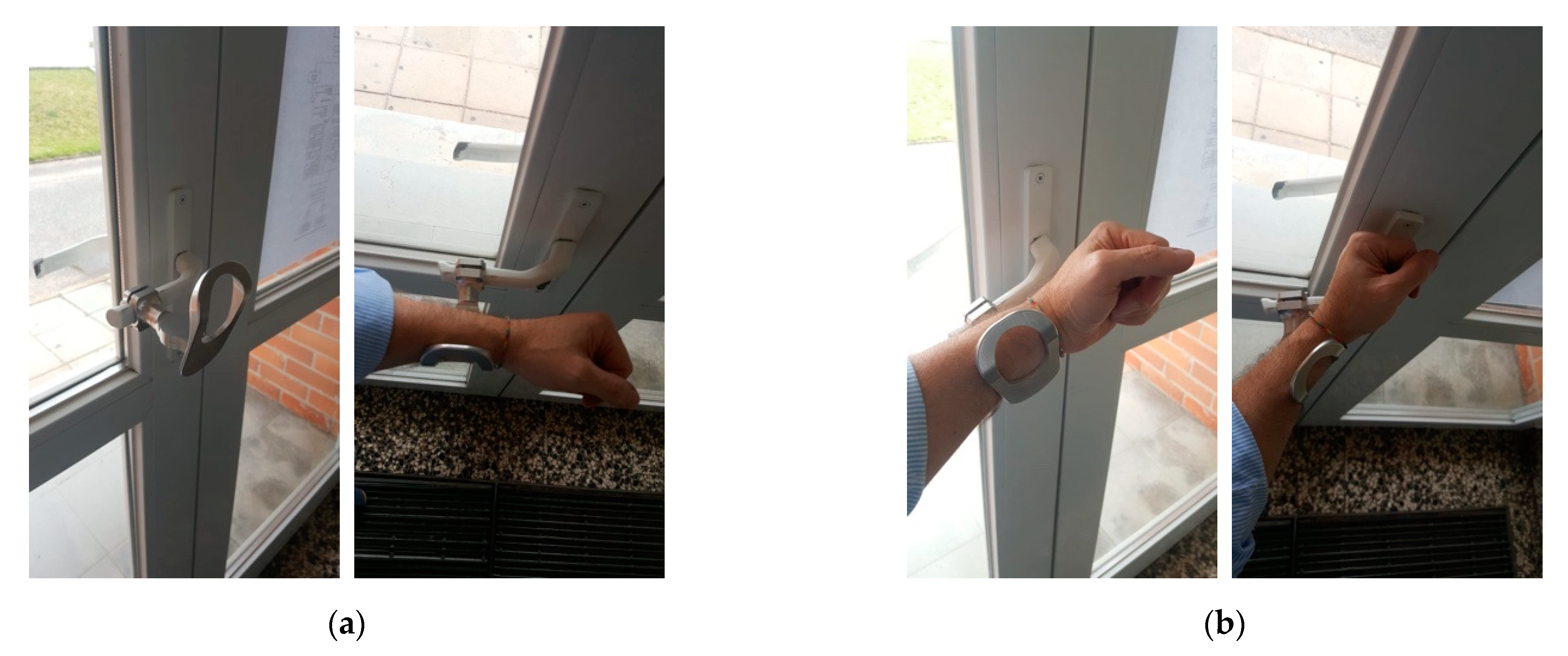
- Short-fixed, referred to as “A”. The simplest device, without dynamic rotation and with a short distance to the handle;
- Long-fixed, referred to as “B”. The same as dynamic, but with dynamic rotation blocked;
- Dynamic, referred to as “C”. The developed device, with dynamic rotation to follow the arm.
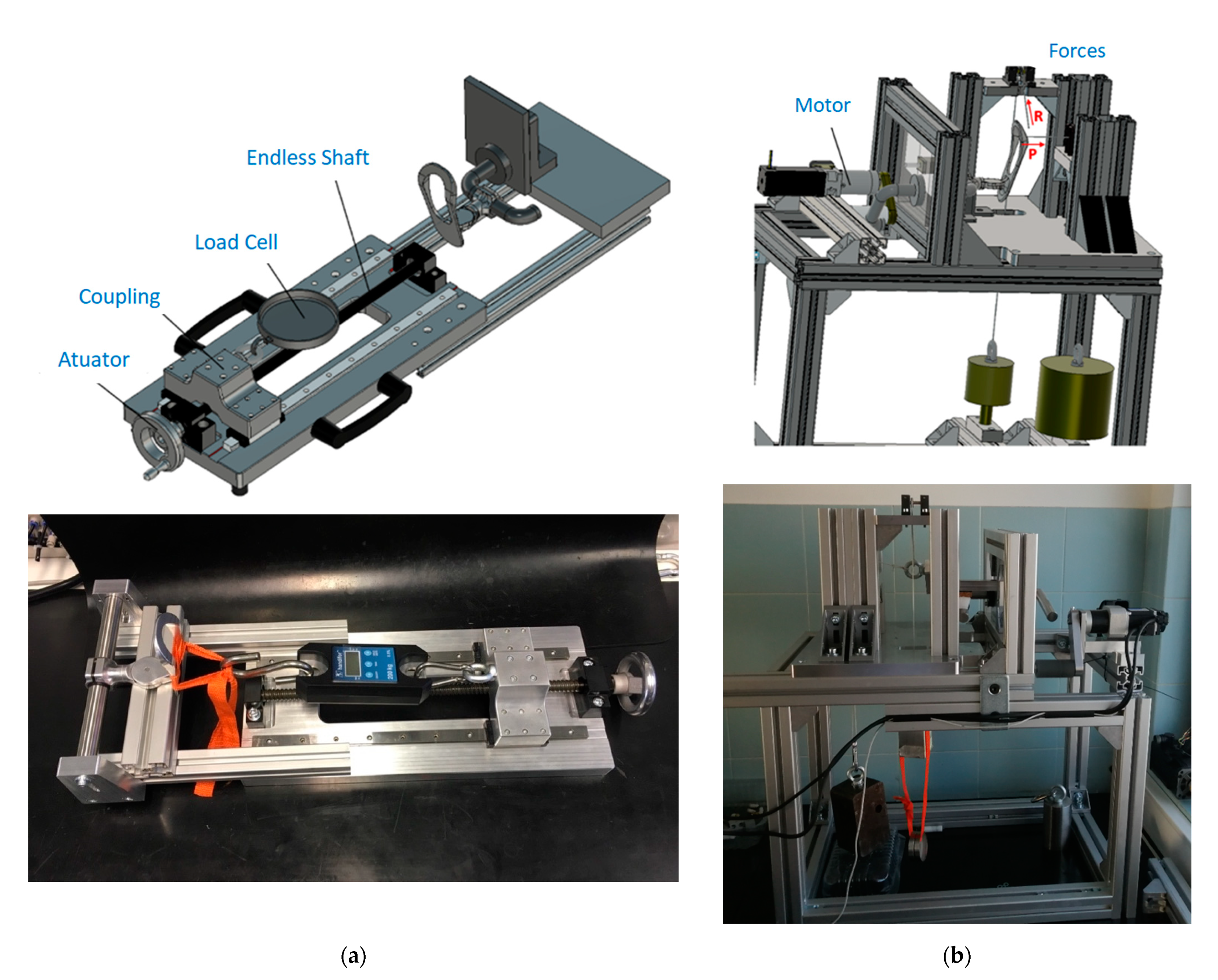
2.8. Experimental Tests
3. Results
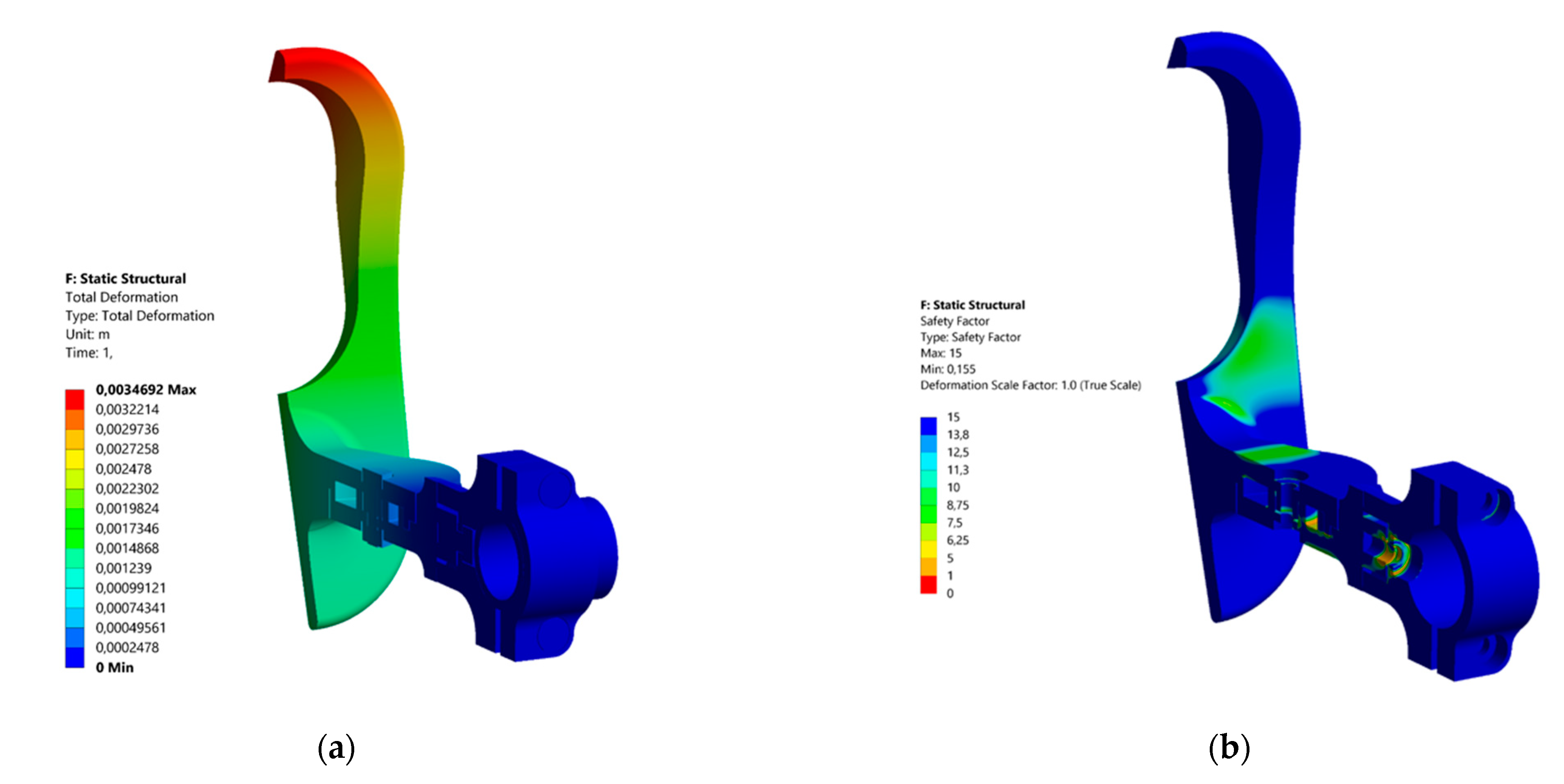
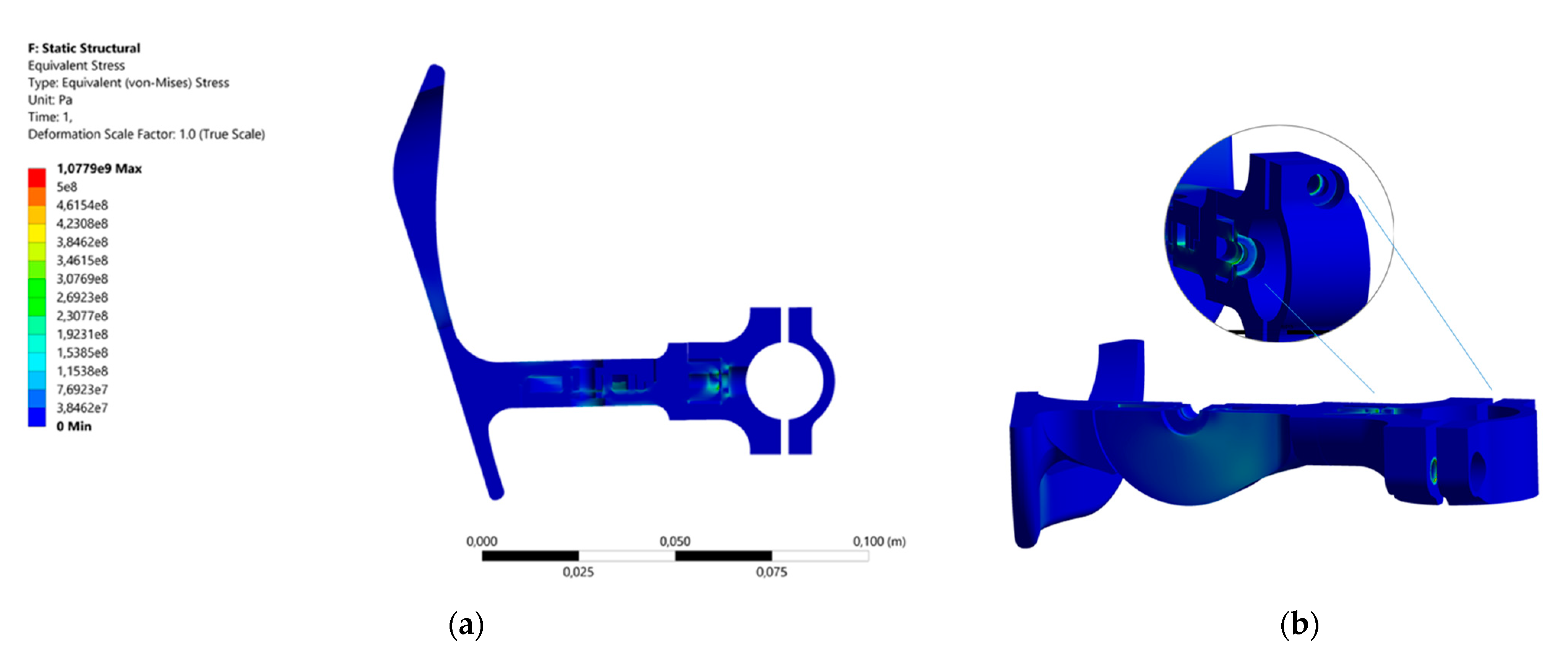
3.1. Numerical Results
3.2. Usability Results
3.2.1. Participants
3.2.2. Habits/Easiness of Door Opening
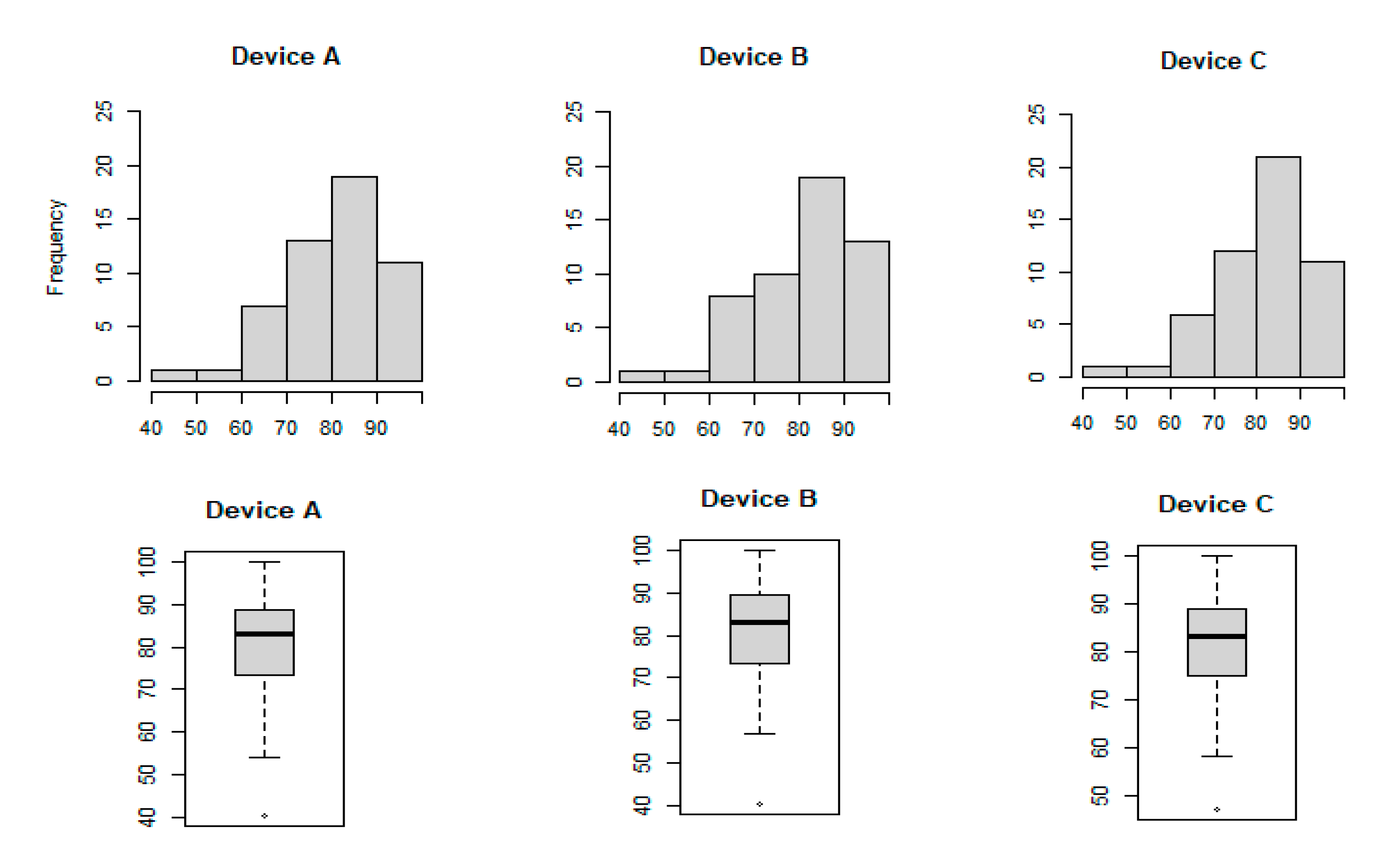
3.3. Statistical Results
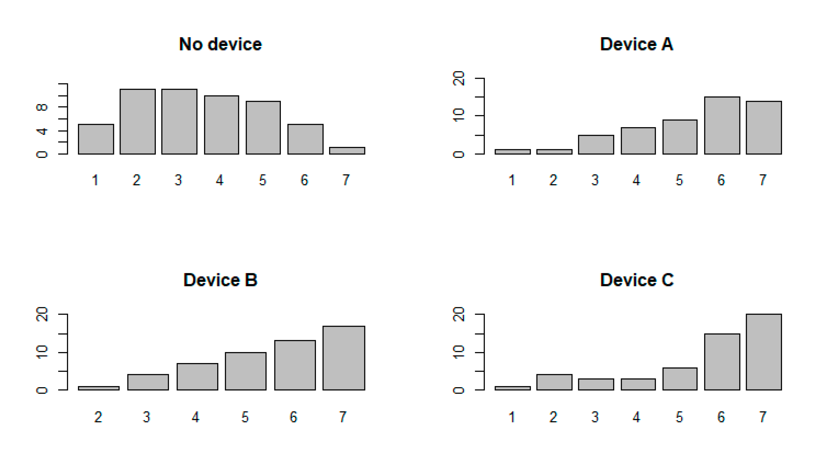
3.4. Experimental Results
4. Discussion
5. Conclusions
Author Contributions
Funding
Institutional Review Board Statement
Informed Consent Statement
Data Availability Statement
Acknowledgments
Conflicts of Interest
References
- Woodson, W.E.; Tilmann, B.; Tilmann, P. Human Factors Design Handbook, 2nd ed.; McGraw-Hill Education: New York, NY, USA, 1992. [Google Scholar]
- Wojgani, H.; Kehsa, C.; Cloutman-Green, E.; Gray, C.; Gant, V.; Klein, N. Hospital door handle design and their contamination with bacteria: A real life observational study. Are we pulling against closed doors? PLoS ONE 2012, 7, e40171. [Google Scholar] [CrossRef] [PubMed]
- Odigie, A.; Ekhiase, F.; Orjiakor, P.; Omozuwa, S. The role of door handles in the spread of microorganisms of public health consequences in University of Benin Teaching Hospital (UBTH), Benin City, Edo State. Pharm. Sci. Technol. 2017, 1, 20–26. [Google Scholar] [CrossRef]
- Carvalho, C. Acessibilidade e Design Universal de Portas—Requisitos Dimensionais e Funcionais de Utilizadores com Incapacidades Motoras e de Cães de Serviço. Master’s Thesis, University of Porto, Porto, Portugal, 2012. Available online: https://repositorio-aberto.up.pt/bitstream/10216/65192/2/26375.pdf (accessed on 5 April 2021).
- Sanitgrasp. Available online: http://www.sanitgrasp.com/product-ada-compliance.html (accessed on 22 April 2021).
- Toepener. Available online: https://www.thetoepener.com/walk (accessed on 22 April 2021).
- Sanitary Door Opener. Available online: https://sanitarydooropener.com/ (accessed on 10 April 2021).
- François, P.M.; Bonnet, X.; Kosior, J.; Adam, J.; Khonsari, R.H. 3D-printed contact-free devices designed and dispatched against the COVID-19 pandemic: The 3D COVID initiative. J. Stomatol. Oral Maxillofac. Surgery 2020, 20. [Google Scholar] [CrossRef] [PubMed]
- Intulon. Available online: https://www.intulon.com/index.php?route=product/product&product_id=69 (accessed on 10 April 2021).
- Materialize. Available online: https://www.materialise.com/en/hands-free-door-opener (accessed on 12 April 2021).
- Shaftmodule. Available online: http://shaftmodule.pt/#rec190651665 (accessed on 12 April 2021).
- Adapta. Available online: https://www.adapta.io/ (accessed on 12 April 2021).
- Planet NoHandler. Available online: https://www.assaabloyopeningsolutions.pl/en/planet-nohander/ (accessed on 12 April 2021).
- StepNpull. Available online: https://www.stepnpull.co.uk/ (accessed on 12 April 2021).
- HandsFreeDoorPull. Available online: https://handsfreedoorpull.com/ (accessed on 12 April 2021).
- Metiba. Available online: http://www.metiba.com/ (accessed on 12 April 2021).
- Salvendy, G. Handbook of Human Factors as Ergonomics; John Wiley & Sons, Inc.: New Jersey, NJ, USA, 2006. [Google Scholar]
- Norman, D. The Design of Everyday Things; Basic Books: New York, NY, USA, 2013. [Google Scholar]
- Norman, D. Emotional Design: Why We Love (or Hate) Everyday Things; Basic Books: New York, NY, USA, 2004. [Google Scholar]
- ADA Standards Guide. Available online: https://www.ada.gov/regs2010/2010ADAStandards/2010ADAstandards.htm (accessed on 22 April 2021).
- Null, R. Commentary on universal design. Hous. Soc. 2003, 30, 109–118. [Google Scholar] [CrossRef]
- Nielsen, J. Usability Engineering; Morgan Kaufmann Publishers Inc.: San Francisco, CA, USA, 1994. [Google Scholar]
- Brooke, J. SUS: A “quick and dirty” usability scale. In Usability Evaluation in Industry; Jordan, P.W., Thomas, B., Weerdmeester, A., McClelland, I.I., Eds.; Taylor and Francis: London, UK, 1996; pp. 189–194. [Google Scholar]
- Leong, I.K. Aluminium 7075-T6 Cyclic Fatigue Testing at Elevated Temperatures. Master’s Thesis, University of New South Wales, Sydney, Australia, 2008. [Google Scholar]


| Model | Procedures and Implementation |
|---|---|
| ADOD-V1 | The first approach to adapt to different geometries. Identification of improvements to be implemented in the leaf. Relevance to the implementation of the dynamism. |
| ADOD-V2 | Development of a leaf with ergonomic language. Identification of improvements in the clamp system and dimensions. Definition of the L and D shapes as a priority to match the system. |
| ADOD-V3 | The first approach to a dynamic component. Inclusion of a planar spring. Identification of the improvements in the leaf’s dimensions, the clamp system and the type of spring. |
| ADOD-V4 | Implementation of a simple torsional spring. Addition of a simple clamp, allowing four positions of the leaf. |
| ADOD-V5 | Addition of a second torsional spring to allow the rotation of the leaf in both directions. |
| ADOD-V6 ADOD-V7 | Implementation of improvements in the clamp system with two components to allow its implementation in closed handles: tested with a planar spring (V6) and two torsional springs (V7). |
| ADOD-V8 | Implementation of an angular discrete coupled system to allow different initial positions of the leaf (based on V7). |
| Final Model Dynamic | Implementation of a torsional spring with a double effect, allowing better performance and more compact geometry. Evolution of the geometry transition between the leaf and flat hinge components. Adjustments in the final dimensions of the components. |
| Final Model Static | Based on the same language of the dynamic model, but without the rotation component. A simplified version with the possibility of leaf position adjustments. |
| Parameter | Units |
|---|---|
| Temperature | 260 °C |
| Heated bed Temperature | 90 °C |
| Layer Height | 0.1 mm |
| Extrusion Width | 0.5 mm |
| Number of Perimeters | 4 |
| Type of Filling | Gyroid |
| Filling Density | 25% |
| Part Cooling | 0% |
| Speed | 45 mm/s |
| Property | |
|---|---|
| Young’s Modulus | 71.70 GPa |
| Poisson’s Ratio | 0.33 |
| Yield Strength | 503 MPa |
| Tensile Strength | 572 MPa |
| Elongation at break | 11% |
| Device | Always | Frequently | Neutral | Rarely | Never |
|---|---|---|---|---|---|
| Short-Fixed (A) | 21 | 23 | 4 | 2 | 2 |
| Long-Fixed (B) | 24 | 21 | 3 | 2 | 2 |
| Dynamic (C) | 25 | 21 | 2 | 2 | 2 |
| Source | Degrees of Freedom | Sum Sq. | Mean Sq. | F Value | p-Value |
|---|---|---|---|---|---|
| Device | 2 | 43 | 21.5 | ||
| 0.155 | 0.856 | ||||
| Residuals | 153 | 21.171 | 138.4 |
Publisher’s Note: MDPI stays neutral with regard to jurisdictional claims in published maps and institutional affiliations. |
© 2021 by the authors. Licensee MDPI, Basel, Switzerland. This article is an open access article distributed under the terms and conditions of the Creative Commons Attribution (CC BY) license (https://creativecommons.org/licenses/by/4.0/).
Share and Cite
Maranha, V.; Maia, P.; Margalho, L.; Lourenço, N.; Oliveira, D.; Maurício, D.; Caseiro, J.F.; Roseiro, L. Development of a Dynamic Hands-Free Door Opener to Prevent COVID-19 Pandemic Spreading. Designs 2021, 5, 56. https://doi.org/10.3390/designs5030056
Maranha V, Maia P, Margalho L, Lourenço N, Oliveira D, Maurício D, Caseiro JF, Roseiro L. Development of a Dynamic Hands-Free Door Opener to Prevent COVID-19 Pandemic Spreading. Designs. 2021; 5(3):56. https://doi.org/10.3390/designs5030056
Chicago/Turabian StyleMaranha, Vítor, Pedro Maia, Luís Margalho, Nicolle Lourenço, Diogo Oliveira, Diogo Maurício, João F. Caseiro, and Luis Roseiro. 2021. "Development of a Dynamic Hands-Free Door Opener to Prevent COVID-19 Pandemic Spreading" Designs 5, no. 3: 56. https://doi.org/10.3390/designs5030056
APA StyleMaranha, V., Maia, P., Margalho, L., Lourenço, N., Oliveira, D., Maurício, D., Caseiro, J. F., & Roseiro, L. (2021). Development of a Dynamic Hands-Free Door Opener to Prevent COVID-19 Pandemic Spreading. Designs, 5(3), 56. https://doi.org/10.3390/designs5030056