Article

The Influence of the Characteristics of the Medium Voltage Network on the Single Line-to-Ground Fault Current in the Resistor Grounded Neutral Networks

1
Department Fundamental of Physics for Engineer, Politehnica University, 300006 Timisoara, Romania
2
Department Computer Sciences and Electrical Engineering, Lucian Blaga University, 550024 Sibiu, Romania
*
Author to whom correspondence should be addressed.
Designs 2021, 5(3), 53; https://doi.org/10.3390/designs5030053
Submission received: 28 June 2021 / Revised: 30 July 2021 / Accepted: 5 August 2021 / Published: 7 August 2021

Abstract

:
One important problem in the operation of medium voltage networks is the detection of a single-line-to-ground fault in its incipient state, when the fault resistance values are very high. In a medium voltage (MV) distribution network with a neutral grounding resistor (NGR), one of the methods employed to discriminate a single line-to-ground fault is the use of an overcurrent relay with an operating characteristic adjusted according to the effective value of the current flowing through the limiting resistor. In case of a single line-to-ground fault with a high fault resistance value, the correct tripping settings of the protective relay require the precise computation of this current. In comparison to the assumptions made by the models from the literature—the three-phase voltage system of the medium voltage busbars is symmetrical and there are no active power losses in the network insulation—the model proposed in this paper considers the pre-fault zero-sequence voltage of the medium voltage busbars and the active power losses in the network insulation, which is necessary in certain fault conditions where the use of the former leads to unacceptable errors.

1. Introduction

In order to enhance the reliability of medium voltage electrical networks’ protective schemes, the detection of a single line-to-ground fault in its incipient state, when the fault resistance has very high values [1,2,3,4,5,6], is required. The detection of these defects and their isolation prevent equipment damage, therefore reducing the costs of grid operation. Single line-to-ground faults are the most common type of fault in medium voltage electric networks and their effects on consumers depend on the neutral grounding method of the network [7,8,9,10]. Furthermore, in medium voltage networks where overhead lines are predominant, single phase-to-ground faults account for more than 80% of the total number of faults [11,12]. In the mathematical models presented in the literature for the calculation of the single line-to-ground fault current in the medium voltage electrical networks, the phase voltage system of the medium voltage bars in the transformer station is considered to be symmetrical. In reality, in most cases this voltage system is not perfectly symmetrical. The European Standard (European Committee for Standards -Electrical) EN 50160 from 1995 limits the zero-sequence unbalance factor in medium voltage electrical networks to 3%. The IEC (International Electrotechnical Commission) energy quality standards limit the zero-sequence unbalance factor to 2% for low voltage electrical networks. The American National Standard Institute (ANSI) does not regulate the zero-sequence unbalance factor for medium voltage networks, but it accepts a value of 5% for voltage and 10% for current, respectively. In the paper it was considered that the maximum value of the zero-sequence unbalance factor for the 20 kV network considered is 5%.
In works [13,14,15,16,17,18] are presented different methods for detecting line-to-ground faults that occur in medium voltage electrical networks. In the case of faults with very high fault resistance, the method of controlling the effective value of the current through the neutral grounding resistor of the medium voltage network is more efficient [3,4,7,10,19,20].
A calculation with a higher precision of the current through the neutral grounding resistor allows the appropriate regulation of the protections that detect line-to-ground faults through very high resistance. For the proper setting of protective relays, it is very important that the equations used for the calculation of this current include all the parameters that affect its value.
For this reason, it is necessary to develop mathematical models for single line-to-earth fault currents’ calculation that do not neglect the zero-sequence voltage existing on the medium voltage busbars in the transformer station in the absence of fault and also take into account the state of the insulation of the medium voltage network and the resistance at the fault location. In the literature these parameters are usually neglected [21] (pp. 474–507), [22] (pp. 327–334), [23,24]. In paper [25] it is shown that the insulation state of the medium voltage electrical network strongly influences the value of the single line-to-ground fault current in the case of the Petersen coil network. This paper analyzes how the insulation state of the medium voltage network, the zero-sequence voltage value U e 0 of the medium voltage bus bars and the resistance at the fault location ( R t ) change the value of the fault current and the current in the limiting resistor ( R n ), for resistor grounded neutral networks.
This paper proposes a mathematical model that contains all these parameters, and a model that complements the models presented in the literature [21] (pp. 474–507), [22] (pp. 327–334), [23,24,26].
In the study, the real medium voltage resistor grounded neutral network from Figure 1 was considered.
The meanings of the notations in Figure 1 are as follows:
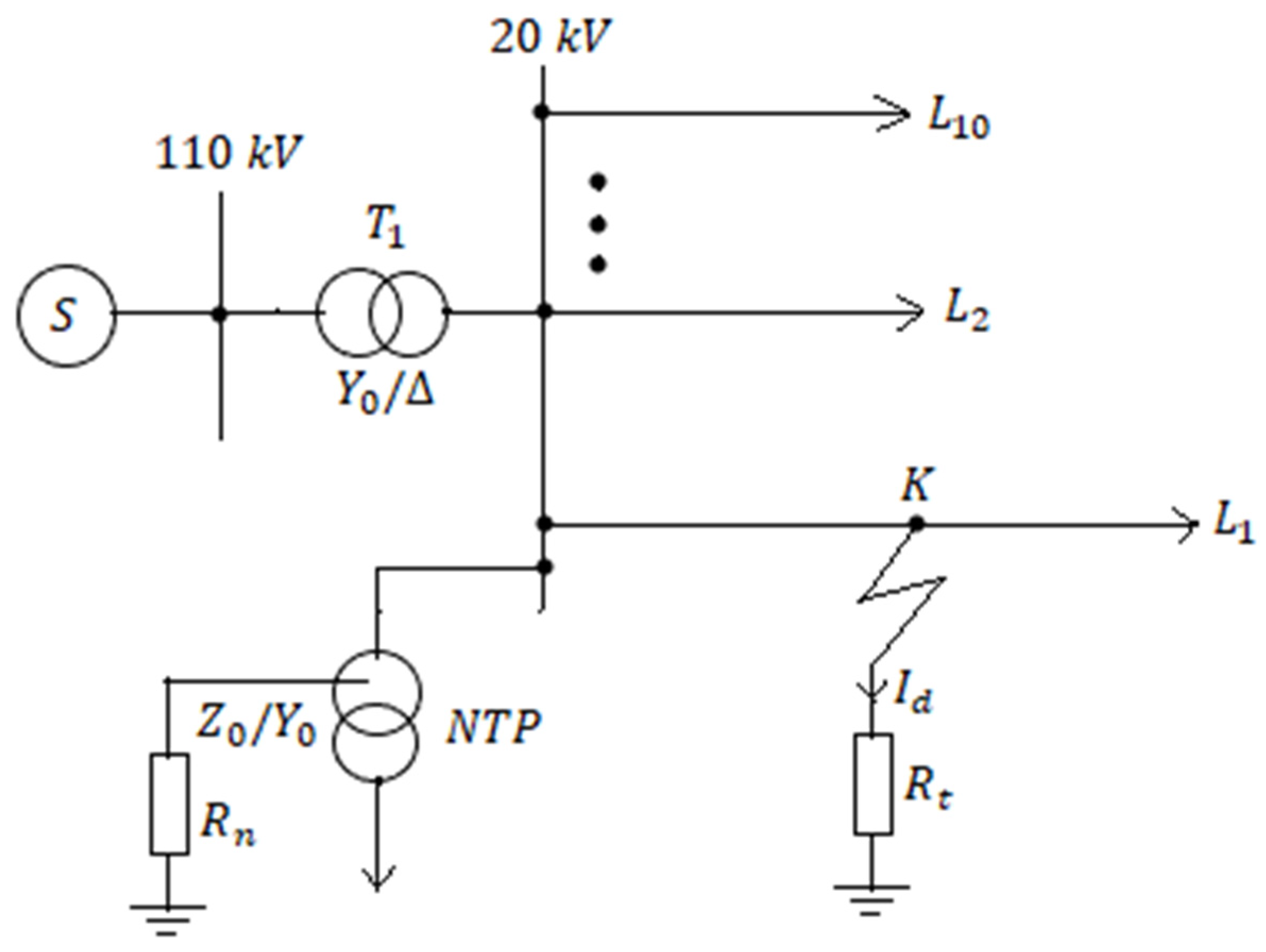
  • S—power source, considered source of infinite power (110 kV system);
  • T1—110/20 kV transformer (nominal apparent power 25 MVA, wye (Y0) connection on the 110 kV side and delta (∆) on the 20 kV side);
  • NTP—the own utilities transformer, with a zig-zag connection with neutral for the primary and a wye with neutral for the secondary, transformer also used to create the artificial neutral point of the 20 kV electrical network (nominal apparent power 600 kVA);
  • L 1 —faulted line phase–ground;
  • L 2 ,…, L 10 —20 kV lines without fault (the number of fault-free lines supplied from medium voltage bus bars is 9);
  • R n —the resistor used to connect the neutral of the medium voltage electrical network to ground and limited value of fault current for phase-to-ground fault;
  • R t —fault resistance;
  • K—the location of the phase-to-ground fault;
  • I d —single-line-to-ground fault current.
It is considered that the zero-sequence voltage of the 20 kV bars in the transformer station is in phase with the plus sequence voltage and its effective value changes from 0 to 1000 V, which corresponds to an asymmetry coefficient of the three-phase system of the phase voltages of the 20 kV bus bars in the transformer station belonging to the closed range [0–8.7%].
In insulating materials, including the insulation of medium voltage electrical networks, located in an electric field, active power losses occur. For this reason, the electrical scheme equivalent to a real capacitor consists of an ideal capacitor connected in parallel with an ideal resistor (Figure 2a) [27]. This scheme is also valid for the electrical capacity between the phase conductors of the medium voltage power line and ground. From the phasor diagram shown in Figure 2b it can be seen that the phase shift angle between the capacitive current ( I c   ) and the voltage U p h is (90°−δ). The angle δ represents the loss angle of the dielectric material [27]. The insulation state of the 20 kV network is characterized by the tangent of the loss angle (δ). If the insulation is perfect, then the tangent of the loss angle is equal to zero, and the zero-sequence impedance of the 20 kV network is purely capacitive. If the insulation of the medium voltage network deteriorates, then the tangent of the loss angle increases. In this paper, the maximum value of the tangent of the loss angle of 0.105 was considered. In the case of 20 kV cable power lines, the active component of the capacitive current is higher than that of overhead power lines. The total capacitive current of the 20 kV network, shown in Figure 1, is 102.5 A. This value was determined experimentally.
In the mathematical models presented in the literature for the calculation of the single line-to-ground fault current in the medium voltage electrical networks, the phase voltage system of the medium voltage bars in the transformer station is considered to be symmetrical. In reality, in most cases this voltage system is not perfectly symmetrical. Moreover, the rules in force accept that when the zero-sequence components represent less than 5% of the sequence components, the three-phase system is considered symmetrical. In the case of faults where the resistance at the fault location ( R t in Figure 1) is very high—over 1 kΩ—the zero-sequence of voltages before the fault occurs influences the current value through the resistor ( R n Figure 1) that connects the neutral point of the medium voltage network to ground. For this reason, the paper presents a mathematical model that also takes into account the zero-sequence component of the phase voltages of the medium voltage bars in the transformer station before the defect occurs (noted U e 0 in Figure 3). The paper justifies the fact that the proposed mathematical model is superior to those presented in the literature. The calculation with a higher precision of the current through the resistor that connects the null of the medium voltage network to earth (resistance R n in Figure 1) allows the appropriate regulation of the protections that detect phase-to-earth defects through very high resistance.
The R i n   resistance in Figure 2a takes into account the active power losses in the insulation of all medium voltage lines connected to the same medium voltage bus bar system in the transformer station. If the insulation of the medium voltage network is perfect, the resistance of the R i n becomes infinite. As the network insulation degrades, the value of the R i n resistance decreases and the loss angle δ increases, respectively. This is depicted in Figure 2a,b.
In Figure 2a,b the notations have the following meaning: U p h —the phase voltage of the medium voltage network; I c —the total capacitive current of the medium voltage network; I c r —reactive component of the total capacitive current of the medium voltage network;   I c a —active component of the total capacitive current of the medium voltage electrical network; C p h —phase–ground capacity of the medium voltage network; R i n —electrical resistance equivalent to active power losses in the insulation of the medium voltage electrical network. The use of the Petersen coil to treat the neutral of medium voltage electrical networks becomes inefficient if the active component of the current between the phase conductor of the network and the earth ( I c a in Figure 2b) increases. From Figure 2b the current   I c a is by (1):
I c a = I tan ( π 2 δ )
From (1) it is found that as the total capacitive current of the medium voltage network (denoted by I c in Figure 2a) increases, the value of the Ica current increases; for this reason, the value of the total capacitive current of the medium voltage electrical network must be taken into account when choosing the solution for neutral treatment.

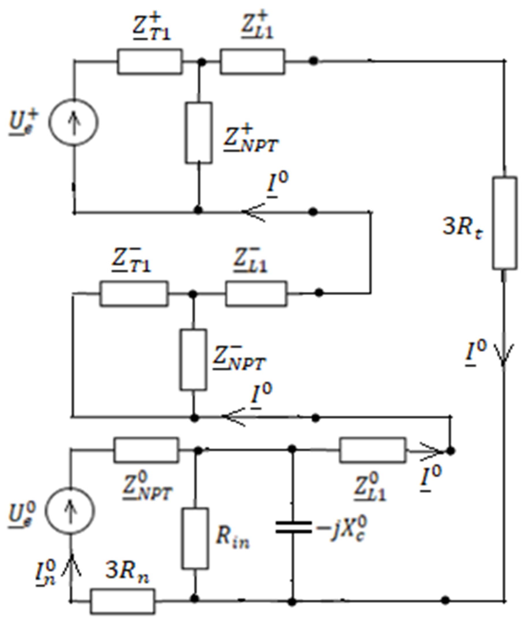
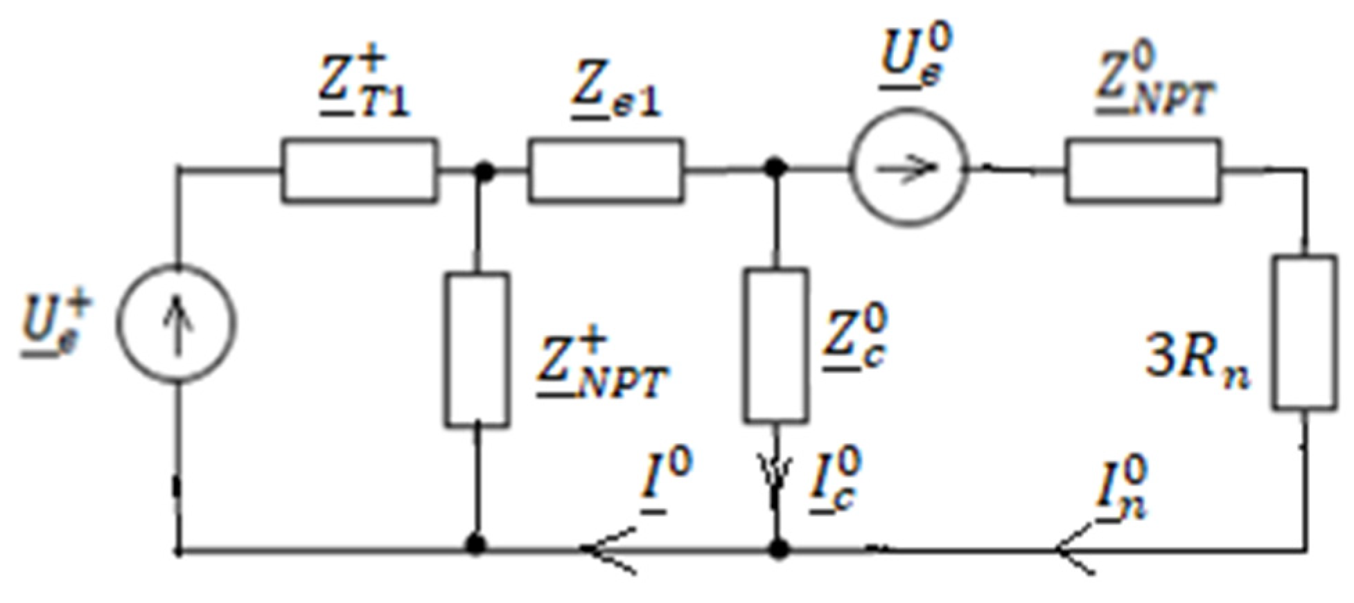
2. The Mathematical Model for the Analysis of a Single Phase-to-Ground Fault

The sequence components method is used to calculate the fault current. In the literature it is shown that in the case of a phase-to-ground fault the sequence networks are connected in series [13,14,15,16,17,18], [21] (pp. 474–507), [22] (pp. 327–334).
The meanings of the notations in Figure 3 are as follows:
  • U ¯ e + ,   U ¯ e 0 
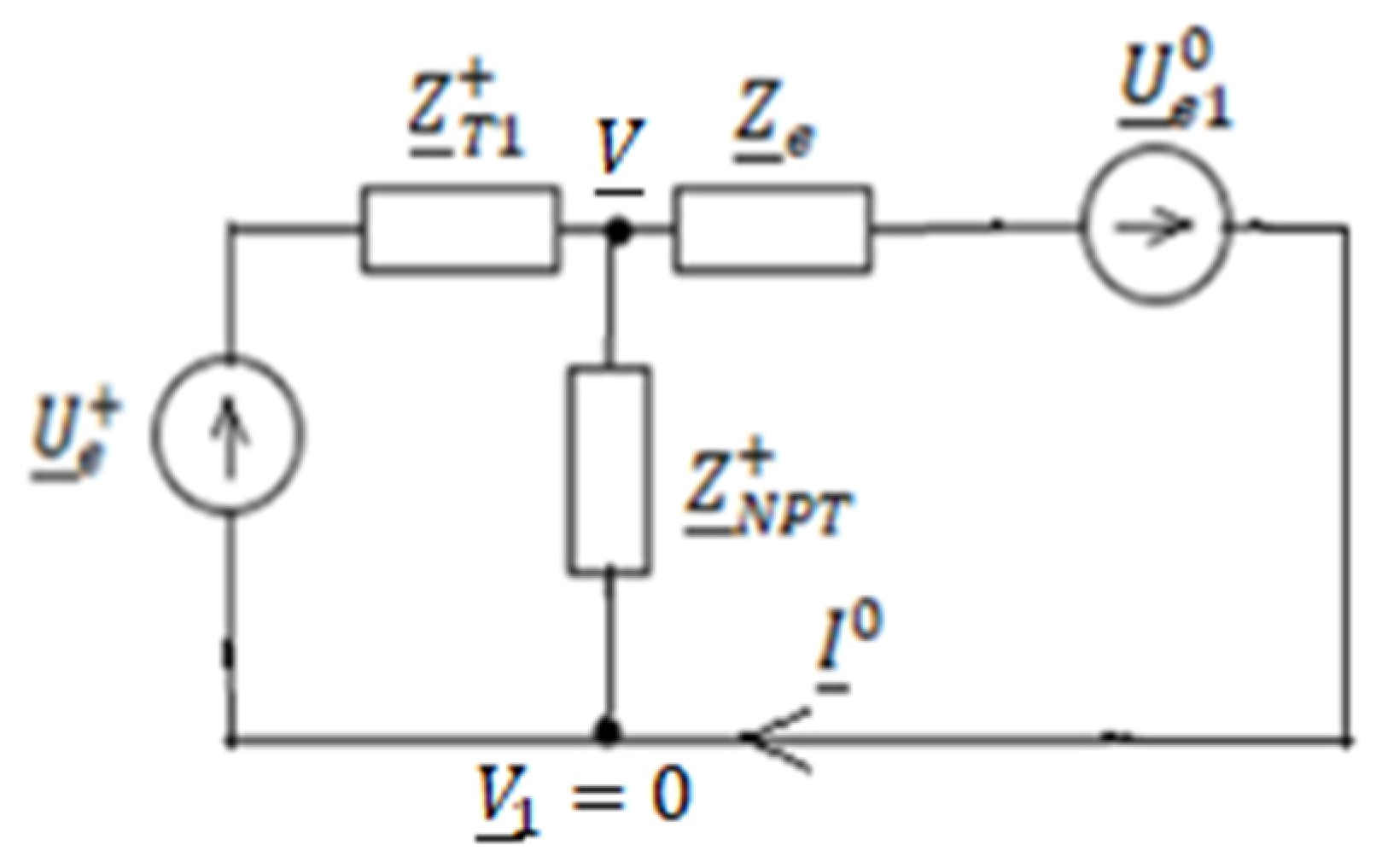
—the positive, respectively zero-sequence of electromotive forces of the equivalent voltage generator (Thevenin) corresponding to the 20 kV mains terminals, considered from the fault point;
  • Z ¯ T 1 + —positive-sequence impedance of transformer T1 in Figure 1;
  • Z ¯ T 1 —negative-sequence impedance of the transformer T1 in Figure 1;
  • Z ¯ L 1 + —positive-sequence impedance from the substation bus bars to the fault location on the faulted line (L1 in Figure 1);
  • Z ¯ L 1 —negative-sequence impedance from the substation bus bars to the fault location on the faulted line (L1 in Figure 1);
  • Z ¯ L 1 0 —zero-sequence impedance from the substation bus bars to the fault location on the faulted line (L1 in Figure 1);
  • Z ¯ N P T + —positive-sequence impedance of the utility transformer used to create the artificial neutral point of the 20 kV network;
  • Z ¯ N P T —negative-sequence impedance of the utility transformer used to create the artificial neutral point of the 20 kV network;
  • Z ¯ N P T 0 —zero-sequence impedance of the utility transformer used to create the artificial neutral point of the 20 kV network;
  • X c 0 
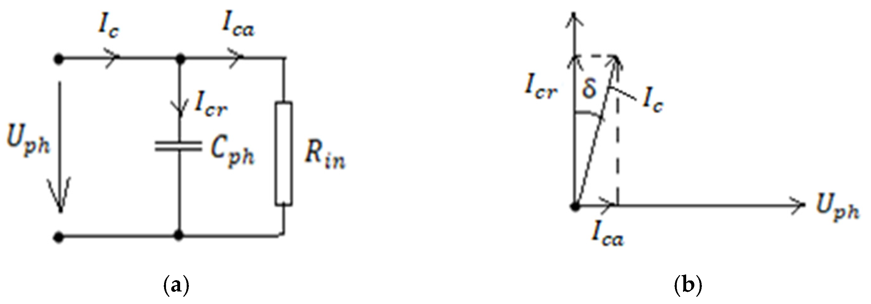
—zero-sequence capacitive reactance of electrical network with a nominal voltage 20 kV;
  • R i n —equivalent electrical resistance corresponding to active power losses in the insulation of the electrical network with a nominal voltage of 20 kV;
  • R t —resistance at the fault location;
  • R n —limiting resistor used to connect the 20 kV network neutral to ground.
For the calculation of the zero-sequence current, the simplified diagram from Figure 4 is considered.
The negative and zero-sequence network is reduced to a real voltage source that has the electromotive voltage U ¯ e 1 0 (Figure 4) and the internal impedance Z ¯ e (Figure 4). These parameters are expressed as a function of those of the medium voltage network (20 kV) using (2) and (4):
U ¯ e 1 0 = Z ¯ c 0 U ¯ e 0 Z ¯ c 0 + Z ¯ N P T 0 + 3 R n
where Z ¯ c 0 represents the zero-sequence impedance of the medium voltage network (20 kV). This impedance depends on the total capacitive current of the medium voltage network and the state of its insulation. This impedance is expressed as a function of the parameters of the medium voltage network using (3):
Z ¯ c 0 = R i n ( j X ¯ c 0 ) R i n j X ¯ c 0
The internal impedance of the equivalent zero-sequence source is expressed by (4):
Z ¯ e = Z ¯ e 1 + Z ¯ c 0 ( Z ¯ N P T 0 + 3 R n ) Z ¯ c 0 + Z ¯ N P T 0 + 3 R n
where the impedance Z ¯ e 1   is expressed by (5):
Z ¯ e 1 = Z ¯ L 1 + + Z ¯ L 1 + Z ¯ L 1 0 + 3 R t + Z ¯ T 1 Z ¯ N P T Z ¯ T 1 + Z ¯ N P T
For the calculation of the zero-sequence current, the node potential method is applied. Considering the potential V ¯ 1   in Figure 4 as being equal to 0, potential V ¯ from Figure 3 and Figure 4 is calculated using (7):
V ¯ ( 1 Z ¯ T 1 + + 1 Z ¯ N T P + + 1 Z ¯ e ) = U ¯ e + Z ¯ T 1 + U ¯ e 1 0 Z ¯ e
From Equation (6) the potential V ¯ is obtained:
V ¯ = U ¯ e + Y ¯ T 1 + U ¯ e 1 0 Y ¯ e Y ¯ T 1 + + Y ¯ N T P + + Y ¯ e
The admittances in (7) are expressed as a function of impedances as follows:
Y ¯ T 1 + = 1 Z ¯ T 1 + ,         Y ¯ N T P + = 1 Z ¯ N T P + ,     Y ¯ e + = 1 Z ¯ e        
The zero-sequence current ( I ¯ 0 ) is calculated using (9):
I ¯ 0 = V ¯ + U ¯ e 1 0 Z ¯ e = U ¯ e + Y ¯ T 1 + U ¯ e 1 0 Y ¯ e Y ¯ T 1 + + Y ¯ N T P + + Y ¯ e Y ¯ e + U ¯ e 1 0 Y ¯ e
The zero-sequence current ( I ¯ n 0 ) flowing through the limiting resistor is determined from Figure 5, its expression being given in (10):
I ¯ n 0 = U ¯ e 1 0 + Z ¯ c 0 I ¯ 0 Z ¯ c 0 + Z ¯ N P T 0 + 3 R n
The zero-sequence capacitive current ( I ¯ c 0 ) of the medium voltage network is obtained by applying Kirchhoff’s first theorem in the diagram in Figure 5:
I ¯ c 0 = I ¯ 0 I ¯ n 0
The zero-sequence voltage ( U ¯ b 0 ) of the medium voltage bus bars (20 kV) is expressed by the relation:
U ¯ b 0 = Z ¯ c 0 I ¯ c 0

3. Numerical Results

Numerical calculations and graphical representations were performed using the Matlab and Mathcad programming environment In order to determine how the zero-sequence voltage of the 20 kV bus bars from the transformer station ( U e 0 ) before the occurrence of the single-phase fault, the resistance to the fault location, and the insulation state influences the effective value of the currents I 0 ,   I n ,   0   I c 0   the single line diagram from Figure 1 was considered. The sequence parameters of its elements are shown in Table 1.
Zero-sequence parameters of the 20 kV network that depend on the state of the insulation, given by the tangent of the loss angle (δ—Figure 2b), are presented in Table 2.

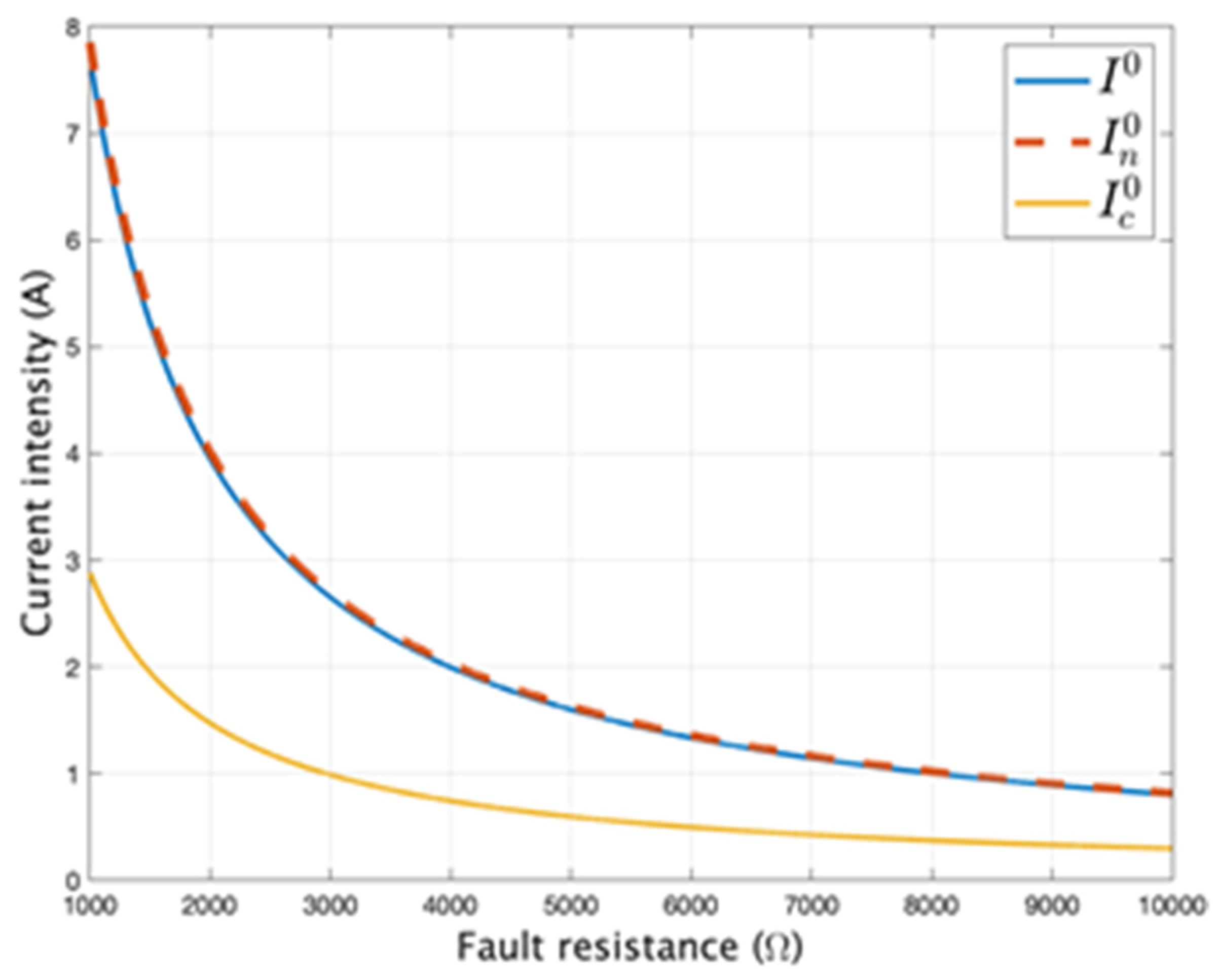
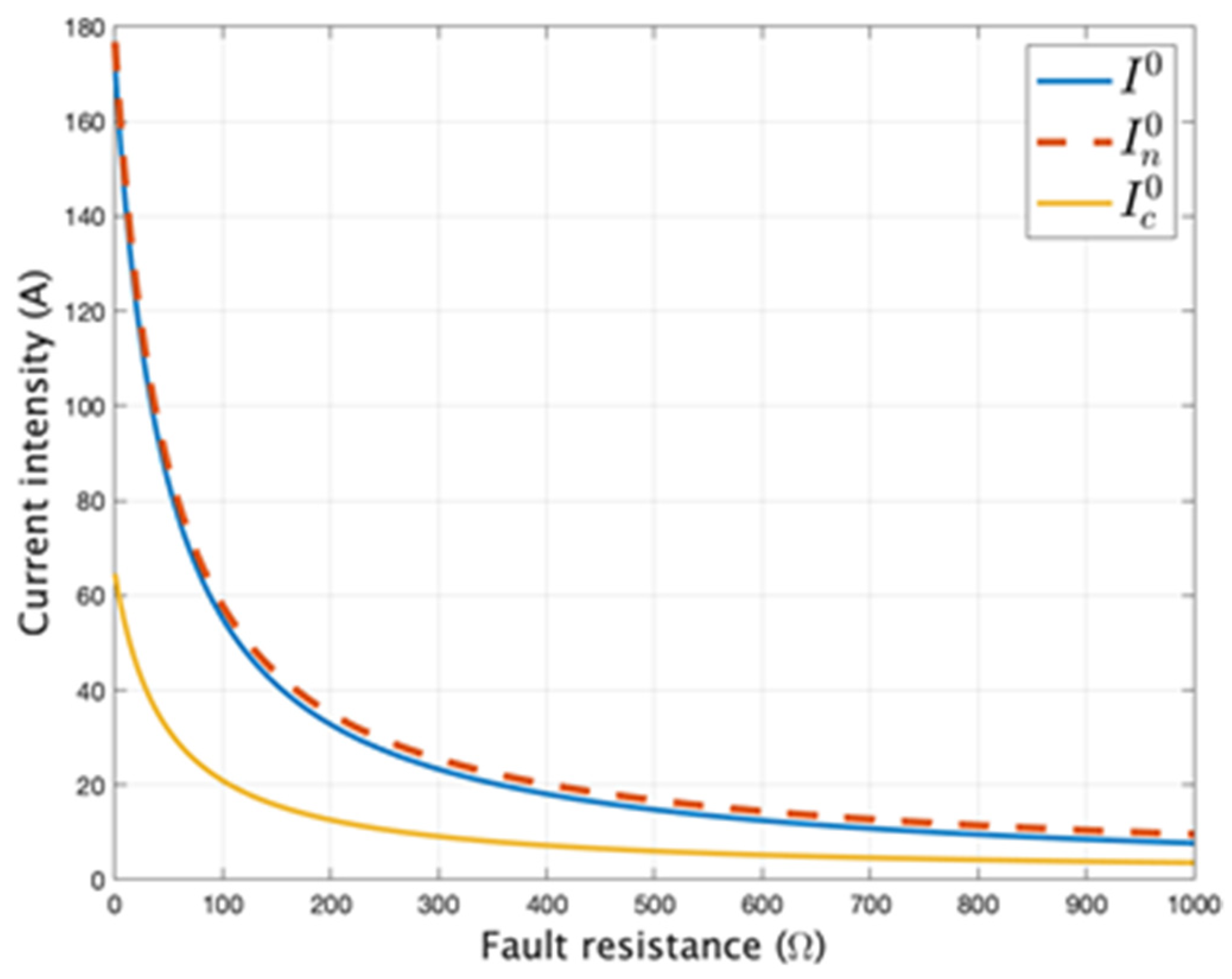
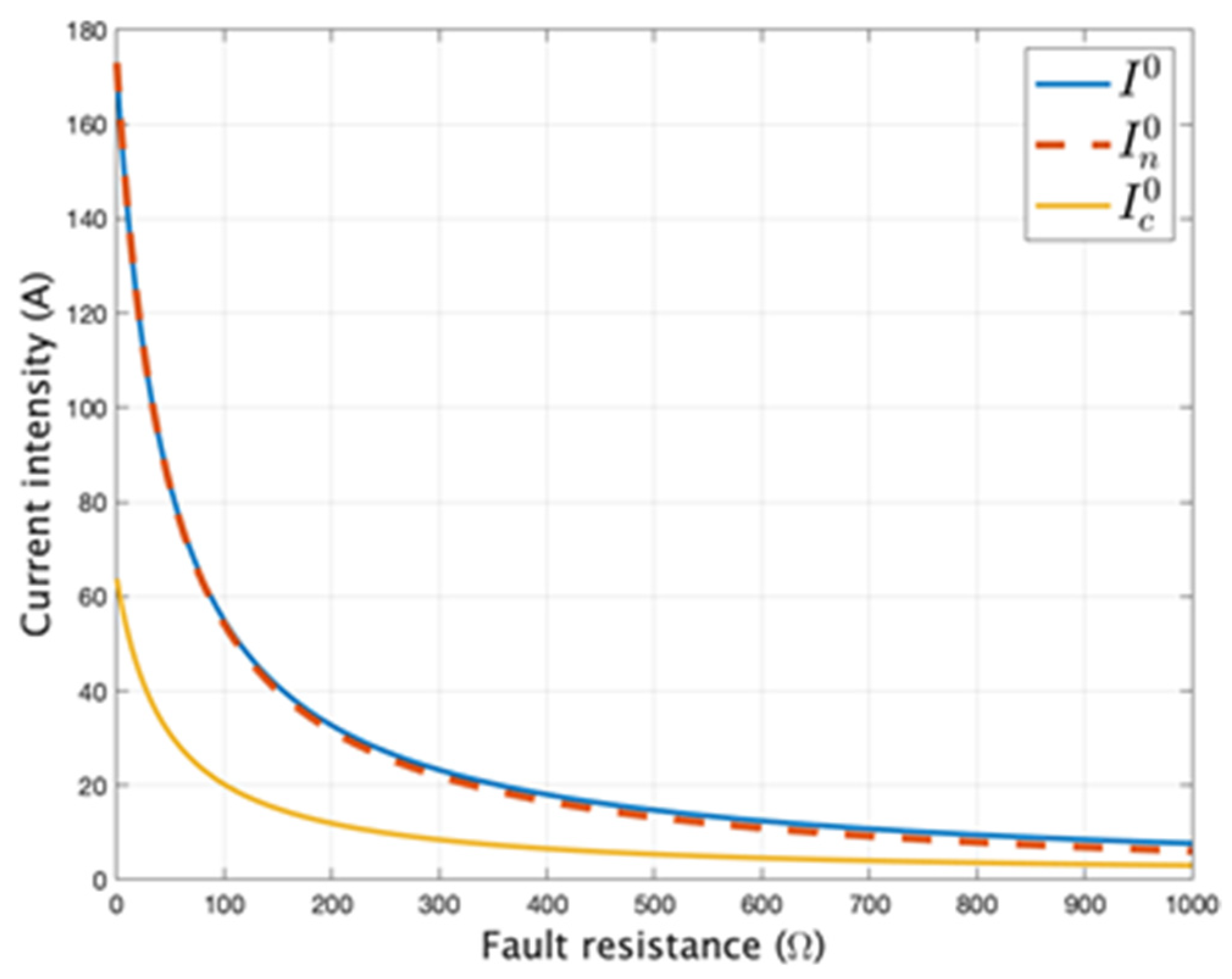
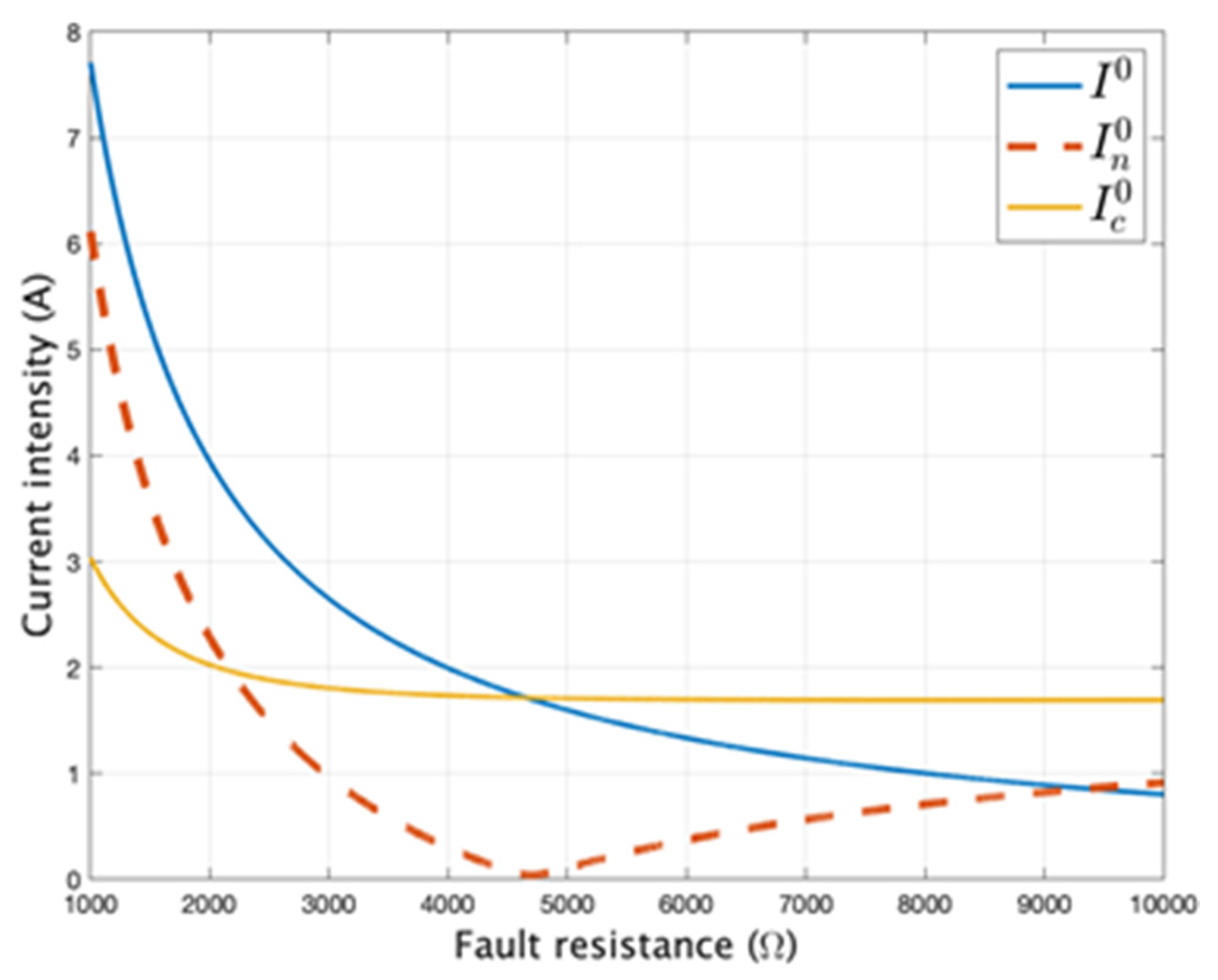
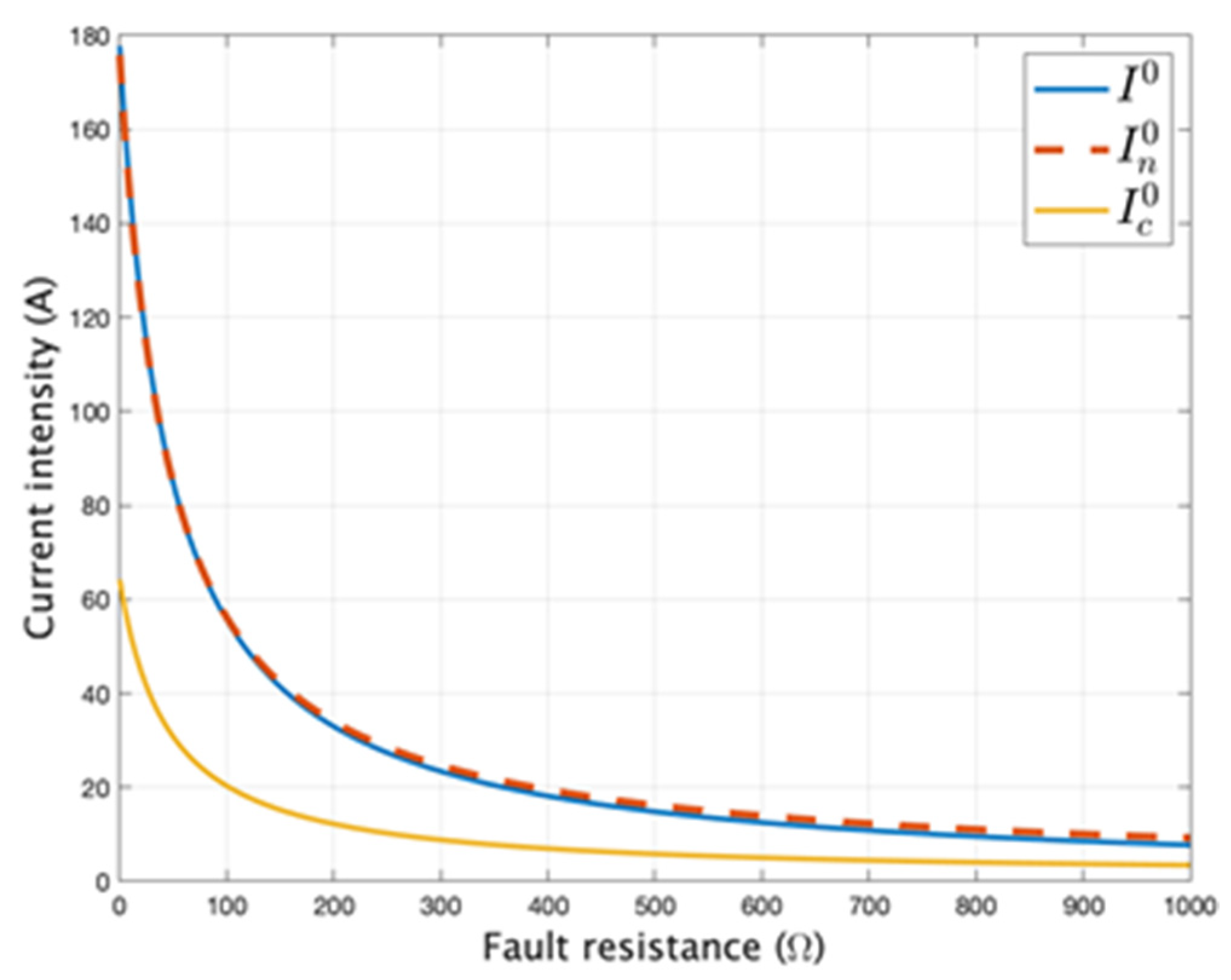
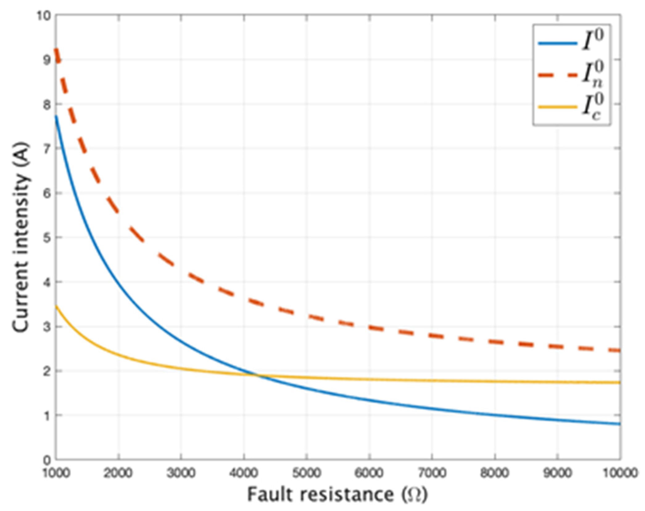
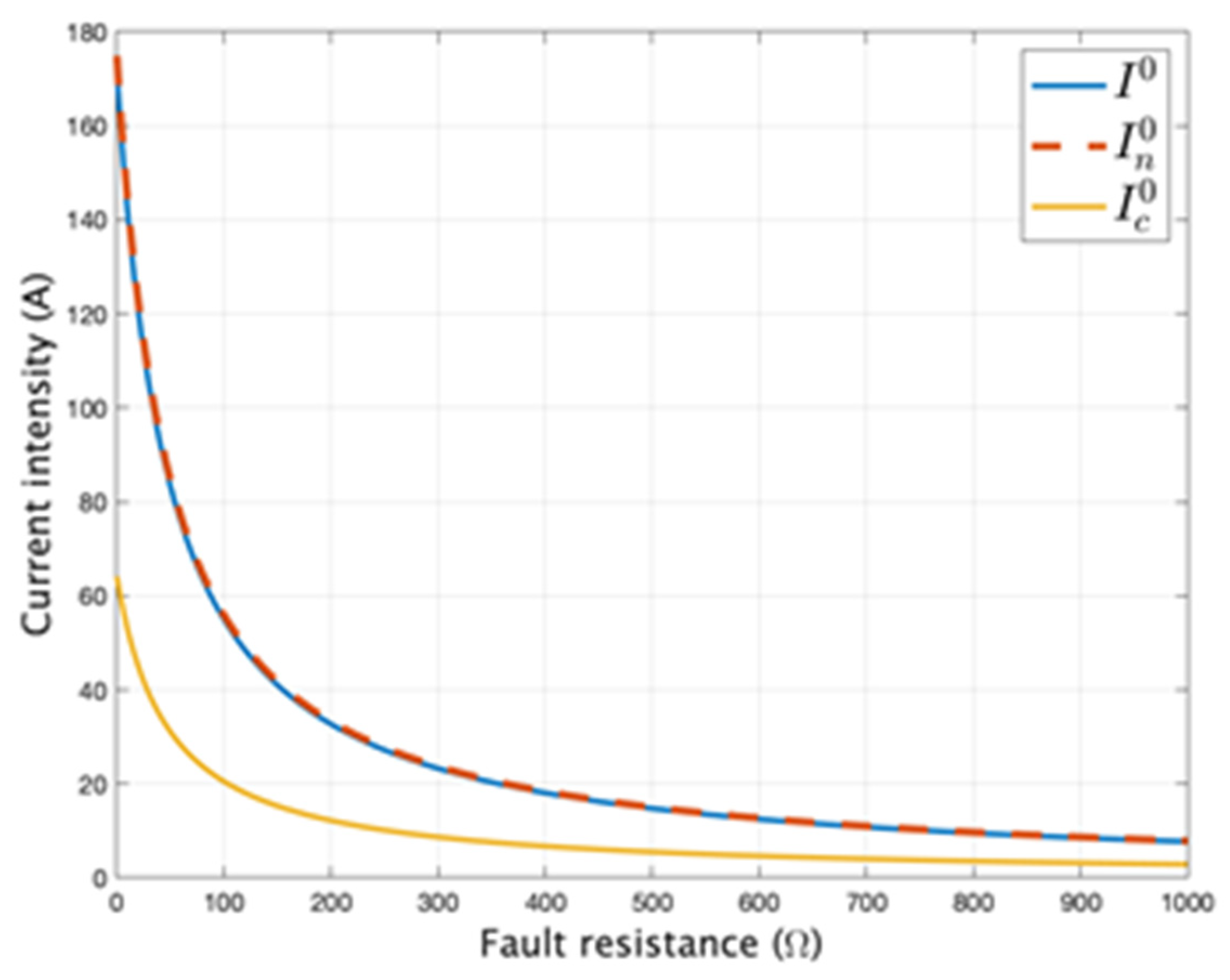
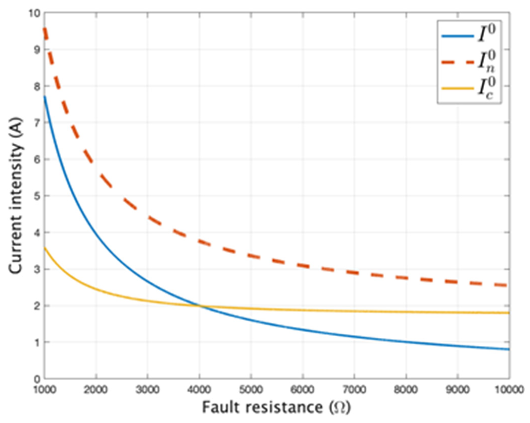
3.1. The Dependence of the Effective Value of the Currents as a Function of Fault Resistance R t

For the analysis of the dependence of the effective values of the currents I 0 ,   I n 0 ,   I c 0 as functions of fault resistence, it is considered that the value of this parameter ranges from 0 to 10,000 ohms, while the effective value of the zero-sequence voltage ( U e 0 ) is either 0, 575 V, or −575 V are and the tangent of the insulation loss angle (tanδ) 0.105 and 0, respectively.
The positive-sequence electromotive forces U e + has the value 11,547 V. The range interval of the fault resistance was divided in two, from 0 to 1000 ohms and from 1000 to 10,000 ohms. The obtained results are presented in graphical form in Figure 6, Figure 7, Figure 8, Figure 9, Figure 10, Figure 11, Figure 12 and Figure 13.

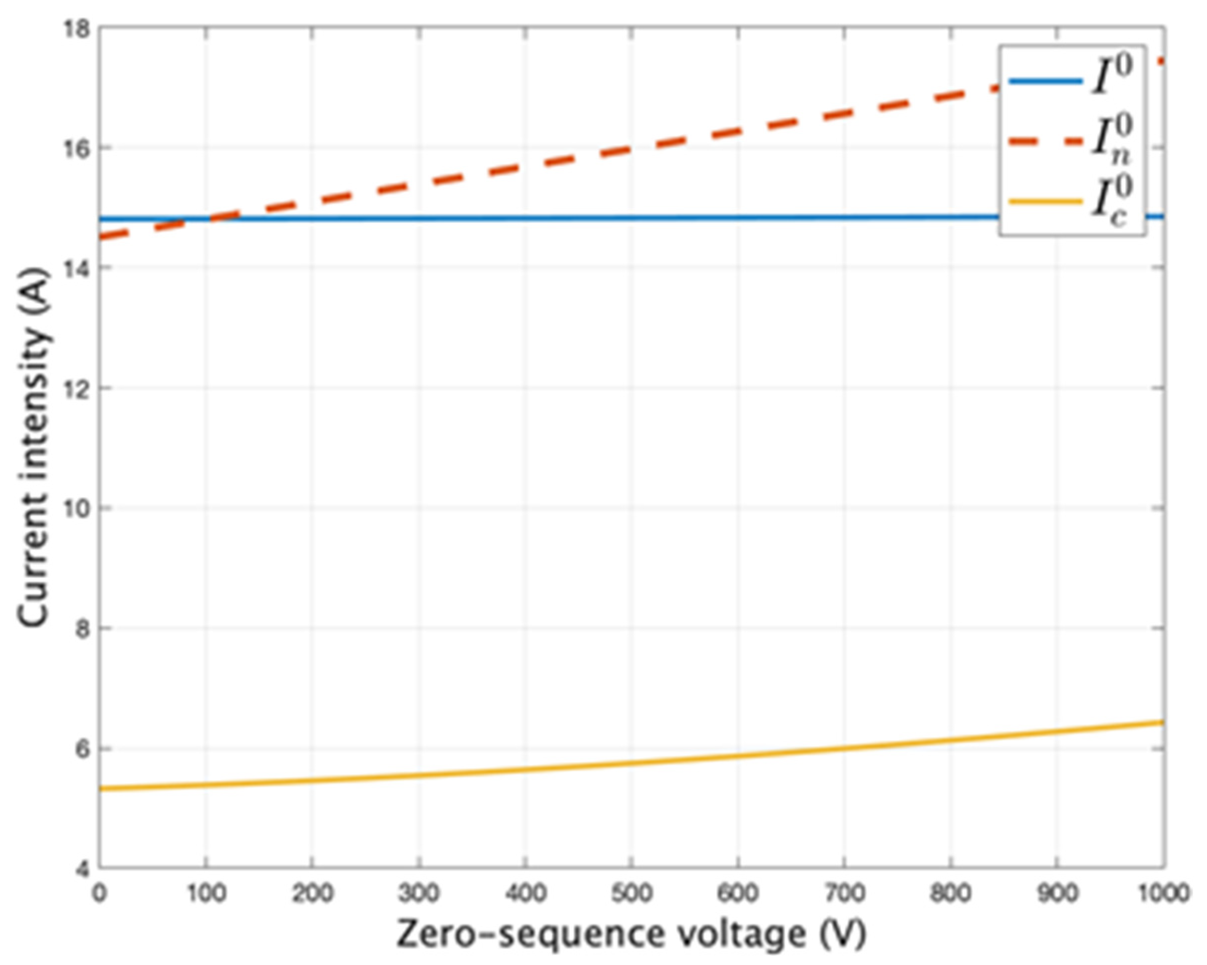
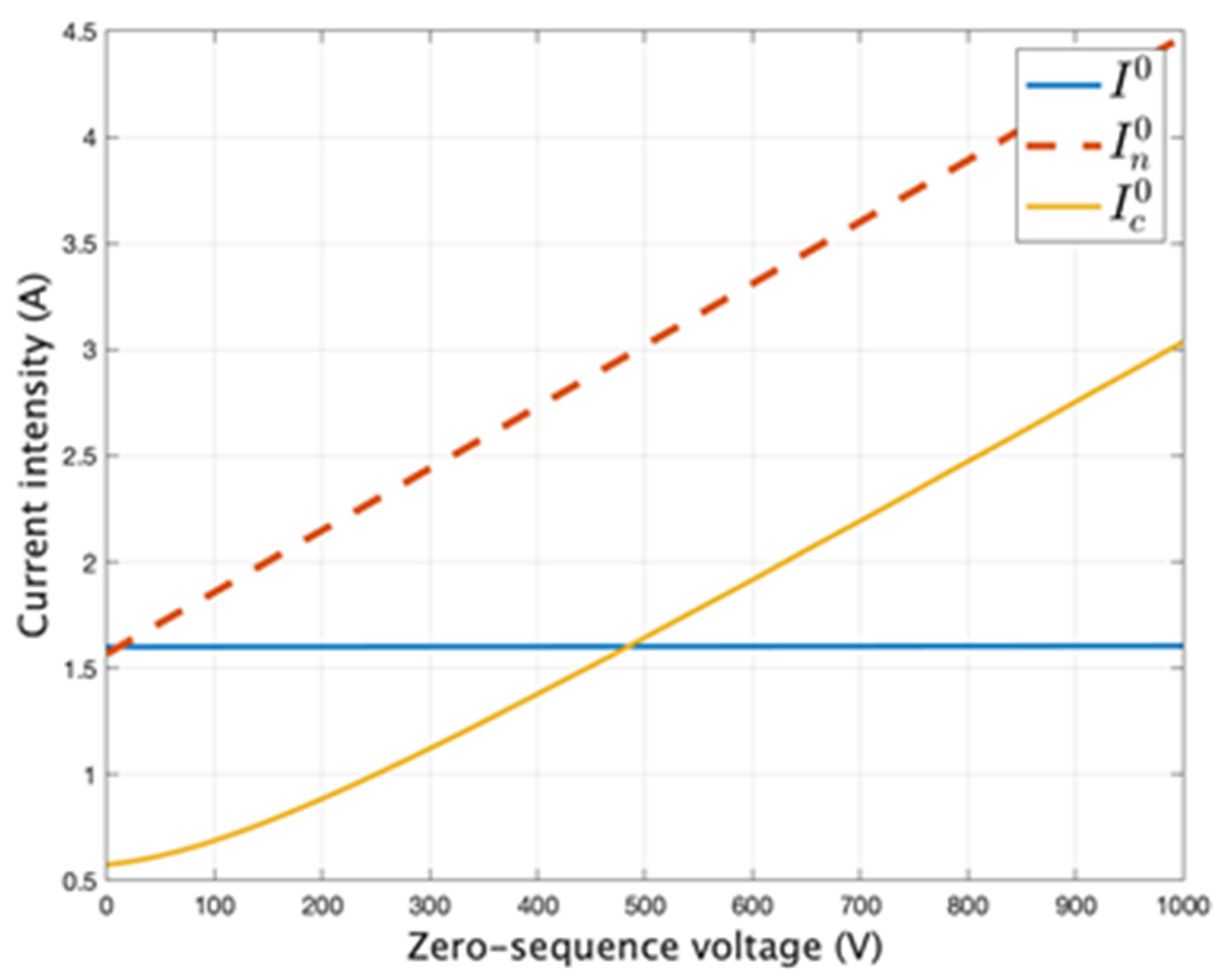
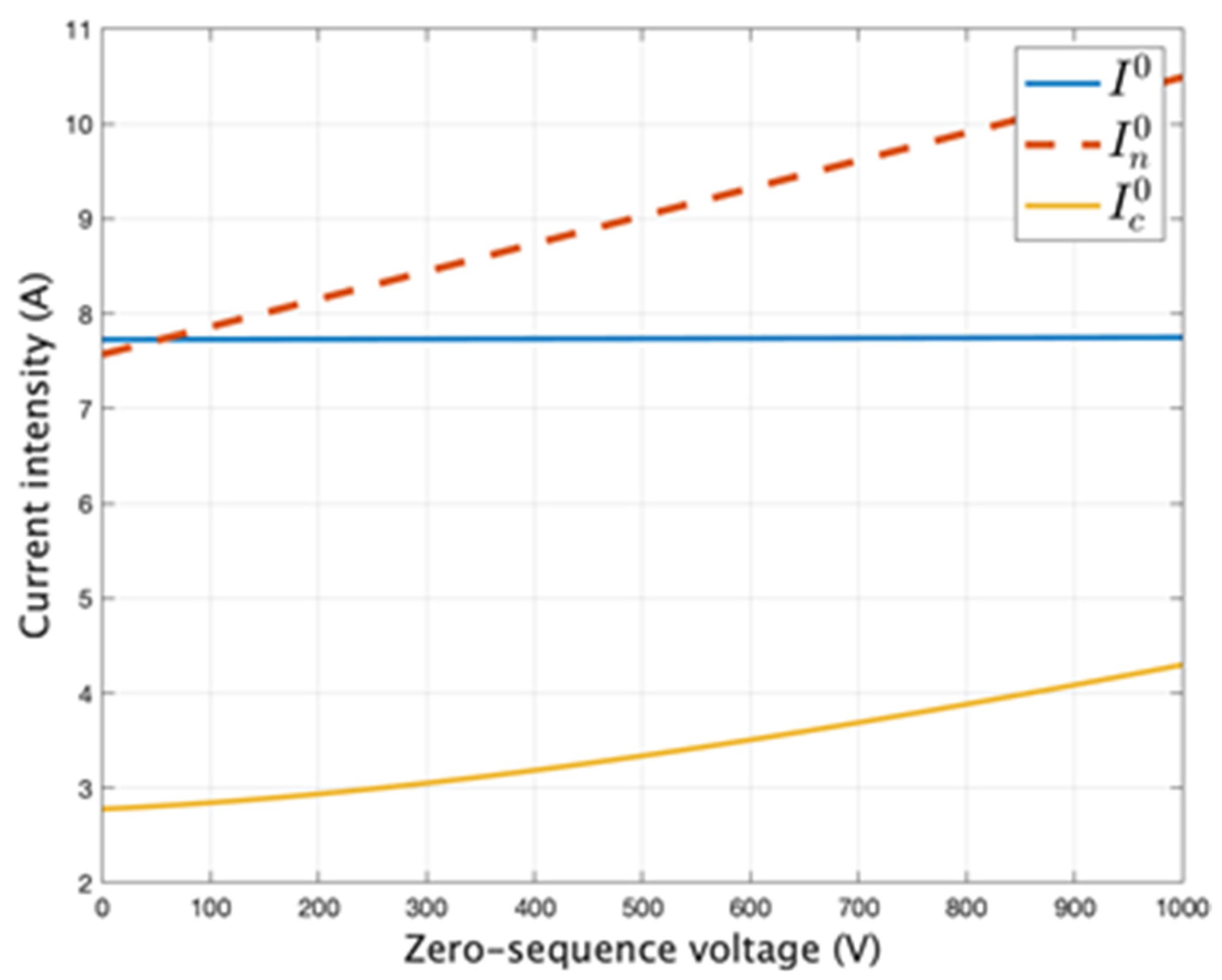
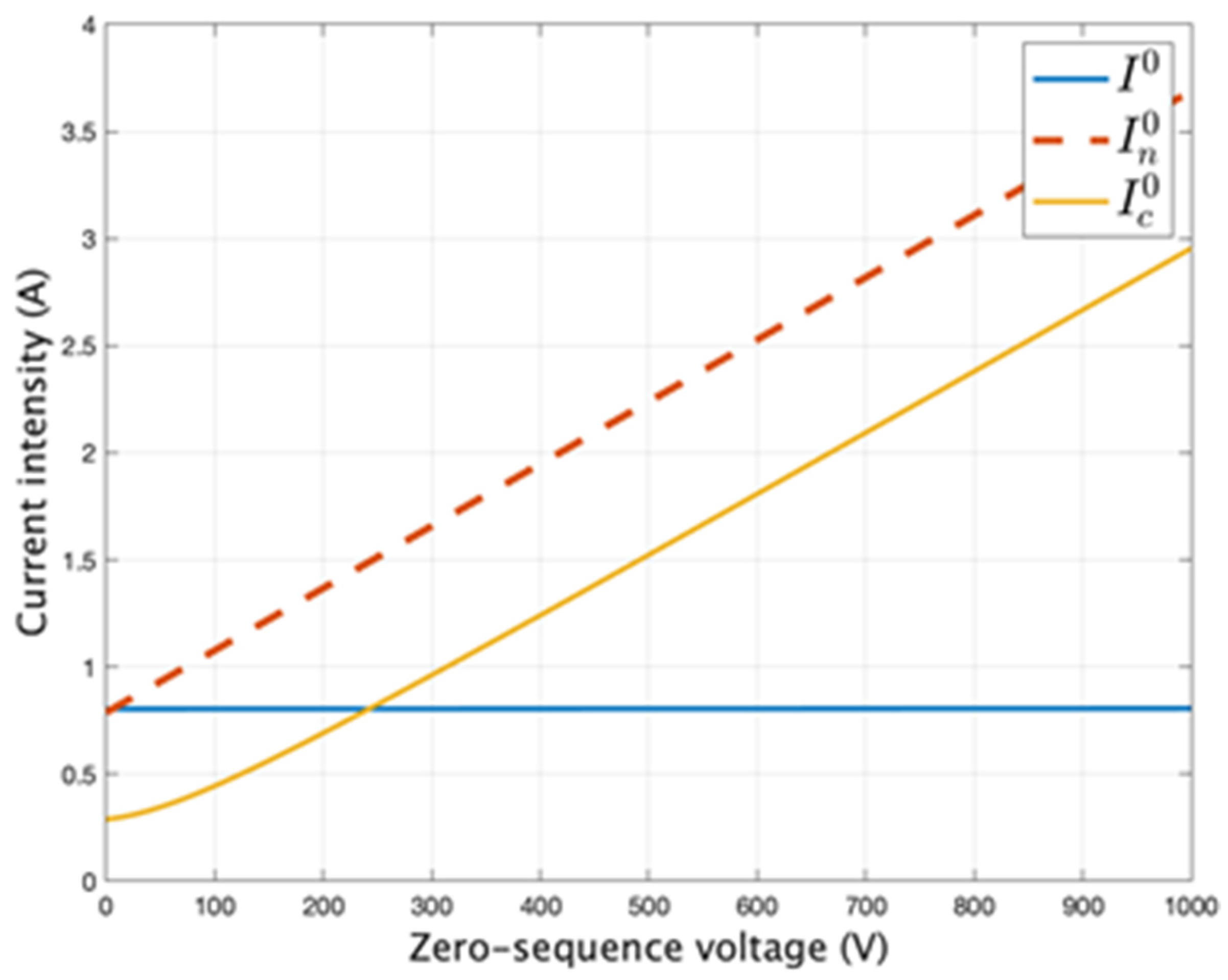
3.2. The Dependence of the Effective Value of the Currents as a Function of Zero-Sequence U e 0

For the analysis of the dependence of the currents I 0 ,   I n 0 ,   I c 0 as functions of the zero-sequence voltage of the 20 kV bars in the transformer station, it is considered that its effective value changes from 0 to 1000 V. Values of 500 Ω, 1000 Ω, 5000 Ω, 10,000 Ω were considered for the resistance to the fault location. The dependence of the effective value of the currents I 0 ,   I n 0 ,   I c 0 is shown in Figure 14, Figure 15, Figure 16 and Figure 17.

4. Discussion

From Figure 6 and Figure 7 it can be seen that in the case of a single line-to-ground fault the value of the current through the limiting resistance ( R n ) is practically equal to the fault current regardless of the value of the resistance at the fault place ( R t ) if U e 0 = 0 and the insulation is perfect (δ = 0).
From Figure 9 it is found that when U e 0 = 575   V , (5% of U e + ), for R t = 1000   Ω the value of the current through the limiting resistor ( R n ) is 9.6 A, and that of the fault current is 7.7 A. If R t = 10,000   Ω the value of the current through the limiting resistor ( R n ) is 2.6 A, and that of the fault current is 0.8 A. Therefore, if we consider that the two currents are equal, an inadmissible error is made.
From Figure 11 results it can be seen that when U e 0 = 575   V , (−5% of U e + ), for R t = 1000   Ω the value of the current through the limiting resistor ( R n ) is 6.2 A, and that of the fault current is 7.8 A. If R t = 10,000   Ω the value of the current through the limiting resistor ( R n ) is 0.9 A, and that of the fault current is 0.8 A. Therefore, even in this case the two currents cannot be considered equal, because they are very different. From Figure 11 it can be seen that the current value through the resistor R n is zero for R t 4800   Ω . If a fault of the single line-to-ground is detected by measuring the value of the current through R n , in such a case it cannot be detected. This result is important in the operation of medium voltage electrical networks.
From Figure 13 it can be seen that that when the insulation of the 20 kV network is no longer perfect (tgδ = 0.105, the delta angle is 6°) and U e 0 = 575   V (5% of U e + ), if the resistance at the fault location is R t = 1000   Ω , the value of the current through the neutral grounding resistance R n is 9.2 A, and the value of the fault current is 7.8 A. If R t = 10,000   Ω , the value of the current through the neutral grounding resistance R n is 2.5 A, and the value of the fault current is 0.8 A.
Comparing the results from Figure 9 with those from Figure 13 it is found that the values of the currents through R n differ by 4.17%, and the values of the fault current are practically the same. Therefore, for the calculation of the fault current the insulation of the medium voltage network can be considered perfect (δ = 0), and for the calculation of the current through R n the network insulation cannot be considered perfect.
From Figure 8, Figure 10 and Figure 12 it is found that for resistors at the fault location ( R t ) with values less than 500 ohms, the value of the current through the limiting resistor R n is practically equal to that of the fault current.
Figure 15, Figure 16 and Figure 17 show that the value of the fault current ( I d = 3 I 0 ) depends insignificantly on the value of the zero-sequence voltage of the medium voltage bars in the absence of the phase-to-earth fault, which is no longer true for the current in the neutral grounding resistor of the medium voltage network ( R n from Figure 1), respectively, for the capacitive current of the medium voltage network with a neutral grounding resistor. From Figure 14 it is found that for R t = 500   Ω and the loss angle of the insulation δ = 6°, the current I n 0 increases from 14.5 A when U e 0 = 0 to 16 A when U e 0 = 500 V (represents 4.33% of U e + ), meaning an increase of 9.37%. From Figure 15 it is found that for R t = 1000   Ω , the current I n 0 increases from 7.6 A when U e 0 = 0 to 9 A when U e 0 = 500   V (represents 4.33% of U e + ), meaning an increase of 15.56%. From Figure 16 it is found that for R t = 5000   Ω the current I n 0 increases from 1.54 A when U e 0 = 0 to 3.2 A when U e 0 = 0 = 500 V (represents 4.33% of U e + ), meaning an increase of 51.86%. From Figure 17 it is found that for R t = 10,000   Ω the current I n 0 increases from 0.81 A when U e 0 = 0 to 2.48 A when U e 0 = 500 V (represents 4.33% of U e + ), meaning an increase of 67.34%. Therefore, not taking into account the voltage U e 0 in the calculation of this current leads to inadmissible errors. In order to evaluate how the effective value of the zero-sequence voltage of the medium voltage bus bars in normal operation influences the effective values of the zero-sequence components of the current in the limiting resistor I n 0 in %, the difference between the effective values of these currents for U e 0 = 0 ( I n 0 (0)) and for U e 0 = 575   V ( I n 0 (575)), respectively, are calculated using (13). U e 0 = 575   V corresponds to an asymmetry coefficient of 5%; hence, the three-phase system of phase voltages of the 20 kV bus bars in the transformer station is accepted as symmetrical.
ε % = I n 0 ( 575 ) I n 0 ( 0 ) I n 0 ( 575 ) 100
This difference was calculated considering the tangent of the perfect 20 kV grid insulation loss angle equal to 0 (perfect insulation) for tanδ = 0 and tanδ = 0.105, respectively. The results are presented in Table 3 and Table 4.
Comparing the results presented in Table 3 and Table 4 it is found that the effective value of the current intensity in the limiting resistor is strongly influenced by the effective value of the zero-sequence voltage of the 20 kV bus bars in the transformer station, regardless of the state of insulation. Therefore, it is necessary that the calculation of the currents I 0 ,   I n 0 ,   I c 0 takes into account the value of the voltage U e 0 . Neglecting it in the calculation leads to very large errors, especially if the resistance at the fault location is bigger than 1000 ohms. According to Figure 5 and Figure 6 and Figure 7 and Figure 8 when the resistance at the fault site is less than 500 ohms, the influence of the voltage U e 0 on the current I n 0 is below 5% and can be neglected.
In order to ascertain the influence of the insulation state of the medium voltage network on the value of the current I n 0 we compare the results from Figure 8, where tanδ = 0, with those from Figure 12 and Figure 13, where tanδ = 0.105. The difference between the two values of the current I n 0   is calculated using (14). The results are presented in Table 5.
ε % = I n 0 ( t g δ = 0 ) I n 0 ( t g δ = 0.105 ) I n 0 ( t g δ = 0 ) 100
Table 5 shows that the influence of the insulation state of the medium voltage network on the current I n 0     is much lower than the influence of the voltage U e 0 . The difference between the values of the current I n 0   when the network insulation is perfect (tanδ = 0) and imperfect (tanδ = 0.105), when U e 0 = 575 V and R t   = 10,000 Ω, is 8.72%. According to Table 3 and Table 4 the difference between the values of the current I n 0 for U e 0 = 575 V and U e 0 = 0, if R t   = 10,000, is about 79%. As a result, in the current calculation of I n 0 , the state of the insulation of the medium voltage network can be neglected, but the value of the voltage U e 0 cannot be neglected even if its value represents less than 5% of U e + .

5. Conclusions

The main conclusions resulting from the study are:
(a) According to Figure 6, Figure 8, Figure 10 and Figure 12, for fault resistance (Rn) values smaller than 500 Ω , the current through the limiting resistor can be calculated using the model presented in the literature, and the zero-sequence voltage of the medium voltage bus bars in normal conditions can be neglected. The error computed using (13) is smaller than 6.24%, which is acceptable considering the degree of precision for the values of the parameters from Figure 3.
(b) Figure 14, Figure 15, Figure 16 and Figure 17 show that the zero-sequence voltage of the medium voltage bus bars does not significantly influence the values of the zero-sequence current at the fault location; thus, implicitly the ground fault current can be neglected in the calculation. For example, for a perfect insulation (loss angle of 0°) and a ratio of U e 0 to U e + + of 5%, the error is 4.61%, whereas for a loss angle of 6° (tanδ = 0.105) and a ratio of U e 0 to U e + of 5%, the error is 4.23%. Therefore, the ground fault current can be calculated using the model presented in the literature.
(c) According to Table 3 and Table 4, if the fault resistance (Rn) values range from 1000 to 10,000 ohms, the calculation of the current through the limiting resistor using the model presented in the literature leads to unacceptable errors. For example, if Rn is equal to 1000 ohms and tanδ is 0, the error given by (13) is 22.43%, whereas if Rn is equal to 10,000 ohms and tanδ is 0.105, the error is 78.89%, hence the need for the calculation of the currents I 0 ,   I n 0 ,   I c 0 that takes into account the value of the voltage U e 0 . In this case, in resistor grounded medium voltage networks where single line-to-ground faults are detected by measuring the effective value of the current flowing through the limiting resistor, it is necessary to use the model presented in this paper.
(d) The numerical results from the model presented in this paper indicate that, in resistor grounded medium voltage networks, it is necessary to consider the zero-sequence voltage of the medium voltage bus bars in normal condition, thus ensuring the correct setting of the protective relay used to detect single line-to-ground faults under all circumstances.
(e) Regardless of the model used for the calculation of the effective values for I 0 ,   I n 0 ,   I c 0 , the maximum differences between these values are obtained either when U e 0 is 5% of U e + and the offset is 0° or when U e 0 is −5% of U e + and the offset is 180°.
(f) The difference between the effective values of the current flowing through the limiting resistor, if the offset between U e 0 and U e + is either 0° or 180° and the fault resistance ranges from 0 to 10,000 ohms, for both δ = 0° and δ = 6°, is smaller than 8.45%, which is acceptable considering the degree of precision for the values of the parameters from Figure 3. This leads to the conclusion that the U e 0 and U e + can be considered in phase for the calculation of this current.
(g) The influence of the insulation state on the current through the limiting resistor is significantly lower in resistor grounded medium voltage networks than in resonant grounded networks. For example, according to Figure 6, Figure 7, Figure 12 and Figure 13, for fault resistance values of 0 and 5000 ohms, the difference between the effective values of the zero-sequence current at the fault location is 0.391%, for δ = 0°, and 4,23%, for δ = 6°, whereas in a resonant grounded medium voltage network, it is up to 38.1% [13]. Therefore, in resistor grounded medium voltage networks, the loss angle δ can be considered equal to 0°, which corresponds to an infinite Rin in Figure 3.

Author Contributions

Conceptualization, D.T. and M.G.; methodology, D.T., M.V., A.M. and D.V.; software, D.T., I.T. and C.S.; validation, D.T., C.S. and M.G.; formal analysis, M.G., I.T., A.M., and D.V.; investigation, D.T. and M.V.; resources, D.T. and M.G.; data curation, D.T.; writing—original draft preparation, C.S.; writing—review and editing, D.T.; visualization, M.G.; supervision, D.T.; project administration, D.T.; funding acquisition, M.G. All authors have read and agreed to the published version of the manuscript.

Funding

This research received no external funding.

Institutional Review Board Statement

Not applicable.

Informed Consent Statement

Informed consent was obtained from all subjects involved in the study.

Data Availability Statement

The data presented in the paper, obtained by calculation, respectively experimentally were not published, which is why data sharing is not applicable to this article.

Conflicts of Interest

The authors declare no conflict of interest.

References

  1. Topolanek, D.; Lehtonen, M.; Adzman, M.R.; Toman, P. Earth fault location based on evaluation of voltage sag at secondary side of medium voltage/low voltage transformers. IET Gener. Transm. Distrib. 2015, 9, 2069–2077. [Google Scholar] [CrossRef] [Green Version]
  2. Guo, Z.; Yao, J.; Yang, S.; Zhang, H.; Mao, T.; Duong, T. A new method for non-unit protection of power transmission lines based on fault resistance and fault angle reduction. Int. J. Electr. Power Energy Syst. 2014, 55, 760–769. [Google Scholar] [CrossRef]
  3. Ukrainicev, A.; Nagy, V.; Nagy, I.; Sarry, S.; Chmihaloy, G. Analysis of the Functioning of the Earth Fault Protection with Active Influence on Electrical Grid. In Proceedings of the 9th International Scientific Symposium on Electrical Power Engineering, Stará Lesná, Słowacja, 12–14 September 2017; pp. 418–421. [Google Scholar]
  4. Adzman, M.R.; Lehtonen, M. Estimation of Single Line to Ground Fault Location in Unearthed Medium Voltage Distribution Network. In Proceedings of the 13th International Scientific Conference Electric Power Engineering (EPE) 2012, Brno, Czech Republic, 23–25 May 2012. [Google Scholar]
  5. Wang, X.; Zhang, H.; Shi, F.; Wu, Q.; Terzija, V.; Xie, W.; Fang, C. Location of single phase to ground fault in distribution networks based on synchronous transients energy analysis. IEEE Trans. Smart Grid 2020, 11, 774–785. [Google Scholar] [CrossRef] [Green Version]
  6. Tang, T.; Huang, C.; Li, Z.X.; Yuan, X.G. Identifying faulty feeder for single-phase high impedance fault in resonant grounding distribution System. Energies 2019, 12, 598. [Google Scholar] [CrossRef] [Green Version]
  7. Li, J.; Wang, G.; Zeng, D.; Li, H. High-impedance ground faulted line-section location method for a resonant grounding system based on the zero-sequence current’s declining periodic component. Int. J. Electr. Power Energy Syst. 2020, 119. [Google Scholar] [CrossRef]
  8. Tang, T.; Huang, C.; Hua, L.; Zhu, J.R.; Zhang, Z.D. Single-phase high-impedance fault protection for low-resistance grounded distribution network. IET Gener. Transm. Distrib. 2018, 12, 2462–2470. [Google Scholar] [CrossRef]
  9. Zeng, X.; Li, K.K.; Chan, W.L.; Su, S.; Wang, Y. Ground-fault feeder detection with fault-current and fault resistence measurement in mine power systems. IEEE Trans. Ind. Appl. 2008, 44, 424–429. [Google Scholar] [CrossRef]
  10. Kapoor, Wavelet transform based detection and classification of multi-location three phase to ground faults in twelve phase transmission line. Majiesi J. Mechatron. Syst. 2018, 6, 47–60.
  11. Toader, D.; Blaj, C.; Ruset, P.; Hategan, I.D.; Pinte, N.; Arvinti, B. Device for automatic control of the Petersen coil. In Soft Computing Applications; Springer: Berlin/Heidelberg, Germany, 2016; pp. 1121–1137. [Google Scholar]
  12. Toader, D.; Haragus, S.; Blaj, C. Numeric Simulation of Faults in Electrical Networks. In Proceedings of the 10th WSEAS International Conference on Fuzzy Systems, Praque, Czech Republic, 23–25 March 2009; pp. 128–135. [Google Scholar]
  13. Mangione, S. A simple method for evaluating ground-fault current at the transition station of a combined overhead-cable line. IEEE Trans. Power Deliv. 2008, 23, 1413–1418. [Google Scholar] [CrossRef]
  14. Fan, B.; Yao, G.; Wang, W.; Yang, X.; Ma, H.; Yu, K.; Zhuo, C.; Zeng, X. Faulty phase recognition method based on phase-to-ground voltages variation for neutral ungrounded distribution networks. Electr. Power Syst. Res. 2021, 190, 106848. [Google Scholar] [CrossRef]
  15. Li, Z.; Ye, Y.; Ma, X.; Lin, X.; Xu, F.; Wang, C.; Ni, X.; Ding, C. Single-phase-to-ground fault section location in fexible resonant grounding distribution networks using soft open points. Int. J. Electr. Power Energy Syst. 2020, 122, 106198. [Google Scholar] [CrossRef]
  16. Toader, D.; Ruset, P.; Hategan, I.D.; Haragus, S.; Pinte, N.; Blaj, C.; Cata, I. Selective Detection of Simple Grounding Faults in Medium Voltage Power Networks with Resonant Earthed Neutral System. In Proceedings of the 12th International Conference on Optimization of Electrical and Electronic Equipment, Brasov, Romania, 20–21 May 2010; pp. 1285–1291. [Google Scholar]
  17. Pang, Z.; Du, J.; Jiang, F.; He, L.; Li, Y.L.; Qin, L.; Li, Y. A fault section location method based on energy remainder of generalized S- transform for single-phase ground fault of distribution networks. In Proceedings of the 2018 IEEE 3rd Advanced Information Technology, Electronic and Automation Control Conference (IAEAC 2018), Chongqing, China, 12–14 October 2018; pp. 1511–1515. [Google Scholar]
  18. Meng, J.; Wang, W.; Tang, X.; Xu, X.Y. Zero-sequence voltage trajectory analysis for unbalanced distribution networks on single-line-to-ground fault condition. Electr. Power Syst. Res. 2018, 161, 17–25. [Google Scholar] [CrossRef]
  19. Liu, Z.; Deng, C. Single-phase ground fault line selection method in active distribution networks based on high-voltage inverter injected signals. DYNA 2019, 94(5). [Google Scholar] [CrossRef] [Green Version]
  20. Abdel-Akher, M.; Nor, K.M. Fault analysis of multiphase distribution systems using symmetrical components. IEEE Trans. Power Deliv. 2010, 25, 2931–2939. [Google Scholar] [CrossRef]
  21. El-Hawary, M.E. Chapter VIII Fault on Electric Energy Systems. In Electrical Power Systems: Design and Analysis; IEEE Press Power Systems Engineering Series; John Wiley & Sons Inc.: New York, NY, USA, 1995; pp. 474–507. [Google Scholar]
  22. Buta, A. Neutral grounding of electrical networks. In Electric Power Systems. Electric Networks; Eremia, M., Ed.; Romania Academy: Bucharest, Romania, 2006; pp. 327–334. [Google Scholar]
  23. Dashti, R.; Sadeh, J. Fault section estimation in power distribution network using impedance-based fault distance calculation and frequency spectrum analysis. IET Gener. Transm. Distrib. 2014, 8, 1406–1417. [Google Scholar] [CrossRef]
  24. Ma, J.; Yan, X.; Fan, B.; Liu, C.; Thorp, J.S. A novel line protection scheme for a single phase-to-ground fault based on voltage phase comparison. IEEE Trans. Power Deliv. 2016, 31, 2018–2027. [Google Scholar] [CrossRef]
  25. Toader, D.; Greconici, M.; Vesa, D.; Vintan, M.; Solea, C. Analysis of the Influence of the Insulation Parameters of Medium Voltage Electrical Networks and of the Petersen Coil on the Single-Phase-to-Ground Fault Current. Energies 2021, 14, 1330. [Google Scholar] [CrossRef]
  26. Gomez-Exposito, A.; Conejo, A.; Canizaris, C. Symmetrical Components Electric Energy Systems. In Analysis and Operation, 2nd ed.; CRC Press Taylor & Francisc Grup: Boca Raton, FL, USA; London, UK; New York, NY, USA, 2018; pp. 421–471. [Google Scholar]
  27. Mamikonyan, B.; Nikoghosyan, D. Measurement of Dielectric Loss by Phase Method. Am. Sci. Res. J. Eng. Technol. Sci. 2017, 29, 124–137. [Google Scholar]
Figure 1. Simplified diagram of the medium voltage electrical network with the neutral connected to ground through the resistor (resistor grounded neutral networks).
Designs 05 00053 g001
Figure 2. Equivalent scheme of the capacitance of the phase conductor to ground (a). The phasor diagram associated with the diagram in Figure 2a (b).
Designs 05 00053 g002
Figure 3. Connection of sequence diagrams in case of a phase–ground fault.
Designs 05 00053 g003
Figure 4. Equivalent scheme for the calculation of the zero-sequence current.
Designs 05 00053 g004
Figure 5. Scheme for calculating the zero-sequence current of the capacitive current of the 20 kV network.
Designs 05 00053 g005
Figure 6. Current I 0 ,   I n 0 ,   I c 0   as functions of fault resistance R t ∈ [0, 1000 Ω], tanδ = 0 (δ = 0), U e 0 = 0 .
Designs 05 00053 g006
Figure 7. Current I 0 ,   I n 0 ,   I c 0   as functions of fault resistance R t ∈ [1000, 10,000 Ω], tanδ = 0 (δ = 0), U e 0 = 0 .
Designs 05 00053 g007
Figure 8. Current I 0 ,   I n 0 ,   I c 0 as functions of fault resistance R t ∈ [0, 1000 Ω], tanδ = 0 (δ = 0), U e 0 = 575   V .
Designs 05 00053 g008
Figure 9. Current I 0 ,   I n 0 ,   I c 0 as functions of fault resistance R t ∈ [1000, 10,000 Ω], tanδ = 0 (δ = 0), U e 0 = 575   V .
Designs 05 00053 g009
Figure 10. Current I 0 ,   I n 0 ,   I c 0 as functions of fault resistance R t ∈ [0, 1000 Ω], tanδ = 0 (δ = 0), U e 0 = 575   V .
Designs 05 00053 g010
Figure 11. Current I 0 ,   I n 0 ,   I c 0 as functions of fault resistance R t ∈ [1000, 10,000 Ω], tanδ = 0 (δ = 0), U e 0 = 575   V .
Designs 05 00053 g011
Figure 12. Current I 0 ,   I n 0 ,   I c 0 as functions of fault resistance R t ∈ [0, 1000 Ω], tanδ = 0.105 (δ = 6°) U e 0 = 575   V .
Designs 05 00053 g012
Figure 13. Current I 0 ,   I n 0 ,   I c 0 as functions of fault resistance R t ∈ [1000, 10,000 Ω], tanδ = 0.105 (δ = 6°) U e 0 = 575   V .
Designs 05 00053 g013
Figure 14. Currents I 0 ,   I n 0 ,   I c 0 as functions of U e 0 , tanδ = 0.105 (δ = 6°) R t = 500   Ω .
Designs 05 00053 g014
Figure 15. Current I 0 ,   I n 0 ,   I c 0 as functions of U e 0 , tanδ = 0.105 (δ = 6°) R t = 1000   Ω .
Designs 05 00053 g015
Figure 16. Current I 0 ,   I n 0 ,   I c 0 as functions of U e 0 , tanδ = 0.105 (δ = 6°), R t = 5000   Ω .
Designs 05 00053 g016
Figure 17. Current I 0 ,   I n 0 ,   I c 0 as functions of U e 0 , tanδ = 0.105 (δ = 6°), R t = 10,000   Ω .
Designs 05 00053 g017
Table 1. Sequence parameters of the elements in Figure 1.
Z ¯ + [ Ω ] Z ¯ [ Ω ] Z ¯ 0 [ Ω ]
The transformer T10.1 + j2.10,1 + j2,1
The own utilities transformer NTP 8.2 + j 1425 8.2 + j 1425 8.2 + j28.5
Impedance line L1 from the substation bus bars to the fault location5.3 + j3.85.3 + j3.85.35 + j5.1
The resistor that connects the network neutral to ground37.537.5112.5
Table 2. Zero-sequence of networks 20 kV.
tanδ Z ¯ c 0 [ Ω ]
0.10535.31 − j336.11
0.08729.44 − j336.68
0.0723.58 − j337.14
0.05217.67 − j337.49
0.03511.8 − j337.75
0.017 5.9 − j337.93
0 (perfect insulation)− j338
Table 3. The insulation of medium voltage network is perfect ( t a n δ = 0 ) .
R t   [ Ω ] I n 0   ( 575 )   [ A ] I n 0   ( 0 )   [ A ] ε%
0178.2173.82.47
10058.9256.554.03
50017.5316.446.24
10004.833.7422.43
20003.11.938.71
30002.61.350
40002.30.9558.7
50002.20.7964.1
60002.10.6569.05
70002.050.575.61
80002.00.4577.5
90001.950.4278.46
10,0001.90.478.95
Table 4. The insulation of medium voltage network is imperfect ( t a n δ = 0.105 ) .
R t   [ Ω ] I n 0   ( 575 )   [ A ] I n 0   ( 0 )   [ A ] ε%
0178.1173.92.35
10057.2855,123.77
50018.3217.235.95
10004.733.6822.03
200031.7541.67
30002.51.2550
40002.250.9259.11
50002.150.7863.72
60002.050.670.73
70001.950.5273.33
80001.90.4576.32
90001.850.478.38
10,0001.80.3878.89
Table 5. Influence of insulation state on current I n 0 , when U e 0 = 575   V .
R t   [ Ω ] I n 0   ( t a n δ = 0 )   [ A ] I n 0   ( t a n δ = 0.105 )   [ A ] ε%
0178.2178.10.56
10058.9258.111.37
50017.5317.231.71
10004.804.702.08
20003.103.022.58
30002.552.482.75
40002.302.233.04
50002.182.103.67
60002.102.004.76
70002.021.915.45
80002.011.857.96
90002.001.838.50
10,0001.951.788.72
Publisher’s Note: MDPI stays neutral with regard to jurisdictional claims in published maps and institutional affiliations.

