Abstract
Diffusers and the floor ahead of them create the majority of the downforce a vehicle creates. Outside motorsports, the diffuser is relatively unused, although its interaction with the ground is a consistent field of study owing to the aerodynamic benefits. The diffuser flow behavior is governed by three fluid-mechanical mechanisms: ground interaction, underbody upsweep, and diffuser upsweep. In addition, four different flow regimes appear when varying ride height, the vortices of which have great importance on downforce generation. The present study focuses on the diffuser’s fluid-dynamic characteristics undertaken within an academic framework with the objective of finding and understanding a high level of performance in these elements. Once the functioning of diffusers has been analyzed and understood, a new configuration is proposed: rear vertical airfoil endplates. The aim of the paper is to study the effect in performance of vertical airfoil endplates on diffusers in vehicle aerodynamics in a simplified geometry. The candidate to this geometry is the inversed Ahmed body, a geometry that is used as a model that simulates the flow behavior of car diffusers. Three different diffuser configurations are performed, namely 0° diffuser, 25° diffuser, and in the third case vertically installed rear vertical airfoil endplates are added to the 25° diffuser Ahmed body to change the flow field. These analyses are carried out by using open-source CFD simulation software OpenFOAM. An inlet velocity of 20 m/s is considered, as this is a typical velocity when cornering in motorsport. It is concluded that the 25° diffuser configuration generated more downforce than the 0° diffuser, which makes sense as the aim of adding a diffuser is to increase the amount of downforce produced. In addition, and as a result of the newly proposed configuration, the 25° diffuser Ahmed body with the vertical airfoil endplates emerges in a substantial increase of downforce thanks to the low-pressure zone generated at the back of the body.
Keywords:
aerodynamics; ground-effect; diffuser; pressure-recovery; downforce; Ahmed body; CFD; external flow 1. Introduction
Vehicle aerodynamics contain many downforce generating elements in order to generate pressure differences to push the car’s tires onto the road to enhance traction in corners. The three most important elements in motorsport cars are the front wing, rear wing, and ground-effect floor/diffuser. The flat bottom along with the diffuser are the elements that generate a great amount of downforce with less drag generation, with a downforce generation in F1 cars of about 60% of the total downforce, and only 10–20% contribution to the total drag [1]. This creates an advantage compared to other elements, such as front and rear wings, which have a higher drag-to-downforce ratio. In addition, the outboard shape of the diffuser is also important to prevent disturbances of the rear wheel wakes from entering the central channel [2].
The flat bottom acts as a Venturi taking the air from the free stream to the underbody, resulting in higher velocity relative to the air above the car [3]. For a stationary, incompressible-inviscid fluid, a reduction in the cross-sectional area implies an increase in the velocity of the flow, and hence a reduction in the pressure. This effect produces a differential between the bottom (lower pressure) and top (higher pressure) of the car which manifests as an increased load acting on the tires, also called downforce [4]. At the same time, a reduction in the air resistance force (or aerodynamic drag) may take place, thus improving the vehicle’s energy efficiency. The effect on drag generation will depend on the diffuser geometry, for instance when the diffuser angle is too small or too large, the diffuser will create more drag than necessary. Hence, an optimum geometry will provide an optimal contribution of downforce and drag [5].
To reduce the underbody pressure further, a diffuser is placed at the rear section of the car underbody and consists of a diverging ramp surface. The diffuser’s cross-sectional area increases until reaching its maximum area at the rear part of the bottom of the car, acting as a transitional section where the underbody airflow at high velocity and low pressure recovers the pressure before exiting to reintegrate at the free stream with atmospheric pressure. A simplified bluff body model is used in wind tunnel investigations, where single and multiple-channel configurations improve downforce, preventing flow separation, and proving a minimal cost in drag increment [6,7].
The Ahmed body is a standard bluff body geometry first proposed by Ahmed et al. in 1984 [8] to study how adding a slant angle at the back influences the flow field and the resulting aerodynamic forces (see Figure 1). Initially used the other way up, it is also commonly used as a simplified vehicle model to study flow behavior on the underbody and on ground effect. As shown in Figure 1, with the addition of a diffuser in the rear part of the Ahmed body, four characteristic parameters appear: slant or diffuser angle , diffuser length , ride height or inlet height , and outlet height .
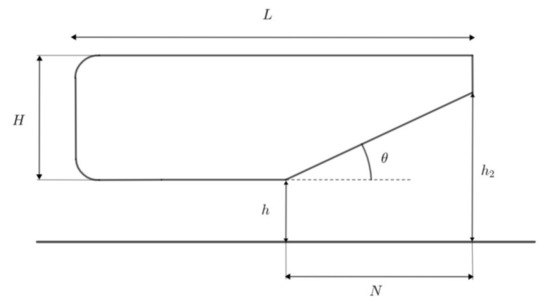
Figure 1.
Parameters of an Ahmed body with a ground-effect diffuser.
The pressure recovery in the diffuser is improved by the section shape and the endplate fence to produce as uniform distribution as possible in the vehicle longitudinal direction, avoiding local separation [9]. Consequently, the objective of the study is to investigate the effects of the diffuser geometry on the Ahmed body with vertical airfoil endplates in order to improve the understanding of flow behavior. The progress of vehicle aerodynamics, as a combination of the test process in wind tunnels and computational fluid dynamics (CFD), has significantly evolved in recent years in both road and motorsports cars [10]. CFD deserves special attention for its rapid advance in terms of simulation capability, accuracy, predictability, and software availability, and has allowed researchers around the world that cannot afford wind tunnel facilitates to contribute towards field predicting, for instance, the uncertainty of the car set-up [11,12].
Hence, three-dimensional CFD simulations of the Ahmed body are performed to observe the behavior of the flow under different diffuser configurations. First, a non-diffuser Ahmed body configuration is studied to act as a reference configuration for comparison. Then, a 25° diffuser is added at the end of the body for the second configuration. Finally, the third configuration consists of the addition of two rear vertical airfoil endplates at the end of the 25° diffuser. The separation in the areas in which pressure is recovered (diffuser main performance) and the entry of the leading-edge separation vortices of the rear tires are factors that reduce the effective sectional area of the diffuser exit. Vertical airfoils amend this. Based on the study of the results of the first two configurations, the third configuration substantially improves diffuser performance, being the most important contribution of this academic work. The CFD software used is OpenFOAM [13] as it is a free open-source software option available to provide numerical solutions to the desired geometry.
2. Literature Review
Passenger cars are being provided with different external aerodynamic devices (inverted wing, fins, side spoilers, etc.) to create disturbances in the flow field to improve drivability [14,15]. More recent works study the aerodynamic characteristics of tailing vehicles by using commercial CFD software and particle image velocimetry experimental technique [16] and aerodynamic noise prediction [17]. Race cars are always are provided with aerodynamic devices, the diffuser being the most important element to enhance the ratio downforce vs. drag.
2.1. Diffuser Performance
Downforce is the force of lift acting downwards generated on the car. In motorsport cars, the generation of downforce is extreme as it enables the car to reach very high speeds while taking corners on a track. This forces the four wheels onto the track asphalt enhancing the ground grip, thus allowing the car to travel faster. Creating downforce usually costs (induced) drag, so the amount of downforce needed depends on the track which is being driven on: tracks with more corners will benefit from high downforce to take these corners with a higher speed without slipping, while on tracks with few corners and longer straights downforce is needed but in a lower proportion [18].
2.1.1. Downforce Generation Mechanisms
Cooper et al. [19] observed three fluid-mechanical mechanisms appear when studying diffuser flow behavior. These are responsible for the generation of downforce on diffusers.
Considering a symmetric Ahmed body—without a diffuser—located far from the ground in free air, no lift is generated on the body as there is no pressure difference from the upper and lower surfaces, as airflow has the same velocity over both surfaces. When approaching the body to ground proximity, airflow beneath the body suffers an increase in its acceleration due to ground constraint, i.e., non-slip condition. This phenomenon is called ground interaction. The amount of airflow enters the underbody through a smaller inlet area compared to when located in free air. This decrease in the inlet area, as defined in the Venturi effect, asserts that the same amount of airflow that in free air entered the bottom surface, now has to flow through a smaller area, thus increasing its velocity to flow through this surface in the same time as it did in free air where the inlet area was larger. Due to the increase in flow acceleration beneath the body, this airflow becomes more asymmetrical around the body as on the upper surface the airflow has a certain velocity and on the lower surface it has higher velocity. Lift generation happens when a body suffers a pressure differential between its upper and lower surfaces, as seen in the wing’s airflow behavior. Therefore, as Bernoulli’s principle states, this flow acceleration implies a reduction of the underbody static pressure which generates downforce. The smaller the static pressure on the lower surface, the greater the downforce generated as the pressure difference between the upper (atmospheric pressure) and lower surface will be greater.
Closer to the ground, airflow acceleration beneath the body increases due to ground constraint reducing the underbody static pressure further, thus generating greater downforce [20]. Nevertheless, the increase in downforce with ride height decrease is limited due to fluid viscosity. These viscous effects are not dominant at larger ride heights, and for this reason downforce is maximum at a certain low ride height. However, if lowered further, underbody flow resistance increases due to the viscous effects limiting maximum downforce. See in Figure 2 how the coefficient of lift (CL) stops increasing when ride height is close to 0. If lowered enough, flow viscous effects from the boundary layer on the lower surface become more significant, leading to blockage area, a blocked-area fraction of an internal flow. This phenomenon occurs due to a non-uniform velocity profile across the inlet which becomes increasingly distorted as the flow experiences a positive pressure gradient. Viscous effects cause an increase of blockage area due to the increase of wall boundary layers with velocity profiles occupying the largest fraction of flow cross-section. This distorted velocity profile surely blocks part of the flow cross-section, which reduces the area ratio of the diffuser. The velocity profile non-uniformity is also accentuated by an inviscid mechanism. Under stationary, incompressible-inviscid flow, change in static pressure and velocity along an incompressible flow stream tube is defined by Equation (1).
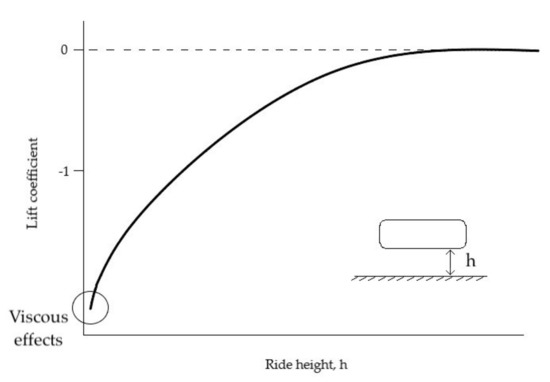
Figure 2.
Variation of lift coefficient with ride height.
In the case of a diffuser, change in static pressure is positive > 0 and velocity reduces < 0. This velocity reduction is highest when the local velocity is the smallest, which makes velocity differences across the diffuser more significant and the velocity profile gets highly distorted, leading to blockage. This results in a decrease of the pressure rise, thus reducing the downforce generated. Consequently, it is a phenomenon to bear in mind since it excessively reduces diffuser performance and effectiveness.
Even though a body with a flat underbody can generate downforce in ground proximity, the presence of an underbody upsweep zone at the rear of a symmetrical body (see Figure 3) creates a cambered shape, resulting in a significant increase of downforce even for large ride heights. The main objective of this mechanism is obtaining a flow asymmetry on the body, as seen for ground interaction but can be obtained at larger ride heights. A suction peak appears at the inlet of the diffuser, as shown in Figure 3, to prevent flow separation on the ramp of the diffuser [21]. An additional advantage of this mechanism is its effectiveness in reducing drag far from the ground. Furthermore, the upsweep of the diffuser reorientates the counter-rotating streamwise vortex pair upward, generated by the pressure difference between the diffuser and the region outside its longitudinal sides [22].
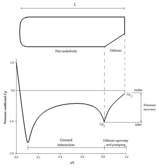
Figure 3.
Downforce mechanisms in
plot of an Ahmed body with diffuser.
The mechanism of diffusive pumping occurs due to the increasing cross-sectional area in the flow direction, which makes a decrease in the flow velocity over the diffuser length from inlet to outlet with its corresponding increase in static pressure (until reaching base pressure). The relaxation process consisting of delivering the airflow from the underbody to atmospheric conditions as smooth as possible (see diffuser part on Figure 3) requires an outlet to expand it. Provided flow stays attached, the bigger this outlet area, the smoother the airflow delivered to the base pressure. However, as the body is closer to the ground, the outlet cross-sectional area is reduced [23]. Thereby, there is a clear trade-off of ground interaction and underbody upsweep mechanisms which depends on the ride height. An additional drag component is also generated by this augmented flow and at small ride heights it can totally cancel the underbody upsweep advantage of reducing drag [24].
In summary, it is important to understand these three mechanisms and how they affect each other in order to determine the optimum diffuser geometry. First, ground interaction and diffuser pumping provide an increasing amount of downforce, while the upsweep angle reduces the drag considerably. Low ride heights are advantageous for downforce generation in ground interaction and diffuser pumping, which cancels the reduction of drag of the underbody upsweep. For this reason, it is stated that there is an obvious downforce/drag trade-off which depends on the ride height of the diffuser (see Table 1). Consequently, the ride height must be consciously chosen depending on the necessities: if drag reduction is important, larger ride heights will be implemented and if downforce generation is more significant, then smaller ride heights will be used considering the drag penalty.

Table 1.
Advantages and disadvantages of each downforce mechanism. Where (++) means it is highly positive, (+) it affects positively and (−) it affects negatively.
2.1.2. Flow Regimes
On the other hand, Zhang et al. [25] show the plot of the downforce coefficient - against the ride height divided into four different regions characterizing the downforce behavior of a ground-effect diffuser. In Figure 4, these four regions are clearly defined.
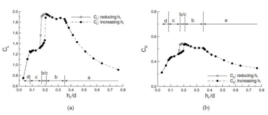
Figure 4.
Regions in (a) downforce and (b) drag coefficients plots with hysteresis (Reprinted from ref. [25]).
- 1.
- Force enhancement (a). As can be seen in Figure 4, in the first region (a), downforce increases with decreasing ride height (hr/d). A symmetric pair of counter-rotating vortices with a high axial-speed core and high levels of vorticity are present in the diffuser at this region, as shown in Figure 5.
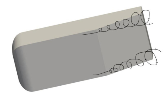 Figure 5. Pair of vortices formed on the underbody (Reprinted with permission from ref. [26]. 2017 RACE TECH).
 - 2.
- Force plateau (b). If ride height is decreased, downforce stabilizes on the upper limit of the plot in a linear approximation. The diffuser flow remains symmetric. However, the vortices significantly increase in size and the vortex core has low axial speeds (see Figure 6b). In this region, ride height reaches a critical value.
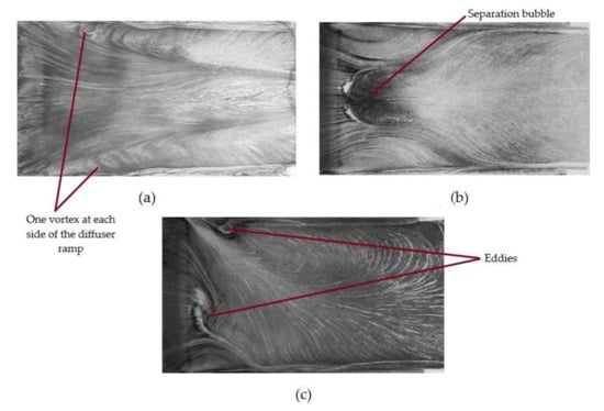 Figure 6. Flow behavior in the regions of (a) force enhancement, (b) force plateau and (c) force reduction (Reprinted with permission from ref. [26]. 2017 RACE TECH).
 - 3.
- Force reduction (c). In this stage, with further ride height reduction downforce considerably decreases. The symmetric vortex flow within the diffuser breaks down and results in a separated asymmetric flow through the diffuser as shown in Figure 6c.
- 4.
- Loss of downforce (d). As the name states, if ride height is decreased reaching extremely small values, near 0 mm, the generation of downforce is almost stopped. What happens is that the flow within the diffuser is totally blocked due to viscous effects for being so close to ground proximity, and hence significant airflow cannot go through. As defined for a ground interaction mechanism, the phenomenon of blockage area occurs. This results in a separated asymmetric flow appearance.
2.1.3. Effects of Diffuser Length
From Equation (2), the parameter N/L makes (1 − N/L) and N/L determines which pressure coefficient, or , is a greater contributor to the lower surface mean effective pressure coefficient.
where N and L are the length of the diffuser and the body (as shown in Figure 1), and the subscripts f and d denote the flat-underbody surface and the diffuser length, respectively. For small values of N/L the flat component is more negative than the diffuser’s because (1−N/L) is greater than N/L. The flat component becomes more negative by the following expression,
However, the parameter that multiplies it (1 − N/L) makes its contribution to decrease. The diffuser component’s weight will be due to the increase in N/L as the diffuser length increases. At a certain diffuser length, reaches a maximum and then decreases with further increase of the diffuser’s length, and the opposing effects in the flat component continue. In the paper [19], from a value of N/L = 0.31, increases, being less negative, which implies a drawback for downforce generation. Moreover, becomes more negative considering Equation (3), which makes become more negative, even for larger values of diffuser length past the maximum, and hence increasing downforce. However, if N/L is further increased, becomes less negative, making increase, reducing downforce.
2.1.4. Effects of Ride Height
The ride height is defined as the distance from the flat underbody to the ground. As the diffuser ride height is gradually lowered, the flow behavior within the diffuser changes from attached to separated and this influences the aerodynamic performance of the diffuser. How ride height influences downforce generation is clearly observed in the plot of Figure 4a where four differentiated regions are determined. For the force enhancement region, as ride height is lowered downforce increases significantly. Then if further ride height reduction, it reaches a critical value with maximum downforce acting on the body. In intermediate region b–c, between force plateau (region b) and force reduction (region c), aerodynamic hysteresis occurs. If greater ride height reduction is applied below this critical value, regions c and d take action with a substantial downforce reduction. As the ride height of the diffuser was reduced toward its maximum-downforce height, downforce enhancement was accompanied by increasing suction at the diffuser inlet, enhancement of streamwise flow velocity, and low pressure along the lengthwise sides of the diffuser due to the strengthening of the longitudinal vortices [22].
Fluid viscosity is a minimal concern for larger ride heights, but it becomes a dominating factor when ride height is reduced due to the restricted area underneath the body. At very low ride heights, the flow rate under the body is reduced since the underbody cross-sectional area is choked due to viscous forces dominant on the boundary layer. Thus, downforce generation is also restricted [23].
2.1.5. Effects of Diffuser Slant Angle
The diffuser slant angle θ is the angle between the flat underbody and the line that creates the diffuser (see Figure 1), and it affects the effectiveness of the diffuser. If it is too steep, it will cause a separation of flow under the car, increase the effect of turbulence, and increase drag. Otherwise, if it is too shallow, it will reduce the ability of the diffuser to create a low-pressure zone at the bottom of the Formula 1 car. However, the diffuser angle also has a great influence on the downforce generation of the car [18].
If the angle of the diffuser is close to zero the boundary layer flow will not detach, but the air speed will not be reduced enough to make a laminar transition of the air at the end of the car when to two airstreams meet. If the diffuser has a very large angle, the boundary layer flow will detach and the airflow underneath the diffuser will be turbulent. So, the angle of the diffuser is limited: when the angle is too small or too large, the diffuser will create more drag then necessary [21].
2.1.6. Effects of Vortex
The circular movement of fluid within vortices contains a lot of energy, which, if it was an ideal fluid, could be dissipated and the vortex would never disappear. When these vortices appear, they roll up under the diffuser, taking high energy air from the outside of the body and introducing it into the diffuser. However, they also take high energy air from below the level of the body and mix it into the body of airflow under the diffuser (see Figure 5). This phenomenon enables the diffuser to function at high angles without detaching and losing effectiveness [26].
The presence of a trailing counter-rotating vortex pair in the diffuser induces some level of upwash. Consequently, by Newton’s 3rd Law of action-reaction, the downforce acting on the diffuser body is the result of the force reacting to the diffuser flow being redirected upwards by the trailing vortex pair [27]. Zhang et al. [25] predict that the circulation of this counter-rotating vortex pair is directly related to the downforce produced.
where is the vorticity and S the surface. Regarding Equation (4), in order to increase the circulation when ride height is decreased—S is decreased—, the vortex size (vorticity) must grow at a faster rate such that their product continues increasing to maintain the circulation. When considering a vortex in a diffuser, its size is limited by the diffuser dimensions that decrease with ride height.
In the force enhancement region, far from the ground, two vortices roll up, one on one side of the underbody and the other on the other side as shown in Figure 5. Both these vortices originate on the corners of the diffuser inlet and expand as they move downstream on the diffuser ramp, moving inboard. Throughout this region, the flow is symmetrical and is attached on the diffuser ramp (Figure 6a) and if ride height is decreased, downforce increases (see Figure 4a). As the ride height is lowered, the main vortices move further to the interior of the diffuser and their size increases. A highly concentrated vortex core implies stable vortex flow. If ride height is lowered further, a separation bubble appears in the diffuser ramp which provokes a sudden increase of the vortex size after separation (but loses strength), hence downforce continues to increase. This happens in the force plateau region b, as can be seen in Figure 4a, where downforce decreases a little but suddenly suffers an increase, reaching its peak at a critical value of ride height. Below this, the downforce starts decreasing. In this phase, flow is still symmetrical, but it is a bit disturbed as shown in Figure 6b.
The force reduction region begins when ride height is further decreased below this critical value. From Figure 6c, the vortices in this phase are clearly asymmetrical with one main vortex dominating the flow behavior at the diffuser ramp. This occurs because one of the two vortices bursts (the vortex that bursts may be random), resulting in one main vortex. This provokes a great reduction in downforce, as can be seen in region b–c of Figure 4a. The rest of the flow enters in a weak re-circulating region with an axial flow reversal due to flow separation at the diffuser inlet. Consequently, a loss of suction occurs, confirming the vortex breakdown. In this region, once the vortex has burst, to improve the situation of the flow, the ride height must be higher than the ride height at which the vortex burst so as to obtain the symmetrical flow that there was before. As burst and re-creation happen at different heights, this leads to what it is called aerodynamic hysteresis. This is why the plot of downforce and drag in Figure 4 presents two lines between the force plateau and force reduction regions, with one for increasing and another for decreasing ride height. Additional ride height reduction implies smaller energy and worsening attachment of the flow, resulting in virtually complete separation from the diffuser surface.
3. Materials and Methods
3.1. Geometry
Three-dimensional CFD simulations are performed on an inversed Ahmed body geometry in order to observe the flow behavior under different diffuser configurations. This geometry is used as it is easier and faster to obtain reasonable results compared to a Formula 1 car geometry in which the computational time and resources are considerably greater. The standardized model of the Ahmed body is not used in this study, but the model shown in Figure 7 with the corresponding dimensions from [28] in order to verify the results obtained. The first case study is an Ahmed body without a diffuser, hence with a slant angle of 0°. Then, this case will be compared with the configuration shown in Figure 8b which incorporates a diffuser with slant angle of 25° in its bottom rear part, with a diffuser length of 182 mm (35% of the total body length). The comparison between these two cases is interesting since it will be observed how the addition of a diffuser substantially improves the generation of downforce compared to the same body that did not incorporate one.
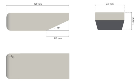
Figure 7.
Dimensions of the 25° diffuser Ahmed body geometry used.

Figure 8.
The three geometries of the Ahmed body simulated (a) 0° diffuser, (b) 25° diffuser and (c) rear airfoils 25° diffuser.
The last geometry simulated is presented in Figure 8c. It consists of an Ahmed body with a diffuser of 35% length and slant angle of 25°, as with the configuration presented previously, but two airfoils are added at each side of the rear part of the diffuser. The aim of the addition of the airfoils was to create a zone of low pressure (suction) at the back of the trailing edge of the body. For this reason, there is no reference of results for this geometry. Nevertheless, principally, an increase in the downforce coefficient should be observed.
3.2. Model and Solver
The simulations were performed with OpenFOAM which solves the Navier–Stokes and the continuity equations presented in Equations (5) and (6), respectively.
where denotes velocity, gravity, density, pressure, and kinematic viscosity. As external flows are difficult to approximate because it is hard to evaluate the flow downstream taking into account anything that could have affected the turbulence, the k−ωSST (shear stress transport) RAS turbulence model is used. It consists of a two-equation model to approximate the turbulence of the flow [29,30].
The turbulence kinetic energy k and the turbulence specific dissipation rate ω are obtained with Equation (7) [31].
where is the free-stream velocity, I the turbulence intensity, and / the eddy viscosity ratio with µ being the dynamic viscosity and µt the turbulent dynamic viscosity. One way of approximating the parameter ω is by approximating the turbulence length scale. Nevertheless, for external flows, this parameter is not easy to estimate. For this reason, there is another good technique to approximate the turbulence specific dissipation rate, which is by the eddy viscosity ratio /,the ratio between turbulent viscosity and molecular viscosity. According to research in different articles, websites, and references [30], this ratio is estimated to a value of 10, as it is shown to be a good approximation for the type of simulation considering its Reynolds number and the low turbulence. The initial value for the turbulence kinetic energy results in 0.06 m2/s2 and the turbulence specific dissipation rate with a value of 400 s−1.
Regarding the solver used, almost all articles researched that performed CFD simulations used the steady-state solver with SIMPLE algorithm. However, in this project, the variation with time of the diffuser flow behavior is used. For this reason, the transient solver pimpleFoam will be used to principally observe the development of the vortex generated. To ease convergence, first the command potentialFoam is run in order to initialize the velocity field solving for potential velocity. Then, the simpleFoam is run to obtain the steady-state solution to later initialize the transient solver pimpleFoam. The pimpleFoam is corrected with 3 nCorrectors, 3 nOuterCorrectors, and 1 nNonOrthogonalCorrectors. With the use of these correctors, at each time step, the number of total iterations can be reduced.
3.3. Domain and Mesh
The mesh is made with blockMesh and snappyHexMesh. As shown in Figure 9, the dimensions of fluid volume surrounding the body are 8 L × 2 L × 2 L—as indicated in [32], leaving only a distance between the ground and the geometry for the ride height selected of 20 mm.
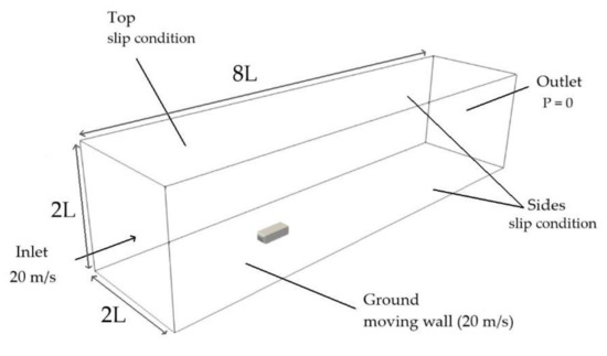
Figure 9.
Computational domain with boundary conditions.
The side view of the mesh is presented in Figure 10. It is clearly seen how refinement regions created surround the body concentrating the cells around it. The smaller refinement region, called refinement wake, concentrates the major part of the cells around the geometry, giving special treatment to those critical zones of the body.
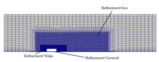
Figure 10.
Side view of the mesh of the Ahmed body with 0° diffuser configuration.
The average value of the dimensionless wall distance y+ is around 7 for the three meshes the maximum value is 15 (see Figure 11). For values y+ > 5, the implementation of wall functions is helpful for convergence purposes and to reduce the stiffness of the turbulence equations, as opposed to a near wall treatment, which generally adopts y+ < 1 when solving for low Reynolds (Re) number [33,34]. Wall functions for k, , and are used. These wall functions are used because of the very small cell requirements in certain areas of the mesh where the boundary layer is dominant, hence it would be necessary to apply a finer application of the values of these parameters to obtain a more accurate solution. They are used when the computational resources are limited, and the grid mesh cannot be as refined as needed to obtain a wall distance y+ 1 near the wall. Wall functions kqRWallFunction, omegaWallFunction, and nutkWallFunction are applied for the parameters k, and , respectively, on the wall surfaces, where the boundary layer is important to study the flow behaviour better.
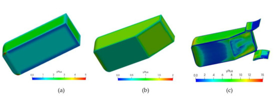
Figure 11.
y+ value the (a) 0° diffuser, (b) 25° diffuser and (c) 25° diffuser with rear airfoils configurations.
In order to verify the suitability of these meshes (Figure 10 and Figure 12), a convergence study is performed by Richardson extrapolation and calculation of the grid convergence index (GCI) [35,36]. The three meshes considered for each case with their corresponding parameters are presented in Table 2.
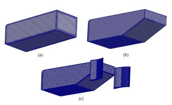
Figure 12.
Mesh of the (a) 0° diffuser, (b) 25° diffuser and (c) 25° diffuser with rear airfoils configurations.

Table 2.
Mesh parameters for each geometry configuration.
and are the relative errors between the medium and fine meshes and the medium coarse and medium grids. The parameter R is the convergence ratio used to check whether the solutions are in the asymptotic range of convergence, and it is defined as follows:
where is the grid refinement ratio (ratio between the medium and fine grids) and the order of convergence [35]. The convergence ratio for the cases shows values closer to 1, which indicates that the solutions are within the asymptotic range of convergence. This indicates that the grid is sufficiently refined such that it is considered that adequate results will be obtained.
3.4. Boundary Conditions
The boundary conditions for each wall of the mesh are represented in Figure 9.
- Inlet velocity set at 20 m/s. A velocity of 20 m/s may seem small for a Formula 1 car, but as explained before, diffusers are added to create downforce to improve the cornering speed. When cornering, velocities do not reach very high velocities, but small velocities. For this reason, in the simulations, this velocity of 20 m/s is set as the initial velocity.
- Pressure outlet set at atmospheric pressure.
- Ground velocity set at 20 m/s.
- Slip condition on the side walls and the top of the fluid domain.
3.5. Simulation Setup
OpenFOAM was used to run the simulations. The following simulation conditions are imposed in the case study:
- Free-stream velocity: = 20 m/s (72 km/h). Knight et al. [28] used this velocity on their simulations as it is the velocity used in the wind tunnel tests too. It is supposed that the wind tunnel cannot acquire very high velocities.
- Newtonian fluid: = 1.5 · 10−5 m2/s
- Turbulence model: k−ωSST. Between both RANS turbulence models k− and k−ωSST, it is concluded that the k−ωSST turbulence model is more accurate than the k−, which usually gives worse results on external aerodynamics cases [28].
- Turbulence intensity I: 1%. This parameter is defined by the ratio between the turbulent velocity fluctuations and the mean velocity. As a common trend, the free-stream will be taken with low turbulence intensity external aerodynamic of a value of 1%, as in [37,38]. This value is a reasonable measure of current wind tunnels.
As the variation with time of the diffuser flow behavior is desired, the transient solver pimpleFoam is used to principally observe the development of the vortex generated. For a better convergence of the results, potentialFoam and simpleFoam are run beforehand, thus helping reduce the simulation time.
3.6. Simulation Performance
Both the simulations and the post-processing were realized with a laptop presenting the following specifications: a processor Intel Core i7 (8th Gen), 16Gb of RAM, and 1 TB SSD. Hence, neither supercomputer nor a cluster is used to perform all the simulations. For this reason, the number of cells of the meshes cannot be very high due to the lack of computational resources.
In Figure 13, the stability of the forces of each simulation are presented. All force coefficients tend to stabilize, although the vertical airfoils case shows a more fluctuating trend of stabilization, which may suggest flow instabilities.

Figure 13.
Stability of the forces of the (a) 0° diffuser, (b) 25° diffuser and (c) 25° diffuser with rear airfoils configurations.
4. Results and Discussion
The simulations performed with a ride height of 20 mm show the velocity and pressure distributions depicted in Figure 14 and Figure 15, respectively. The downforce and drag coefficient results are presented in Table 3.
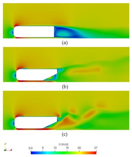
Figure 14.
Velocity distribution on the XY-plane of (a) 0°, (b) 25° and (c) vertical airfoils 25° diffuser configurations.

Figure 15.
Pressure distribution on the YZ-plane of (a) 0°, (b) 25° and (c) vertical airfoils 25° diffuser configurations.

Table 3.
Results obtained for each simulation.
The simulation of the non-diffuser configuration intends to act as a base geometry to compare with for following simulations. With no diffuser, the body itself produces downforce due to ground effect when it is located close to the floor. If this case was placed further from the ground, the generation of downforce would be even smaller because the flow would be symmetric, and as shown in previous sections, a symmetrical body in free stream does not generate lift. The non-diffuser configuration velocity distribution is depicted in Figure 14a. It is observed that the largest velocities are concentrated at the bottom of the body where the flow is directed towards the exit of the underbody. As there is no diffuser that smooths the transition of the flow from underneath the body to the free-stream, an abrupt change in velocity between the flow underneath the body and the velocity of the flow appears at the rear of the body. Under the body, the flow shows a red colour meaning top velocity of 27 m/s, while the wake that appears at the back of the body shows very small velocities between 0–5 m/s [39]. This phenomenon is what limits downforce. The downforce obtained is 0.182, a rather small value considering the Formula 1 downforce requirements. Two vortices appear at the rear bottom of this body (see Figure 16). In this case both vortices are quite small, which justifies the small value of downforce obtained. The vortices are somehow constrained by the end of the body as they do not have the space to be developed. For this reason, a 25° diffuser is added to the non-diffuser geometry in order to observe how the presence of a diffuser improves the downforce on the body under the same conditions. In addition, Figure 15a,b show the gain in pressure distribution from non-diffuser to 25° diffuser geometry.
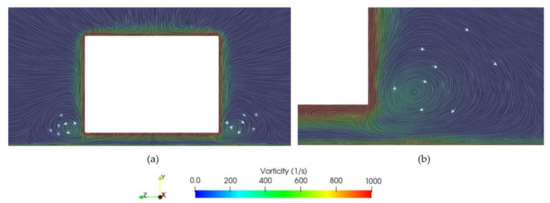
Figure 16.
Vorticity on the YZ-plane for (a) 0° diffuser and (b) zoomed view of right vortex.
The presence of the 25° diffuser, as presented in Figure 17 and Figure 18, shows an improvement in the performance of the body when generating downforce. The downforce obtained is of 1.419, approximately eight times more downforce than in the non-diffuser configuration. The transition of the flow from larger velocities of 20–26 m/s to the free-stream is clearly smoother than in the case of the non-diffuser geometry. Figure 14b shows a smooth transition of the flow velocity leaving from the diffuser inlet to the outlet. This higher velocity at the underbody, as for the Venturi effect, will imply a reduction in the pressure on this region, which enhances the generation of downforce on the body. The wake produced at the back of the body is more significant than the one observed for the previous case due to the smoother transition and upwash created by the presence of the diffuser, as well as its higher drag. In this case, as shown in Figure 17, two vortices generate at the diffuser inlet with much bigger size and energy than the ones generated on the 0° diffuser. The two symmetrical counter-rotating vortices verify the theory that stated these vortices appeared on the diffuser [40]. The theory also stated that the larger the size of the vortex, the larger the downforce. That is clearly seen when comparing both 0° and 25° diffuser cases: the 0° diffuser vortices were small and concentrated at the bottom of the body with a vorticity of approximately 400 s−1, whereas in the 25° diffuser the vortices are much bigger in size, almost 3 times the height of the body, and with a much higher vorticity of 1000 s−1. These vortices redirect the flow upwards on the underbody (see the three configurations in Figure 19) and according to Newton’s 3rd law, this motion upwards is the cause of the generation of downforce acting downwards on the body. For this reason, as in this case, the vortices generated are larger, their vorticity is larger, thus increasing the vertical load acting downwards on the body.
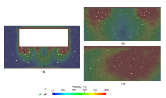
Figure 17.
Vorticity on the YZ-plane for (a) 25° diffuser and zoomed views of (b) centre of the diffuser and (c) right vortex.
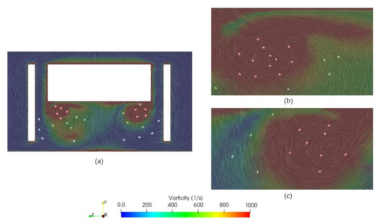
Figure 18.
Vorticity on the YZ-plane for (a) vertical airfoils 25° diffuser and zoomed views of (b) left and (c) right vortices.
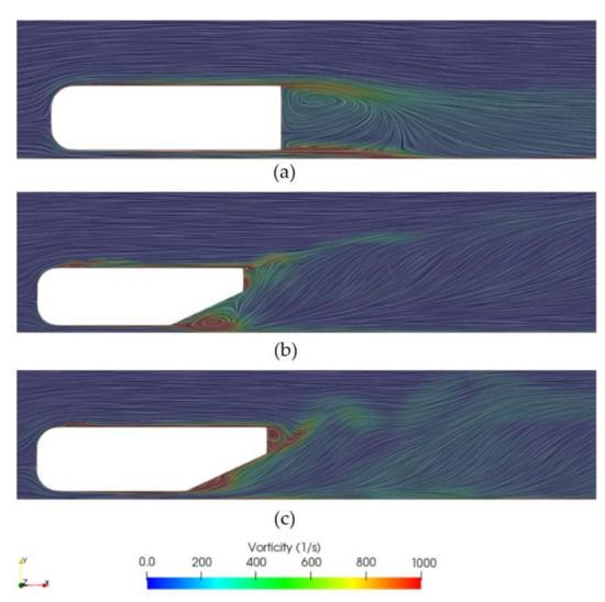
Figure 19.
Vorticity on the XY-plane for (a) 0°, (b) 25° and (c) vertical airfoils 25° diffuser configurations.
Finally, the velocity distribution around the vertical airfoils 25° diffuser configuration is shown in Figure 14c. The aim of studying this case is to observe that a low-pressure zone appears at the back of the body, which increases the downforce produced [15]. This case shows a more distorted transition of the flow velocity leaving diffuser. This is due to the more accentuated vortex generated by the vertical airfoils. Figure 15c shows a counterbalance effect of the vertical airfoils by helping to reduce the pressure at the exit, an effect that will help to increase the in-flow rate in the diffuser.
The downforce coefficient obtained is of 2.14, which has substantially increased over 51% with respect to the case of the 25° diffuser without airfoils (as well as the drag). As in previous cases, two vortices appear, one at each side of the diffuser. The left vortex rotates in the counterclockwise direction, while the right one rotates in the opposite (clockwise) direction. In Figure 20 and Figure 21, the origin of these vortices can be observed. They originate at each side of the diffuser inlet, creating the large vortices depicted in Figure 18, where it is shown that the left vortex is larger in size than the right one due to unsteady flow behavior. The flow inside the diffuser is dominated by strong longitudinal vortices (see the three configurations in Figure 19). When the rear ride height evolves, these vortices become weak or disintegrate, the diffuser is no longer able to hold the flow, and a stall could occur [2]. Hence, the vertical airfoils create a lower pressure area at the back of the body, as shown in the Figure 15c. Kinematic pressure decays to a value of −300 m2/s2, while in the case without airfoils (Figure 15b) the minimum pressure was −150 m2/s2. This phenomenon increases the mass flow rate entering the diffuser (thus, larger downforce produced). In Figure 22, the pressure coefficient distribution shows how at the diffuser inlet the pressure decays up to a = −1.5. Then, along the diffuser distance, the pressure recovers, reaching the atmospheric pressure at the exit of the diffuser, hence obtaining a pressure recovery of 1.5.

Figure 20.
Flow visualization on the vertical airfoils 25° diffuser surface for (a) initial and (b) final simulation states.
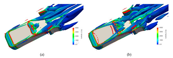
Figure 21.
Flow visualization vorticity on the vertical airfoils 25° diffuser surface for (a) initial and (b) final simulation states.
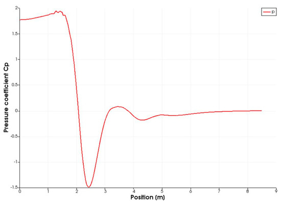
Figure 22.
Pressure coefficient distribution of the vertical airfoils 25° diffuser configuration.
In conclusion, the addition of two vertical airfoils at the back of the body signifies an improvement in the generation of downforce [41]. Hence, adding aerodynamic elements that create a low-pressure zone at the back of a car is a good technique in order to increase the downforce. Otherwise, it must be noted that the drag coefficient is quite high, so it should be considered in order to apply this diffuser configuration or to introduce a device that reduces the drag produced.
5. Conclusions
The academic work presented here has discussed how motorsport diffusers work and their importance to the performance of the car. The main objective was to understand how flow behaves through these diffusers and how it increases the downforce acting on the vehicle, with a range of diffuser geometries suitable for road and race car applications. The study comprises the downforce increment modifying the diffuser geometry. Furthermore, three CFD simulations are performed on three different geometries. The geometry considered is the Ahmed body, which is a standard model used to represent the flow in motorsport studies.
Three diffuser configurations at a ride height of 20 mm are simulated: without a diffuser (slant angle of 0°), with a 25° diffuser, and with a 25° diffuser with the addition of two vertical airfoils, one at each side of the diffuser. The three simulations performed reasonable results. From least to most downforce generated, the non-diffuser configuration results in the least downforce generation configuration compared to the two other cases, followed by the 25°, and finally the largest downforce is produced by adding the rear airfoils to the 25° diffuser configuration. It must be highlighted that, with the increase in lift coefficient, the drag increases consequently. The case of the non-diffuser Ahmed body shows the least downforce generation ( = 0.18), as theory predicted. For the 25° diffuser configuration, the downforce increases substantially with respect to the non-diffuser configuration up to obtaining a lift coefficient of approximately −1.42, eight times more than the 0° diffuser. Last but not least, the simulation of the case of the 25° diffuser Ahmed body with the addition of two rear vertical airfoils is performed in order to create a suction zone at the back of the Ahmed body with the aim of increasing the downforce. Effectively, the downforce obtained for this last case was significantly greater than the second case with just the 25° diffuser. The resulting lift coefficient was −2.14, i.e., 51% more downforce with the addition of the airfoils. The region of low pressure at the back of the body could be clearly observed.
Now that a comparison between the conventional Ahmed body and a new promising configuration has been made as a baseline, new configurations can be designed and evaluated to further improve the performance of diffusers. As further work, the full simulation of a Formula 1 car with different diffuser configurations could be performed. An adapted configuration with the addition of rear airfoils and varying types of airfoil used could be simulated in order to find the optimum configuration that provides the highest performance.
Author Contributions
L.P. conceived the article. Methodology, numerical simulation, analysis, L.P.; writing—original draft preparation, L.P.; original contributions and review, W.T.; supervision—review and editing, P.J.G.-M. All authors have read and agreed to the published version of the manuscript.
Funding
This research received no external funding.
Institutional Review Board Statement
Not applicable.
Informed Consent Statement
Not applicable.
Data Availability Statement
The data presented in this study are available on request from the corresponding author. The data are not publicly available due to privacy reasons.
Conflicts of Interest
The authors declare no conflict of interest.
Abbreviations
The following abbreviations are used in this manuscript:
| A | Cross-sectional area [m2] |
| AR | Aspect ratio |
| CFD | Computational Fluid Dynamics |
| Drag coefficient | |
| Lift coefficient | |
| Diffuser surface mean-effective pressure coefficient | |
| Flat-underbody surface mean-effective pressure coefficient | |
| Lower surface mean-effective pressure coefficient | |
| GCI | Grid Convergence Index |
| h | Ride height [m] |
| H | Ahmed body height [m] |
| h/H | Non-dimensional ride height |
| I | Turbulence intensity |
| L | Ahmed body length [m] |
| N | Diffuser length [m] |
| N/L | Non-dimensional diffuser length |
| p | Pressure [Pa] |
| pc | Order of convergence |
| r21 | Grid refinement ratio |
| R | Convergence ratio |
| RANS | Reynolds Average Navier Stokes |
| S | Reference surface [m2] |
| SST | Shear Stress Transport |
| Free-stream velocity [m/s] | |
| Velocity [m/s] | |
| Velocity [m/s] | |
| W | Ahmed body length [m] |
| Circulation [m2/s] | |
| Relative error | |
| Diffuser slant angle [°] | |
| Molecular dynamic viscosity [kg/(ms) | |
| Kinematic viscosity [m2/s] | |
| Density [kg/m3] | |
| Vorticity [1/s] |
References
- Formula 1 Dictionary. Downforce vs Drag. Available online: http://www.formula1-dictionary.net/downforce.html (accessed on 3 May 2020).
- Nakagawa, M.; Hojo, T. Typical vortical structures around Formula 1 car. In Proceedings of the 6th International Conference on Vortex Flows and Vortex Models, Nagoya, Japan, 17–20 November 2014. [Google Scholar]
- Katz, J. Race car aerodynamics: Designing for speed, 1st ed.; Bentley Publishers: Cambridge, MA, USA, 1995; pp. 1–270. [Google Scholar]
- Tingwall, E. The physics of diffusers: How to make a car really suck. Car Driv. Available online: https://www.caranddriver.com/features/a15112568/the-physics-of-diffusers-how-to-make-a-car-really-suck-feature/ (accessed on 2 March 2020).
- Taiming, H.; Xiaodong, Z.; Zhongmin, W.; Zhengqi, G. Experimental and numerical investigations of the vehicle aerodynamic drag with single-channel rear diffuser. Proc. IMechE D J. Automob. Eng. 2020, 234, 2216–2227. [Google Scholar] [CrossRef]
- Soso, M.D.; Wilson, P.A. Aerodynamics of a wing in ground effect in generic racing car wake flows. Proc. IMechE Part D J. Automob. Eng. 2006, 220, 1–13. [Google Scholar] [CrossRef]
- Jowsey, L.; Passmore, M. Experimental study of multiple-channel automotive underbody diffusers. Proc. IMechE Part D J. Automob. Eng. 2010, 224, 865–879. [Google Scholar] [CrossRef] [Green Version]
- Ahmed, S.; Ramm, G.; Faltin, G. Some salient features of the time-averaged ground vehicle wake. SAE Tech. Pap. Ser. 1984, 840300. [Google Scholar] [CrossRef]
- Ogawa, A.; Mashio, S.; Nakamura, S.; Masumitsu, Y.; Minagawa, M.; Nakai, Y. Aerodynamics analysis of formula one vehicles. Development methodologies for formula one aerodynamics, 2009. Honda RD Tech. Rev. 2009, F1, 142–151. [Google Scholar]
- Senft, V.; Gillan, M.A. Recent advances and test processes in automotive and motorsports aerodynamic development. Proc. Inst. Mech. Eng. Part C J. Mech. Eng. Sci. 2019, 233, 7573–7589. [Google Scholar] [CrossRef]
- Bradford, J.; Montomoli, F.; D’Ammaro, A. Uncertainty quantification and race car aerodynamics. Proc. Inst. Mech. Eng. Part D J. Automob. Eng. 2014, 228, 403–411. [Google Scholar] [CrossRef] [Green Version]
- Ahlfeld, R.; Ciampoli, F.; Pietropaoli, M.; Pepper, N.; Montomoli, F. Data-driven uncertainty quantification for Formula 1: Diffuser, wing tip and front wing variations. Proc. Inst. Mech. Eng. Part D J. Automob. Eng. 2019, 233, 1495–1506. [Google Scholar] [CrossRef]
- Open FOAM Foundation. Open FOAM Resources. Available online: https://openfoam.org/resources/ (accessed on 15 April 2020).
- Kumar, A.; Sebben, S.; Sällström, E.; Jacobson, B.J.H.; Broniewicz, A. Analysis of subjective qualitative judgement of passenger vehicle high speed drivability due to aerodynamics. Energies 2019, 12, 2839. [Google Scholar] [CrossRef] [Green Version]
- Kurec, K.; Piechna, J. Influence of side spoilers on the aerodynamic properties of a sports car. Energies 2019, 12, 4697. [Google Scholar] [CrossRef] [Green Version]
- Li, Q.; Dai, W.; Yang, Z.; Jia, Q. Investigation on aerodynamic characteristics of tailing vehicle hood in a two-vehicle platoon. Proc. IMechE Part D J. Automob. Eng. 2020, 234, 283–299. [Google Scholar] [CrossRef]
- Zhong, L.; Li, Q.; Wang, Y.; Yang, Z. Aerodynamic noise prediction of passenger vehicle with hybrid detached eddy simulation/acoustic perturbation equation method. Proc. IMechE D J. Automob. Eng. 2019, 233, 2390–2404. [Google Scholar] [CrossRef]
- Mansor, A.; Radzi, M.; Harun, Z. F1 in SCHOOLS competition to promote STEM: Aerodynamic investigation of miniature F1 in SCHOOLS car. In Proceedings of the 1st International STEAM Education Conference, Kuala Lumpur, Malaysia, 13–16 November 2017; pp. 708–712. [Google Scholar]
- Cooper, K.R.; Bertényi, T.; Dutil, G.; Syms, J.; Sovran, G. The aerodynamic performance of automotive underbody diffusers. SAE Tech. Pap. Ser. 1998, 980030. [Google Scholar] [CrossRef]
- Diffusers. RaceCar Engineering. Available online: https://www.racecar-engineering.com/tech-explained/diffusers-engineering-basics-aerodynamics/#:~:text=With%20this%20in%20mind%2C%20the,the%20car%20to%20corner%20faster (accessed on 10 March 2020).
- Khokhar, A.A.S.; Shirolkar, S.S. Design and analysis of undertray diffuser for a formula style racecar. Int. J. Res. Eng. Techn. 2015, 11. [Google Scholar] [CrossRef]
- Ehirim, O.H.; Knowles, K.; Saddington, A.J. A review of ground-effect diffuser aerodynamics. J. Fluids Eng. Trans. ASME 2019, 141, 20801. [Google Scholar] [CrossRef]
- Peddie, K.M.; Gonzalez, L.F. CFD Study on the Diffuser of a Formula 3 Racecar. Technical Reports 1. Orbit Univ. of Sydney Undergrad. Res. J. 2009, 1, 18–35. Available online: https://openjournals.library.sydney.edu.au/index.php/Orbit/article/view/193/0 (accessed on 20 April 2020).
- Ehirim, O.H.; Knowles, K.; Saddington, A.J.; Finnis, M.V. Aerodynamics of a convex bump on a ground-effect diffuser. J. Fluids Eng. Trans. ASME 2018, 140, 91102. [Google Scholar] [CrossRef] [Green Version]
- Zhang, X.; Senior, A.; Ruhrmann, A. Vortices behind a bluff body with an upswept aft section in ground effect. Int. J. Heat Fluid Flow 2004, 25, 1–9. [Google Scholar] [CrossRef]
- Toet, W. How Do Motorsport Diffusers Work? RaceCar Eng. 2017, 8. Available online: http://www.racetechmag.com/2017/08/willem-toet-explains-motorsport-diffusers/ (accessed on 25 April 2020).
- Mayoral, S.; Weiss, H.; Edirisinghe, R. On the relationship between the vortices from an underbody diffuser in ground-effect and the resulting downforce. SAE Tech. Pap. Ser. 2019. [Google Scholar] [CrossRef]
- Knight, J.; Spicak, M.; Kuzenko, A.; Haritos, G.; Ren, G. Investigation of vehicle ride height and diffuser ramp angle on downforce and efficiency. Proc. Inst. Mech. Eng. J. Automob. Eng. 2019, 233, 2139–2145. [Google Scholar] [CrossRef]
- Open FOAM: User Guide. k-Omega Shear Stress Transport (SST). Available online: https://www.openfoam.com/documentation/guides/latest/doc/guide-turbulence-ras-k-omega-sst.html (accessed on 10 May 2020).
- Wilcox, D.C. Turbulence Modeling for CFD, 2nd ed.; DCW Industries, Inc.: Anaheim, CA, USA, 2002. [Google Scholar]
- Murad, J. Defining Turbulent Boundary Conditions. Available online: https://www.simscale.com/forum/t/defining-turbulent-boundary-conditions/80895 (accessed on 14 March 2020).
- Flow over Ahmed Body using Ansys FLUENT. Available online: https://skill-lync.com/projects/ahmed-body-challenge-70 (accessed on 10 April 2020).
- Blazek, J. Computational Fluid Dynamics: Principles and Applications; Elsevier: Oxford, UK, 2005. [Google Scholar]
- Moukalled, F.; Mangani, L.; Darwish, M. The Finite Volume Method in Computational Fluid Dynamics; Springer: Berlin/Heidelberg, Germany, 2016; Volume 6. [Google Scholar]
- Roache, P.J. Perspective: A Method for Uniform Reporting of Grid Refinement Studies. J. Fluids Eng. 1994, 116, 405–413. [Google Scholar] [CrossRef]
- NASA. Examining Spatial (Grid) Convergence. Available online: https://www.grc.nasa.gov/www/wind/valid/tutorial/spatconv.html (accessed on 10 April 2020).
- CFD-Wiki. Turbulence intensity—CFD-Wiki, the free CFD reference. Available online: https://www.cfd-online.com/Wiki/Turbulence_intensity (accessed on 25 April 2020).
- Maric´, T.; Höpken, J.; Mooney, K.G. The OpenFOAM® Technology Primer. Sourceflux 2014. [Google Scholar] [CrossRef]
- Guerrero, A.; Castilla, R. Aerodynamic study of the wake effects on a formula 1 car. Energies 2020, 13, 5183. [Google Scholar] [CrossRef]
- Jermann, C.; Pujals, G.; Meliga, P.; Serre, E.; Gallaire, F. Characterization of the streamwise vortices and near-wake dynamics in the turbulent flow around the 25◦ Ahmed body based on SPIV. In Proceedings of the 3rd GDR Symposium “Flow Separation Control”, Ecole Centrale de Lille, Lille, France, 7–8 November 2013. [Google Scholar]
- Wieser, D.; Nayeri, C.N.; Paschereit, C.O. Wake structures and surface patterns of the DrivAer notchback car model under side wind conditions. Energies 2020, 13, 320. [Google Scholar] [CrossRef] [Green Version]
Publisher’s Note: MDPI stays neutral with regard to jurisdictional claims in published maps and institutional affiliations. |
© 2021 by the authors. Licensee MDPI, Basel, Switzerland. This article is an open access article distributed under the terms and conditions of the Creative Commons Attribution (CC BY) license (https://creativecommons.org/licenses/by/4.0/).