Abstract
The figure of Leonardo da Vinci has been extensively studied. In fact, the Leonardiana Library brings together tens of thousands of titles on Leonardo and his work. During the second half of the 20th century, various treaties were published focusing on Leonardo’s activity as an engineer, and more recently, an increasing number of scientific articles that focus on certain aspects of the prolific work of the genius such as construction, mechanics, strength of materials, etc. have been published. This article analyses the main contributions of the Tuscan genius in the field of design focusing on his processes for generating new solutions, his developments regarding graphic representation techniques, his improvements in plotting and measuring instruments, and how some of his devices were implemented and continue to maintain their usefulness.
1. Introduction
Leonardo (Vinci 1452–Amboise 1519), although better known as an artist and painter, was a multidisciplinary genius capable of standing out in most areas of knowledge; engineering, architecture, zoology, medicine, botany, etc. Even music did not escape his voracious interest in dominating everything known.
In the field of product engineering, he was capable of designing or projecting ships with armoured hulls and moved by paddles, movable bridges, bronze sculptures over 7 m high, diving suits and submarines, bicycles, self-propelled vehicles predecessors of the automobile, musical instruments, etc., even humanoid automatons. In the architecture and civil engineering field, he designed fortresses and defences for cities, sanitation channels, diversions of rivers, and even projected an “ideal city”.
Only a few of those designs or projects were actually executed back then, so some of his contemporaries did not take several of his works seriously. For this reason, a large number of them stayed in what we now call the Conceptual Design phase, others reached Preliminary Design, while only a few reached the Detailed Design phase, using the usual nomenclature in the technical systems design literature [1].
Today, the bridge that Leonardo designed conceptually in 1502 for the Ottoman Sultan Beyazid II in the Golden Horn (Istanbul) is a similar reality in the city of Aas (Norway). The 7.30 m tall Sforcesco Horse, which he designed in detail, can be seen in the square of the Milan racecourse (“Il Cavallo”), and in the city of Grand Rapids, Michigan (“American Horse”). His detailed design of the Paddle Boat was copied and materialised in the 18th century by Engineer Robert Fulton on his steamboats. For all this, Leonardo should be considered a visionary designer ahead of his time.
This article aims to answer the following questions. What did Leonardo contribute to the design methods and tools of his time beyond the achievements represented in his works? Or being more specific, what were the sources of inspiration for the generation of new solutions to the objects designed by Leonardo, to what extent did his designs rely on pre-existing knowledge, and how did he use experimentation to improve them? What improvements did it make in terms of the way of representing these objects and in the drawing and measurement tools he developed?
2. Materials and Methods
Leonardo was and is known as one of the best painters of all time, although as a result of the rediscovery and study in detail of his great manuscript production, which comprises 23 notebooks, most of them in the 19th century (Codex Atlanticus, Arundel Codex, Leicester Codex, French manuscripts A-M-12 volumes-, Forster Codex-3 volumes-, Codex of the “Flight of Birds” or the Turin Codex, Codex Trivulziano and Windsor Royal Collection Manuscripts) and others in the middle of the 20th century (Madrid Codices I and II) [2,3,4,5,6], has gained fame in other disciplines such as engineering, urban planning, anatomy, botany, or even as a scientist and inventor.
As a result of the studies published by the French art historian and curator of the Louvre museum, Charles Ravaisson-Mollien (1848–1919), “Les Manuscrites de Léonard de Vinci” (1881–1891) [7], a new interest has arisen in the scientific-technical work of Leonardo. Since then, countless scientists and science historians have studied many of the different aspects of Leonardo’s scientific-technical work [8,9].
According to the researcher in physics at the University of California at Berkeley Fritjof Capra (Vienna, 1939) “Good designers are capable of systematic thinking and synthesis. They excel in visualising things, in organising known elements into new configurations, in creating new relationships; and they are able to transmit these mental processes in the form of drawings almost as quickly as they occur. Leonardo, of course, had all these capabilities to a very high degree. Furthermore, he had a mysterious natural talent for perceiving and solving technical problems—another key characteristic of a good designer—to the point that, in his case, it was almost second nature” [10].
3. Leonardo Designer
3.1. Design, Engineering and Engineering Design
According to Braha and Maimon, “Design as problem-solving is a natural and the most ubiquitous of human activities” [11]. Design begins with the acknowledgment of needs and dissatisfaction with the current state of affairs, and realization that some action must take place in order to solve the problem.
USA’s Accreditation Board for Engineering and Technology (ABET) defines Engineering Design “as a process of devising a system, component, or process to meet desired needs and specifications within constraints. It is an iterative, creative, decision-making process in which the basic sciences, mathematics, and engineering sciences are applied to convert resources into solutions. Engineering sciences are based on mathematics and basic sciences but require further knowledge to apply the creativity needed to solve engineering problems. These studies provide a bridge between mathematics and basic sciences on the one hand and engineering practice on the other” [12].
Under these premises, there is no doubt that Leonardo was, among other things, a prolific and multifaceted designer, both in the fields of engineering and architecture and in industrial design [9,13]. Although modest, he was also very conscious of being special, and it is not by accident that the general public remembers him and not the names of his contemporaries [14].
As stated by Blessing [15], design is a complex activity, involving artefacts, people, tools, processes, organisations and the micro- and macro-economic environment (market, legislation, society) in which it takes place. According to Nigel Cross [16], “any identifiable way of working, within the context of designing, can be considered to be a design method. Design methods can, therefore, be any procedures, techniques, aids or ‘tools’ for designing”.
From these definitions, it is interesting to highlight the importance of methods, devices, instruments, and tools for designing artefacts, since these concepts will be used frequently in this work. To ensure proper use of terminology relating to technical methods and design tools, the following definitions are attached, selected from the different options provided by the Oxford Dictionary and the Merrian-Webster Dictionary. An artifact is usually a simple object showing human workmanship or modification as distinguished from a natural object. A device is a piece of equipment or a mechanism designed to serve a special purpose or perform a special function. A technique is a way of carrying out a particular task, especially the execution or performance of an artistic work or a scientific procedure. A tool is a device or implement, especially one held in the hand, used to carry out a particular function. An instrument is a tool or device used for a particular task, especially for specialist or scientific work.
3.2. Design Approaches in Leonardo. From Nature Observation to Analogies
In technical systems projects (equipment, machines, artefacts, etc.), because they are considered complex, the parts cannot be designed individually without taking into account the influence of other parts in their surroundings; that is, they are systemic. Therefore, it is necessary to observe the relationship of each of the parts with the whole, that is, the overall objective to be achieved (target system), as well as the relationship between them. Hence the convenience, when studying the object, to consider its division into subsystems and components, taking advantage of areas with less interference. That is, they must be studied at the same time with an interdisciplinary vision, at least in the initial stages.
Leonardo was not only able to create complex systems such as clocks, mechanisms, and machines, but also by taking advantage of the knowledge gained in all these fields, and in that of human physiognomy (acquired as a young man in the workshop of the Florentine sculptor and painter Andrea Verrocchio) and forensic anatomy (carried out with Marcantonio della Torre, professor of anatomy at the University of Pavia), he relates them all and observes them from a global and interdependence perspective. Thus, he identifies the human body as a complex system (he considers that this is how Nature works) and is able to extrapolate this metabolic and organic knowledge to his designs. He even projects and operates a humanoid automaton.
Thus, his work constitutes a clear precursor of current design strategies, starting from the consideration of its object as a global and interdependent system. And also, of the principles of sustainable or ecological design, aware of the influences on the climate, the landscape, the living beings and the whole of Nature. In relation to this, he writes: “An invention will be never found, more beautiful, simpler, or more economical than those of nature, since nothing is lacking in its inventions and nothing is superfluous”; “The world is ruled, not by God, but by the incessant creativity of nature” [17]. Leonardo admired and mastered geometry, but for him the complexity of nature could not be reduced to figures and mechanical analysis. His special attention to qualities, dynamism, and overall view is an essential part of his science, present today in current systemic approaches and in the complexity theory [18].
Martin Kemp, professor of Art History at Oxford University and one of the highest authorities alive on Leonardo’s science and art, considers that Leonardo is the father of Topology. He also emphasizes that “analogy” is the main technique used by Leonardo to explain the behaviour of things. Nature displays its functions and human ingenuity must imitate them, but all things designed (devices, elements, machines) must follow the “Necessity Principle” as Nature does, where all designed forms perform some function: although wood exists, “Nature has not created bows to shoot arrows” [19].
The use of analogies was also a technique used by Leonardo in many of his projects. In the manuscripts of Figure 1, he analyses the movement of a human arm under stress, draws it, and generates an artificial mechanism that emulates it. A clear analogy is given between Nature, which was its main source of inspiration, and the projected machine. This mechanism is supposed to have been used in the construction of his “Automata” project.
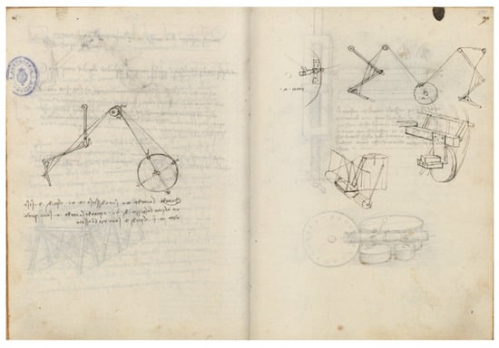
Figure 1.
Study of mechanisms for the arm of an automaton. Madrid Codex I, f. 90 v, 91 r. National Library of Spain [4]. Note: f. is the abbreviation for sheet (foglio); r is the abbreviation of front (recto) and v is short for reverse (verso).
He also made analogies for his devices with which he intended to make man fly, assimilating the wings of his prototypes to those of his detailed “Studies on the flight of birds” existing in the Codex of Turin, as well as of bats.
3.3. Leonardo’s Design Principles from the Point of View of Current Design Theories
In the evolution of design theories in the last 50 years, it is possible to highlight the influence of the Systems Theory, the scientific method, and the use of analogies, as well as other projective methods and techniques. The next section includes the analysis of the way in which Leonardo already applied the scientific method and the systemic approach in his work, while considering environmental factors, introducing ecological and ergonomic principles.
According to the Technical Systems Theory [20], objects, artefacts or products are seen as technical systems that transform energy, material, and information. The functional behaviour of a technical system is fully determined by physical principles and can be described by physical laws. The engineering design problem is to find and define the geometry and materials of the system in such a way that the required prescribed physical behaviour is realised in the most effective and efficient way.
Taking this approach, the conclusion that the form (of the artefact) is created to fulfill a function, that is, the function creates the organ, can also be derived from the statement of the principle of necessity observed in nature by Leonardo. This approach can be observed in the current engineering design proposals. For example, the Standard VDI 2221 [21] structures the design process in 7 steps, generating the Function Structure in the second stage, while the Module structure is generated in the fourth. The Theory of Technical Systems proposes a design process in 5 steps (Purpose, Process Model, Function Model, Organ Model and Component Model) [22]. Suh’s Axiomatic Design [23,24] sees designing as a mapping process from the “functional space” into the “physical space”, or, more specifically: mapping a given set of functional requirements (FRs, “what we want to achieve”) into a defined set of design parameters (DPs, description of “how we want to achieve it”) [20].
According to Professor Plinio Innocenci, “sometimes Leonardo seems to approach the modern concept of design. However, we must not make the mistake of using a contemporary point of view to define an artist-engineer who lived 500 years ago. Leonardo is still the son of his time, and he is not the only one to use technical design, and perhaps he is not even the best. Some projects by Francesco di Giorgio or Bonaccorso Ghiberti reach a level of technical precision that rivals that of Leonardo. However, his machine repertoire represents something unique and, in this sense, extremely original for the variety of solutions and innovations” [25].
He obviously was not the only engineer of his time, but he was the best and exceeded by far the achievements of his contemporaries and predecessors. For example, he improved Roberto Valturio’s (1405–1475, Rimini) and Francesco di Giorgio Martini’s (1439–1501, Siena) machine designs and the hydraulic contraptions of Mariano di Iacopo’s (1382–1453, Siena), known as “Il Taccola”. He also complemented and surpassed Brunelleschi’s crane designs for his project for the diversion of the Arno River. In fact, in his technical designs more than 500 years ago, he already included most of the documents which make up a Project. According to Sara Taglialagamba, [26], the definition “Leonardo industrial designer” was first introduced by Carlo Pedretti in his book Leonardo Architetto [27].
3.4. Leonardo and the Scientific Method
The influence of Leonardo da Vinci’s work in the history of science is of fundamental importance [28,29]. Although he obviously learned from his predecessors, his contributions to scientific development have not been established until recently.
In the architectural field, Filippo Brunelleschi (1377–1446) and his disciple Leon Alberti (1404–1472) influenced his work. In the mechanical field, it has been established that he read Ponderibus’s Tratactus and the Treatise on Weights by Biagio Pelacani, also known as Blasius de Parma (1365–1416). He was also influenced by the school of Giordano de Nemore and by Albert of Saxony (1320–1390), to whom we owe a theory of weight which influenced the development of mechanics by solving many difficulties of Aristotelian physics.
His friend, the mathematician, philosopher and professor at the University of Pavia, Facio Cardano (1444–1524), gave him access to the treatise “Perspectiva Communis” by the theologian, professor at the University of Oxford and archbishop, Jhon Peckham (1220/1225–1290), while in optics and mathematics he studied the texts of the Polish friar, theologian, and mathematician Witelo (Erazm Ciolek) (1230–1280/1290) and of the Arab physicist, astronomer, and mathematician Alhacen (Ibn Al-Haitam) (965–1040) [30,31].
The scientific method is based on observing a phenomenon, developing hypotheses, and carrying out the corresponding experiments to confirm or discard said hypothesis. If the experiments confirm the hypotheses, the link of certainty (law) is established, and if they do not confirm it, it returns to the beginning. Leonardo, as its precursor, did it in a similar way, opting in his investigations for the experimental or investigatory system of Aristotelian roots. Thus, he writes: “Mathematics gives us the supreme certainty”; “No human investigation can be called true science if it does not go through mathematical proof” or “no certainty exists where any of the mathematical sciences or those connected with them cannot be applied” [32].
Or also [17]: “Before proceeding with an investigation, I will do some experiment, because my intention is to invoke the experience first and then demonstrate, with reasoning, why such experience must operate in such a way.”
“And this is the true rule according to which observers of natural effects must proceed. As much as nature begins with reason and ends in experience, we must follow the opposite course, that is, begin, as I said before, with experience, and with it investigate the reason.”
“Experience is never wrong, only your judgements are wrong, promising strange results to personal experimentation” [28].
Thus, for example, he was concerned with the strength of beams and made mathematical formulations about their bending strength. He managed to define laws, although imperfect, regarding beams’ elastic line for different sections (for square, horizontal and end-supported beams), coming to observe that the strength varies in relation to the square of its length.
Unlike most of those who later came to be at the forefront of the construction of the scientific method (Galileo, Descartes, Newton, and Leibniz), Leonardo da Vinci was not a mathematician. He took mathematics classes with Luca Pacioli [29]; however, his relationship with mathematics was mainly based on geometry, due to his great interest in studying the laws of linear perspective. Leonardo would use abstraction by replacing time with a succession of drawings, each representing a certain instant.
Soledad Álvarez, Professor of Art History at the University of Oviedo stated that “The multifaceted and masterful creative activity of Leonardo is the origin of the scientific illustration in which image outweighs theoretical reflection in thoroughness and accuracy” [33].
3.5. The Scientific Method in Action: Tests and Experiments
For his projects and designs, Leonardo needed to know the efforts that both the material meant to be used and the human resources employed could make. For this reason, he carries out his own studies on strength of materials and human nature. Thus, he studies the buckling behaviour in beams as loads are applied at their centre. He also does it with ropes and cables when they are subjected to stresses, both directly and through pulleys [34]. He also studies friction between different bodies and on rolling elements on different surfaces. All this to establish possible transferable estimates after each of his projects.
The Madrid Codices I and II (Figure 2) are respectively entitled “Treatise on Static and Mechanics” and “Treatise on Fortification, Static and Geometry” [35]. Among Manuscripts at the French Institute in Paris, Manuscript “E” is a treatise on physics and mechanics, and Manuscript “M” is one on geometry. In the London Forster Codex, there are themes of geometry, hydraulics, and physics. Finally, the Codex Atlanticus (Ambrosian Library of Milan) also has pages with topics of mechanics, physics, and mathematics.
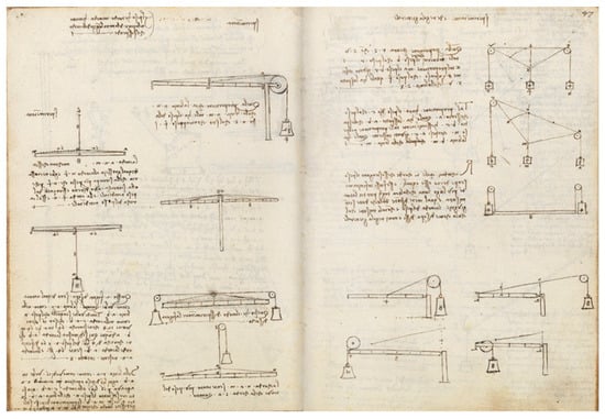
Figure 2.
Study of weights. Madrid Codex I, ff. 76 v, 77 r. National Library of Spain [4].
Although his studies in mechanics have some errors, he is also recognised for some contributions to the science and strength of materials, such as being the first one to draw the catenary and propose its study using a discrete model still in use today [36].
4. Contributions to Graphic Representation Techniques for Design
In the words of the writers and historians Luca Antoccia and Carlo Pedretti, “Leonardo can boast of having had an indisputable primacy, which places him at the head of the beginnings of modern scientific illustration. Indeed, no one before him had been able to expose a complex technical project so effectively in a drawing” [37].
How, 500 years ago, did Leonardo da Vinci manage to carry out such high-quality technical designs and to formulate his conceptual models solely through drawing? Leonardo took advantage of his great knowledge in drawing and painting, together with his spectacular creative capacity, to generate an important contribution of graphic techniques that can be used in technical designs.
This section will discuss three of the main contributions to graphical representation techniques developed by Leonardo da Vinci, explosion diagrams, charts of route families, path diagrams, and bird’s eye maps.
4.1. Explosion or Exploded Diagrams
This object representation technique has been very useful for understanding the conformation and operation of machines and products. But it was not until the middle of the 20th century that the term emerged as a three-dimensional (isometric) illustration that shows the coupling relationship of parts, subsets, and large assemblies. It can also show the assembly or disassembly sequence of the detailed parts. It is still widely used today to capture joint interior views of drawings of mechanisms, mechanical or electrical elements, etc. Three-dimensional views and animation are the new heirs of this technique.
Leonardo, who dissected both human bodies (in his facet as an anatomist), and machines and artefacts (in his engineering facet) into individual parts, needed to represent them through separate parts, but without losing sight of the whole. For this purpose, he used this technique, together with the identification and description of the parts through letters and short texts close to the views, which is why he can be considered the precursor of the use of explosion diagrams for anatomical studies and, together with the Italian engineer Mariano di Jacopo “Il Taccola”, for machines and artefacts.
As an example, in the Codex Atlanticus, f. 30 v at the Ambrosian Library of Milan, he draws his assembled machine (argano) in perspective (Figure 3), and to its right he decomposes it in detail, also in a perspective view, as if it had “exploded” but so that although the mechanisms are already separate, they retain their overall vision. Thus, it does not require any explanation for its construction or to understand its operation.
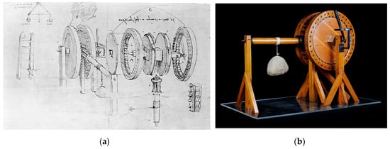
Figure 3.
(a) Reciprocating machine for weight lifting (Argano), Codex Atlanticus f. 30 v, (1478–1480) [38]; (b) Model at the Museum of Science and Technology of Milan [39].
It is a machine for lifting weights composed of a mechanism for alternating movement from a crank, produced by a human being, which is converted to a continuous movement so that it lifts a weight steadily. The machine invented by Leonardo has as its main drive a mechanism that today would be called mechanical hammers.
4.2. Diagrams or Charts of Route Families
He is also a pioneer in making use of what are now called route family graphics, valid to represent a parameter or a variable that varies only depending on another single variable.
Leonardo estimated that the increase or decrease in force or natural “potenze” follows a pyramidal law; that is, an arithmetic proportion (he extended his Pyramidal Law of Optics to stresses, which he assimilated to the inclined plane or wedge-shaped triangle, as well as to pressure in his hydraulic studies). He stated that force increases with speed and decreases with distance, while weight and percussion increase proportionally with speed. For him, his Pyramidal Law represented a universal constant.
In his studies of screw fasteners, to justify their development, he also assimilates them to an inclined plane, and he explains its relationship with helical development in an existing diagram in the Madrid Codex I, f. 86 v at the National Library of Spain (Figure 4).
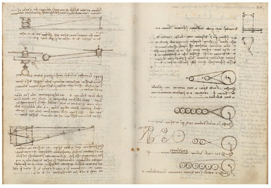
Figure 4.
Study of screw fastener development, Madrid Codex I, f. 86 v 87 r. National Library of Spain [4].
He also studies the phenomenon of pressure in different cases: in open watercourses, as in his design of the irrigation channel to San Cristofano, existing in the Codex Atlanticus f. 1097 r at the Ambrosiana Library of Milan (1509); in the reach of water jets, as can be seen in the detail of the Madrid Codex I, f. 134 v, at the National Library of Spain (Figure 5), where the “pyramidal” consideration of the phenomenon is observed again (the distance or reach of the jet decreases by increasing its height); or in closed pressure vessels, in his study of the reach of pressurised water in Manuscript C, c. 7 r, at the French Institute in Paris (France).
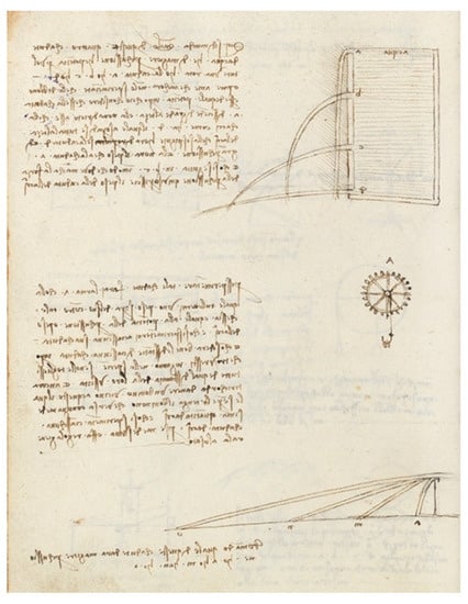
Figure 5.
Water reach detail, Codex Madrid I, f. 134 v, National Library of Spain [4].
Likewise, he can be considered a pioneer in the use of diagrams in a circular arrangement, using a simile of the string diagrams, in order to show functional relationships between different parts of the drawing, such as force lines. For example, Leonardo estimated that the force needed to overcome the inclined planes followed an arithmetic ratio, so in one of his traction studies, to calculate the necessary traction force in a bullock cart in relation to the diameter of the car wheels, he expresses the growth of the wheel using a concentric circular drawing and relates it to the lateral pyramid of the effort that the oxen must make (Codex Atlanticus f. 561 v, at the Ambrosiana Library of Milan). He also uses similar circular diagrams for his studies of mechanics and optics in the Arundel Codex, f. 93 r at the British Library in London, which records a ratio between a degree of momentum and its corresponding degree of percussion in Florentine units of measure.
4.3. Bird’s-Eye Maps
Leonardo is also the author of several plans and maps, especially of cities and land linked to Tuscany and, to a lesser extent, to the Papal States of that time. He developed them during his second Florentine period (1500–1506), at the beginning of which he served César Borgia (Rome 1475–Viana 1507), who appointed him architect and general engineer of the papal dominions. “We order and command that the bearer of this, our well-loved and very exalted architect and general engineer Leonardo da Vinci, who we have commissioned the inspection of the squares and fortresses of our states, be given the help required in each case or that in his judgement he deems necessary” [32]. At his service, he carried out studies of fortifications and cities and accompanied him in his military campaigns on Romagna.
During the government (Signorina) of the city of Florence, Leonardo was chosen to write the project for the diversion of the Arno river so that Florence would have direct access to the sea, without going through Pisa, its enemy city. The promoter of the idea had been Nicolas Machiavelli (Florence 1469–1527) in 1503, as secretary of the Florentine Chancellery. It was in this project that Leonardo acted the longest as a cartographer/topographer, producing magnificent plans and maps with detail and precision like no one else had ever achieved before. Most of them are found in the Royal Library of Windsor, in the Design and Prints Cabinet of the Uffizi Gallery in Florence, and in the Leonardo Museum, in Vinci.
He also studied and improved the perspective technique, so that together with his mastery of drawing and colour, he was able to generate views from the sky of the areas and highlight whatever he wanted at any time in an exceptional way (Figure 6). Until the “Quattroccento”, and even much later, slopes were represented as simple “molehills” (e.g., the Map of the “Trasimeno” Lake or “di Perugia” from 1600, by the Italian cartographer and mathematician Giovanni Antonio Magini (1555–1617), almost 100 years after Leonardo’s).
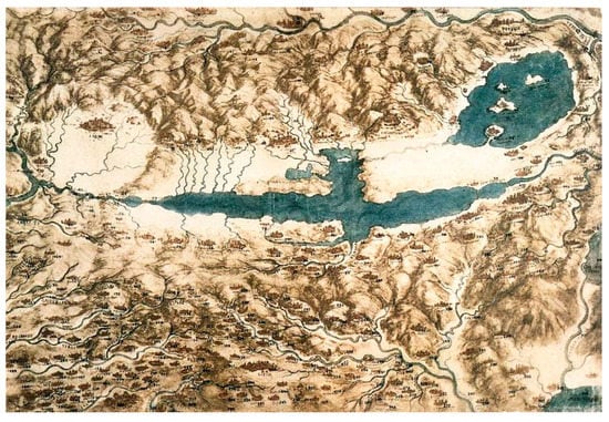
Figure 6.
Map of the Val di Chiana, Royal Collection, RLW 12278, (1502–1504). [40].
Leonardo overcomes all this and uses contour shading and his “chiaroscuro” technique to achieve greater objectivity in the representation of the territory. In addition, he used the distortion of scales technique in the appropriate areas to highlight what he considered necessary (watercourses, cities, mountains and valleys, etc.). The combination of all these techniques shows maps with an exceptional finish for those who see them, with an adequate sense of depth, size, or comparative distance in relation to the rest of the drawing, making Leonardo the precursor of “bird’s-eye view” plans and maps, when it was not possible to view places from the air.
4.4. Contribution of This Techniques to the Practice of Design
Plans, along with models and prototypes, are the most important form of communication in design practice. As seen in the three techniques presented, Leonardo takes advantage of his creative ingenuity, his mastery of drawing and painting, and his exceptionally advanced knowledge of geometry and perspective to innovate in the techniques of graphic representation with highly accurate diagrams, graphs, charts and plans, and impressive graphic quality.
In this regard, the Director of the Institute and Museum for the History of Science in Florence, Paolo Galluzi, states: “The objective pursued by Leonardo is to provide a precise and absolutely clear representation of the structure and operation of extremely complex mechanisms, using a series of graphic resources (plan and elevation views, transparency views, component views, simulation of kinematic chains, use of “chiaroscuro” to underline the surfaces in contact, schematization of the lines of force, etc.) that nobody before he had organically conceived and, above all, consciously applied to a communication project related to the horizon of technology” [33].
5. Contributions to Design Tools and Instruments
Project theorists emphasise the importance of the instruments and tools applicable to it, thus the so-called systemic ones such as Hubka and Eder in their “Theory of Technical Systems” [22] specify the need to be knowledgeable of the instruments that can be used to design, while the non-systemic ones such as Gómez-Senent classify the Operating Instruments as a fundamental dimension of the Project/Design [41].
Leonardo contributed innovations such as the improvement of the adjustable opening compass, the creation of a parabolic compass as the first generation of ellipsographs, the improvement of the prospectograph, his odometer, or his darkroom.
5.1. The Compasses
Since ancient times, the compass has been an important design instrument both for the generation of circumferences, as well as for obtaining the bisectors of angles, the drawing of perpendicular and parallel lines, the comparison between measurements, and even has been used in proportional calculation.
The Greeks already considered it as the most elegant and extremely simple construction tool, not only due to its application area is design, but also for mathematics, astronomy, navigation, topography, military use, etc. It has also been widely used as an indicative representation element of science and art.
A large number of special compasses were created in the Renaissance, with specific functions such as the generation of ellipses, parables, etc. Leonardo is no stranger to it; he designed various compass models both for conventional use with an adjustable opening, as well as other more complex ones suitable for drawing conical curves such as ellipses (the so-called ellipsograph), or parables (parabolic compass). He also designed moving centre reduction compasses and even created a compass for epicycloid curves.
As a true example of the Renaissance and as a humanist, he assimilated man as the centre of the universe, and as a great lover of nature, he studied its proportions and established their ideal, generating around 1492 his famous “Vitruvian Man” (in honor of the brilliant Roman architect) or of the “divine proportions” (existing in the Accademia Gallery, Venice). In his attached text he writes: “… if a man lies on his back, with his hands and feet extended, and places the end of a compass on his navel, the fingers and toes will touch the circumference of the circle that we thus draw” [42].
His compass models (Figure 7) are reflected in several of his codices and manuscripts, some with exceptional detail that would allow their construction and use.
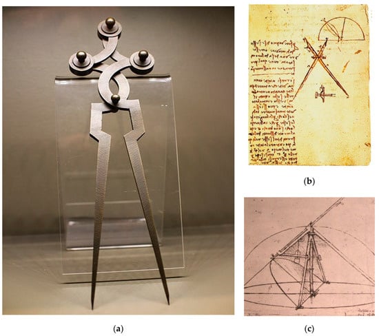
Figure 7.
(a) Reproduction of a compass designed by Leonardo, [43]; (b) proportional or reduction compass. Forster Codex I f. 45 (1485), [44]; (c) Parabolic Compass. Codex Atlanticus f. 1093 r, [45].
5.2. The Prospectograph
The Italian architect León Battista Alberti (1404–1472) already mentioned the use of this instrument in some of his works [46], but Leonardo is the first to draw it in detail in his Codex Atlanticus in f. 5 r (1480–1482) and describe its use. Even Leonardo himself is drawn using his veil prospectograph, drawing an armillary sphere (Figure 8).
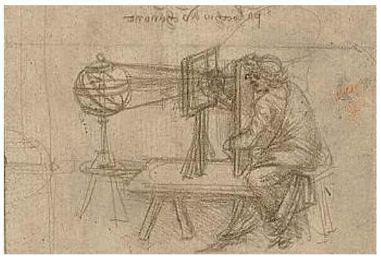
Figure 8.
Enlarged detail of the prospectograph being used by Leonardo. Codex Atlanticus f. 5 r [47].
Leonardo distinguishes and uses two kinds of prospectographs: the veiled and the glass one. For the one with a veil, already named by Alberti, the observed image is drawn directly with some staining element (e.g., bitumen) and is later transferred to paper. The other, the glass one, is based on the representation on glass of the external reality maintaining a fixed point of view; it is the one that uses a window full of grids (also known as Leonardo’s Window), where the designer observes the object through the scope of the prospectograph and transfers them to his paper, where there are also grids similar to those of the window (this model is the one that Albert Dürer (1471–1528) later popularised in Germany).
From the study and analysis of the drawings thus made, the principles governing the representation in a conical perspective were subsequently established.
5.3. Odometer and Pedometer
An odometer is a device that indicates the distance travelled by the person, or by the vehicle that has it incorporated (from the Greek “hodo” = road and “metron” = measurement). It is the precursor of the distance indicators and tachographs of today’s vehicles. Initially of mechanical constitution, today they are electronic.
The Greek mathematician, engineer, and astronomer Archimedes of Syracuse (287 BC–212 BC) is credited with the possible invention of this instrument. Later, the Roman architect and engineer Vitruvio (80≈70 BC–15 BC) mentions it again in his treatise “De Architectura”. It seems that its first use was made by the engineer and mathematician Herón de Alejandría (1st–75th century), by incorporating gears into the carriage wheels in order to know the distance travelled by them. However, it was not until the Renaissance that Leonardo described its construction and characteristics, being the first to draw it to detail.
Leonardo, in 1502 (first Roman stage), was commissioned by César Borgia (son of Pope Alexander VI) when he was named “architect and general engineer of the Papal dominions”, to establish defences and improvements in the fortifications of the Pope “Borgia” dominions. To do this, he needed to carry out large longitudinal measurements, for which he devised several automated length measurement machines. On folio 1b r (around 1504) of the Codex Atlanticus at the Ambrosian Library in Milan (Figure 9), two odometers and a pedometer are drawn in detail.
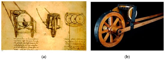
Figure 9.
(a) Study ot two odometers. Codex Atlanticus, f. 1b r, [48]; (b) Odometer model at the National Museum of Science and Technology of Milan [49].
The trolley-shaped odometer measured lengths with the units established at the time (“braccias”), while the pedometer measured it with the equivalence to “steps” of the person driving it.
In Leonardo’s Odometer, the cogwheel was “designed to advance one tooth every 10 bracces travelled (about 6 m), until, when reaching sixteen hundred meters (one mile), a pebble fell audibly into a metal container” [10]. For each turn of the large central wheel, one tooth of the lateral cogwheel was advanced vertically; once the total turn of the latter had been exhausted, another upper horizontal wheel was already activated, which had incorporated small balls or round stones in its upper part, and one of them was dropped into a box located in the lower part of the trolley. It was enough to count the number of balls that had fallen to know the length travelled.
5.4. Contribution of this Tools to the Practice of Design
Designers need tools that allow them to trace their plans and drawings with precision; they need tools to transfer to said plans the existing reality on which the designed object is going to be inserted; they need tools so that the designed object, the artifact, is brought to life, and built to the correct dimensions. Leonardo was not just satisfied with proposing innovative designs and leaving them at a conceptual level; he wanted to put them into practice, materialize them, and build them.
The tools that Leonardo refined contributed to improving the detailed design of the designed objects, as well as being the perfect complement to take advantage of the advances in graphic representation techniques shown in the previous section.
6. Discussion on the Functional Feasibility of His Designs
A large number of the devices, machines, and mechanisms designed by Leonardo Da Vinci, and represented in his nearly 7000 preserved manuscript folios, only reached the level of conceptual design. For this reason, Leonardo’s activities as an engineer have become particularly famous through a series of models whose construction began in Milan in the 1930s [33]. Although the accuracy of some of the reconstructions has since been questioned, and his famous war machines were perhaps the area where he was least innovative, his contribution lay not so much in the gadgets as in his new ways of drawing them and his methodical approach to their underlying principles.
It is also important to note that Leonardo’s designs of mechanisms and devices were based on in-depth study and experimentation on the statics of the rigid solid. He studied the deflection of bent beams subjected to different loads applied at different positions, trying to correlate stress and deformation, also dealing with compound stresses, in terms of normal stress or bending. In order to carry out these theoretical studies and characterise the strength of the materials, he designed machines to perform tensile tests (Codex Atlanticus f. 82 r) and also for repeated impact tests (Codex Atlanticus f. 21 r) [50].
On the other hand, most of Leonardo’s scientific-technical projects, due to the technological limitations of his time, never materialised, and none of them last to this day. For this reason, there is controversy over whether they could be put into practice with current instruments and materials, and, during the last decades, different researchers have tried to demonstrate the feasibility and benefits of his designs, some of which are analysed in this section.
Leonardo da Vinci carried out an enormous number of designs and projects, but to maintain coherence with the previous sections, when analysing examples of the functional feasibility of Leonardo’s designs, artifacts linked to the material execution of construction projects have been chosen; that is, tools that can be used in the works that Leonardo designed and/or carried out, such as the crank lift, the hammer for piling, and the mechanical jacks. The self-propelled vehicle has also been included due to the absolute originality of this design.
6.1. The Manual or Crank Lift
Leonardo designed important works that required large land movements and lifting loads, so he designed several machines and tools to facilitate these tasks. The Madrid Codex I, f. 9 r, at the National Library of Spain contains the design of a device suitable to act as a lift or manual elevator for loads (Figure 10). It works by means of a crank, which moves a worm screw that makes the gear rims and inner nuts turn, through which the “pull” rope or cable slides. As the lifting screw prevents the mechanism from turning in both directions, it allows for safe load raising or lowering. Furthermore, with proper multiplication, it allows movement with very little effort.
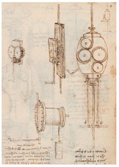
Figure 10.
Study for the mechanism of a manual lift (1495–1497), Madrid Codex I, f. 9 r, National Library of Spain [4,52].
As proof of his mastery in weightlifting, the Milanese painter and historian Giovanni Paolo Lomazzo (Milan 1538–1600) stated in 1590: “And he showed the art of lifting weights with ease [with his books], of which all of Europe is full and are held in high esteem among experts, because they consider that no more can be done than what he has already done” [51]. In fact, practically the same design continues to be used today in construction sites for lifting loads or even for people-carrying scaffolding in façade work.
6.2. The Hammer for Piling
Piling machines serve to insert precast wooden, concrete, or metal elements into the ground, in the form of a post or column. Its function is to prepare foundations in terrains that are unsuitable for building. Said elements, called “piles”, are usually “driven” into the ground by “hammer” blows, so that the element descends penetrating the ground until reaching the designed depth.
In the Codex Atlanticus, f. 785 (around 1500) (Figure 11), Leonardo draws his machine for driving logs into the terrain that he intended to use in his project to divert the Arno river in Florence. It consists of a device that lifted a weight in a guided way using pulleys and cranks so that it hit the log with the highest possible force. The crank pulley ratio enabled the repetition of the operation. The essence of this way of working has not changed to this day compared to Leonardo’s design, except for the power source used for weightlifting.
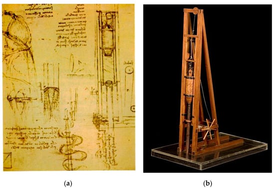
Figure 11.
(a) Study of a piling machine, Codex Atlanticus, f 785, Ambrosian Library of Milan [53]; (b) Model of Leonardo’s pile machine, at the National Museum of Science and Technology of Milan [54].
6.3. The Mechanical Jacks
Leonardo states in his Notebooks: “Mechanics is the paradise for mathematical sciences, because with it mathematics bear fruit”. A great connoisseur of physics, mechanics, metallurgy and the operating principles of machine elements, he uses this knowledge to develop several machine tools. Among them, he designs at least three different mechanical jacks.
The ratchet jack consists of holding a vertical fixed rack and makes the gear system rise or fall with the weight by turning a crank. The adequate reduction ratio between wheel and pinion will reduce the effort required to lift weights. Leonardo includes it in his Codex Atlanticus, f. 0998 r, at the Ambrosiana Library of Milan (Figure 12a). Both in electromechanical workshops and in jacks to change wheels in vehicles, this mechanism is still used today.
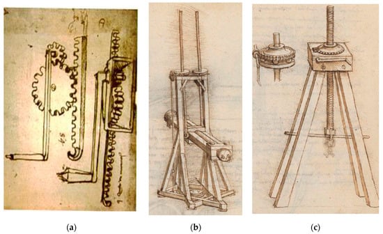
Figure 12.
(a) Detail of the Codex Atlanticus, f. 0998 r, Ambrosian Library of Milan, [55]; (b) detail of the Madrid Codex I, f. 34 r, National Library of Spain [4]; (c) detail of the Madrid Codex I, f. 26 r, National Library of Spain [4].
The spindle jack uses a screw-nut mechanism that allows the displacement of the former by making a rotating movement over it while keeping the nut fixed. In this way, a circular movement is transformed into a rectilinear one. It is simple and safe, but slow to operate, since with one turn of the screw it only moves forward the length of the thread pitch. In the Codex Atlanticus f. 0138 r, at the Ambrosiana Library of Milan, he describes the design of a mechanical jack for lifting or dragging cannons, as well as another similar device for fixed dragging of loads, both using the spindle system. This type of jack is still common in both the metal mechanic and construction sectors.
The screw jack with anti-friction bearing incorporates a kind of rotating toothed ball bearing, between the fixed support platform and the rotating upper toothed disc. In addition, it incorporates a lateral crank to facilitate rotation. Due to the presence of the ball bearing and a tooth sprocket on its upper part, the device works more easily and with less effort. It is included in the Madrid Codex I f. 34 r (Figure 12b) and f26 r (Figure 12c) at the National Library of Spain. This solution from Leonardo continues to be used today by tool manufacturing companies for mechanical workshops.
6.4. The First Self-Propelled Vehicle
Thoroughly knowledgeable about the elements of machines (his Madrid Codex I, entitled “Treatise on Static and Mechanics”, from 1493, can be considered the most complete treatise on Mechanics of the Renaissance), Leonardo designed the first self-propelled vehicle known in history. He takes advantage of the force on two previously loaded spiral winding springs, enclosed in drum-shaped compartments, which transfer their power to two wheels. In the Codex Atlanticus, f. 812 r (1478–1480) at the Ambrosiana Library of Milan (Figure 13), he establishes his project with two views: one plan view, representing springs, gears, crossbows, etc., and another in perspective, where he adds the idea of a possible steering system. Consisting of a small supplementary wheel coupled to its rear part and a stem accessible from above the vehicle, it would act as a steering wheel to be oriented at convenience, or through previous programming. For the latter, he used “eccentrics” in different ways, incorporated into the rotary axes. Depending on the shape of the “eccentrics” initially introduced, the direction of the vehicle will change. It also incorporates two adjustable front leaf springs that can act as a control for the gears that interconnect the power springs with the wheels to control the speed of the vehicle. Finally, it incorporates a wooden stem that acts as a general brake by remote control, acting on the teeth of the gears or horizontal wheels, preventing movement towards the rear vertical wheels, ensuring that power is not transmitted to the wheels even in the event that the springs are loaded. A ring acting on the stem and through a rope removed it from a distance, allowing the vehicle to move. In the lower part of the manuscript, the supplementary part that acted as an initial brake operated from a distance by means of a rope is represented.
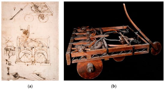
Figure 13.
(a) Manuscript of the self-propelled vehicle, Codex Atlanticus, f. 812 r (1478–1480), Ambrosiana Library of Milan, [56]; (b) Model at the National Museum of Science and Technology of Milan, based on the Canestrini Model [57].
Used as a theatrical machine that moved by itself, in both straight and curved directions, he made an impression at the court parties of the Duke of Milan Ludovico Sforza (Vigevano 1452–Loches 1508), and later at the French court of King Francis I (Cognac, 1494–Rambouillet, 1547).
In 2004, after several studies carried out in the Science History Museum in Florence, directed by Italian historians and researchers Paolo Galluzzi (Florencia 1942–) and Carlo Pedretti (Bolonia 1928–Lamporecchio 2018), with the clarifying contributions from the American robotics professor Mark Elling Rosheim, who digitalised all the necessary parts, it was possible to put into operation the automobile, giving actual feasibility to the solution that Leonardo projected more than 500 years ago.
7. Conclusions
The figure of Leonardo da Vinci grows as we look deeper into his work. He was a master of painting, delved into physics and anatomy, designed military and industrial machines, designed buildings and planned cities, and left a huge written work. However, the way in which he protected or concealed his findings and the fragmentation, and even loss of his written work caused by his heirs, along with many of his innovations being too advanced for his time, led to the opinion that much of Leonardo’s scientific-technical work was speculative.
In this paper, some of the main contributions of Leonardo da Vinci in the field of object and artifact design have been analysed. After reviewing Leonardo’s main codices and manuscripts regarding the design of instruments and machines, and mentioning some of the main scholars of his work, it focuses on analysing the foundations on which he supported his work as a designer.
In the third section, from a conceptual approach, the principles of generating solutions most used by Leonardo have been studied; inspiration by nature, the organic vision of mechanisms, analysis to decompose problems and synthesis for the integration of the designed object, the analogies with pre-existing designs, and the economy in the design by suppressing the superfluous. After that, these design approaches have been correlated with some of the existing theories that propose the design of technical systems as a scientific discipline. Afterwards, it has been analysed how Leonardo applied the principles of observation and experimentation to obtain the physical laws necessary to determine the mechanical and structural resistance of the designs developed by him.
In the following sections, a more applied approach has been adopted, and we have studied how Leonardo made contributions in the techniques of graphic representation (new exploded diagrams, family charts and bird’s-eye maps) and the instruments that he created or improved to increase the precision in the plot (compasses), in the visualization and representation of objects in perspective (prospectograph) and the measurement tools (odometer and pedometer).
Finally, we have presented the development of equipment and technical devices (the crank lift, hammer for piling, mechanical jacks, and even the first self-propelled vehicle), many of them designed to improve the effectiveness and efficiency of the projects in which Leonardo was involved.
All these advances that he made in techniques, instruments, and tools allowed his designs to be better than those of his contemporaries, and many of them could not be materialized at the time for lack of technology and adequate materials.
There is no doubt that technological development (materials, their processing, construction and manufacturing technologies, etc.) makes it possible to make reality what was considered impossible in the 15th century, and therefore many of the designs generated by the prodigious mind of Leonardo were unviable in his time. However, section six has shown how some of his proposals for machines, mechanisms, and instruments were put into practice and continue to be used today, while other designs have only been executed more recently as proof of his vision and resourcefulness.
Thus, the opinion of the university professor, art critic and director of the “Museo Ideale Leonardo da Vinci”, Alessandro Vezzosi (Italy, 1950), is reinforced. He states: “Da Vinci’s work is unmatched in the history of scientific and technological illustration, not only for his way of exposing procedures without endless and boring demonstrations, but also as a work of art, the creation of the designer” [28].
Author Contributions
Investigation, E.C.-M.; Conceptualization, E.C.-M., P.F.-G., S.F.C.-R.; Project administration, S.F.C.-R.; Supervision, S.F.C.-R.; Validation, P.F.-G.; Visualization, P.F.-G.; Writing—original draft, E.C.-M. All authors have read and agreed to the published version of the manuscript.
Funding
This research received no external funding.
Conflicts of Interest
The authors declare no conflict of interest.
References
- Pahl, G.; Beitz, W.; Feldhusen, J.; Grote, K.H. Engineering Design, A Systematic Approach, 3rd ed.; Springer: London, UK, 2007. [Google Scholar]
- Da Vinci, L. Codex Atlanticus; Biblioteca Ambrosiana: Milan, Italy; Available online: http://www.leonardo-ambrosiana.it/en/il-codice-atlantico/ (accessed on 4 May 2020).
- Da Vinci, L. Arundel Codex; British Library: London, UK; Available online: http://www.bl.uk/manuscripts/FullDisplay.aspx?ref=Arundel_MS_263 (accessed on 8 May 2020).
- Da Vinci, L. Madrid Codices. Biblioteca Nacional de España (National Library of Spain): Madrid, Spain; Available online: http://leonardo.bne.es/index.html (accessed on 15 May 2020).
- Da Vinci, L. Windsor Royal Collection Manuscripts; Royal Library of Windsor: Windsor, UK; pp. 1478–1518. Available online: https://www.royalcollection.org.uk/collection (accessed on 8 May 2020).
- Da Vinci, L. Paris Manuscripts; Institut de France; pp. 1487–1492. Available online: https://archive.org/details/lesmanuscritsdel00leonuoft (accessed on 12 May 2020).
- Ravaisson-Mollien, C. Les Manuscrit de Léonard de Vinci; The Warburg Institute: Paris, France, 1881. [Google Scholar]
- Galluzzi, P. Renaissance Engineers: From Brunelleschi to Leonardo da Vinci; Giunti Editore: Firenze, Italy, 1996. [Google Scholar]
- Pedretti, C. Leonardo: Le Macchine; Giunti Editore: Firenze; Italy, 1999. [Google Scholar]
- Capra, F. The Science of Leonardo; Doubleday: New York, NY, USA, 2007. [Google Scholar]
- Braha, D.; Maimon, O. The Design Process: Properties, Paradigms, and Structure. IEEE Trans. Syst. Man Cybern. Part A Syst. Hum. 1997, 27, 146–166. [Google Scholar] [CrossRef]
- Accreditation Board for Engineering and Technology (ABET). Criteria for Accrediting Engineering Programs, 2019–2020. Available online: https://www.abet.org/accreditation/accreditation-criteria/criteria-for-accrediting-engineering-programs-2019-2020/#definitions (accessed on 28 July 2020).
- Taglialagamba, S. Machines et ornament chez Léonard. In Cahier de l’Ornament; Caye, P., Solinas, F., Eds.; De Luca Editori d’Arte: Roma, Italy, 2016. [Google Scholar]
- Veltman, K.H. Leonardo da Vinci: A review. Leonardo 2008, 41, 381–388. [Google Scholar] [CrossRef]
- Blessing, L. What is this thing called Design Research? In Proceedings of ICED 03, Research for Practice; Design Society: Stockholm, Sweden, 2003. [Google Scholar]
- Cross, N. Engineering Design Methods, Strategies for Product Design; John Wiley and Sons: Chichester, UK, 2000. [Google Scholar]
- García de Zuñiga, E. Leonardo da Vinci. Aforismos; Espasa Calpe S.A.: Madrid, Spain, 2005. [Google Scholar]
- Pigem, J. Leonardo da Vinci, El visionario de la ciencia. In Historia—National Greografic; RBA: Barcelona, Spain, 2013. [Google Scholar]
- Kemp, M. Leonardo; Oxford University Press: Oxford, UK, 2004. [Google Scholar]
- Weber, C. Theory of Technical Systems (TTS)—Its role for design theory and methodology and challenges in the future. In Proceedings of AEDS Workshop at Pilsen; AEDS Workshop: Pilsen, Czech Republic, 2008. [Google Scholar]
- Verein Deutscher Ingenieure (VDI). VDI-Guideline 2221: Systematic Approach to the Design of Technical Systems and Products, English version of [VDI 2221]; VDI: Düsseldorf, Germany, 1987. [Google Scholar]
- Hubka, V.; Eder, W.E. Design Science, Introduction to the Needs, Scope and Organization of Engineering Design Knowledge; Springer: London, UK, 1996. [Google Scholar]
- Suh, N.P. The Principles of Design; Oxford University Press: New York, NY, USA, 1990. [Google Scholar]
- Suh, N.P. Axiomatic Design; Oxford University Press: New York, NY, USA, 1990. [Google Scholar]
- Innocenzi, P. Leonardo and the Design of Machines. In Proceedings of the 2nd International and Interdisciplinary Conference on Image and Imagination (IMG 2019); Advances in Intelligent Systems and Computing; Springer: Cham, Switzerland, 2020; Volume 1140, pp. 36–46. [Google Scholar] [CrossRef]
- Taglialagamba, S. Leonardo “designer” alla corte di Milano. Ordine, Bellezza e Invenzione. Art Doss. 2015, 1, 60–65. [Google Scholar]
- Pedretti, C. Leonardo Architetto; Mondadori Electa: Milano, Italy, 1981; pp. 324–344. [Google Scholar]
- Vezzosi, A. Leonardo Da Vinci, Ciencia y Arte Del Universo; Blume: Barcelona, Spain, 2011. [Google Scholar]
- Oliveira, A.R.E. The Mechanical Sciences in Leonardo da Vinci’s Work. Adv. Hist. Stud. 2019, 8, 215–238. [Google Scholar] [CrossRef][Green Version]
- Pedretti, C. Leonardo da Vinci (Leonardo: Art and Science); TAJ Books: Surrey, UK, 2004. [Google Scholar]
- Laurenza, D.; Taddei, M.; Zanon, E. Atlas Ilustrado de las Máquinas de Leonardo; Introduction by Paolo Galluzi; Susaeta Ediciones: Madrid, Spain, 2006. [Google Scholar]
- Nicholl, C. Leonardo da Vinci: Flights of the Mind; Penguin Books: London, UK, 2005. [Google Scholar]
- Gancedo, C. Once Maquinas e Ingenios de Leonardo Da Vinci interpretados por Carlos Gancedo; Introduction by Soledad Álvarez; Fundación Museo Evaristo Valle: Gijón, Spain, 2011. [Google Scholar]
- Jaramillo, H.E. Un análisis de la Resistencia de Materiales a partir de los postulados de “Consideraciones y Demostraciones Matemáticas sobre dos Nuevas Ciencias” de Galileo Galilei. Lámpsakos 2011, 5, 53–59. [Google Scholar] [CrossRef][Green Version]
- Galluzzi, P. The strange vicissitudes of Leonardo’s manuscripts. In The UNESCO Courier: A Window Open on the World; Unesco: Paris, France, 1974; pp. 4–8. Available online: https://en.unesco.org/courier/octobre-1974/strange-vicissitudes-leonardo-s-manuscripts (accessed on 2 August 2020).
- Truesdell, C. Ensayos de la Historia de la Mecánica; Editorial Tecnos: Madrid, Spain, 1975. [Google Scholar]
- Antoccia, L.; Chastel, A.; Chianchi, M.; Galluzi, P.; Laurenza, D.; Papa, R.; Pedretti, C. Leonardo, Arte e Scienza; Giunti Editore: Firenze, Italy, 2000. [Google Scholar]
- Reciprocating machine for weight lifting (Argano), Codex Atlanticus f. 30 v, (1478–1480). Available online: https://commons.wikimedia.org/wiki/File:Reproduction_of_page_from_notebook_of_Leonardo_da_Vinci_showing_a_geared_device_assembled_and_disassembled_LCCN2006681098.jpg (accessed on 10 May 2020).
- Model at the Museum of Science and Technology of Milan. Available online: https://commons.wikimedia.org/wiki/File:Argano_sollevatore_pesi_Leonardo_Museo_scienza_e_tecnologia_Milano.jpg (accessed on 10 May 2020).
- Map of the Val di Chiana, Royal Collection, RLW 12278, (1502–1504). Available online: https://commons.wikimedia.org/wiki/File:Val_di_Chiana.jpg (accessed on 8 May 2020).
- Gómez-Senent, E.; Santamarina, J.L.; Chiner, M.; Aragonés-Beltrán, P.; Capuz-Rizo, S. The design dimensions, a design theory proposal. In Proceedings of the International Conference on Engineering Design ICED 97; ICED: Tampere, Finland, 1997. [Google Scholar]
- Ricart, J.; González, A.; Tello, A.; Ribot, S.; Miralles, C.; Catazine, S.; Soriano, J.; del Vado, C. Grandes Maestros de la Pintura; Sol 90 S.L.: Barcelona, Spain, 2006. [Google Scholar]
- Reproduction of a compass designed by Leonardo. Available online: https://commons.wikimedia.org/wiki/File:Compas_Léonard_de_Vinci.JPG (accessed on 8 May 2020).
- Proportional or reduction compass. Forster Codex I f. 45 (1485). Available online: https://commons.wikimedia.org/wiki/File:Reduction_Compass_Leonardo.jpg (accessed on 8 May 2020).
- Parabolic Compass. Codex Atlanticus f. 1093 r. Available online: https://upload.wikimedia.org/wikipedia/commons/archive/0/03/20171027130237%21Leonardo_parabolic_compass.JPG (accessed on 8 May 2020).
- Taglialagamba, S. Leonardo and Arquitecture; CB Edizioni: Poggio a Caiano, Italy, 2012. [Google Scholar]
- Detail of the Codex Atlanticus f. 5 r. Enlarged detail of the prospectograph being used by Leonardo. Available online: https://commons.wikimedia.org/wiki/File:Codice_Atlantico_-_Perspectograph.jpg (accessed on 8 May 2020).
- Study ot two odometers. Codex Atlanticus, f. 1b r. Available online: https://commons.wikimedia.org/wiki/File:Odomètre-Léonard.jpg (accessed on 10 May 2020).
- Odometer model. Museo Nazionale della Scienza e della Tecnologia Leonardo da Vinci. (National Museum of Science and Technology of Milan). Available online: https://commons.wikimedia.org/wiki/File:Odometro_a_carriola_-_Museo_scienza_tecnologia_Milano_09908_01.jpg (accessed on 10 May 2020).
- Pugno, N.M. The commemoration of Leonardo da Vinci. Meccanica 2019, 54, 2317–2324. [Google Scholar] [CrossRef]
- Orlando, E.; Cinotti, M.; Rizzati, M.L. Leonardo. Colección de Grandes Maestros del Arte; Marin: Barcelona, Spain, 1977. [Google Scholar]
- Study for the mechanism of a manual lift (1495–1497), Madrid Codex I, f. 9 r. Available online: https://commons.wikimedia.org/wiki/File:Ascenceur_à_manivelle-Léonard.jpg (accessed on 10 May 2020).
- Study of a piling machine. Codex Atlanticus, f 785, Ambrosian Library of Milan. Available online: https://commons.wikimedia.org/wiki/File:Sonnette-Léonard.jpg (accessed on 10 May 2020).
- Model of Leonardo’s pile machine, at the National Museum of Science and Technology of Milan. Available online: https://commons.wikimedia.org/wiki/File:Battipalo_-_Museo_scienza_tecnologia_Milano_00040_01.jpg (accessed on 10 May 2020).
- Detail of a mechanical jack, Codex Atlanticus, f. 0998 r, Ambrosian Library of Milan. Available online: https://commons.wikimedia.org/wiki/File:Cric-Léonard.jpg (accessed on 15 May 2020).
- Manuscript of the self-propelled vehicle, Codex Atlanticus, f. 812 r (1478-1480), Ambrosiana Library of Milan. Available online: https://commons.wikimedia.org/wiki/File:Leonardo_da_vinci,_Automobile.jpg (accessed on 15 May 2020).
- Model of the self-propelled vehicle, at the National Museum of Science and Technology of Milan. Available online: https://commons.wikimedia.org/wiki/File:Carro_semovente_-_Museo_scienza_tecnologia_Milano_09082_02.jpg (accessed on 15 May 2020).
© 2020 by the authors. Licensee MDPI, Basel, Switzerland. This article is an open access article distributed under the terms and conditions of the Creative Commons Attribution (CC BY) license (http://creativecommons.org/licenses/by/4.0/).