Abstract
This is the second of two companion articles which aim to address the research on architecture and steel. In the first article, some architectural projects were analyzed to show the potentiality to conjugate architectural conception and steel structures (in sight), as well as to show the contribution and influence from architectural history. As a result of the previous work, this second article discusses the development of an innovative prototype in steel structure, which constitutes a modular system applied for a single-family housing. In this prototype, steel is part of the design concept, not only as a structural element, but also as an aesthetic element. The needs of contemporary “living” are reinterpreted, considering all the changes and cultural influences due to globalization, compared with the living in Portuguese popular architecture, with its simplistic character and minimal spaces, and referring to a place. The proposed modular system, which is applied repeatedly, shows a huge potential for reorganizing, in a short period of time, urban areas with housing shortages in cases of emergency, while respecting population needs and providing construction quality. This Prototype Model, which combines the architectural concept with the lightweight character of steel structures, aims to provide an “other” way of “living”. It transmits “harmony” both in the experience of the interior space and in its relationship with the outer space, respecting the cultural references. In this study, the prototype is applied to popular Portuguese schist architecture, combining the basic structuring idea and the way how the project develops for the application of the conceptual and constructive process, thus relating two periods of architecture.
1. Introduction
Following the study presented in the first companion article [1], this article presents a modular system in steel structure with equal angles steel profiles, in Greek cross shape, for the conception of an architectural prototype.
This investigation is based on the analysis of several housing architecture projects, belonging to the “Modern and Contemporary Movement” and built with steel structures in sight, using profiled systems. The analysis consisted of understanding their cultural characteristics and their relationship with the place/space, form and structure, typology, scale, and living and cultural characteristics (identity of the place) [1,2]. Such case studies included the following ones: Le Corbusier Center in Zurich, 1961–1967 [3]; the Experimental House by Walter Gropius for the Werkbund exhibition in Stuttgart (house 17), 1927 [4]; the Meudon Houses by Jean Prouvé, Paris, 1949 [5]; the Steel Housing by Cedric Price, 1967, with a simple model, structure, and connections [6]; the Michael and Patty Hopkins House, 1975–1976 [7]; the Yacht house by Richard Horden, New Forest, England, 1984 [8]; and CSH#8 by Charles and Ray Eames, Eames House, Santa Mónica, Califórnia, 1945–1949 [9], among other studied examples of single-family housing with different structural solutions and different options of wall materials.
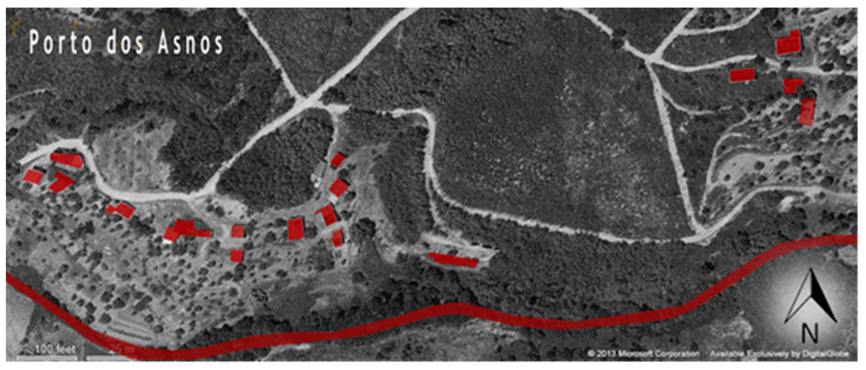
The choice of the place for the exemplification and materialization of the prototype followed the study of the “Portuguese Popular Architectural Culture and Ways of Living”. From this study, the desire arose to apply the model in a place abandoned by time, where the existing ruins were houses in the past, with small dimension but with high cultural load. The place is located in a small valley named “Porto de Asnos”, Fundão, Portugal, with a river at the foot of the mountainside which organizes the housing cluster in an organic line along it (Figure 1).
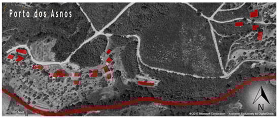
Figure 1.
Deployment plan for the cluster along the waterline.
In this housing cluster, the living space is characterized by the identity of those who built these small houses, which can be compared to Le Corbusier’s concept of “living machines”, as they served to respond to the functional needs and economic possibilities at the time. They were organized in the territory in a simple way, but somehow carefully along the river.
From the analysis of the place, in combination with the study of Portuguese popular architecture and all the references in the history of architecture, the modular steel system arises. The prototype is described throughout this article, starting from the living space, followed by its relationship with the place and its constructive development.
Some phases of the project’s development are addressed, from the study of “living”, through the definition of the structural grid, the definition and characterization of the complete structural system, and ending with some details about the structural calculations.
2. The Projected Living Space
For the conception of the architectural project, the factors of delimitation of the space and its interior/exterior relationship, whether physical or visual, allow the architect to design intimate spaces through the limits created by the proximity and distance between the new and existing. The dimensions of the spaces were systematically designed, in order to relate each functional space with the ruins, which served as a scenographic element and in which part of the walls of the preexistence divides the spaces and another part creates patios, respecting the solar orientation of the place and providing natural lighting and ventilation. The concept of “living machine” implemented by Le Corbusier is used here as one of the key ideas to create the standard model, to facilitate the necessary functions of living today.
In his work “Genius Loci-paesaggio ambiente architettura”, Christian Norberg-Schulz describes the importance of the relation of place and its identity [10]. For the author, in his reading of the place, all the elements of the surrounding nature are part of it and are interpreted as part of reality.
The conceptual idea for the organization of plans, for the recovery of the ruins of the place, and which was tested in one of them as a prototype in this study, involves reading the interior space of the preexistence and its relationship with the outside. This allows us to define the functions of “living”, which will be protected within the abandoned “scenario”, but keeping the poetic essence of forgotten times, and to project to the exterior the semi-public and “public” spaces, with the aim of being able to contemplate all the natural surroundings and the relationship between two complementary ways of living.
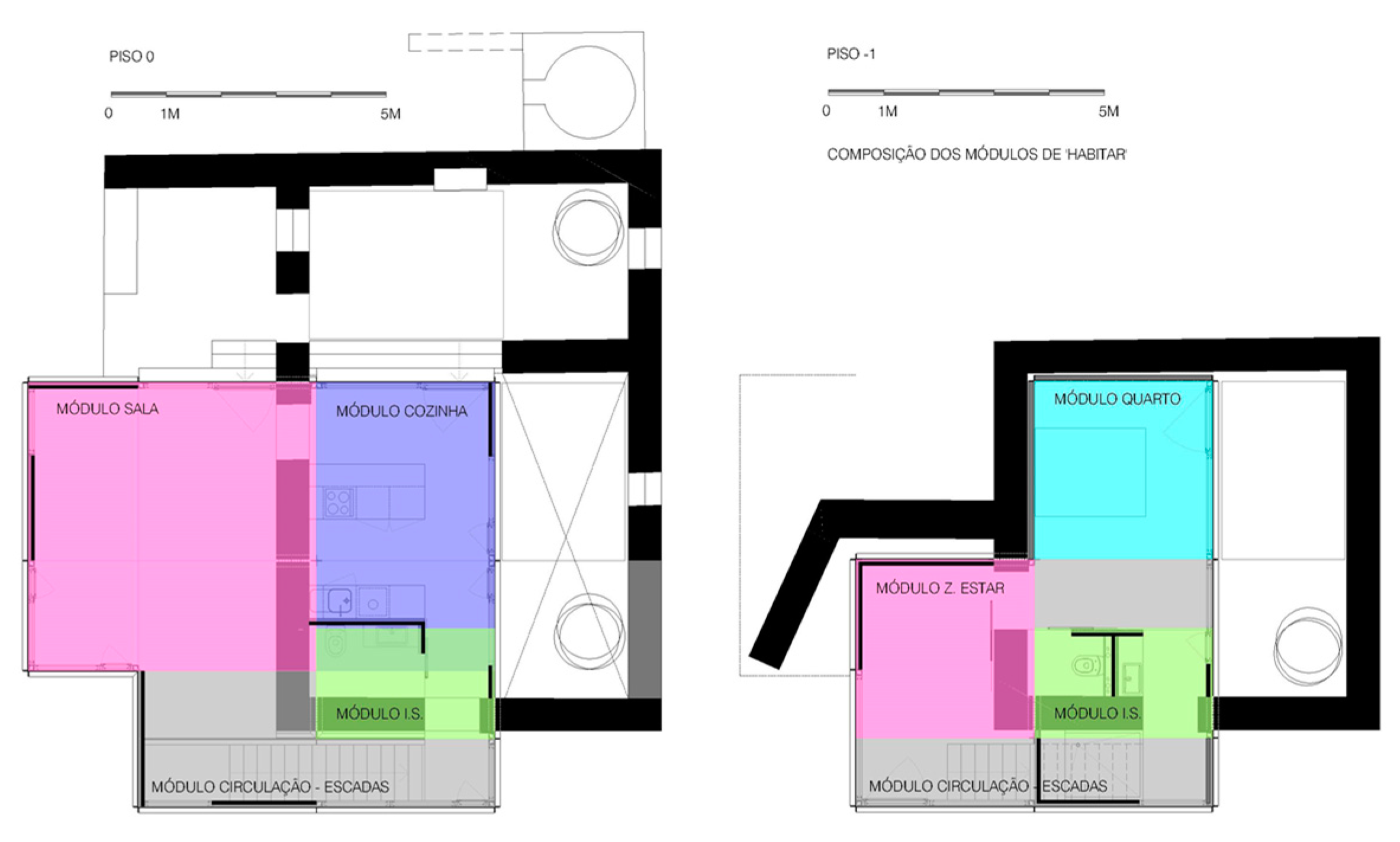
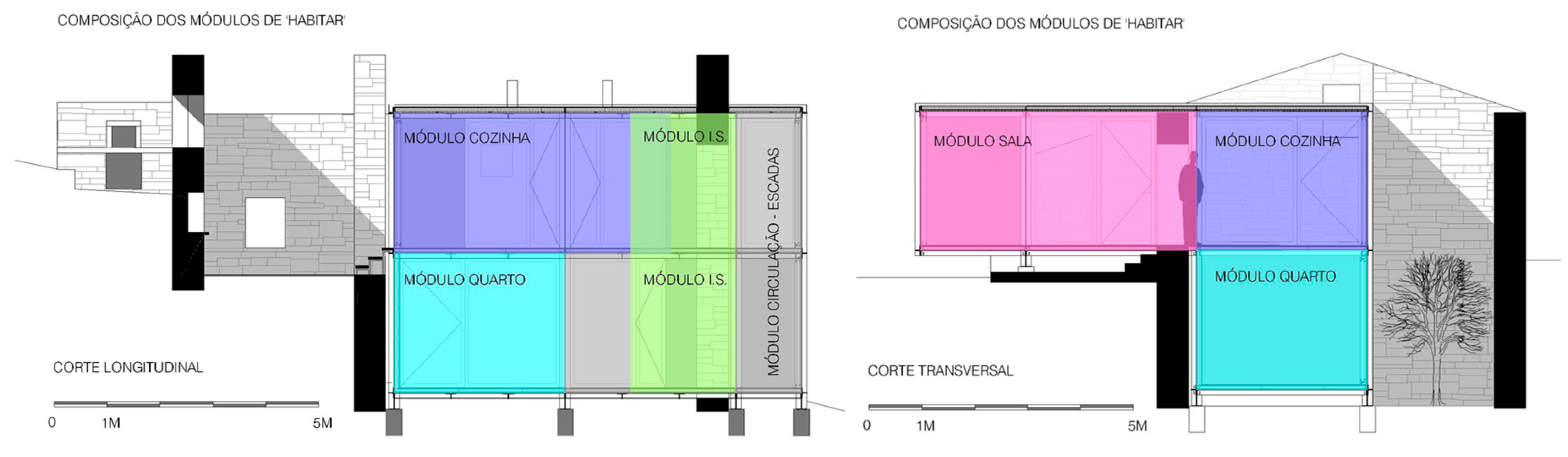
For the organization and separation of the divisions, simple opaque plans and sliding doors are used (Figure 2 and Figure 3). For the dwelling closure, glazings are proposed, in addition to some simple opaque plans. The opaque and glazed plans are positioned to allow for a better functionality and circulation of spaces, as the architect Mies Van der Rohe used in his projects. This allows for a better interior and exterior relationship.
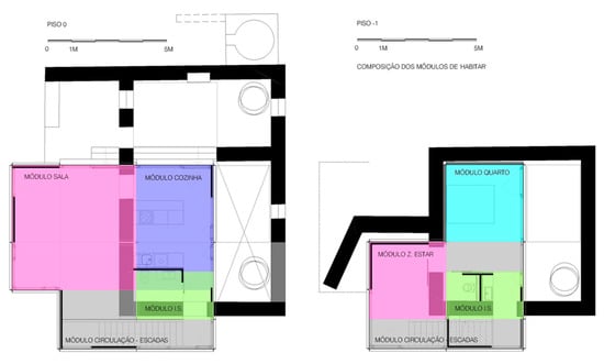
Figure 2.
Schemes of the composition of the “living” modules (plans).

Figure 3.
Schemes of the composition of the “living” modules (cuts).
Private and semi-private spaces are placed inside the ruins with some punctual visual relations with the outside, showing a greater relationship with the patios that emerged from the conceptual design, and protecting these areas as a “coat” and allowing them to extend the interior/exterior (Figure 4).
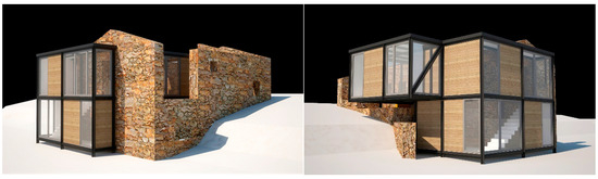
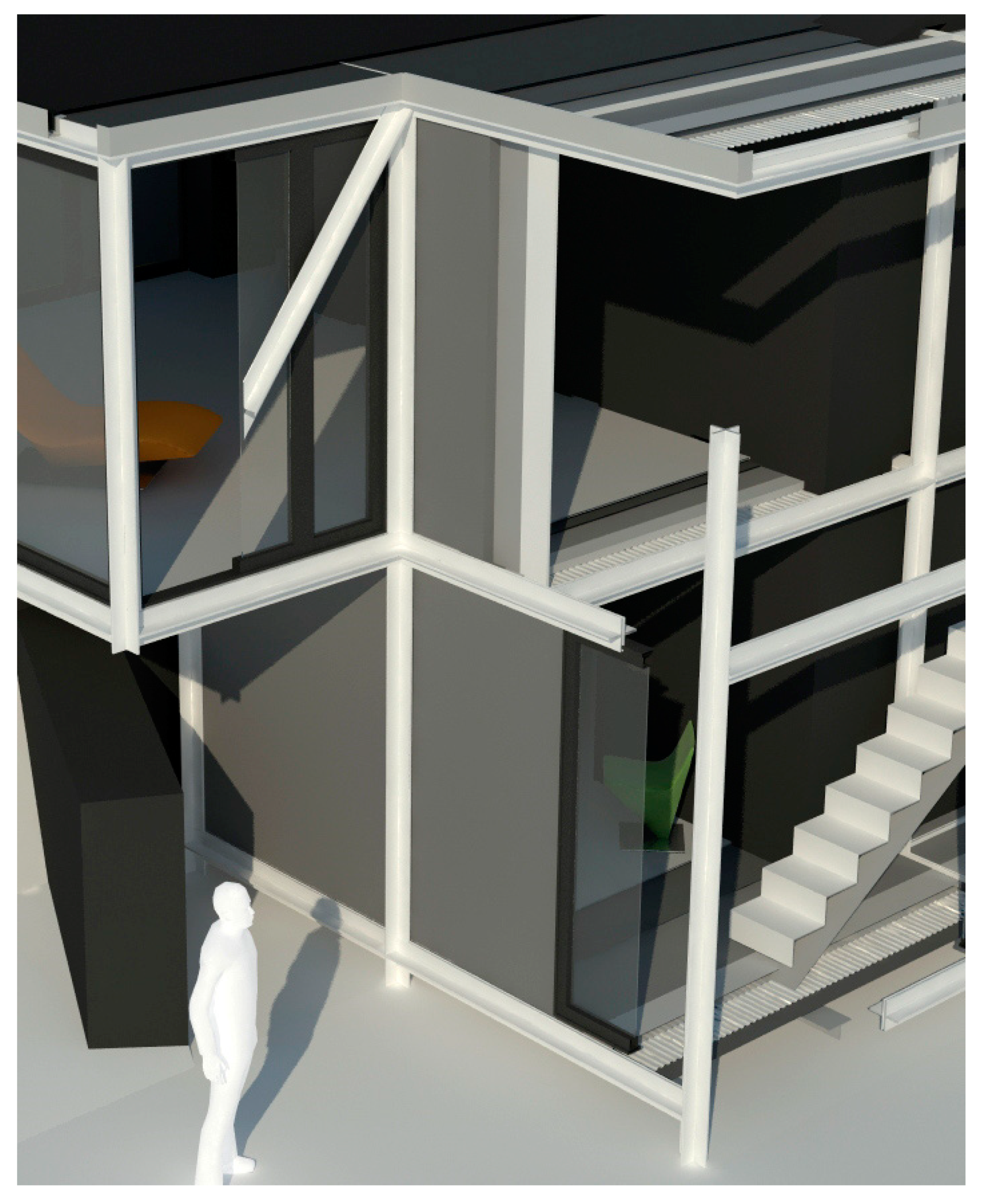
Figure 4.
Three-dimensional images of the prototype: southeast and southwest.
In this project, the concept of patio is drawn from the ruins’ walls, being a scenography giving to the space the essence of the combination between the new and the existing. The space is not closed in this exterior space, as there exists a physical or visual relationship between these two spaces. The physical circulation in the living space (interior) is thought so that an interior/exterior ruin path exists and is designed to take advantage of all the openings existing in the preexistence. Thus, we enter the house through the existing porch, which opens to a living room or through the patio (proposed), which connects to the kitchen area, always with the notion that a direct relationship between these two buildings exist. The “L’Immeuble–Villa” model, the “Pavillon de L’Esprit Nouveau”, Le Corbusier implemented on a collective housing scale, is the idea of a patio coupled with a housing cell in order to offer a better quality of life to those who lived in these apartments. In the Patio Houses in Berlin, Mies Van der Rohe created the courtyards between the walls and almost always at one end of the land or designing the house in a way to create more than one patio.
3. Definition of the Structural Grid
The conceptual idea of connecting habitable cells to create an architectural space led to the research and study of a structure that was part of the creative and constructive process. The type of steel structure and the type of standard steel profile were chosen and designed according to the concept, giving rise to Greek cross columns that easily allow for the connection of each division in their corners.
The conception and structuring of the system presented in this research work is based on the modular dimensional coordination of the pavement modules, designed on the base of the golden rectangle theories, which were applied in important works throughout the history of architecture. The modules do not all present the same dimensions, although they were defined in strict proportion from the “Fibonacci theory”. This allows for each space to have its own defined area and be freed from the consecutive structure. In addition, it allows for a great versatility to define the heights of the floors (right foot), maintaining a conceptual freedom within the defined standards.
A standard steel profile, composed with four equal angles steel profiles L100 × 100 × 8, was chosen to create a lightweight structure with columns and beams, in the composition with the conceptual module (Figure 5). This type of profile, widely used for roofing and bracing systems in steel structures, is not commonly used as a constructive solution for structural lattices, but it seemed to be the ideal solution for this conceptual and creative study.

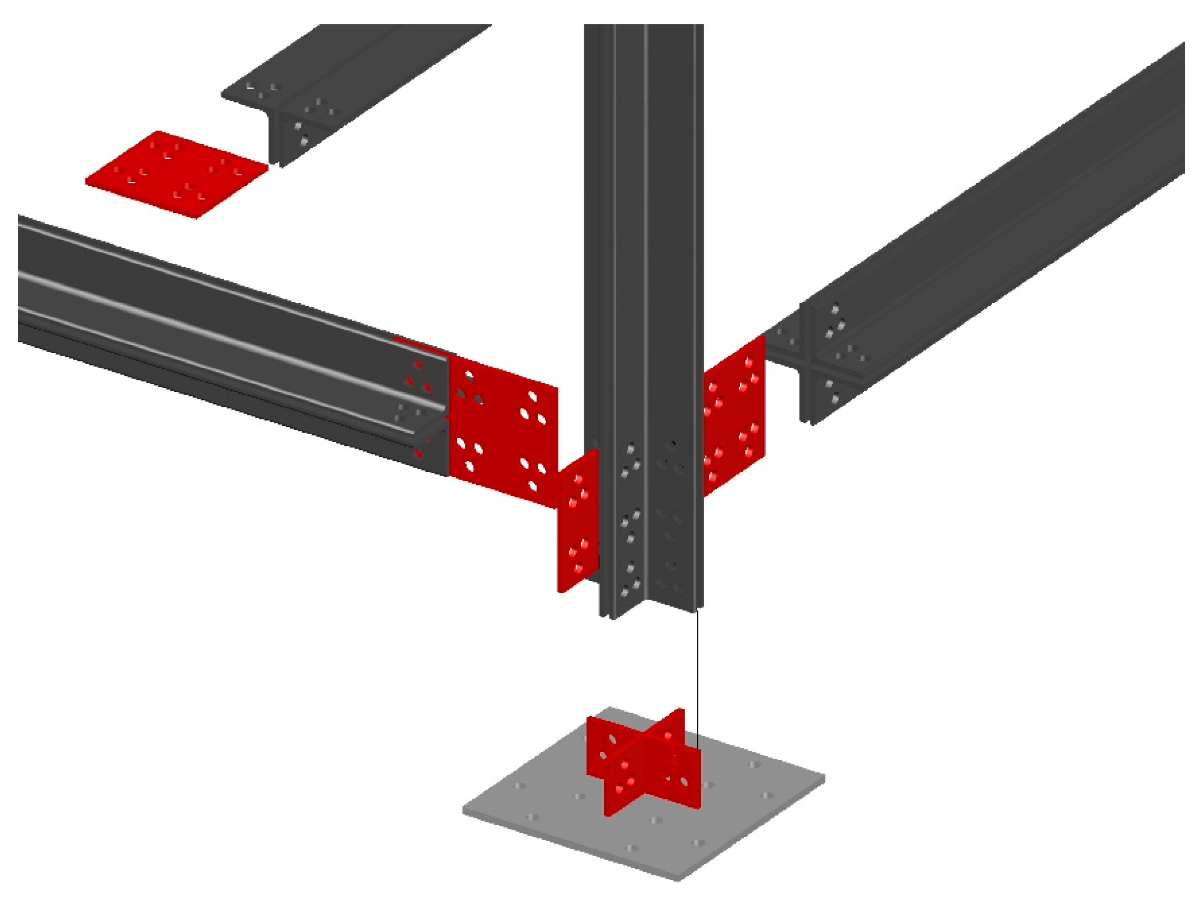
Figure 5.
Connection of columns and beams with Greek cross shape—Patent [11].
This type of profile was used by the architect Mies Van der Rohe in the columns for the German Pavilion in Barcelona. The profile was designed to obtain a subtle column, without great volume and which, aesthetically, demonstrates the idea of his famous sentence “less is more”. The decision to leave the structure entirely in sight shows its delicate, sublime, rigorous, and, above all, resistant character.
The proposed construction system here uses only angle steel profiles for the main structure (columns, girders, secondary beams, and stairs), allowing us to minimize the diversification of steel profiles to be used and taking advantage of the repetitive profitability and use. This type of structural system, combined with the developed modular floor pattern, based on the desired area for each division and proportion ratio between them, allows us to develop different architectural compositions/sets, being a unique project adapted to a specific place.
A constructive system for a housing unit up to two stories was developed, based on the definition of spaces with specific living functions and according to the client and the project. Repetitions of the referred steel profiles are used in both vertical (columns) and horizontal (girders) directions. The secondary beams, connected (with bolts or welded) to the girders, are used to directly support the loads from the pavements. For such beams, two equal angles steel profiles are used to form an inverted-T cross section. All these elements, linked together, form a structural grid working as a flexible, yet resistant and solid, skeleton. This allows us to achieve a satisfactory degree of customization, in addition to a high degree of diversity for the final product.
4. Definition and Composition of the Structural System
The system is based on a minimum module of 2 × 2 m, which increases in proportion with the rule of the golden rectangle, in order to define the areas of the floors of each living space, and being able to reach a maximum of approximately 5 × 5 m (strictly 5.2361 m; these dimensions are possible to be used because, in steel construction, millimeters are used).
The fitting system of these pavement modules is made by the interconnection of the columns with Greek cross shape designs for two stories and composed with four equal angles steel profiles that are 100 × 100 mm wide and 8 mm thick. The height of the columns for a public space may be 3.24 m (according to the same proportion used for the floors—the golden rule applied to 2 × 2 m). For housing, the height is 2.76 m per floor (Figure 6 and Figure 7), with an additional minimum of 30 cm to account for the elevation from the ground, which can vary depending on the ground.
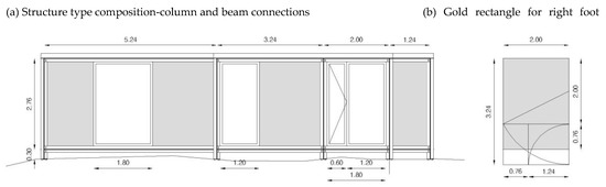
Figure 6.
Composition of the modules-elevation (connection between columns and beams).
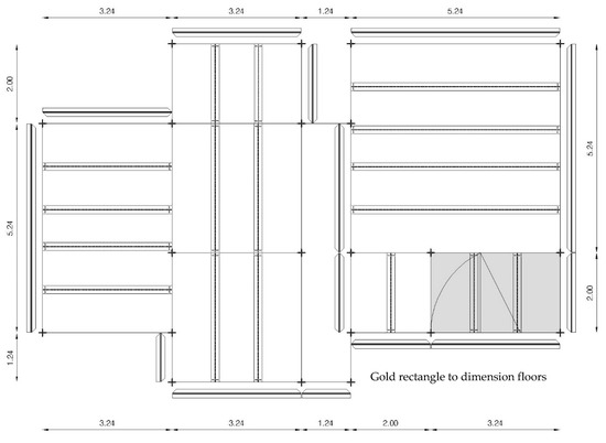
Figure 7.
Organization of pavement areas and their connection with columns and girders with Greek cross shape/secondary beams with T-shape—plan view.
This system also allows us to build cantilever parts (the designed model has a 2.10 m cantilever) by using two diagonal equal angles steel profiles as additional ties to help for the support. In some cases, steel cables can also be used.
The connection system to the columns (Figure 8) is made with high-strength bolts, class 8.8 and diameter 16 mm, according to Eurocode 3, and cut to the face, to hide the connection, or using cap nuts only on the elevations, in order to aesthetically assume the connection element.

Figure 8.
Three-dimensional image of the prototype, with the layers of materials on the walls, floors, and roof [2].
The structure of the pavements is a grid composed by girders and secondary beams. These last ones, composed with two equal angles steel profiles to form an inverted T-shape, directly support the loads from the pavement and are supported by the girders. The secondary beams, with approximate spacing of 1 m between axes, relate to bolts to the girders.
Since all the parts of the modular system are in sight, both internally and externally, it is necessary to protect the steel profiles from the weather.
The ground floor pavement, which is closest to the ground and placed on the secondary steel beams, consists of waterproofing fabric, profiled and metallized aluzinc sheet, thermal insulation (or sandwich panel), geotextile blanket, and marine plywood or “OSB” plates with final finishing (polystyrene sheets to receive the finishing, such as wood, microcement, ceramics, marble, granite, limestone, etc.).
The middle floor incorporates profiled aluzinc sheet in white color to be visible on the ceiling, thermal insulation (or sandwich panel), acoustic screen, marine plywood or OSB plates, and final finishing.
The roof incorporates aluminum profile sheets, vapor barrier, thermal insulation (or sandwich panel), marine plywood, and waterproof PVC screen for finishing with the gutter. All these materials are designed and cut at the factory, for posterior application on the construction site.
The wall panels are fixed with U-profiled rails fixed to the floor, on top of the thermal insulation, and bolted to the steel plate and L-shaped rails on the ceiling. The walls can be built in a U-shaped metal structure or wooden structure. An exterior coating material, thermal insulation inside, and other material for interior finishing will be applied. The window frames are bolted to the angle steel profiles of the columns and beams, as well as to the marine plywood fixed to the structure.
The steel structure is bolted to a non-structural concrete beam foundation with a 30 × 80 cm rectangular cross section, built with an estimated concrete volume of 2.5 m3.
It should be noted that the used cross section is not considered to have an optimized geometry to be used for beams. However, the used lightweight solutions for both the pavements and walls led to very low gravitational loads. The live loads for housing are not very high either. In addition, the maximum span used for the beams is less than 4 m, and rigid connections to the columns were used. For these reasons, the structural safety of the beams was checked and had with no problems, even considering snow and earthquake loadings.
5. Some Details of the Structural Calculation
5.1. Introduction
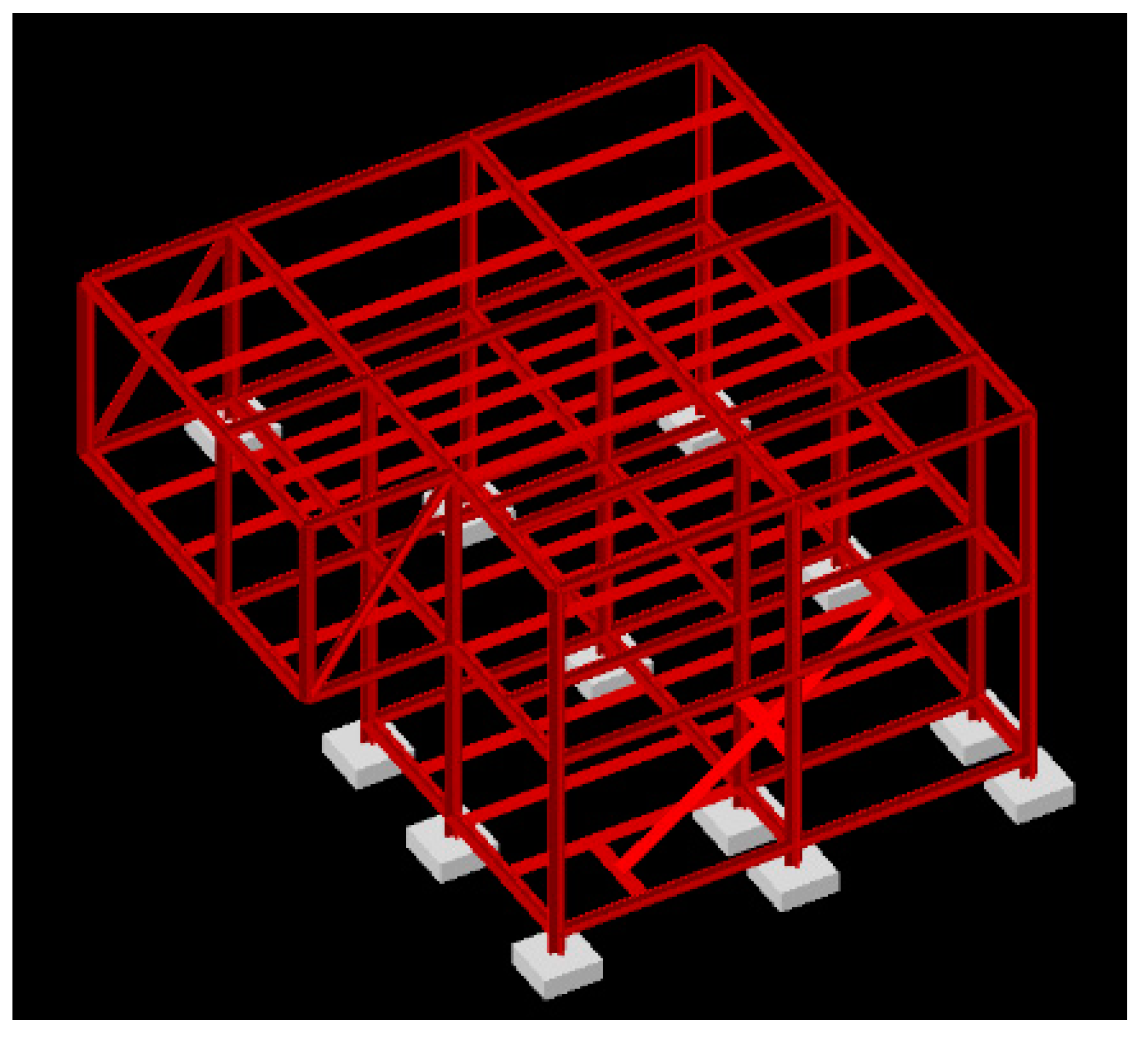
Figure 9 illustrates the 3D computational structural model for the prototype. Since this is a research project, the geotechnical conditions on the construction site were not clearly known. Hence, an admissible stress of 200 kN/m2 for the ground was considered to calculate the foundations in reinforced concrete. A direct foundation was adopted, consisting of isolated footings located at the depth specified by the architectural project. Since the structure is very light, no foundation beam was considered to link the footings in the structural model (although a non-structural foundation beam was proposed in the architectural project).
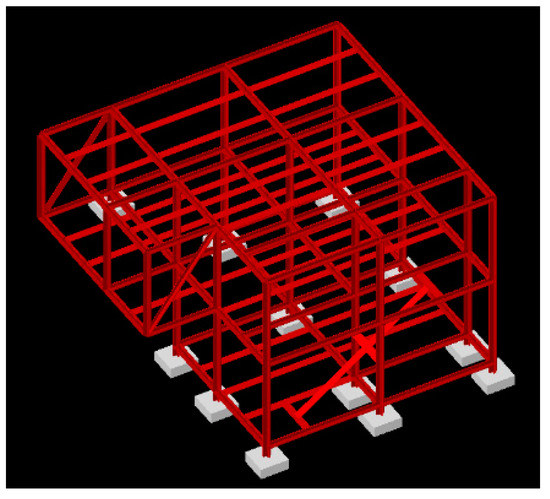
Figure 9.
Rendering of the structural model used to check the structure.
The adopted structural solution was strongly conditioned by the following factors: (i) architectural conditionings (imposed by the architectural project and includes all the necessary drawings-plans and cuts) and (ii) economical aspects.
Based on the previous conditionings, the chosen solution was a 3D framed steel structure with columns and principal beams (girders) composed with four interconnected equal angles steel profiles (4 × L-100-8) to form a Greek cross shape, rigidly connected with bolted joints. The floors and roof are built with a grid incorporating secondary steel beams composed with two interconnected equal angles steel profiles (2 × L-100-8) to form an inverted T-shape. These beams are supported by the floor and roof girders through rigid bolted joints. The diagonal ties used to support the cantilever part are composed with two interconnected equal angles steel profiles (2 × L-100-8) rigidly connected with bolts to the corners of the frames.
The loads from the superstructure are transmitted to the foundation ground through direct foundations made of isolated reinforced concrete footings for each column.
To check the structural safety, the prescriptions from the structural Eurocodes were used.
5.2. Actions
The loads acting on the structure can be classified as function of their duration with respect to the structure’s lifetime, namely in permanent and variable loads. The values considered for the density of the materials and applied distributed/linear loads are presented below.
5.2.1. Permanent Loads
- –
- Density of reinforced concrete: 25 kN/m3;
- –
- Density of structural steel: 78 kN/m3;
- –
- Coatings and coverings (according to the architectural project):
- –
- Roof slab: 1.0 kN/m2;
- –
- Pavement slab and circulations: 1.0 kN/m2.
- –
- Partition walls (according to the architectural project):
- –
- Util areas: 0.5 kN/m2.
- –
- Walls (according to the architectural project):
- –
- Exterior (includes glazing): 2.65 kN/m;
- –
- Interior: 1.3 kN/m.
5.2.2. Variable Loads
- Live Loads
- –
- Roof (not accessible terrace): 1.0 kN/m2;
- –
- Util areas + accesses: 2.0 kN/m2.
- Earthquake
The effects of the seismic load were considered through a 3D dynamic analysis. For this, the concept of response spectrum was used. The used response spectra to perform the analysis were quantified in terms of the maximum accelerations, as prescribed in the structural Eurocodes, which depends on the following factors: zone under study and where the house is built, the ground type in which the structure is founded, the type of earthquake to be considered (depending on the magnitude and focal distance), the damping coefficient for the structure (typically 2% for steel structures), and the required ductility class for the structure (considered normal for this study).
- iii.
- Wind
Considering the overall relatively small dimensions of the structure, with a large part of it protected by exterior stone walls, and since the seismic effect was considered, the effect of the wind load was neglected.
- iv.
- Temperature
The overall relatively small dimensions of the structure allow us to neglect the effect of thermal actions arising from climatic and operational conditions.
- v.
- Snow
Considering the altitude (about 650 m) and the territory zone of the construction place, it is necessary to consider the loading effect of the snow. The characteristic and distributed loading value to simulate the snow action, accounting for the previous factors and for the shape of the surface of the roof, is 1.63 kN/m2.
5.3. Combinations of Actions
The criteria used to check the structural safety are based on the quantification of design values (Sd), in which the simultaneous effects of the various actions acting on the structure are accounted for. The combinations of actions require us to fix the leading variable action, being the accompanying variable actions multiplied by corrective factors (ψ). In addition, both permanent loads and variable actions are majorated by partial factors (γ). The combinations of actions considered in this study account for the effect of actions of gravitational nature (permanent load (G), living load (Q), and snow (N)) and also the dynamic action due to earthquakes (E). In this study, two combinations of actions were considered: living load (Equation (1)) and earthquake (Equation (2)) as leading variable actions.
Sd = γGSG + γQ (SQ + ψ0NSN) = 1.35SG + 1.5 (SQ + 0.6SN)
Sd = SG ± γESE + ψ2QSQ = SG ± 1.5 SE + 0.2SQ, util areas
5.4. Materials
5.4.1. Structural Materials
The foundations are built by using concrete class C20/25 2a and steel rebars class S400). The steel structure is built by using steel profiles class S355.
The concrete must meet the requirements established in NP ENV 206 code and must also present the following mechanical properties established in Eurocode 2 for C20/25:
- –
- Characteristic value for the compressive strength: 20 MPa;
- –
- Design value for the compressive strength: 13.3 MPa;
- –
- Average value for the tensile strength: 2.2 MPa;
- –
- Average value for the elastic modulus: 29 GPa.
Hot-rolled ribbed steel bars are used, which must also present the following mechanical properties established in Eurocode 2 for S400:
- –
- Characteristic value for the tensile failure: 460 MPa;
- –
- Characteristic value for the tensile yielding: 400 MPa;
- –
- Design value for the tensile yielding strength: 348 MPa;
- –
- Average value for the elastic modulus: 200 GPa.
Hot-rolled steel profiles are used in the steel structure, which must also present the following mechanical properties established in Eurocode 3 for S355:
- –
- Design value for the tensile failure: 510 MPa;
- –
- Design value for the tensile yielding: 355 MPa;
- –
- Average value for the elastic modulus: 210 GPa.
5.4.2. Non-Structural Materials
Non-structural materials used in the construction of the prototype include waterproofing systems, coatings, etc., as defined in the architectural project. Moreover, concrete class C12/15.1 is used to level and regularize surfaces, such as the ground surfaces for the reinforced concrete footings.
5.5. Structural Analysis
The structural analysis, from which it was possible to obtain the internal forces in all members, was based on a 3D reticular model (Figure 9) under both dynamic and gravitational actions. For all structural members, the elastic properties were considered, associated with their geometrical properties. The analysis of the 3D structure, as well as the design of each structural member, was carried out by using computational techniques, namely by using the TRICALC software.
5.6. Safety Verification
In this study, the safety verification followed the general requirements stated in Eurocode 2 for the reinforced concrete foundations and Eurocode 3 for the steel structure including joints. The security verification was checked based on the concept of ultimate limit state and was performed by comparing the design values for the resistant calculation internal forces (Rd) with the design values for the acting calculation internal forces (Sd), in order to verify the following safety condition: Sd ≤ Rd. In addition, the deformation serviceability limit state was also checked, by limiting the deflection of each member to a maximum value corresponding to 1/500 of the span.
6. Conclusions
The development of the theoretical and applied model presented in this study allowed us to compile and address several topics inherent to the conceptual process of an architectural project, to create and justify an architectural object. This was based on a systematic and coherent research line, valuing the creative process so that it can be read/interpreted as architecture and not as a mere construction.
Starting from the analysis of all of these concepts, a modular system was developed in which the steel structure was a part of the creative and conceptual process. It was thought to be built in mass and adapted to each place, client, topography, and climate, in order to gain an individual identity for each situation, constituting a unique and differentiated project and built using the same modules designed for the applied model.
To validate the proposed modular system, as it was intended, a place with preexistences was chosen to implement the prototype. For this, it was necessary to perform a historical analysis of the existing construction, which is part of Portuguese popular architecture, and in an area where the most used construction material is schist. Hence, the Portuguese architectural culture, the ways of living at that time, with minimal spaces and few housing conditions, were analyzed. This allowed us to perform a spatial and formal analysis, as well as a typological and scale analysis, in order to show the living and cultural characteristics of this type of architecture, through the living and the relationship with the place, the relationship between the interior/exterior space, the boundary surfaces of space, and the applied structural and constructive system.
Based on the developed prototype, applied in a place with characteristics, it can be concluded that it is possible to integrate steel structures in the conceptual process, applied to housing. In addition, it is possible to industrialize the construction process, with a modular system, which can respond to the housing shortage in many countries, being possible to build quickly an urbanization with different housing compositions adapted to the needs of each family, in which monotony is not present.
It constitutes a perfectly viable solution for the recovery or rehabilitation of preexisting or old buildings, which has been the case study in this investigation, and can be customized for an individual client. The concept of individuality in this structural system is very present, because even starting from a model that is always the same, but with different dimensions for each “living” function, it is necessary to think each intervention as a unique and specific project for each place.
The prototype presented in this study led to the development of a national patent for the construction system entitled “MODULAR STRUCTURE IN STEEL PROFILE WITH EQUAL ANGLES, ‘L’, IN CROSS FORM”, registered with number 108119, at the National Institute of Industrial Property in Portugal. [11]
Author Contributions
I.D.D.C. developed the theoretical and applied model and wrote the article. L.F.A.B. performed the structural calculations and revised the article. All authors have read and agreed to the published version of the manuscript.
Funding
This research received no external funding.
Conflicts of Interest
The authors declare no conflict of interest.
References
- de Campos, I.D.; Bernardo, L.F.A. Architecture and Steel. Reflection and analysis on the use of steel structures (in sight) as a concept in the History of Architecture. Appl. Sci. 2020. in review. [Google Scholar]
- de Campos, I.D. Concepção Arquitectónica e Estruturas Metálicas em Habitação, Sistema Modular Espacial Aplicado (Architectural Conception and Steel Structures for Housing. Applied Spatial Modular System). Ph.D. Thesis, University of Beira Interior, Covilhã, Portugal, 2015; 291p. (In Portuguese). [Google Scholar]
- Archdaily. Último Edifício Projetado por Le Corbusier (Last building Designed by Le Corbusier). 2020. Available online: http://www.archdaily.com.br/br/918082/ultimo-edificio-projetado-por-le-corbusier-e-reaberto-em-zurique (accessed on 29 March 2020).
- PROYECTOS 7/PROYECTOS 8. Vivienda Experimental (Experimental House), Walter Gropius. 2020. Available online: http://proyectos4etsa.wordpress.com/2012/05/08/vivienda-experimental-para-la-werkbund-exhibition-walter-gropius-stuttgart-1927/ (accessed on 29 March 2020).
- PROYECTOS 7/PROYECTOS 8. Casas de Meudon. 2020. Available online: http://proyectos4etsa.wordpress.com/2012/04/05/casas-de-meudon-jean-prouve-meudon-paris-1949/ (accessed on 29 March 2020).
- Socks. 2020. Available online: http://socks-studio.com/2016/04/14/cedric-price-housing-research-1971-and-the-steel-house-1967/ (accessed on 29 March 2020).
- Hopkins Architects. Hopkins House. 2020. Available online: http://www.hopkins.co.uk/projects/7/85/ (accessed on 29 March 2020).
- HCL Architects. The Yacht House—Hampshire, UK. 2020. Available online: http://www.hcla.co.uk/projects/type/the-yacht-house (accessed on 29 March 2020).
- Koenig, G.; Eames, C.R. 1907–1978, 1912–1988, Pioneers of Mid-Century Modernism; Taschen: Cologne, Germany, 2015. [Google Scholar]
- Norberg-Schulz, C. Genius Loci—Paesaggio Ambiente Architettura; Mondadori Electa: Milan, Italy, 1979. [Google Scholar]
- de Campos, I.D. Patent NO. 108119. INPI—Instituto Nacional da Propriedade Industrial (National Institute of Industrial Property). Available online: https://justica.gov.pt/Registos/Propriedade-Industrial/Patente. (accessed on 4 December 2019).


© 2020 by the authors. Licensee MDPI, Basel, Switzerland. This article is an open access article distributed under the terms and conditions of the Creative Commons Attribution (CC BY) license (http://creativecommons.org/licenses/by/4.0/).