Article

Digital Triplet Approach for Real-Time Monitoring and Control of an Elevator Security System

1
Siemens Mechatronic Training Center, Dedan Kimathi University of Technology, 10100 Nyeri, Kenya
2
Faculty of Vehicle Systems and Production, Institute of Production (IFP), Technology Arts Science TH Koln, 50678 Köln, Germany
*
Author to whom correspondence should be addressed.
Submission received: 18 February 2020 / Revised: 14 April 2020 / Accepted: 15 April 2020 / Published: 21 April 2020

Abstract

:
As Digital Twins gain more traction and their adoption in industry increases, there is a need to integrate such technology with machine learning features to enhance functionality and enable decision making tasks. This has lead to the emergence of a concept known as Digital Triplet; an enhancement of Digital Twin technology through the addition of an ’intelligent activity layer’. This is a relatively new technology in Industrie 4.0 and research efforts are geared towards exploring its applicability, development and testing of means for implementation and quick adoption. This paper presents the design and implementation of a Digital Triplet for a three-floor elevator system. It demonstrates the integration of a machine learning (ML) object detection model and the system Digital Twin. This was done to introduce an additional security feature that enabled the system to make a decision, based on objects detected and take preliminary security measures. The virtual model was designed in Siemens NX and programmed via Total Integrated Automation (TIA) portal software. The corresponding physical model was fabricated and controlled using a Programmable Logic Controller (PLC) S7 1200. A control program was developed to mimic the general operations of a typical elevator system used in a commercial building setting. Communication, between the physical and virtual models, was enabled using the OPC-Unified Architecture (OPC-UA) protocol. Object recognition using “You only look once” (YOLOV3) based machine learning algorithm was incorporated. The Digital Triplet’s functionality was tested, ensuring the virtual system duplicated actual operations of the physical counterpart through the use of sensor data. Performance testing was done to determine the impact of the ML module on the real-time functionality aspect of the system. Experiment results showed the object recognition contributed an average of 1.083 s to an overall signal travel time of 1.338 s.

1. Introduction

As automation technology heads towards the new industrial revolution, i.e., Industrie 4.0, cyber physical systems are becoming the norm in modern industries [1]. The key feature of such systems being the integration of the physical set-up with their digital counterpart to realize what is known as a Digital Twin [2]. This digitisation concept is an enhancement of the traditional Production Life-cycle Management (PLM) method used to effectively administer the creation of products from design to market supply. The adoption of cyber-physical systems is seen in applications ranging from product life-cycle simulation, predictive maintenance, plant layout planning and process design optimisation [3,4].
In addition, current research efforts in industrial automation are aimed at using artificial intelligence and machine learning to enhance system performance. A survey conducted by Diez et al. [5] showed how data fusion and machine learning were gradually gaining attention in different industrial sectors. The application of artificial intelligence techniques to enhance the performance of Digital Twin systems results in what can be termed as ‘Digital Triplet’ [6].
This research aimed at creating a Digital Triplet control system for a three-floor elevator model as a proof of concept. The Digital Triplet enabled remote monitoring and control of the elevator as well as the inclusion of improved decision making through the use of object recognition, facilitated by a machine learning model. A Digital Twin of the three-storey elevator system was done using Siemens NX software. After design, the physical system was fabricated and programmed to achieve typical elevator functionality. Communication between the virtual and physical models was then established using the OPC-UA protocol. In addition to achieving typical elevator operation, object recognition was implemented through a camera to enhance the security features within the system. Testing was later done to determine the system performance characteristics.

2. Literature Review

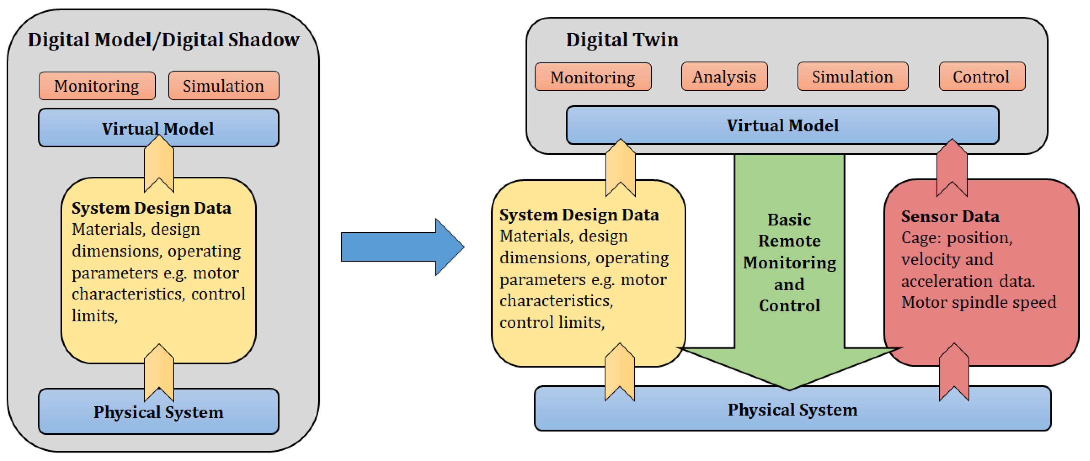
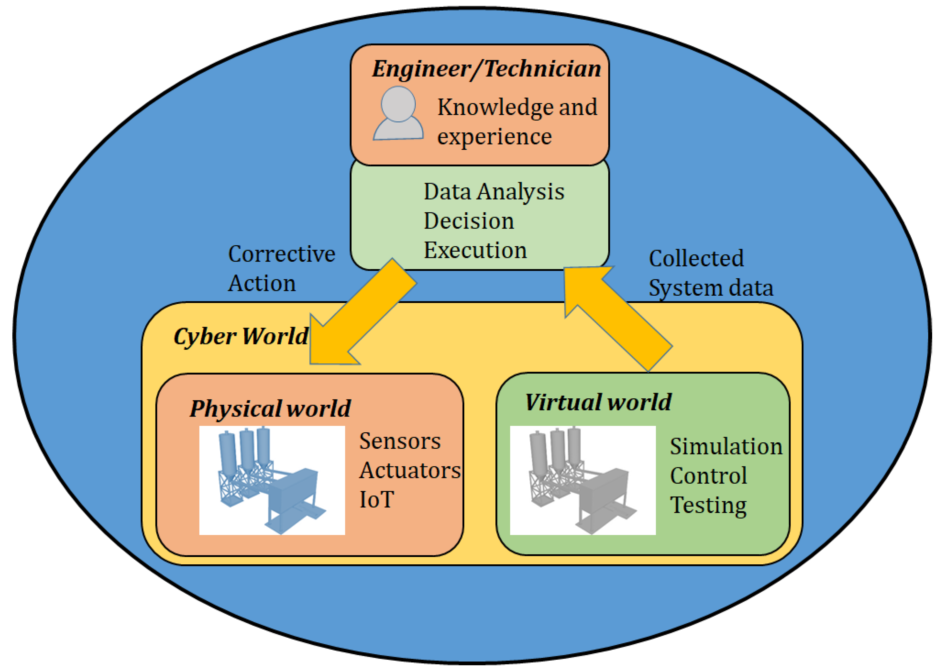
2.1. From Digital Twin to Digital Triplet

2.1.1. Development of Digital Twin Technology

The Digital Twin concept arose from the natural evolution of early forms of physical and digital object interfacing known as digital models and digital shadows. A digital model is defined as a virtual representation of a physical system without automatic data exchange between the two objects [4]. A digital shadow is an enhancement of the digital model since it introduces the integration of a one way communication channel between the physical system and its virtual counterpart. In such a system, the physical model can send data caused by a change in state to the virtual object, but the reverse is not possible [4,7].
A Digital Twin is distinct from the above mentioned, due to its full integration of information communication between the physical and virtual objects. A change in state in the physical object is registered in the virtual system and any applied change in state to the virtual system can affect the physical object [3,8]. Figure 1 shows the key elements contained in digital models, digital shadows and Digital Twins, highlighting the type of information flow involved in each.
Several key technologies are driving the increased adoption of Digital Twins in industry. These include but are not limited to, continuous and discrete simulation methods, communication protocols (OPC-UA and MQTT), Internet of things, Cloud computing, Big data and data fusion [4]. When integrated in CPS most Digital Twin applications include but are not limited to, layout planning, preventive maintenance and production planning and control [7,9,10].

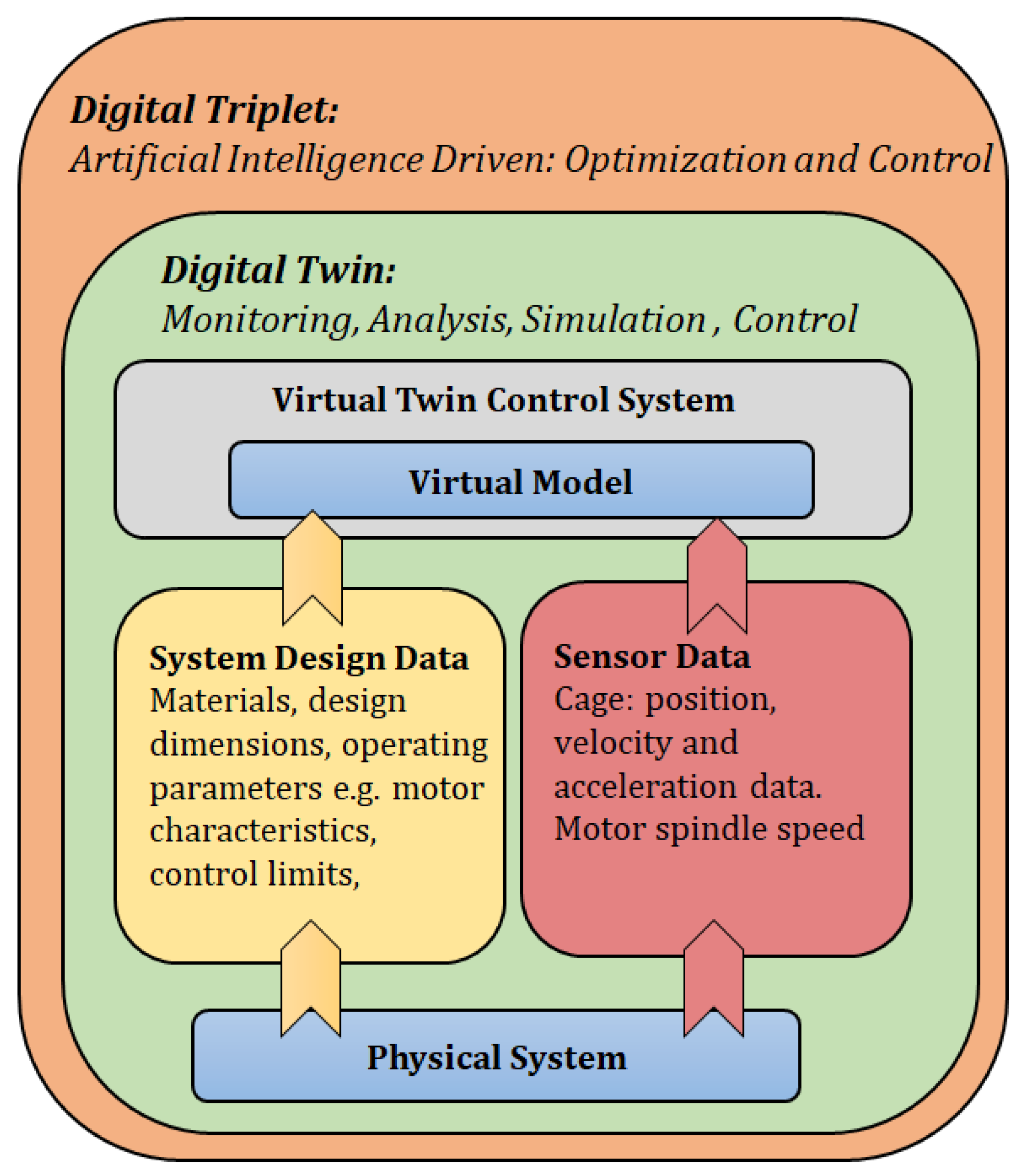
2.1.2. Digital Triplet

The Digital Triplet concept was developed by Umeda et al. [6] in order to tackle two key problems in the Japanese manufacturing industry;
i.
The adoption of digitisation in Japanese manufacturing industries might not fit the prevailing Japanese engineering philosophy and might extinguish its strengths.
ii.
Engineers/technicians found it difficult to adopt digitisation due to the need to apply their knowledge and experience to effect changes not only to the physical system but also to their virtual counterparts.
The key observation was that traditionally, system improvements were applied directly to the physical manufacturing systems but there was a need to execute such activities by utilising both virtual and physical worlds. The solution involved the integration of physical, virtual and intelligent activity worlds resulting in the development of the Digital Triplet concept. As illustrated in Figure 2, the Digital Triplet has an additional intelligent activity layer on top of the typical Digital Twin design. This additional layer represents the analysis, decision making and improvement execution done by engineers/technicians, guided by years of acquired knowledge and experience [6].
Digital Triplet was developed as a concept and provides a rich area of exploration through research into possible implementation methods and their applications. An example of such an implementation strategy involves the use of machine learning modules in the intelligent activity layer and uses machine to machine communication to form the necessary interconnection between the layers. Machine learning is a key contributor to the achievement of Industrie 4.0 agenda and has a growing body of research with a wide variety of applications in industry [6].

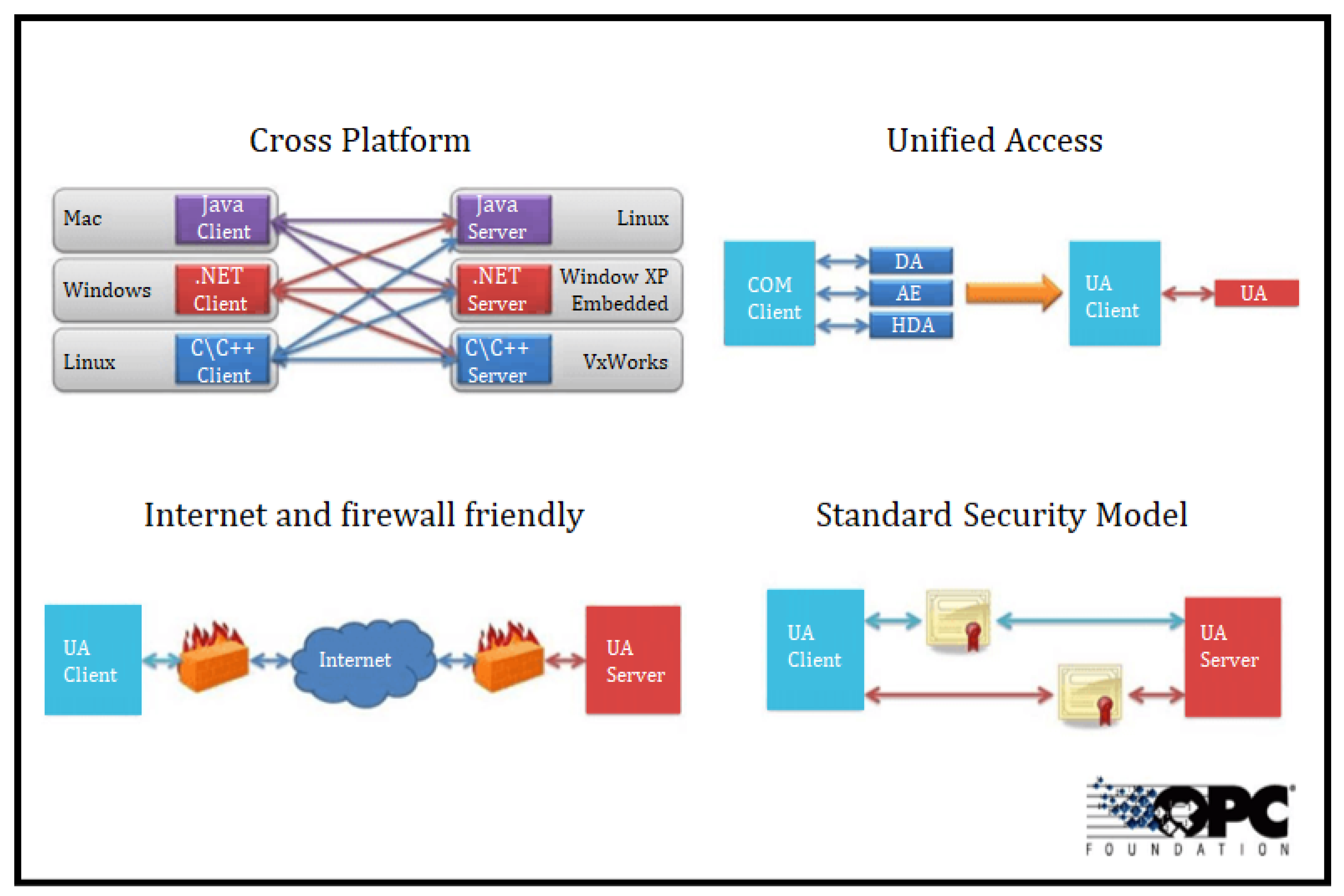
2.2. OPC-UA in Industrie 4.0

Open Platform Communication (OPC) is a communication protocol that enables secure and reliable exchange of data between industrial hardware devices. It contains a series of specifications that define the interface of Clients and Servers, as well as between Servers [11]. OPC Data Access was the first OPC Classic specification released in August 1996 with the first revision occurring in 1997. The standard quickly received support from commercial products leading to it being adopted as the industrial standard [12,13].
During its early adoption phase, the OPC protocol encountered several challenges which included:
i.
Restricted use to only Windows operating system;
ii.
Difficulty in handling and integrating different OPC services, i.e.OPC-AE, OPC-DA, OPC-HDA;
iii.
Incompatibilities with internet firewalls protocols;
iv.
Emergent security issues since initially access and data security was not a concern.
To address these limitations, the OPC Foundation reworked the standard specifications in order to future proof the protocol and unify different address spaces. This resulted in the development of Open Platform Communication-Unified Architecture (OPC-UA). This new protocol allows access to other specifications and ensures secure data exchange between server–server and client–server communications links. It provides a layer of interoperability, which enables communication regardless of the native operating system [13,14]. Figure 3 highlights the key areas of limitation addressed by the OPC-UA protocol.
An OPC-UA server also has the capability of running local functions that can be written to perform tasks such as data processing. With this capability, it was possible to embed machine learning modules within the UA server to aid in analysis and decision-making tasks thus achieving intelligent world activities [13].

2.3. Integration of Machine learning in Digital Twins and OPC-UA

Generally, artificial intelligence (AI) and machine learning (ML) techniques have been used to perform various tasks in line with Industrie 4.0, including, but not limited to, predictive maintenance, health monitoring, fault diagnosis, adaptive control and operation process optimisation. Integration of such features into the Digital Twin technology has been explored in various manufacturing scenarios, as demonstrated by [15,16,17,18]. The integration of both AI and ML with Digital Twin technology is beneficial in enhancing the interaction between the virtual and physical entity so that processes and operations can be analysed, predicted and optimised. This is achievable since Digital Twin technology not only emphasises the importance of simulation in virtual space but also allows the interaction and execution of intelligent activities between physical and virtual spaces during system operation [17,18].
Artificial intelligence and machine learning requires standardised access to data sources, which it analyses to gain insight into systems. OPC-UA technology comes in handy in addressing this need as it enables a platform-independent interoperability standard for moving data between systems and devices in operation. Intelligent services can utilise data to optimise operations or perform predictive maintenance only if the right levels and standards of connectivity are met [19].

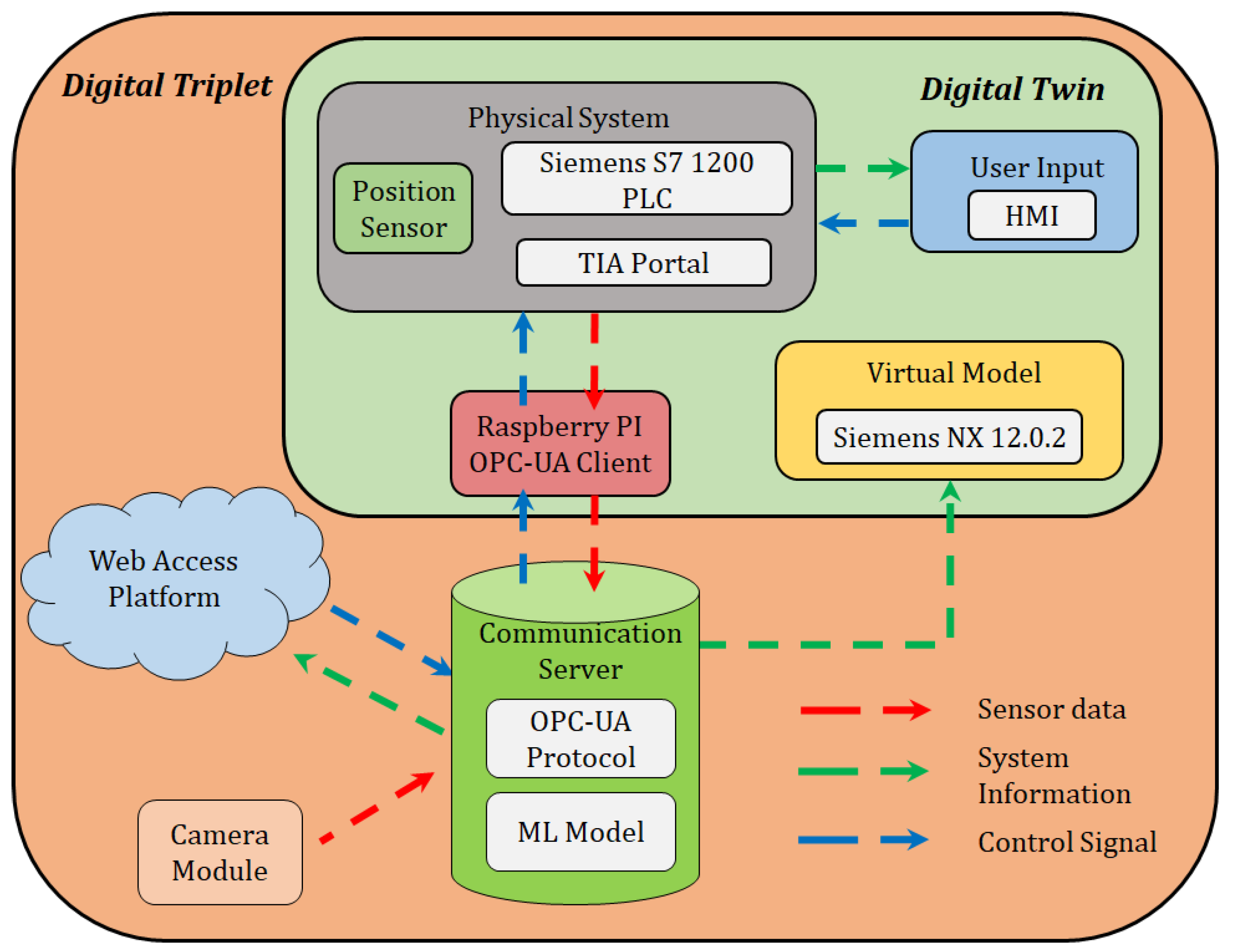
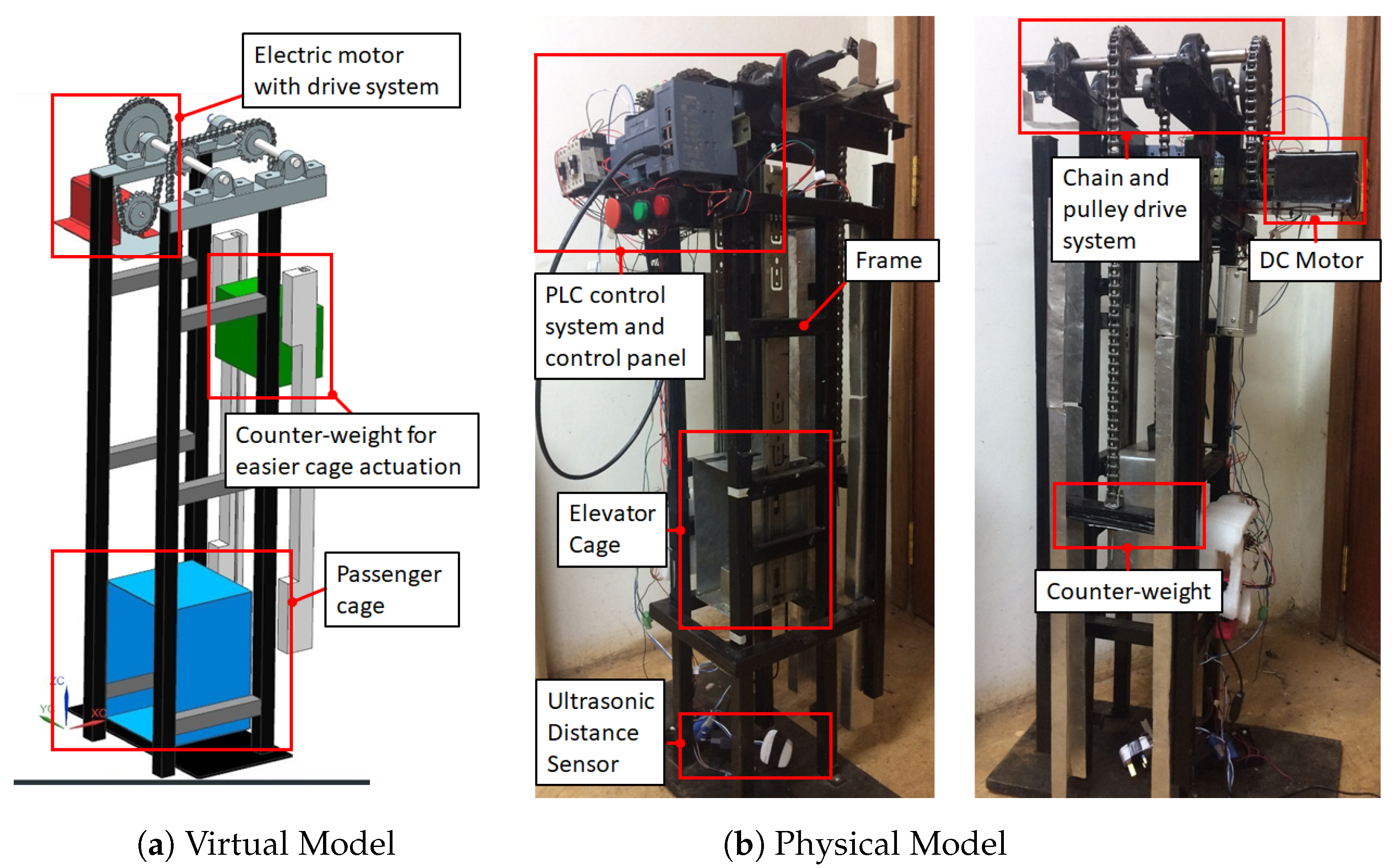
3. Design of the Digital Triplet for the Three-Floor Model Elevator System

This research aimed at offering a holistic monitoring method that can be applied to most if not all elevator systems modelled using the block diagram shown in Figure 4. It began by creating a virtual duplicate of a model elevator system, which was linked to its physical counterpart and provided real-time status information of the system. By utilising the advanced features of OPC-UA protocol, communication and data exchange between the UA clients was achieved. In addition, an object detection module was embedded within the server to analyse image data received from a camera. Through this module, harmful objects were detected and action was taken to halt elevator motion. The incorporated of the camera-based system and machine learning module improves the functionality of the Digital Twin and converted it into a Digital Triplet.
The implementation of a Digital Triplet for a physical system involves the representation of a physical system in cyberspace using a virtual Model for simulation, monitoring and control with the application of artificial intelligence for increased system functionality. Figure 5 shows the component and interaction layout followed during the implementation of the project. The key elements of the system include:
i.
Physical System—Consisted of the three-floor elevator model controlled by a Siemens S7 1200 PLC, an ultrasonic distance sensor and an HMI;
ii.
Virtual Model—A digital model of the elevator system was generated using Siemens NX 12.0.2 modelling and simulation software. It receives sensor data from the Raspberry Pi and updates the position of the model in line with the position of the elevator cage;
iii.
Raspberry Pi—This served as an OPC-UA client and acted as an intermediary between the PLC and OPC server since PLC S7-1200 cannot function independently as an OPC-UA Client;
iv.
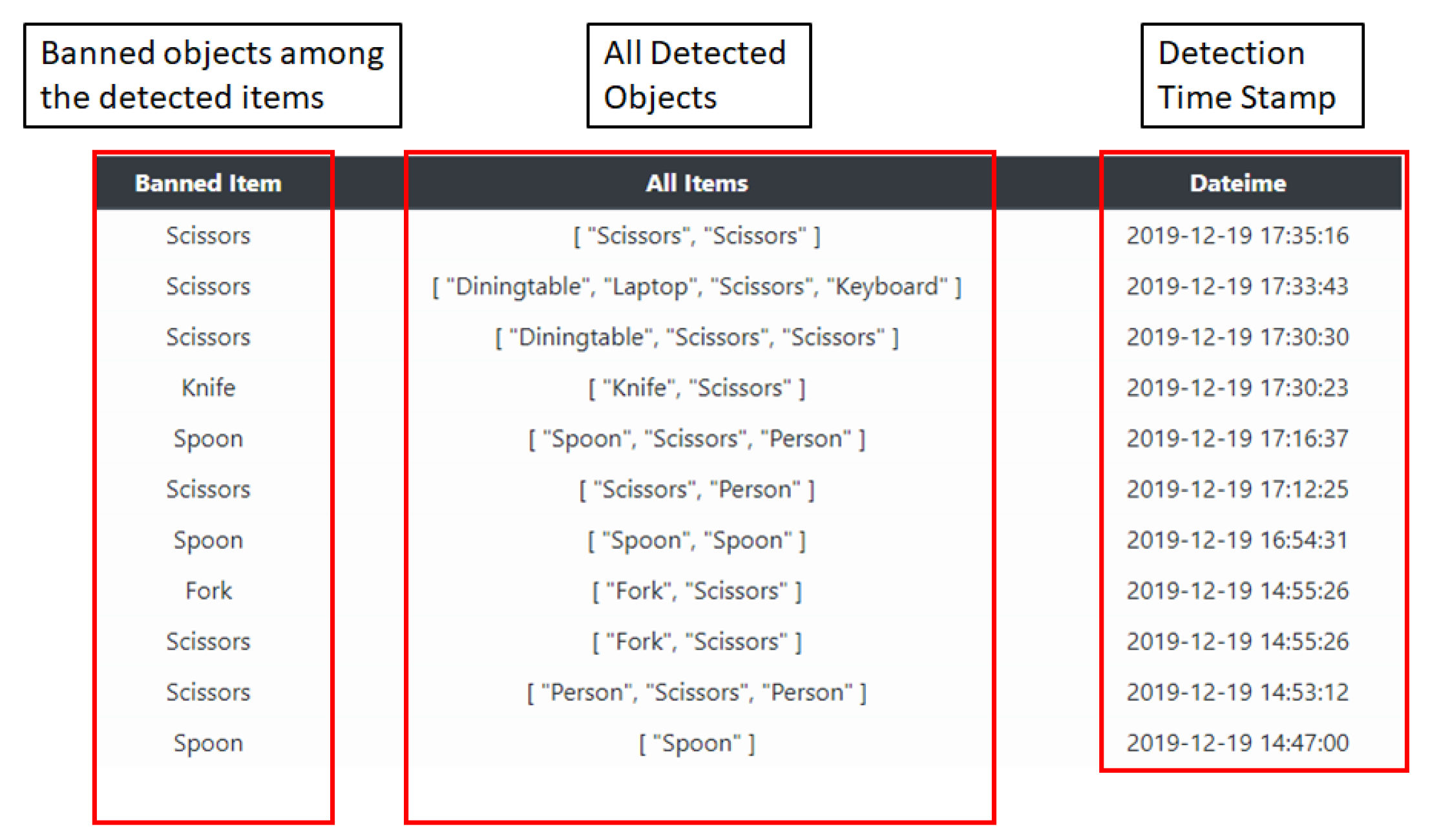
OPC Communication Server—An information server that enabled communication between the physical system and the web access platform. It also contained a trained object recognition module able to detect objects from a camera feed;
v.
Web Access Platform—An internet enabled means of controlling and monitoring the elevator model remotely;
vi.
Camera—A security feature, akin to common surveillance systems in elevators with a connection to the OPC server. Image frames from the camera are captured and sent to the object recognition algorithm housed in the OPC server.

3.1. Virtual and Physical Model Implementation

The initial step to the implementation process was designing all the required model elevator subsystems, for example; metal frame, drive pulley mechanism, counter weight and rails, in CAD software, i.e., Siemens NX 12.0.2, as shown in Figure 6a. Apart from CAD functionality, Siemens NX has the Mechatronic Concept Designer (MCD) feature that enables the definition of system physical properties. Once the physical design was complete, fabrication was done with the results, as shown in Figure 6b. The physical system was controlled using a Siemens PLC S7 1200 with the primary actuator being a 12 V DC motor that ran the movement of the passenger cage between floors. The system was then programmed using Siemens TIA portal to operate as a typical three-floor lift operable from a Siemens HMI or from a web-based access system.
Siemens PLC S7 1200 can not be used as an OPC-UA client and thus an intermediary device, in this case a Raspberry Pi, was used to act as the OPC-UA client, communication with the Server and relay this information to the PLC. In addition, the Raspberry Pi also read the ultrasonic sensor data and wrote this value directly to the Server and relayed it also to the virtual model.

3.1.1. OPC Server and Object Recognition Module

The OPC Server facilitated communication between the various elements of the system and acted as a central data source for all the UA client devices. It also could call functions that act on the collected data and process it to useful information. In this research, the object recognition model was defined as a series of functions that run within the OPC Server. The model was based on the YOLOV3 framework and was trained using the Common Objects in Context (COCO) image-set.
The system camera was configured as an OPC client and was able to forward captured image frames to the OPC Server. Once received, an image was pre-processed and fed through the object detection model for object detection and classification. Based on the results from this process, two key variables, i.e., detected objects (array) and system disable (boolean), were updated and stored on the UA server. These variables along with others within the server were queried by UA clients and the information read from the Server.
The YOLOV3 model was trained and three image categories, i.e., knife, fork and spoon, were selected to represent harmful materials that should not be allowed into the elevator system. When any of the three were detected, an alert event was triggered and sent from the OPC-UA server to the PLC and web access platform.

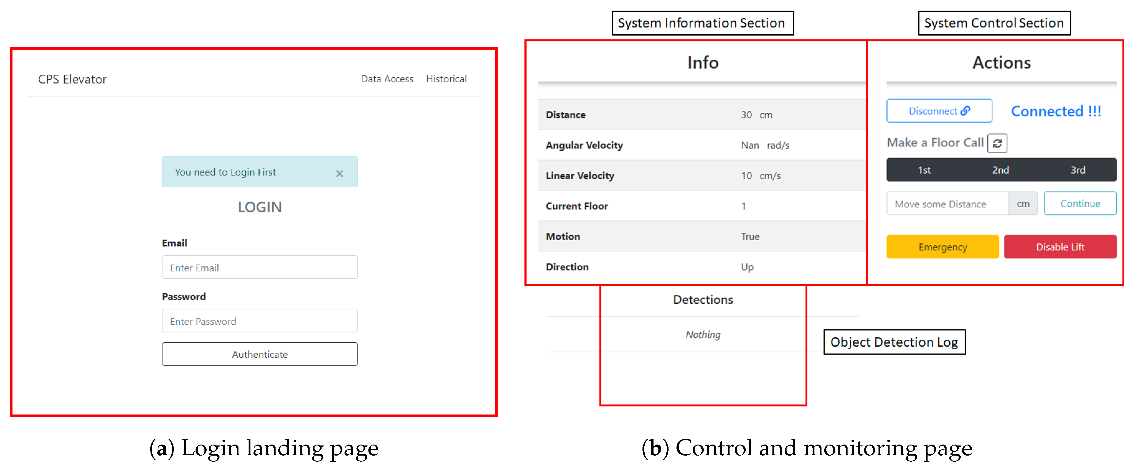
3.1.2. Web Access Platform (WAP)

A web access platform (WAP) was created using Python programming language to enable remote access and control of the elevator. MongoDB was used to implement the data storage system. The web interface was configured as a UA client and hence able to read data variables directly from the server and updates the user dashboards. The WAP features a login section to ensure secure access control to unauthorised users, as shown in Figure 7a. Once login credentials have been authenticated, the user is presented with the control dashboard, as shown in Figure 7b.
The dashboard gives the user relevant information concerning the status of the elevator, i.e., its current location, speed and direction. The user also has access to the direct camera feed and can monitor the ongoings in the elevator. The user can perform floor calls, which commands the elevator to move to a desired floor, and precision floor control can be performed by specifying an exact amount of distance for the elevator cage to move. Additionally, there are emergency and lift disable options that can be used in the event of an emergency. The system also keeps a log, based on objects detected by the object detection system; thus, a user can see any banned items that have been detected by the system with their relevant time stamp, as shown in Figure 8.

3.2. Elevator Control Sequence

The operation of the elevator system started by powering the PLC control system and ensuring connectivity with the OPC-UA server. The elevator was controlled on-site through the HMI or remotely via the WAP. If a floor call was activated, the elevator moves to the required floor while updating the the UA server. During operation, the camera sent image frames to the server for object recognition. The detection module updated variables within the UA server, which the UA client could query. If a banned item was detected, an alert was sent to the WAP and PLC for the lift to halt.

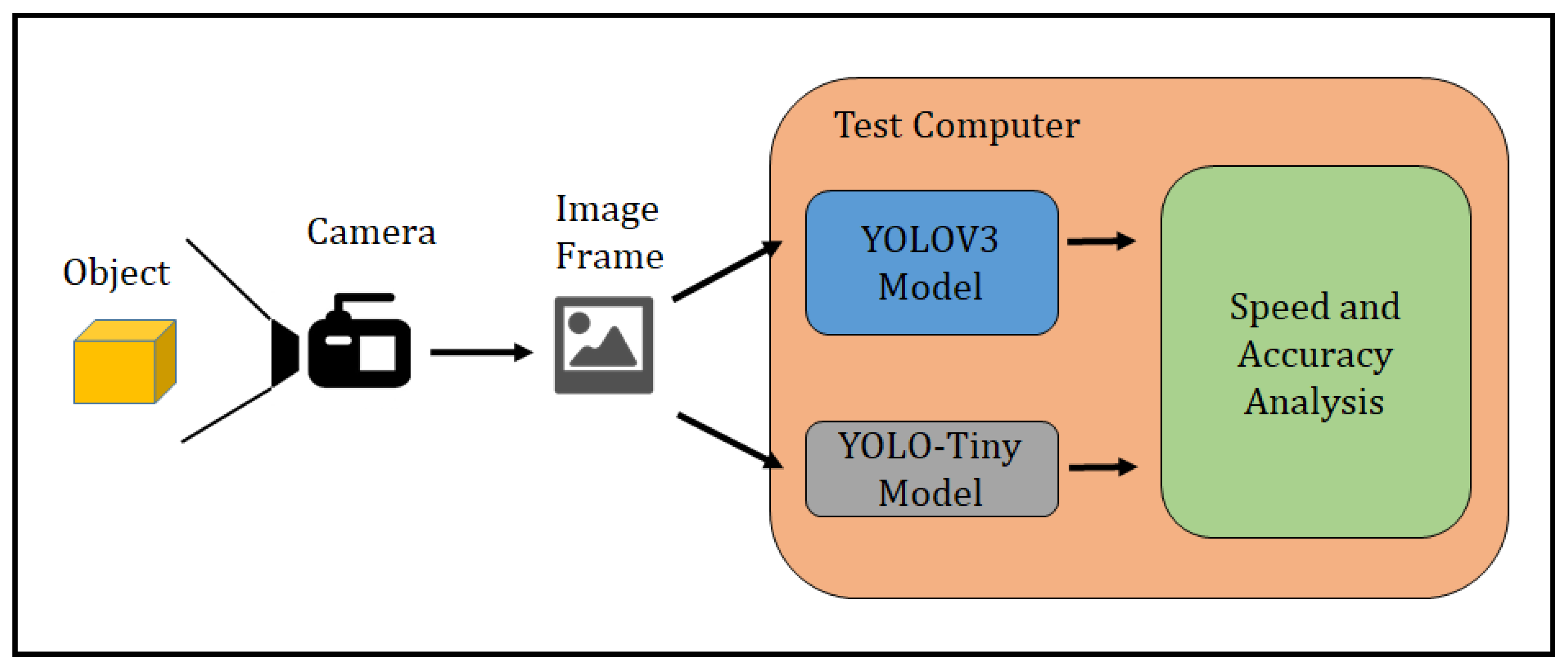
4. Performance Testing: Preliminary Accuracy and Speed Testing of Object Detection Models

Before selecting the type of object recognition model to implement, the speed and accuracy of two candidate models were tested. These models were a YOLOV3 model trained on the full COCO data set and a custom model based on the YOLO-Tiny and only trained on two object categories. The objective of the experiment was to determine the extent to which a reduction in model size would impact the model speed and accuracy.

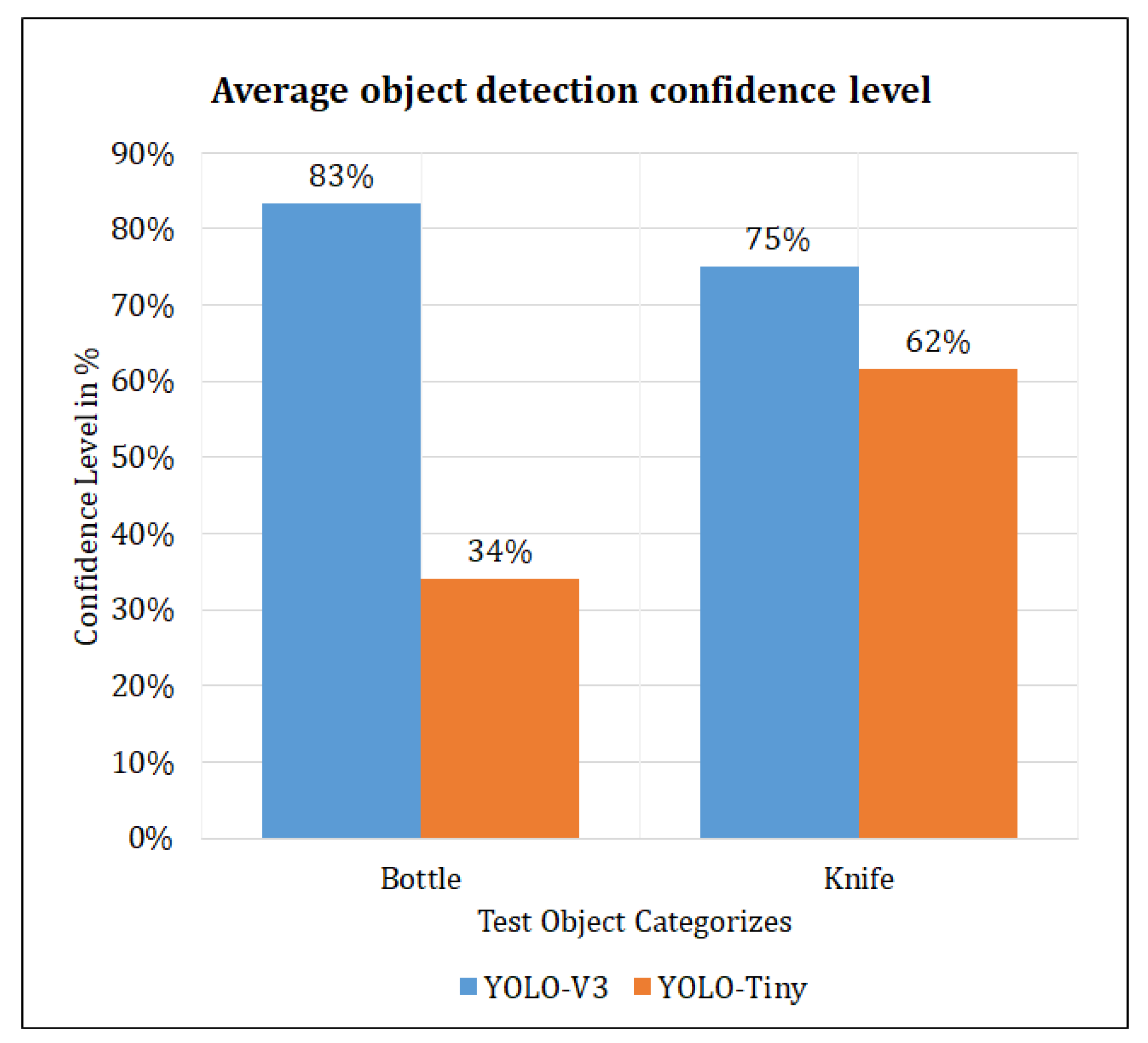
4.1. Model Accuracy and Speed Experiment

To determine the accuracy and speed of the two candidate models; YOLOV3 and YOLO-Tiny, an experiment set-up was done, as shown in Figure 9. A camera was connected to the host computer and was positioned in view of the test object. Thirty experiment runs were performed where the image in front of the camera changed between a bottle and a knife. This image was then captured and sent to the two candidate models for recognition. The model confidence levels and processing time were recorded.
The results of the accuracy-speed experiment are shown in Table Table 1. Figure 10 shows the plot of the average confidence level achieved by YOLOV3 and YOLO-Tiny models. YOLOV3 had an average confidence level of 83.34 % (bottle) and 75.13 % (knife) while YOLO-Tiny had an average of 34 % (bottle) and 61.56 % (knife). From the experiment data, YOLOV3 demonstrated a high confidence level in its detections and thus is more accurate as compared to the YOLO-Tiny model.
From the experiment results, YOLOV3 had an average processing time of 1.2173 s, while YOLO-Tiny had an average processing time of 0.1252 s. From these results, the YOLO-Tiny model had a lower processing time than YOLOV3. This high speed was achieved with the sacrifice of accuracy. Based on the focus of the end application, high accuracy or fast speed, the appropriate model can be selected. Due to the focus on security enhancement, which relies on high accuracy, a key motivation in this research, the final implementation was done using the YOLOV3 model.

4.2. System Interstitial Time Experiments

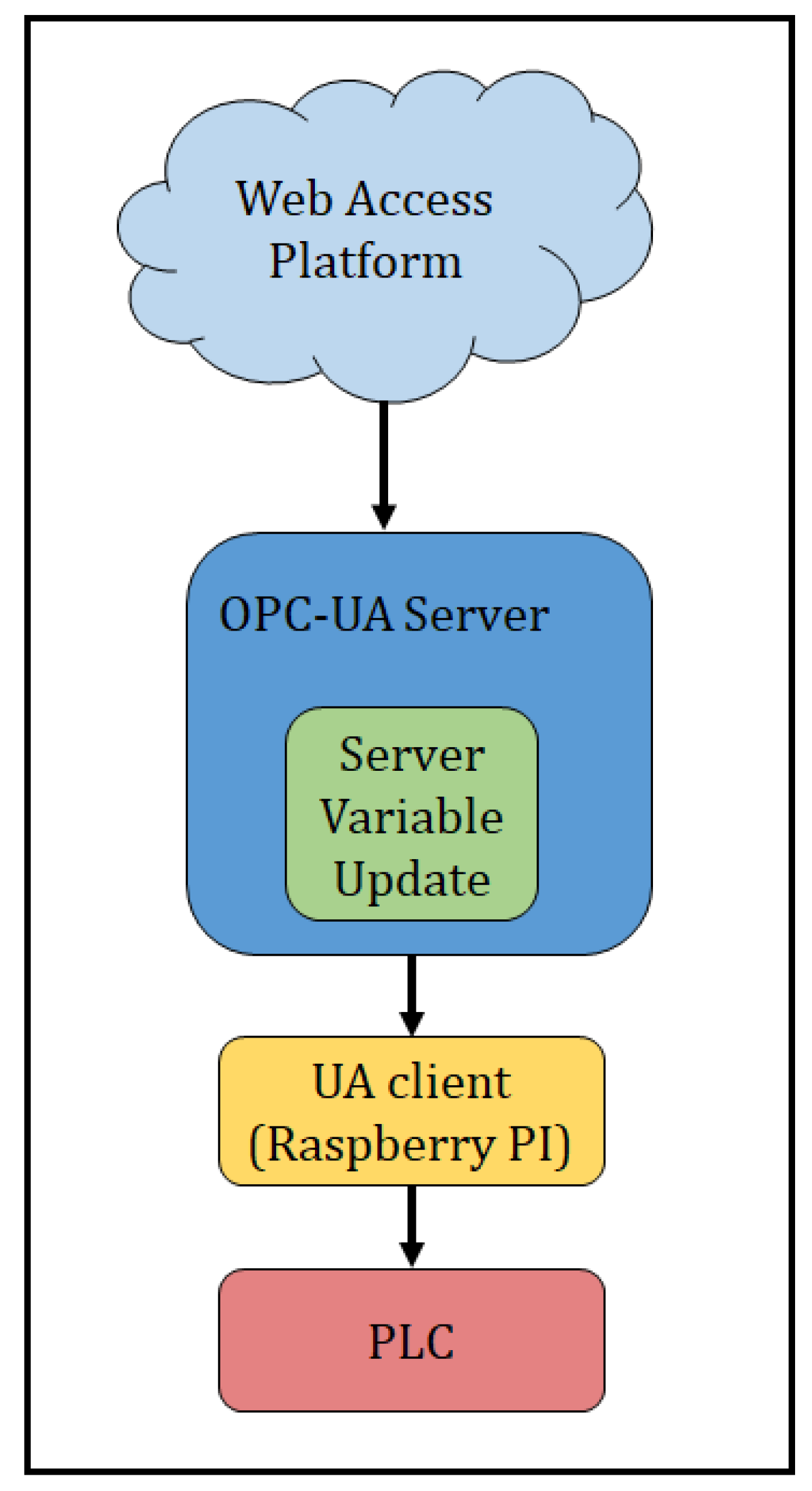
4.2.1. Time Response between WAP and PLC Experiment

The main aim of this experiment was to establish the signal travel time between the web access platform and the PLC. The experiment results gave information about the general real-time performance of the system and provided a based-line time value from which further comparisons and optimisation of the system could be done.The experiment set-up was as shown in Figure 11, and a total of seventy experiment runts were performed. A single signal passes through the system consisting of four main sub-processes;
i.
Sending of user command from WAP to OPC-UA server;
ii.
Update of relevant variables within the OPC-UA server;
iii.
Query and update of server variable by UA client (Raspberry Pi);
iv.
Relay of variable from UA client to PLC.
The results from this experiment showed an average response time of 0.246 s. This was in line with similar timing experiment conducted from previous research [20], although it should be noted that the system design and component configuration from Osinde et al., was considerably different from that used in this paper and thus direct time value comparisons are not valid.

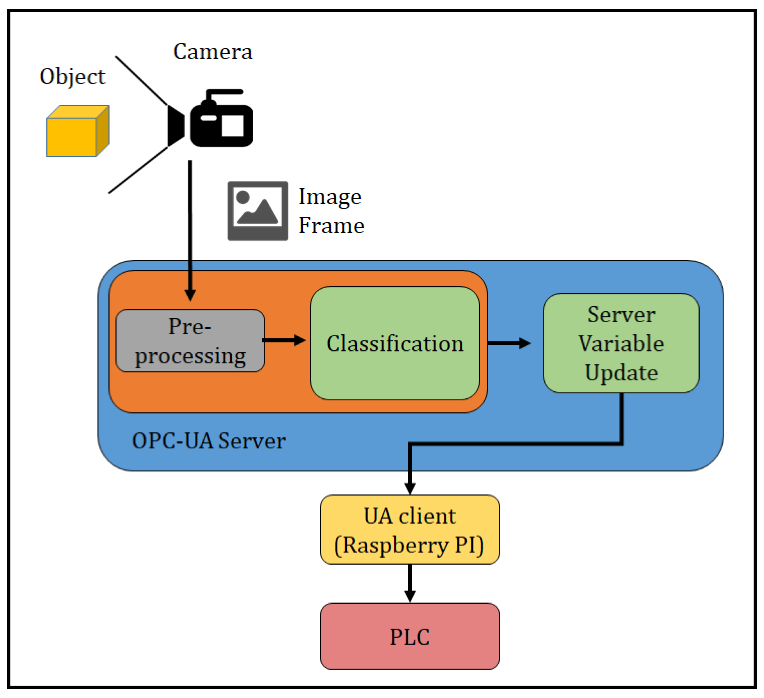
4.2.2. Time Response between Camera, ML Model and PLC Experiment

The time taken from camera frame capture to PLC actuation, i.e., total signal travel time is an important measure of system performance. By minimising this period, the system can get as close to real time operation as possible. To perform the optimisation, the time contribution by the different sub-processes involved need to be determined. This was done through experimentation and the experiment set-up was as shown in Figure 12. A single signal pass through the system consists of six main sub-processes;
i.
Sending of camera frame;
ii.
Pre-processing of frame to be fed into the YOLOV3 model;
iii.
Classification of object within frame;
iv.
Update of relevant variables within the OPC-UA server;
v.
Query and update of server variable by UA client (Raspberry Pi);
vi.
Relay of variable from UA client to PLC.
During the experiment, different objects were placed in front of the camera as shown. A picture frame was sent to the OPC-UA server for recognition by the object detection model. Once detection was complete, the necessary server variables were updated. The UA client then queried these variables and relayed the changes to the PLC for actuation. This was repeated for fifty experiment runs. The average from the experiment runs are shown in Table 2. The average overall signal travel time was observed as 1.338 s. From the result shown in Table 2, it can be observed that the major contribution to the total signal time was the model classification time with an average of 1.026 s. The system performed as expected as this result is similar to that obtained by the YOLOV3 model in the previous experiment.

5. Conclusions

As Digital Twin technology and the OPC-UA communication protocol gain increased adoption into mainstream manufacturing industries, their integration with artificial intelligence and machine learning techniques has led to the development of the Digital Triplet. In this paper, a real time monitoring and control system for a model three-floor elevator system was demonstrated using the Digital Triplet method. The physical system was fabricated and linked to its virtual model via OPC-UA communication protocol. An object detection algorithm was implemented, capable of detecting harmful objects while the elevator was under operation. A web access platform was also designed, which allowed remote monitoring and control. The performance of two candidate object detection model designs YOLOV3 and YOLO-Tiny was investigated by looking at the accuracy and speed of both models when subject to the same data set. On average, YOLOV3 was slower than YOLO-Tiny, taking around 1.217 s compared to 0.125 s, when performing object classification tasks. However, this was achieved with an average drop in accuracy, with YOLOV3 having an average of a 79.21% confidence level versus YOLO-Tiny with a 47.75% confidence level. YOLOV3 was selected based on its high accuracy and implemented in the Digital Triplet. A second experiment was conducted to determine the total signal travel time from camera frame capture to PLC actuation. The aim of this experiment was to investigate the time contribution of the various sub-processes involved. The machine learning module had the highest contribution with an average of 1.026 s out of a total signal travel time of 1.338 s. Future research is geared to improving the object detection processing time without significantly affecting the detection confidence level to enable the system to run as close as possible to real-time with high accuracy.

Author Contributions

Conceptualization, M.M.G., J.B.B. and A.K.C.; data curation, M.M.G., A.K.C. and R.K.L.; formal analysis, M.M.G.; funding acquisition, J.B.B.; investigation, M.M.G. and A.K.C.; methodology, A.K.C. and P.M.N.; project administration, J.B.B., P.M.N. and H.S.; software, A.K.C. and C.W.K.; validation, J.B. and H.S.; visualization, M.M.G., R.K.L. and C.W.K.; writing—original draft, M.M.G., and R.K.L.; writing—review and editing, M.M.G., R.K.L. and C.W.K. All authors have read and agreed to the published version of the manuscript.

Funding

This research received no external funding.

Acknowledgments

This research was carried out at Dedan Kimathi University of Technology(DeKUT) - Kenya, Mechatronic laboratory which offered the equipment required to carry out this research.

Conflicts of Interest

The authors declare no conflict of interest.

References

  1. Neugebauer, R.; Hippmann, S.; Leis, M.; Lherr, M. Industrie 4.0-From the perspective of applied research. In Proceedings of the 49th CIRP-CMS 2016, Stuttgart, Germany, 25–27 May 2016; pp. 2–7. [Google Scholar]
  2. Mrugalska, B.; Wyrwicka, M. Towards lean production in industry 4.0. Procedia Eng. 2017, 182, 466–473. [Google Scholar] [CrossRef]
  3. Tao, F.; Cheng, J.; Qi, Q.; Zhang, M.; Zhang, H.; Sui, F. Digital twin-driven product design, manufacturing and service with big data. Int. J. Adv. Manuf. Technol. 2018, 94, 363–369. [Google Scholar] [CrossRef]
  4. Kritzinger, W.; Karner, M.; Traar, G.; Henjes, J.; Sihn, W. Digital Twin in manufacturing: A categorical literature review and classification. IFAC PapersOnLine 2018, 51, 1016–1022. [Google Scholar] [CrossRef]
  5. Diez-Olivan, A.; Del Ser, J.; Galar, D.; Sierra, B. Data fusion and machine learning for industrial prognosis: Trends and perspectives towards Industry 4.0. Inf. Fusion 2019, 50, 92–111. [Google Scholar] [CrossRef]
  6. Umeda, Y.; Ota, J.; Kojima, F.; Saito, M.; Matsuzawa, H.; Sukekawa, T.; Takeuchi, A.; Makida, K.; Shirafuji, S. Development of an education program for digital manufacturing system engineers based on ‘Digital Triplet’concept. Procedia Manuf. 2019, 31, 3563–3576. [Google Scholar]
  7. Uhlemann, T.; Lehmann, C.; Steinhilper, R. The Digital Twin: Realizing the Cyber-Physical Production System for Industry 4.0. In Proceedings of the 24th CIRP Conference on Life Cycle Engineering, Kamakura, Japan, 8–10 March 2017; pp. 335–340. [Google Scholar]
  8. Negri, E.; Fumagall, L.; Macchi, M. A review of the roles of Digital Twin in CPS-based production systems. Procedia Manuf. 2017, 11, 939–948. [Google Scholar] [CrossRef]
  9. Um, J.; Weyer, S.; Quint, F. Plug-and-Simulate with Modular Assembly Line enabled by Digital Twins and the use of AutomationML. IFAC PapersOnLine 2017, 50, 15904–15909. [Google Scholar] [CrossRef]
  10. Weyer, S.; Meyer, T.; Ohmer, M.; Gorecky, D.; Zuhlke, D. Future Modeling and Simulation of CPS-based Factories and Example from the Automotive Industry. IFAC PapersOnLine 2016, 49, 97–102. [Google Scholar] [CrossRef]
  11. OPC Foundation. “What is OPC?”. Available online: https://opcfoundation.org/about/what-is-opc/ (accessed on 17 March 2020).
  12. Silva, M. “OPC UA support for Beremiz softPLC”. Available online: https://hdl.handle.net/10216/115498 (accessed on 17 March 2020).
  13. OPC Foundation. “History - OPC Foundation”. Available online: https://opcfoundation.org/about/opc-foundation/history/ (accessed on 20 March 2020).
  14. Schwarz, M.; Borcsok, J. A survey on OPC and OPC-UA: About the standard, developments and investigations. In Proceedings of the 2013 XXIV International Conference on Information, Communication and Automation Technologies (ICAT), Sarajevo, Bosnia and Herzegovina, 30 October–1 November 2013. [Google Scholar]
  15. Soderberg, R.; Warmefjord, K.; Carlson, J.; Lindkvist, L. Toward a Digital twin for real-time geometry assurance in individualized production: 360 Degree Comparison. CIRP Ann. 2017, 66, 137–140. [Google Scholar] [CrossRef]
  16. Bao, J.; Guo, D.; Li, J.; Zhang, J. The modelling and operations for the digital twin in the context of manufacturing. Enterp. Inf. Syst. 2018, 13, 534–556. [Google Scholar]
  17. Qi, Q.; Tao, F. Digital Twin and Big Data Towards Smart Manufacturing and Industry 4.0. IEEE Access 2018, 6, 3585–3593. [Google Scholar] [CrossRef]
  18. Tao, F.; Zhang, M. Digital Twin Shop-Floor: A New Shop-Floor Paradigm Towards Smart Manufacturing. IEEE Access 2017, 5, 20418–20427. [Google Scholar] [CrossRef]
  19. Luo, W.; Hu, T.; Zhu, W.; Tao, F. Digital twin modelling method for CNC machine tool. In Proceedings of the 2018 IEEE 15th International Conference on Networking, Sensing and Control (ICNSC), Zhuhai, China, 27–29 March 2018. [Google Scholar]
  20. Osinde, N.; Byiringiro, J.; Gichane, M.; Smajic, H. Process Modelling of Geothermal Drilling System Using Digital Twin for Real-Time Monitoring and Control. Designs 2019, 3, 45. [Google Scholar] [CrossRef] [Green Version]
Figure 1. Illustration of the evolution from Digital Model and Digital Shadow to Digital Twin [4].
Designs 04 00009 g001
Figure 2. Original Digital Triplet concept [6].
Designs 04 00009 g002
Figure 3. Key features and benefits of the Open Platform Communication-Unified Architecture (OPC-UA) protocol [11].
Designs 04 00009 g003
Figure 4. Block diagram of the key components and interactions of a typical Digital Triplet system.
Designs 04 00009 g004
Figure 5. Block diagram of Digital Triplet system design.
Designs 04 00009 g005
Figure 6. Implementation of virtual and physical models.
Designs 04 00009 g006
Figure 7. Web access platform.
Designs 04 00009 g007
Figure 8. Detected objects log page.
Designs 04 00009 g008
Figure 9. YOLOV3 and YOLO-Tiny accuracy-speed experiment set-up.
Designs 04 00009 g009
Figure 10. Comparison plot of average confidence level for object detection models.
Designs 04 00009 g010
Figure 11. Web Access Platform (WAP) to Programmable Logic Controller (PLC) signal travel time experiment set-up.
Designs 04 00009 g011
Figure 12. Camera to PLC through machine learning (ML) module signal travel time experiment set-up.
Designs 04 00009 g012
Table 1. Model accuracy and speed comparison experiment results.
Pretrained Model-
YOLOV3 (COCO Dataset)
Trained Model-YOLO Tiny
(Custom Dataset)
No.BottleKnifeTimeBottleKnifeTime
1 0.5630781.436954 0.5381340.293176
2 0.5185051.097018 0.268740.115766
3 0.7126441.147794 0.2386050.122837
40.604001 1.1156720.35785 0.11534
50.617293 1.0958990.236708 0.11451
60.768312 1.0983820.20796 0.118993
70.847213 1.0874840.299728 0.115685
80.83869 1.1016910.246914 0.117492
90.461898 1.0852790.202363 0.114799
100.878751 1.0861990.222235 0.114908
110.855653 1.0855880.38596 0.115583
120.67897 1.0890470.267305 0.120144
13 0.4310091.236007 0.3521580.12096
14 0.621661.235347 0.3948330.121908
15 0.9777591.227963 0.9239650.115066
16 0.9828021.251054 0.7173960.122392
17 0.9431871.232909 0.8770830.115504
18 0.8883421.236449 0.7571180.117676
19 0.9458461.489872 0.9745520.113529
20 0.6794641.338581 0.7288010.124169
210.932162 1.265070.411357 0.120918
220.950707 1.2784510.239319 0.11672
230.988292 1.3222830.208433 0.11777
240.995962 1.218620.523656 0.119485
250.999116 1.2227930.365052 0.122549
260.999661 1.2162170.834931 0.115162
270.996282 1.2225530.654359 0.119391
280.457893 1.2178950.342688 0.150091
290.984947 1.5765050.24305 0.115937
300.978729 1.2030160.208724 0.128472
AVG0.8333960.75131.2172860.3399260.6155810.125231
Table 2. Table of average signal travel time experiment results.
Camera
Frame
Send Time
Frame Pre-
Processing
Time
Model
Classification
Time
Variable
Update
Time
Raspberry Pi
Response
Time
Raspberry
Pi to PLC
Write Time
Total
Signal
Travel Time
Average time in Sec0.0250.0031.0260.0500.2020.0331.338099

