The Design of a Thermoelectric Generator and Its Medical Applications

 , ,
, ,  and
and
Abstract
:1. Introduction
- High reliability with no moving parts; maintenance-free
- Wide range of power generation (kW–µW)
- Noiseless operation
- Compact size and can be embedded in an existing setup
- Direct energy conversion without any intermediate form of energy conversion.
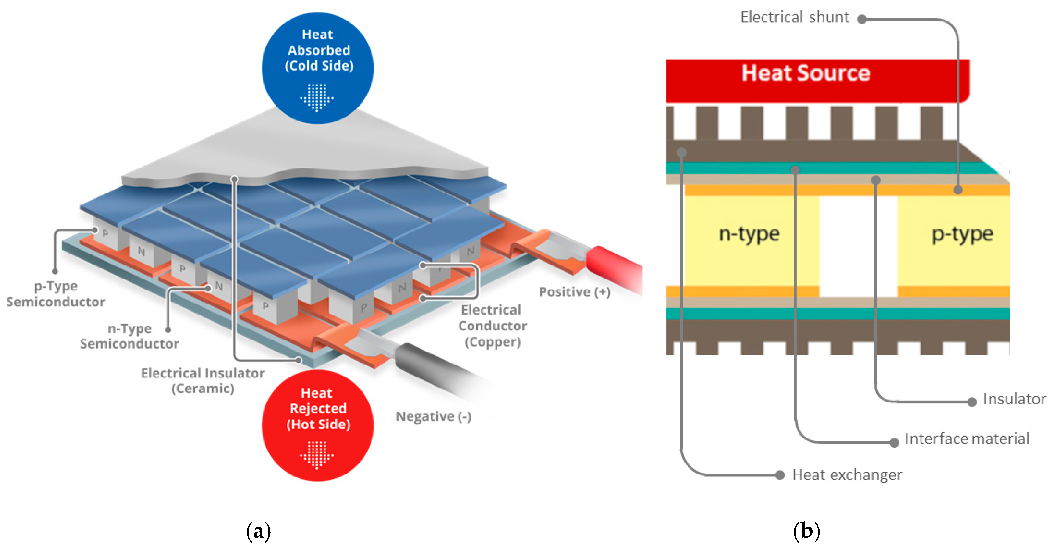
2. Working Principle of Thermoelectric Devices
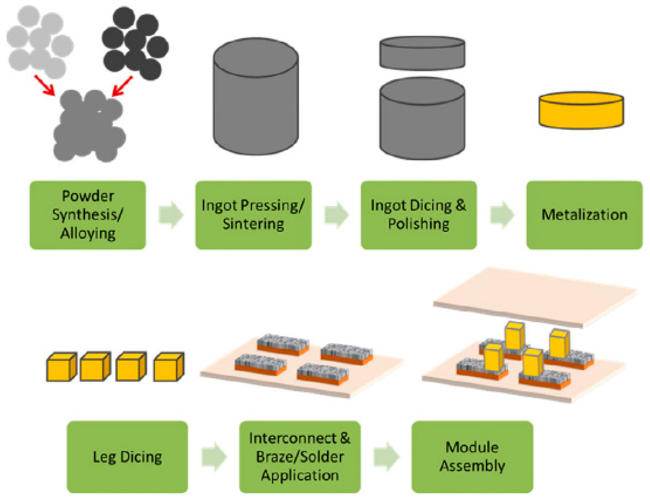
3. Materials and Manufacturing Process of TEG
Manufacturing of Thermoelectric Materials
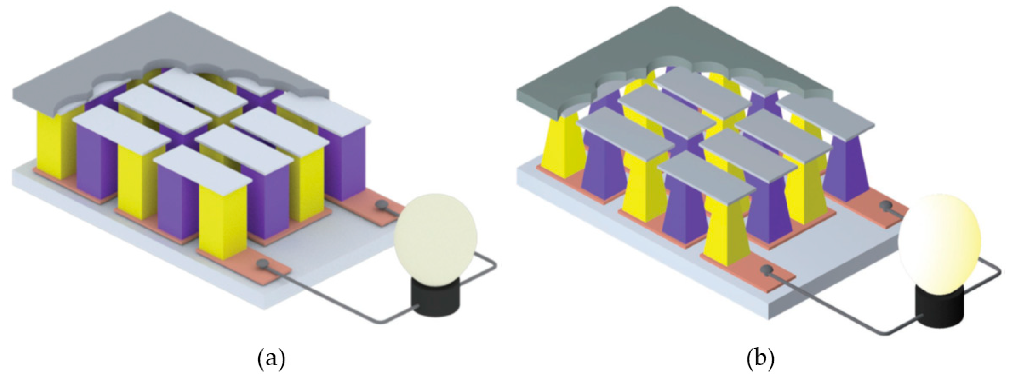
4. Architecture of Thermoelectric Generators
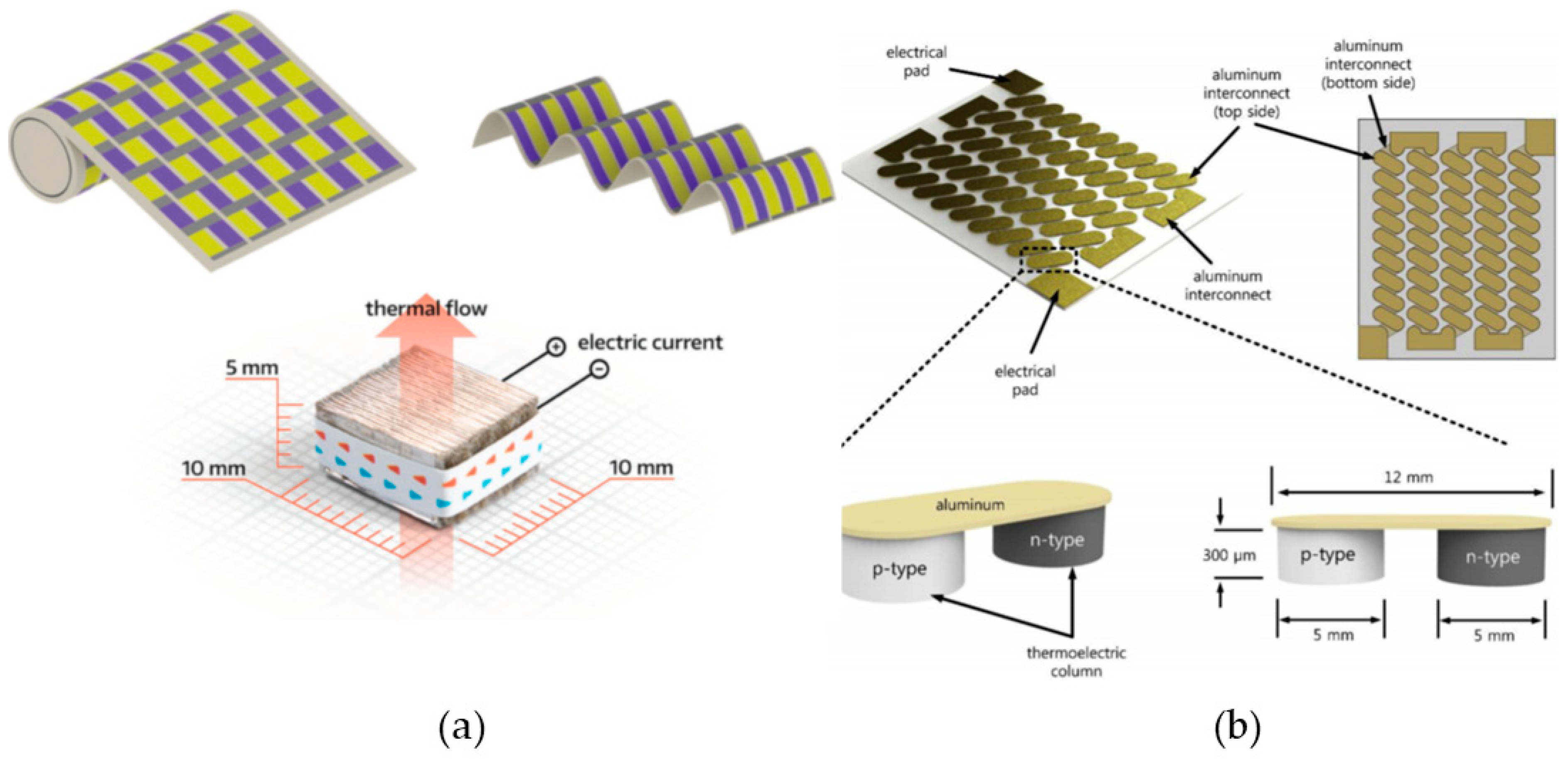
4.1. Flexible TEGs
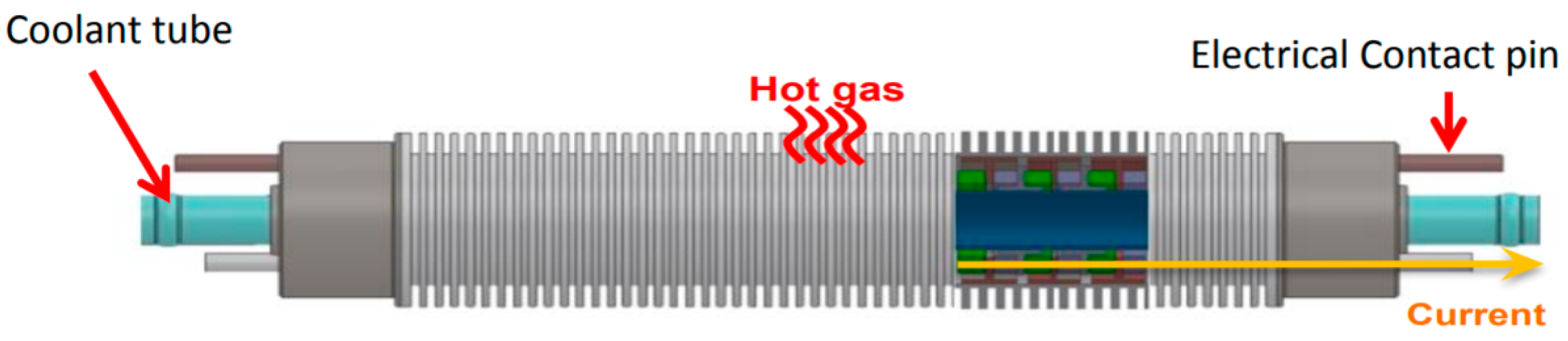
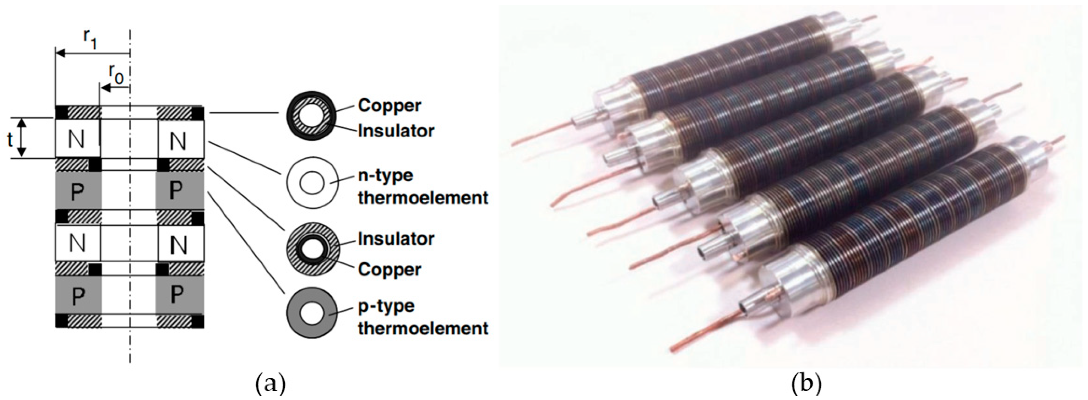
4.2. Cylindrical Bulk TEG
4.3. Flat Bulk TEG
4.4. Thin-Film TEG
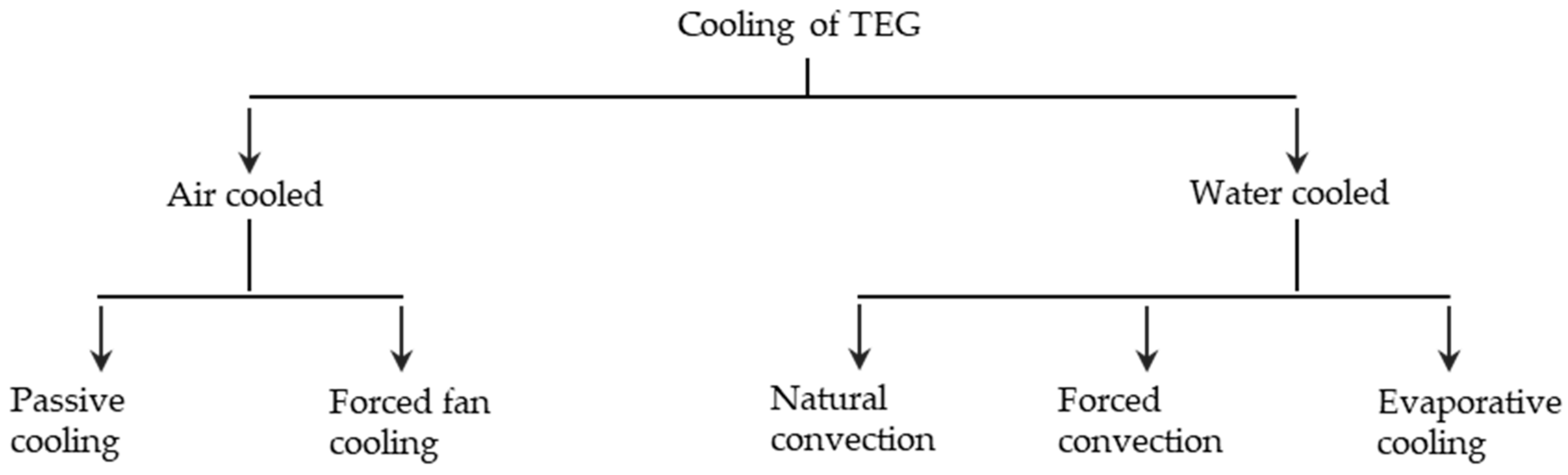
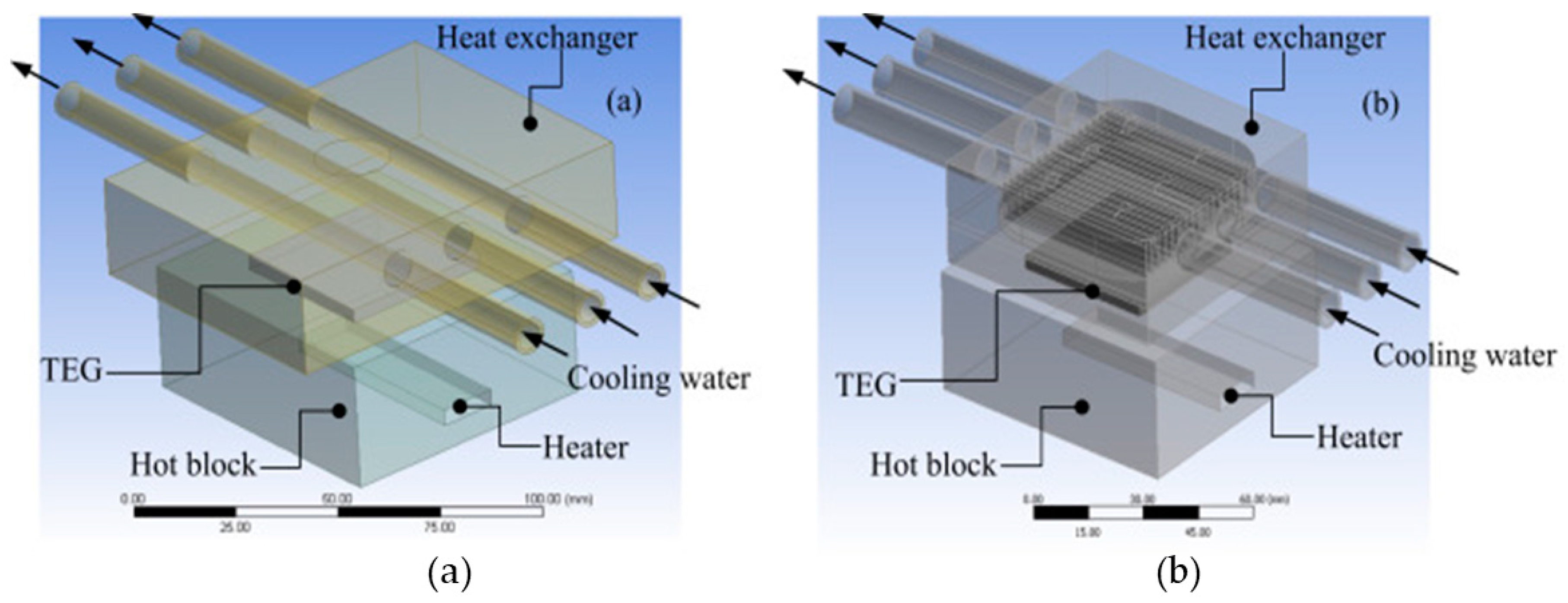
5. Cooling of Thermoelectric Generators
5.1. Air Cooling
5.1.1. Passive Air Cooling
5.1.2. Forced Air Cooling
5.1.3. Water Cooling
5.1.4. Natural Convection
5.1.5. Forced Convection
5.1.6. Evaporative Cooling
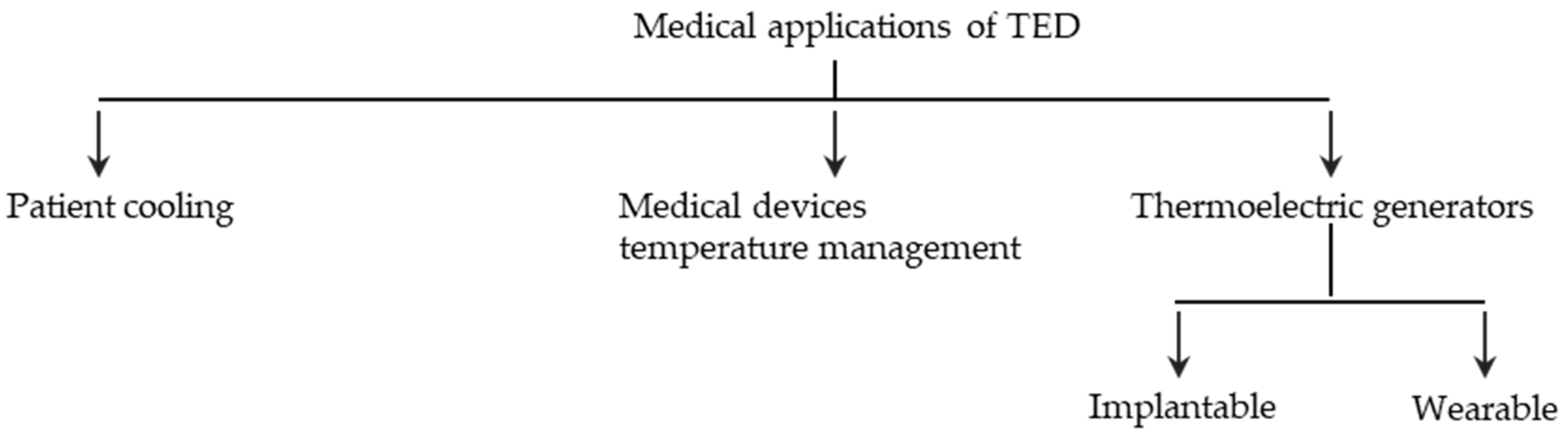
6. Medical Applications of Thermoelectric Generators
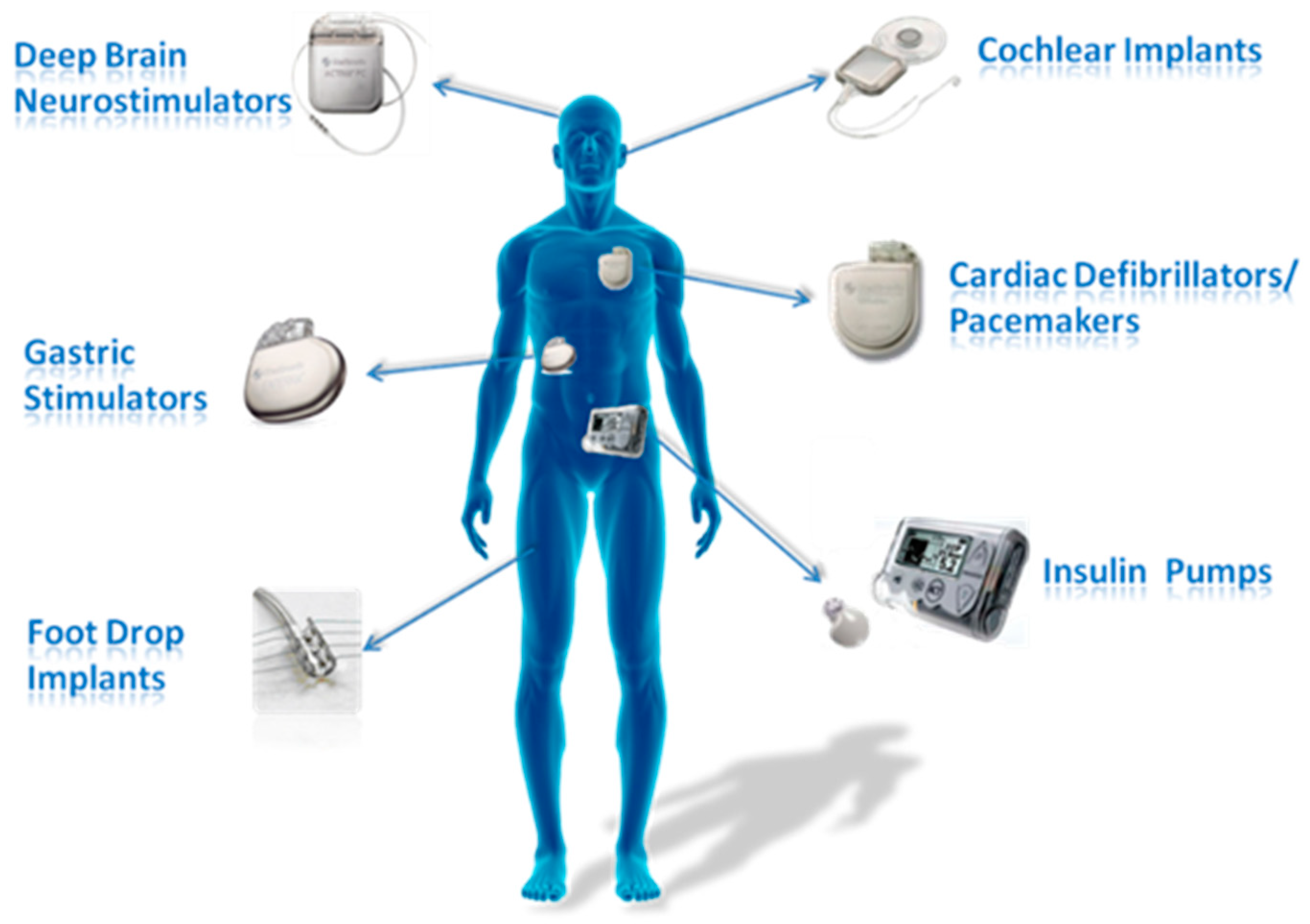
6.1. Thermoelectric Generators for Implantable Medical Devices
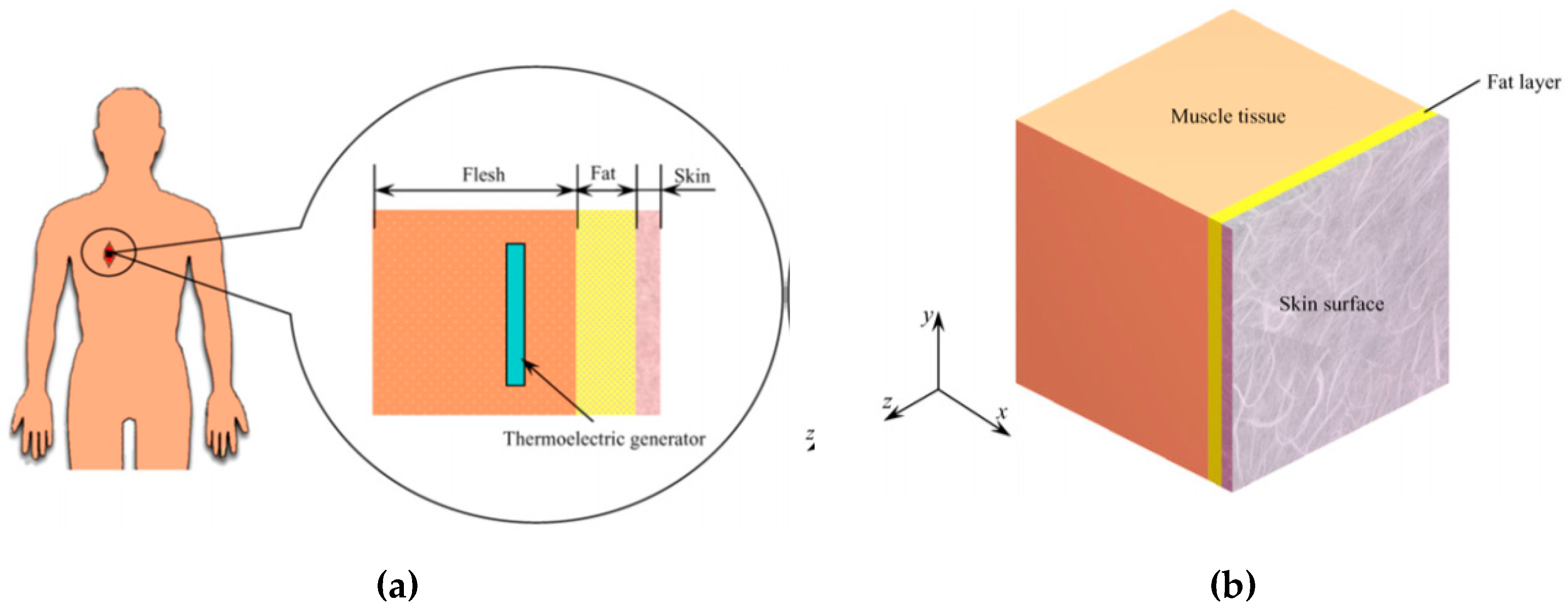
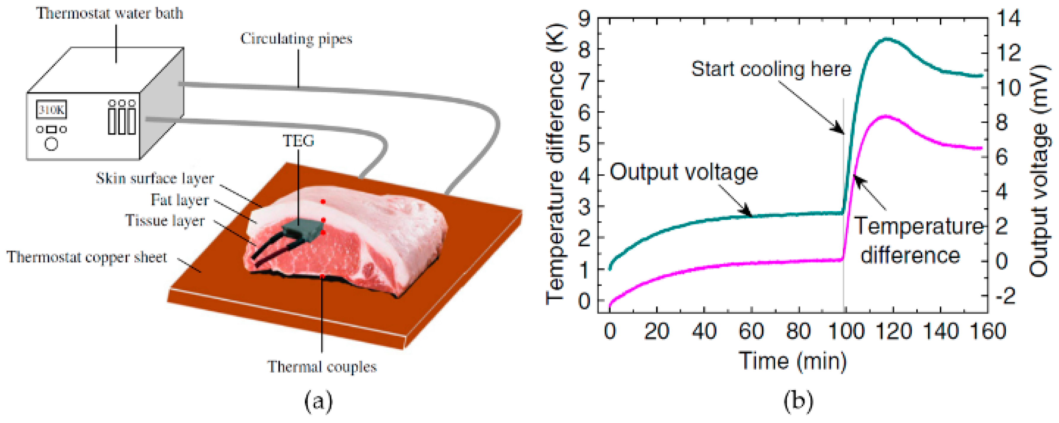
6.1.1. Design of TEGs for Implantable Devices.
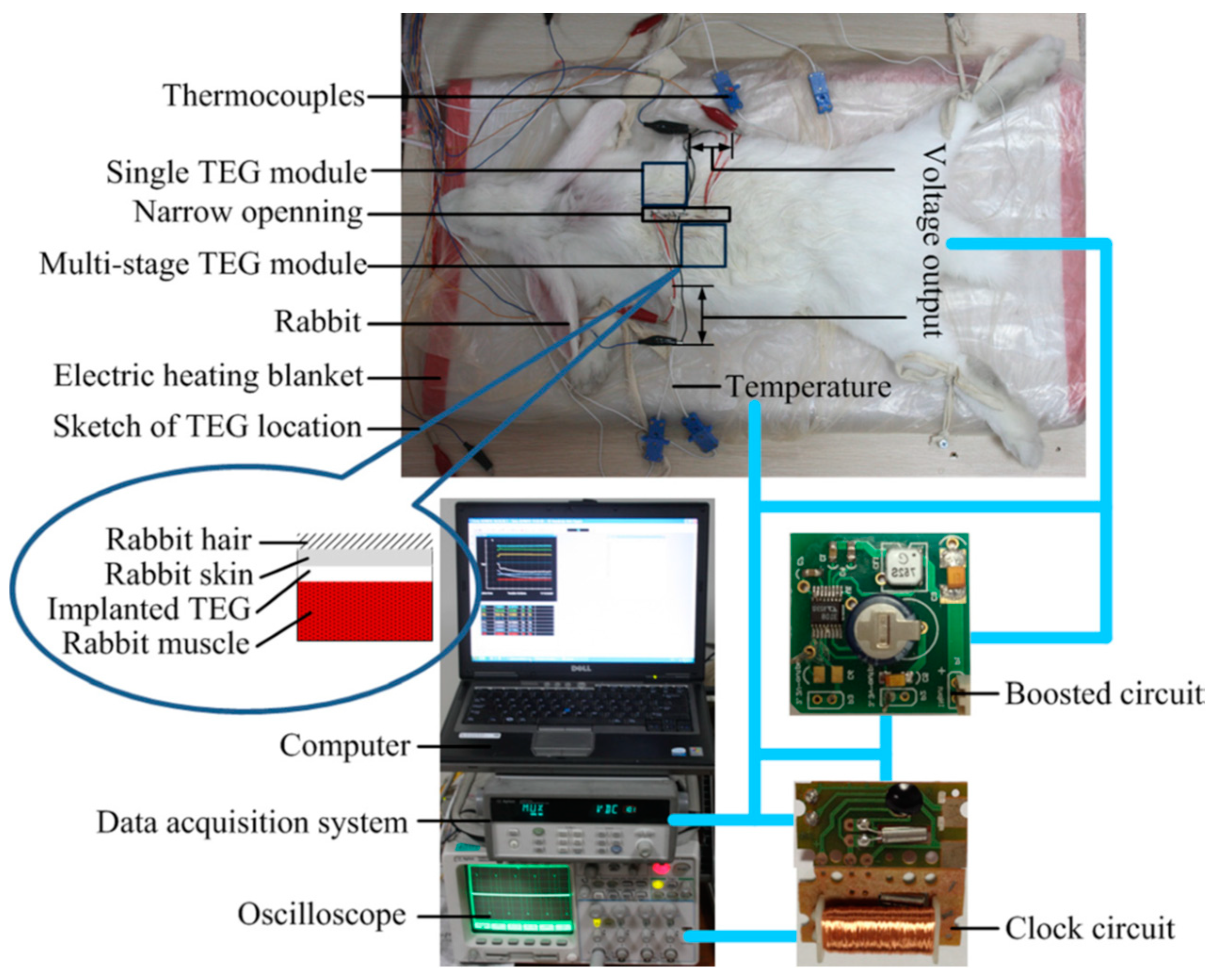
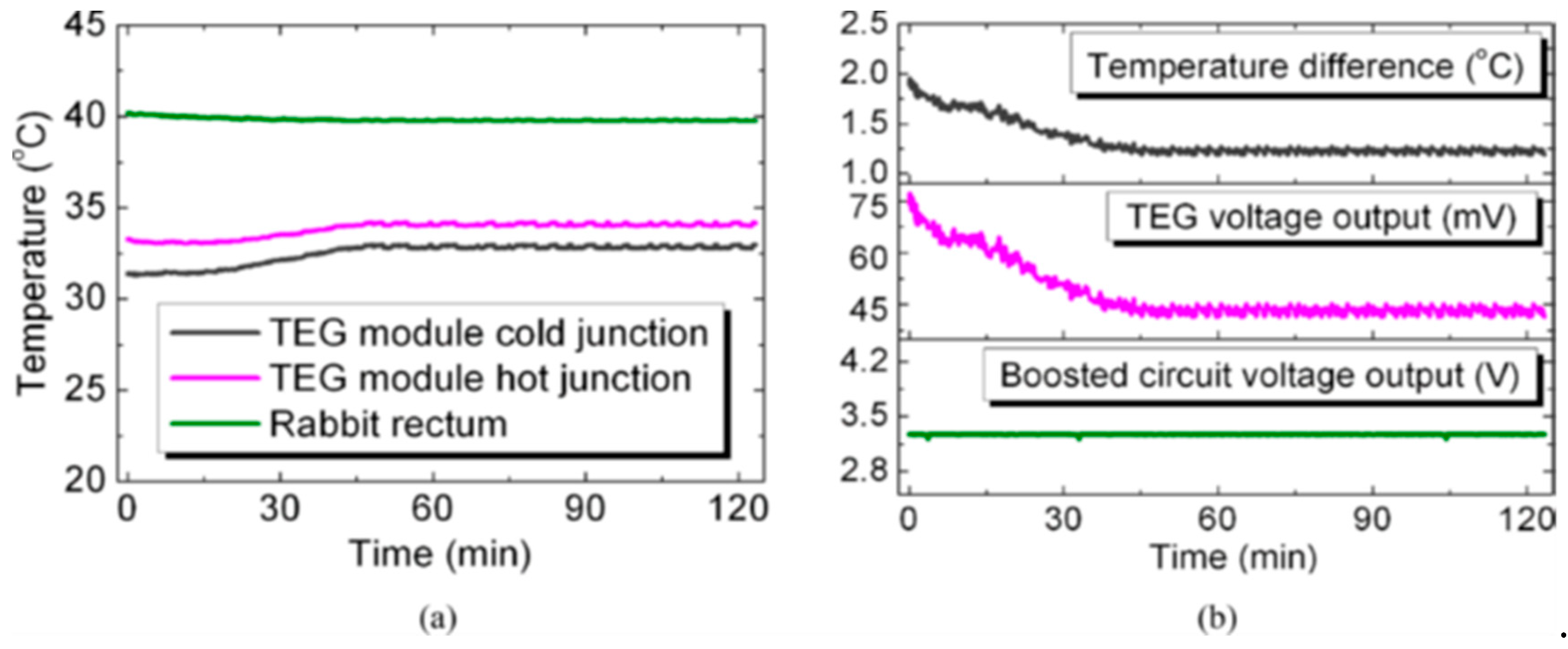
- The TEG can be located at an implantable depth from the skin surface, where the maximum temperature difference exists.
- Multi-stage TEG can generate higher power for the same temperature difference compared to single TEG.
- Skin cooling and higher ambient temperature will enhance the TEG output.
- As the voltage output from the TEG is not sufficient since the implantable device impedance is 0.5 to 100 kΩ [94], the commercially available thermoelectric module’s figure of merit has to be significantly increased.
- The TEG should be covered with high thermal conductivity and a biocompatible membrane before implanting it into the human body.
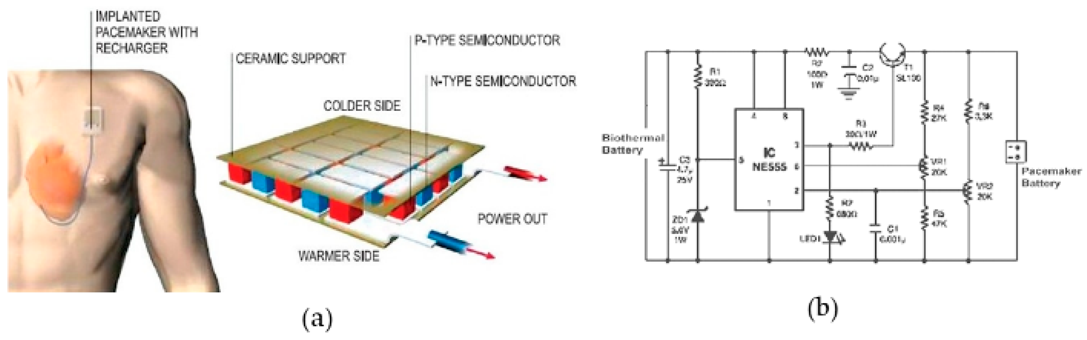
6.1.2. Pacemaker
6.2. Wearable Healthcare Devices
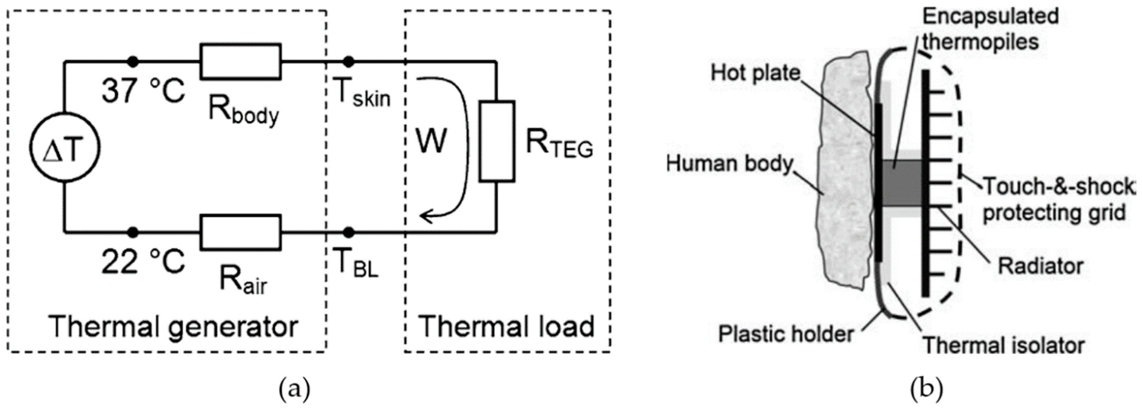
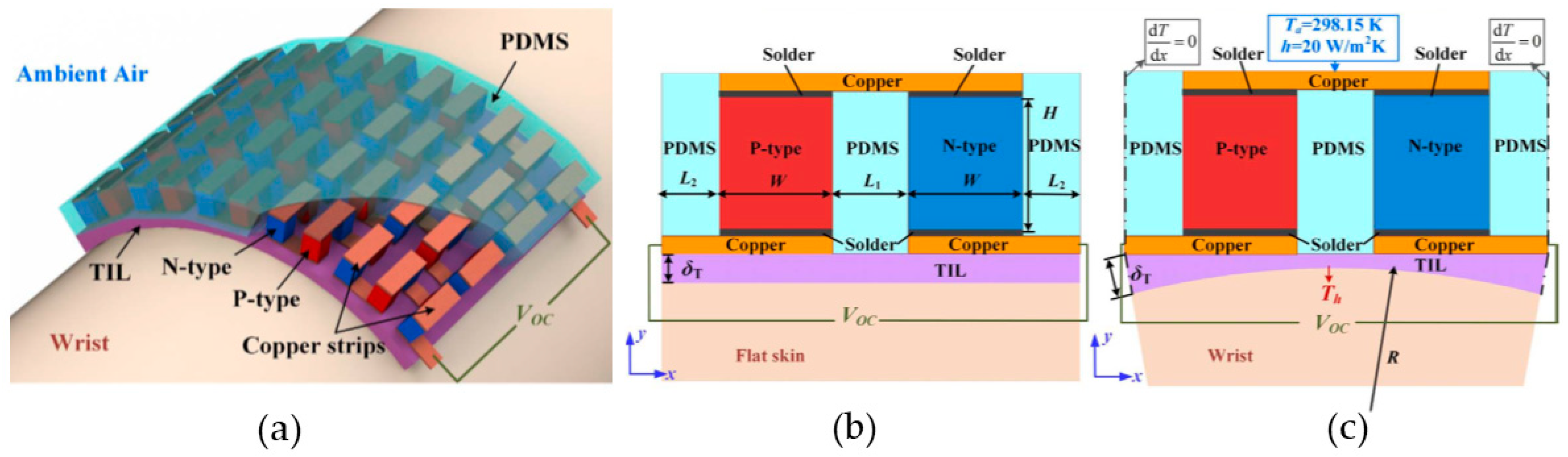
6.2.1. Design of a Wearable TEG
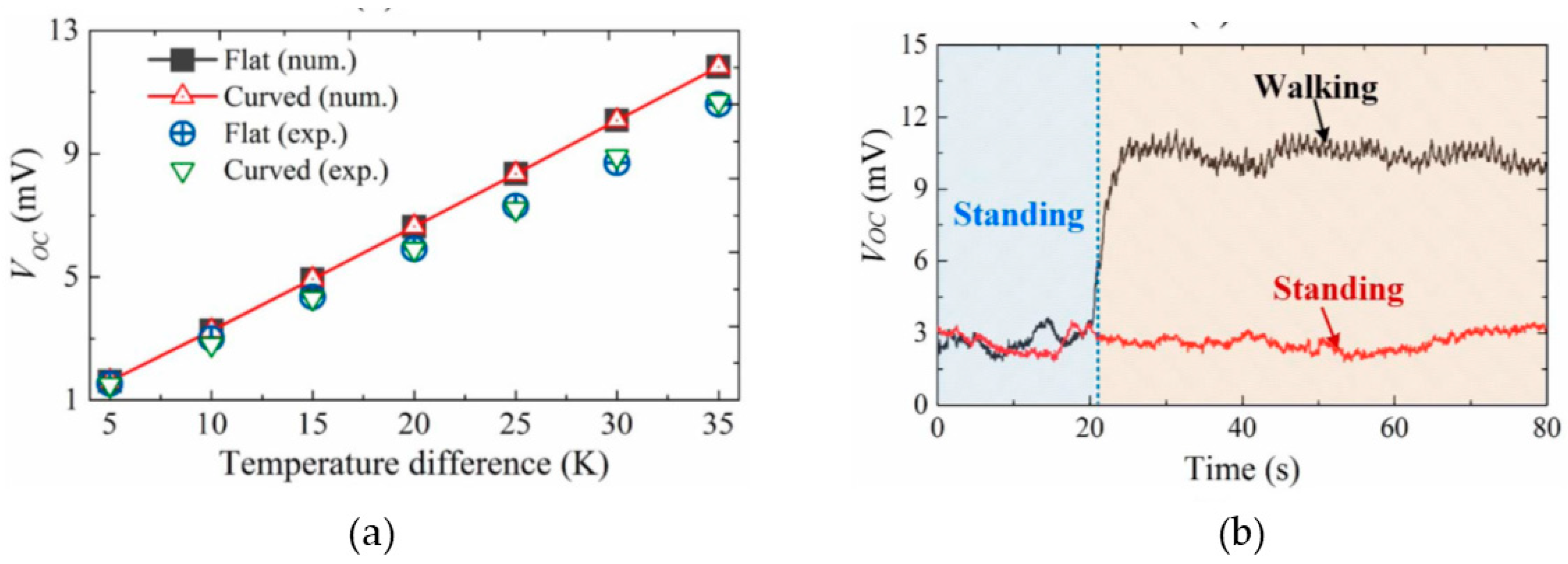
6.2.2. Flexible Thermoelectric Generators
7. Conclusions
Author Contributions
Funding
Conflicts of Interest
References
- Gould, C.; Shammas, N.; Grainger, S.; Taylor, I. A comprehensive review of thermoelectric technology, micro-electrical and power generation properties. In Proceedings of the 26th International Conference on Microelectronics, Nis, Serbia & Montenegro, 11–14 May 2008; pp. 329–332. [Google Scholar]
- DiSalvo, F.J. Thermoelectric cooling and power generation. Science 1999, 285, 703–706. [Google Scholar] [CrossRef]
- Bottner, H.; Nurnus, J.; Gavrikov, A.; Kuhner, G.; Jagle, M.; Kunzel, C.; Eberhard, D.; Plescher, G.; Schubert, A.; Schlereth, K.-H. New thermoelectric components using microsystem technologies. J. Microelectromech. Syst. 2004, 13, 414–420. [Google Scholar] [CrossRef]
- Snyder, G.J.; Soto, M.; Alley, R.; Koester, D.; Conner, B. Hot spot cooling using embedded thermoelectric coolers. In Proceedings of the Twenty-Second Annual IEEE Semiconductor Thermal Measurement and Management Symposium, Dallas, TX, USA, 14–16 March 2006; pp. 135–143. [Google Scholar]
- Rini, D.P.; Chow, L.; Anderson, H.R.; Kapat, J.S.; Carman, B.; Gulliver, B.; Recio, J.M. Method and Apparatus for Highly Efficient Compact Vapor Compression Cooling. U.S. Patent 7,010,936, 14 March 2006. [Google Scholar]
- O’Brien, R.; Ambrosi, R.; Bannister, N.; Howe, S.; Atkinson, H.V. Safe radioisotope thermoelectric generators and heat sources for space applications. J. Nucl. Mater. 2008, 377, 506–521. [Google Scholar] [CrossRef]
- Jung, K.K.; Jung, Y.; Choi, C.J.; Lee, J.M.; Ko, J.S. Flexible thermoelectric generator with polydimethyl siloxane in thermoelectric material and substrate. Curr. Appl. Phys. 2016, 16, 1442–1448. [Google Scholar] [CrossRef]
- Bell, L.E. Cooling, heating, generating power, and recovering waste heat with thermoelectric systems. Science 2008, 321, 1457–1461. [Google Scholar] [CrossRef] [PubMed]
- Tritt, T.M. Thermoelectric phenomena, materials, and applications. Annu. Rev. Mater. Res. 2011, 41, 433–448. [Google Scholar] [CrossRef]
- Shakouri, A. Recent developments in semiconductor thermoelectric physics and materials. Annu. Rev. Mater. Res. 2011, 41, 399–431. [Google Scholar] [CrossRef]
- Sootsman, J.R.; Chung, D.Y.; Kanatzidis, M.G. New and old concepts in thermoelectric materials. Angew. Chem. Int. Ed. 2009, 48, 8616–8639. [Google Scholar] [CrossRef] [PubMed]
- Elsheikh, M.H.; Shnawah, D.A.; Sabri, M.F.M.; Said, S.B.M.; Hassan, M.H.; Bashir, M.B.A.; Mohamad, M. A review on thermoelectric renewable energy: Principle parameters that affect their performance. Renew. Sustain. Energy Rev. 2014, 30, 337–355. [Google Scholar] [CrossRef]
- Riffat, S.B.; Ma, X. Thermoelectrics: A review of present and potential applications. Appl. Therm. Eng. 2003, 23, 913–935. [Google Scholar] [CrossRef]
- Snyder, G.J.; Toberer, E.S. Complex thermoelectric materials. In Materials for Sustainable Energy: A Collection of Peer-Reviewed Research and Review Articles from Nature Publishing Group; World Scientific Publishing Co Pte Ltd: Hackensack, NJ, USA, 2011; pp. 101–110. [Google Scholar]
- Chen, G.; Dresselhaus, M.; Dresselhaus, G.; Fleurial, J.-P.; Caillat, T. Recent developments in thermoelectric materials. Int. Mater. Rev. 2003, 48, 45–66. [Google Scholar] [CrossRef]
- Komabayashi, M.; Hijikata, K.-I.; Ido, S. Effects of some additives on thermoelectric properties of FeSi2 thin films. Jpn. J. Appl. Phys. 1991, 30, 331. [Google Scholar] [CrossRef]
- Kuhling, K.; Graeser, M.; Wendorff, J.H.; Greiner, A. Thermoelectric Nanomaterials. U.S. Patent Application 12/159,408, 1 January 2009. [Google Scholar]
- Zhao, L.-D.; Lo, S.-H.; Zhang, Y.; Sun, H.; Tan, G.; Uher, C.; Wolverton, C.; Dravid, V.P.; Kanatzidis, M.G. Ultralow thermal conductivity and high thermoelectric figure of merit in SnSe crystals. Nature 2014, 508, 373. [Google Scholar] [CrossRef]
- Kanatzidis, M.G.; Hogan, T.; Mahanti, S. Chemistry, Physics, and Materials Science of Thermoelectric Materials: Beyond Bismuth Telluride; Springer Science & Business Media: Berlin, Germany, 2012. [Google Scholar]
- Barako, M.; Park, W.; Marconnet, A.; Asheghi, M.; Goodson, K. Thermal cycling, mechanical degradation, and the effective figure of merit of a thermoelectric module. J. Electron. Mater. 2013, 42, 372–381. [Google Scholar] [CrossRef]
- Zhang, G.; Zhang, Y.-W. Strain effects on thermoelectric properties of two-dimensional materials. Mech. Mater. 2015, 91, 382–398. [Google Scholar] [CrossRef]
- Zhao, D.; Tian, C.; Liu, Y.; Zhan, C.; Chen, L. High temperature sublimation behavior of antimony in CoSb3 thermoelectric material during thermal duration test. J. Alloy. Compd. 2011, 509, 3166–3171. [Google Scholar] [CrossRef]
- Ren, F.; Wang, H.; Menchhofer, P.A.; Kiggans, J.O. Thermoelectric and mechanical properties of multi-walled carbon nanotube doped Bi0.4Sb1.6Te3 thermoelectric material. Appl. Phys. Lett. 2013, 103, 221907. [Google Scholar] [CrossRef]
- Ren, F.; Case, E.; Timm, E.; Schock, H. Hardness as a function of composition for n-type LAST thermoelectric material. J. Alloy. Compd. 2008, 455, 340–345. [Google Scholar] [CrossRef]
- Dresselhaus, M.; Chen, G.; Ren, Z.; Dresselhaus, G.; Henry, A.; Fleurial, J.-P. New composite thermoelectric materials for energy harvesting applications. JOM 2009, 61, 86–90. [Google Scholar] [CrossRef]
- Ravi, V.; Firdosy, S.; Caillat, T.; Brandon, E.; Van Der Walde, K.; Maricic, L.; Sayir, A. Thermal expansion studies of selected high-temperature thermoelectric materials. J. Electron. Mater. 2009, 38, 1433–1442. [Google Scholar] [CrossRef]
- Rogl, G.; Grytsiv, A.; Gürth, M.; Tavassoli, A.; Ebner, C.; Wünschek, A.; Puchegger, S.; Soprunyuk, V.; Schranz, W.; Bauer, E. Mechanical properties of half-Heusler alloys. Acta Mater. 2016, 107, 178–195. [Google Scholar] [CrossRef]
- Rogachev, M.; Pavlova, L.; Shtern, Y.I. Investigation of thermal linear expansion for nanostructured Si0.8Ge0.2P0.022 in wide temperature range. J. Phys. Conf. Ser. 2016, 741, 012203. [Google Scholar] [CrossRef]
- Thakur, S.; Dhindaw, B.; Hort, N.; Kainer, K. Some studies on the thermal-expansion behavior of c-fiber, SiCp, and in-situ Mg2 Si-Reinforced AZ31 Mg alloy-Based hybrid composites. Metall. Mater. Trans. A 2004, 35, 1167–1176. [Google Scholar] [CrossRef]
- Dai, D.; Zhou, Y.; Liu, J. Liquid metal based thermoelectric generation system for waste heat recovery. Renew. Energy 2011, 36, 3530–3536. [Google Scholar] [CrossRef]
- Sander, M.S.; Sharifi, F. Thermoelectric Nanotube Arrays. U.S. Patent Application 11/444,016, 6 December 2007. [Google Scholar]
- Schilz, J.; Riffel, M.; Pixius, K.; Meyer, H.-J. Synthesis of thermoelectric materials by mechanical alloying in planetary ball mills. Powder Technol. 1999, 105, 149–154. [Google Scholar] [CrossRef]
- Fukuda, K.; Sato, Y.; Kajihara, T. Thermoelectric Semiconductor Material, Manufacture Process Therefor, and Method of Hot Forging Thermoelectric Module Using the Same. U.S. Patent 6,274,802, 14 August 2001. [Google Scholar]
- Ur, S.-C.; Nash, P.; Kim, I.-H. Solid-state syntheses and properties of Zn4Sb3 thermoelectric materials. J. Alloy. Compd. 2003, 361, 84–91. [Google Scholar] [CrossRef]
- Yu, C.-B.; Gao, C.-F. Analysis of a circular arc-crack in thermoelectric media. In Proceedings of the 2016 Symposium on Piezoelectricity, Acoustic Waves, and Device Applications (SPAWDA), Xi’an, China, 21–24 October 2006; pp. 207–212. [Google Scholar]
- Ghoshal, U.S. Enhanced Interface Thermoelectric Coolers Using Etched Thermoelectric Material Tips. U.S. Patent 6,608,250, 19 August 2003. [Google Scholar]
- Cole, T. Thermoelectric energy conversion with solid electrolytes. Science 1983, 221, 915–920. [Google Scholar] [CrossRef]
- Lowhorn, N.D.; Wong-Ng, W.; Lu, Z.-Q.; Martin, J.; Green, M.L.; Bonevich, J.E.; Thomas, E.L.; Dilley, N.R.; Sharp, J. Development of a Seebeck coefficient Standard Reference Material™. J. Mater. Res. 2011, 26, 1983–1992. [Google Scholar] [CrossRef]
- Tsubota, T.; Ohtaki, M.; Eguchi, K.; Arai, H. Thermoelectric properties of Al-doped ZnO as a promising oxide material for high-temperature thermoelectric conversion. J. Mater. Chem. 1997, 7, 85–90. [Google Scholar] [CrossRef]
- Yu, C.; Choi, K.; Yin, L.; Grunlan, J.C. Light-weight flexible carbon nanotube based organic composites with large thermoelectric power factors. ACS Nano 2011, 5, 7885–7892. [Google Scholar] [CrossRef]
- Anatychuk, L.; Knyshov, G.; Krykunov, O.; Kobyliansky, R.; Tyumentsev, V.; Moskalyk, I. Thermoelectric Device «ALTEC-7012» for Human Head Cooling. Nauka Ta Innovacii 2016, 12, 60–67. [Google Scholar] [CrossRef]
- Weber, J.; Potje-Kamloth, K.; Haase, F.; Detemple, P.; Völklein, F.; Doll, T. Coin-size coiled-up polymer foil thermoelectric power generator for wearable electronics. Sens. Actuators A Phys. 2006, 132, 325–330. [Google Scholar] [CrossRef]
- Rojas, J.P.; Conchouso, D.; Arevalo, A.; Singh, D.; Foulds, I.G.; Hussain, M.M. based origami flexible and foldable thermoelectric nanogenerator. Nano Energy 2017, 31, 296–301. [Google Scholar] [CrossRef]
- Jo, S.; Kim, M.; Kim, M.; Kim, Y. Flexible thermoelectric generator for human body heat energy harvesting. Electron. Lett. 2012, 48, 1. [Google Scholar] [CrossRef]
- Schmitz, A.; Stiewe, C.; Müller, E. Preparation of ring-shaped thermoelectric legs from PbTe powders for tubular thermoelectric modules. J. Electron. Mater. 2013, 42, 1702–1706. [Google Scholar] [CrossRef]
- Min, G.; Rowe, D.M. Ring-structured thermoelectric module. Semicond. Sci. Technol. 2007, 22, 880. [Google Scholar] [CrossRef]
- Jovovic, V. Thermoelectric Waste Heat Recovery Program for Passenger Vehicles; Gentherm Incorporated: Azusa, CA, USA, 2015. [Google Scholar]
- Uchida, K.; Ishida, M.; Kikkawa, T.; Kirihara, A.; Murakami, T.; Saitoh, E. Longitudinal spin Seebeck effect: From fundamentals to applications. J. Phys. Condens. Matter 2014, 26, 343202. [Google Scholar] [CrossRef]
- Fateh, H.; Baker, C.A.; Hall, M.J.; Shi, L. High fidelity finite difference model for exploring multi-parameter thermoelectric generator design space. Appl. Energy 2014, 129, 373–383. [Google Scholar] [CrossRef]
- Hodes, M. Optimal pellet geometries for thermoelectric power generation. IEEE Trans. Compon. Packag. Technol. 2010, 33, 307–318. [Google Scholar] [CrossRef]
- Fabián-Mijangos, A.; Min, G.; Alvarez-Quintana, J. Enhanced performance thermoelectric module having asymmetrical legs. Energy Convers. Manag. 2017, 148, 1372–1381. [Google Scholar] [CrossRef]
- Kishita, Y.; Ohishi, Y.; Uwasu, M.; Kuroda, M.; Takeda, H.; Hara, K. Evaluating the life cycle CO2 emissions and costs of thermoelectric generators for passenger automobiles: A scenario analysis. J. Clean. Prod. 2016, 126, 607–619. [Google Scholar] [CrossRef]
- Snyder, G.J.; Lim, J.R.; Huang, C.-K.; Fleurial, J.-P. Thermoelectric microdevice fabricated by a MEMS-like electrochemical process. Nat. Mater. 2003, 2, 528. [Google Scholar] [CrossRef]
- Kao, P.-H.; Shih, P.-J.; Dai, C.-L.; Liu, M.-C. Fabrication and characterization of CMOS-MEMS thermoelectric micro generators. Sensors 2010, 10, 1315–1325. [Google Scholar] [CrossRef]
- Glosch, H.; Ashauer, M.; Pfeiffer, U.; Lang, W. A thermoelectric converter for energy supply. Sens. Actuators A Phys. 1999, 74, 246–250. [Google Scholar] [CrossRef]
- Zebarjadi, M. Heat Management in Thermoelectric Power Generators. Sci. Rep. 2016, 6, 20951. [Google Scholar] [CrossRef]
- Jaworski, M.; Bednarczyk, M.; Czachor, M. Experimental investigation of thermoelectric generator (TEG) with PCM module. Appl. Therm. Eng. 2016, 96, 527–533. [Google Scholar] [CrossRef]
- Rowe, D.M. Conversion Efficiency and Figure-of-Merit. In CRC Handbook of Thermoelectrics; CRC Press: Boca Raton, FL, USA, 1995; pp. 31–37. [Google Scholar]
- Özdemir, A.E.; Köysal, Y.; Özbaş, E.; Atalay, T. The experimental design of solar heating thermoelectric generator with wind cooling chimney. Energy Convers. Manag. 2015, 98, 127–133. [Google Scholar] [CrossRef]
- Wang, C.-C.; Hung, C.-I.; Chen, W.-H. Design of heat sink for improving the performance of thermoelectric generator using two-stage optimization. Energy 2012, 39, 236–245. [Google Scholar] [CrossRef]
- Mastbergen, D.; Willson, B.; Joshi, S. Producing light from stoves using a thermoelectric generator. Ethos 2005, 2005. [Google Scholar]
- Hsu, C.-T.; Yao, D.-J.; Ye, K.-J.; Yu, B. Renewable energy of waste heat recovery system for automobiles. J. Renew. Sustain. Energy 2010, 2, 013105. [Google Scholar] [CrossRef]
- Lee, Y.G.; Kim, J.; Kang, M.S.; Baek, S.H.; Kim, S.K.; Lee, S.M.; Lee, J.; Hyun, D.B.; Ju, B.K.; Moon, S.E. Design and Experimental Investigation of Thermoelectric Generators for Wearable Applications. Adv. Mater. Technol. 2017, 2, 1600292. [Google Scholar] [CrossRef]
- Lv, H.; Li, G.; Zheng, Y.; Hu, J.; Li, J. Compact water-cooled thermoelectric generator (TEG) based on a portable gas stove. Energies 2018, 11, 2231. [Google Scholar] [CrossRef]
- Kiflemariam, R.; Lin, C.-X. Numerical simulation of integrated liquid cooling and thermoelectric generation for self-cooling of electronic devices. Int. J. Therm. Sci. 2015, 94, 193–203. [Google Scholar] [CrossRef]
- Champier, D.; Bédécarrats, J.-P.; Kousksou, T.; Rivaletto, M.; Strub, F.; Pignolet, P. Study of a TE (thermoelectric) generator incorporated in a multifunction wood stove. Energy 2011, 36, 1518–1526. [Google Scholar] [CrossRef]
- Sajid, M.; Hassan, I.; Rahman, A. An overview of cooling of thermoelectric devices. Renew. Sustain. Energy Rev. 2017, 78, 15–22. [Google Scholar] [CrossRef]
- Singh, R.; Tundee, S.; Akbarzadeh, A. Electric power generation from solar pond using combined thermosyphon and thermoelectric modules. Sol. Energy 2011, 85, 371–378. [Google Scholar] [CrossRef]
- Niu, X.; Yu, J.; Wang, S. Experimental study on low-temperature waste heat thermoelectric generator. J. Power Sources 2009, 188, 621–626. [Google Scholar] [CrossRef]
- Yazawa, K.; Wong, V.K.; Shakouri, A. Thermal challenges on solar concentrated thermoelectric CHP systems. In Proceedings of the 13th InterSociety Conference on Thermal and Thermomechanical Phenomena in Electronic Systems, San Diego, CA, USA, 30 May–1 June 2012; pp. 1144–1150. [Google Scholar]
- Fan, H.; Singh, R.; Akbarzadeh, A. Electric power generation from thermoelectric cells using a solar dish concentrator. J. Electron. Mater. 2011, 40, 1311–1320. [Google Scholar] [CrossRef]
- Aranguren, P.; Astrain, D.; Martínez, A. Study of complete thermoelectric generator behavior including water-to-ambient heat dissipation on the cold side. J. Electron. Mater. 2014, 43, 2320–2330. [Google Scholar] [CrossRef]
- Li, W.; Paul, M.; Siviter, J.; Montecucco, A.; Knox, A.; Sweet, T.; Min, G.; Baig, H.; Mallick, T.; Han, G. Thermal performance of two heat exchangers for thermoelectric generators. Case Stud. Therm. Eng. 2016, 8, 164–175. [Google Scholar] [CrossRef]
- Nuwayhid, R.; Hamade, R. Design and testing of a locally made loop-type thermosyphonic heat sink for stove-top thermoelectric generators. Renew. Energy 2005, 30, 1101–1116. [Google Scholar] [CrossRef]
- Djafar, Z.; Putra, N.; Koestoer, R.A. The utilization of heat pipe on cold surface of thermoelectric with low-temperature waste heat. Appl. Mech. Mater. 2013, 302, 410–415. [Google Scholar] [CrossRef]
- He, W.; Su, Y.; Riffat, S.; Hou, J.; Ji, J. Parametrical analysis of the design and performance of a solar heat pipe thermoelectric generator unit. Appl. Energy 2011, 88, 5083–5089. [Google Scholar] [CrossRef]
- Boonyasri, M.; Jamradloedluk, J.; Lertsatitthanakorn, C.; Therdyothin, A.; Soponronnarit, S. Increasing the Efficiency of a Thermoelectric Generator Using an Evaporative Cooling System. J. Electron. Mater. 2017, 46, 3043–3048. [Google Scholar] [CrossRef]
- Espinosa, N.; Lazard, M.; Aixala, L.; Scherrer, H. Modeling a thermoelectric generator applied to diesel automotive heat recovery. J. Electron. Mater. 2010, 39, 1446–1455. [Google Scholar] [CrossRef]
- Haghi, M.; Thurow, K.; Stoll, R. Wearable devices in medical internet of things: Scientific research and commercially available devices. Healthc. Inform. Res. 2017, 23, 4–15. [Google Scholar] [CrossRef] [PubMed]
- Tsui, C.-Y.; Li, X.; Ki, W.-H. Energy harvesting and power delivery for implantable medical devices. Found. Trends Electron. Des. Autom. 2013, 7, 179–246. [Google Scholar] [CrossRef]
- Spencer, W. A review of programmed insulin delivery systems. IEEE Trans. Biomed. Eng. 1981, 28, 237–251. [Google Scholar] [CrossRef]
- Moss, A.J.; Hall, W.J.; Cannom, D.S.; Daubert, J.P.; Higgins, S.L.; Klein, H.; Levine, J.H.; Saksena, S.; Waldo, A.L.; Wilber, D. Improved survival with an implanted defibrillator in patients with coronary disease at high risk for ventricular arrhythmia. N. Engl. J. Med. 1996, 335, 1933–1940. [Google Scholar] [CrossRef]
- Adams, T.P. Wireless Programmer/Repeater System for an Implanted Medical Device. U.S. Patent 5,383,915, 24 January 1995. [Google Scholar]
- Schmidt, C.L.; Skarstad, P.M. The future of lithium and lithium-ion batteries in implantable medical devices. J. Power Sources 2001, 97, 742–746. [Google Scholar] [CrossRef]
- Gollakota, S.; Hassanieh, H.; Ransford, B.; Katabi, D.; Fu, K. They can hear your heartbeats: Non-invasive security for implantable medical devices. In Proceedings of the ACM SIGCOMM Computer Communication Review, Toronto, ON, Canada, 15–19 August 2011; pp. 2–13. [Google Scholar]
- Horiba, T.; Maeshima, T.; Matsumura, T.; Koseki, M.; Arai, J.; Muranaka, Y. Applications of high power density lithium ion batteries. J. Power Sources 2005, 146, 107–110. [Google Scholar] [CrossRef]
- Diouf, B.; Pode, R. Potential of lithium-ion batteries in renewable energy. Renew. Energy 2015, 76, 375–380. [Google Scholar] [CrossRef]
- Majeau-Bettez, G.; Hawkins, T.R.; Strømman, A.H. Life cycle environmental assessment of lithium-ion and nickel metal hydride batteries for plug-in hybrid and battery electric vehicles. Environ. Sci. Technol. 2011, 45, 4548–4554. [Google Scholar] [CrossRef]
- Jaeger, J.; Deal, E., Jr.; Roberts, D.; McFadden, E., Jr. Cold Air Inhalation, Esophageal Temperature and Lung Function in Exercising Humans; Army Research Inst of Environmental Medicine: Natick, MA, USA, 1979. [Google Scholar]
- Cohen, M.L. Measurement of the thermal properties of human skin. A review. J. Investig. Dermatol. 1977, 69, 333–338. [Google Scholar] [CrossRef]
- Xuan, Y.; Roetzel, W. Bioheat equation of the human thermal system. Chem. Eng. Technol. Ind. Chem. Plant Equip. Process Eng. Biotechnol. 1997, 20, 268–276. [Google Scholar] [CrossRef]
- Fiala, D.; Lomas, K.J.; Stohrer, M. A computer model of human thermoregulation for a wide range of environmental conditions: The passive system. J. Appl. Physiol. 1999, 87, 1957–1972. [Google Scholar] [CrossRef] [PubMed]
- Ishida, Y.; Carroll, J.; Pollock, M.; Graves, J.; Leggett, S. Reliability of B-mode ultrasound for the measurement of body fat and muscle thickness. Am. J. Hum. Biol. 1992, 4, 511–520. [Google Scholar] [CrossRef]
- Olivo, J.; Carrara, S.; De Micheli, G. Energy harvesting and remote powering for implantable biosensors. IEEE Sens. J. 2011, 11, 1573–1586. [Google Scholar] [CrossRef]
- Parsonnet, V. Power sources for implantable cardiac pacemakers. Chest 1972, 61, 165–173. [Google Scholar] [CrossRef]
- Mallela, V.S.; Ilankumaran, V.; Rao, N.S. Trends in cardiac pacemaker batteries. Indian Pacing Electrophysiol. J. 2004, 4, 201. [Google Scholar]
- Bhatia, D.; Bairagi, S.; Goel, S.; Jangra, M. Pacemakers charging using body energy. J. Pharm. Bioallied Sci. 2010, 2, 51. [Google Scholar] [CrossRef]
- Moontasir, H.; Ravigururajan, T.S. Bio-Thermal Battery for ICDs; Wichita State University: Wichita, KS, USA, 2006. [Google Scholar]
- Choi, M.Y.; Choi, D.; Jin, M.J.; Kim, I.; Kim, S.H.; Choi, J.Y.; Lee, S.Y.; Kim, J.M.; Kim, S.W. Mechanically powered transparent flexible charge-generating nanodevices with piezoelectric ZnO nanorods. Adv. Mater. 2009, 21, 2185–2189. [Google Scholar] [CrossRef]
- Kulkarni, P.; Öztürk, Y. Requirements and design spaces of mobile medical care. Acm Sigmobile Mob. Comput. Commun. Rev. 2007, 11, 12–30. [Google Scholar] [CrossRef]
- Feng, D.; Jiang, C.; Lim, G.; Cimini, L.J.; Feng, G.; Li, G.Y. A survey of energy-efficient wireless communications. IEEE Commun. Surv. Tutor. 2013, 15, 167–178. [Google Scholar] [CrossRef]
- Bronzino, J.D. Principles of electroencephalography. In The Biomedical Engineering Handbook; 1995; Volume 1. [Google Scholar]
- Bos, R. Self-Starting of a Small Urban Darrieus Rotor; Delft University of Technology: Delft, The Netherlands, 2012. [Google Scholar]
- Respironics, P. VitalSense. Available online: http://www.actigraphy.com/ (accessed on 2 February 2019).
- Vivonoetics. Vivosense. Available online: https://www.vivosense.com/ (accessed on 2 February 2019).
- Tjiu, W.; Marnoto, T.; Mat, S.; Ruslan, M.H.; Sopian, K. Darrieus vertical axis wind turbine for power generation II: Challenges in HAWT and the opportunity of multi-megawatt Darrieus VAWT development. Renew. Energy 2015, 75, 560–571. [Google Scholar] [CrossRef]
- Ward, J.; Eaton, J.; Hale, H. Losses in power transmission networks. Electr. Eng. 1950, 69, 451. [Google Scholar] [CrossRef]
- Curone, D.; Secco, E.L.; Tognetti, A.; Loriga, G.; Dudnik, G.; Risatti, M.; Whyte, R.; Bonfiglio, A.; Magenes, G. Smart garments for emergency operators: The ProeTEX project. IEEE Trans. Inf. Technol. Biomed. 2010, 14, 694–701. [Google Scholar] [CrossRef]
- Lee, D.; Haymes, E.M. Exercise duration and thermoregulatory responses after whole body precooling. J. Appl. Physiol. 1995, 79, 1971–1976. [Google Scholar] [CrossRef]
- Torfs, T.; Leonov, V.; Van Hoof, C.; Gyselinckx, B. Body-heat powered autonomous pulse oximeter. In Proceedings of the 5th IEEE Sensors, Daegu, South Korea, 22–25 October 2006; pp. 427–430. [Google Scholar]
- Leonov, V.; Vullers, R. Wearable thermoelectric generators for body-powered devices. J. Electron. Mater. 2009, 38, 1491–1498. [Google Scholar] [CrossRef]
- Leonov, V. Energy harvesting for self-powered wearable devices. In Wearable Monitoring Systems; Springer: Berlin, Germany, 2011; pp. 27–49. [Google Scholar]
- Torfs, T.; Leonov, V.; Yazicioglu, R.F.; Merken, P.; Van Hoof, C.; Vullers, R.J.; Gyselinckx, B. Wearable autonomous wireless electro-encephalography system fully powered by human body heat. In Proceedings of the IEEE Sensors, Lecce, Italy, 26–29 October 2008; pp. 1269–1272. [Google Scholar]
- Suarez, F.; Nozariasbmarz, A.; Vashaee, D.; Öztürk, M.C. Designing thermoelectric generators for self-powered wearable electronics. Energy Environ. Sci. 2016, 9, 2099–2113. [Google Scholar] [CrossRef]
- Wang, Y.; Shi, Y.; Mei, D.; Chen, Z. Wearable thermoelectric generator for harvesting heat on the curved human wrist. Appl. Energy 2017, 205, 710–719. [Google Scholar] [CrossRef]
- Proto, A.; Bibbo, D.; Cerny, M.; Vala, D.; Kasik, V.; Peter, L.; Conforto, S.; Schmid, M.; Penhaker, M. Thermal energy harvesting on the bodily surfaces of arms and legs through a wearable thermo-electric generator. Sensors 2018, 18, 1927. [Google Scholar] [CrossRef]


| Implanted Device. | Applications | Typical Power Requirement |
|---|---|---|
| Cardiac pacemaker | Conduction disorders | 30–100 μW |
| Cardiac defibrillator | Ventricular tachycardia | 30–100 μW (Idle) |
| Neurological stimulator | Essential tremor | 30 μW to several mW |
| Drug pump | Spasticity | 100 μW–2 mW |
| Cochlear implant | Auditory assistance | Up to 10 mW |
| Glucose monitor | Diabetes care | >10 μW |
| Material | Thermal Conductivity | Density | Heat Capacity |
|---|---|---|---|
| Muscle | 0.7–1.0 W/m K | 1070 kg/m3 | 3471 J/kg K |
| Fat | 0.1–0.4 W/m K | 937 kg/m3 | 3258 J/kg K |
| Skin | 0.5–2.8 W/m K | — | — |
| Blood | 0.51–0.53 W/m K | 1060 kg/m3 | 3889 J/kg K |
| Model | Manufacturer | Ref |
|---|---|---|
| Health Vest | Smart Life Technologies | [103] |
| Vital Sense. | Philips-Respironics | [104] |
| Life Shirt | Vivo Metrics | [105] |
| Equivital | Bio-Lynx Scientific Equipment, Inc. | [106] |
| Bioharness | Zephyr | [107] |
| ProeTEX | Curone | [108] |
| ExMedicus Smartwatch | Planet Intelligent | [106] |
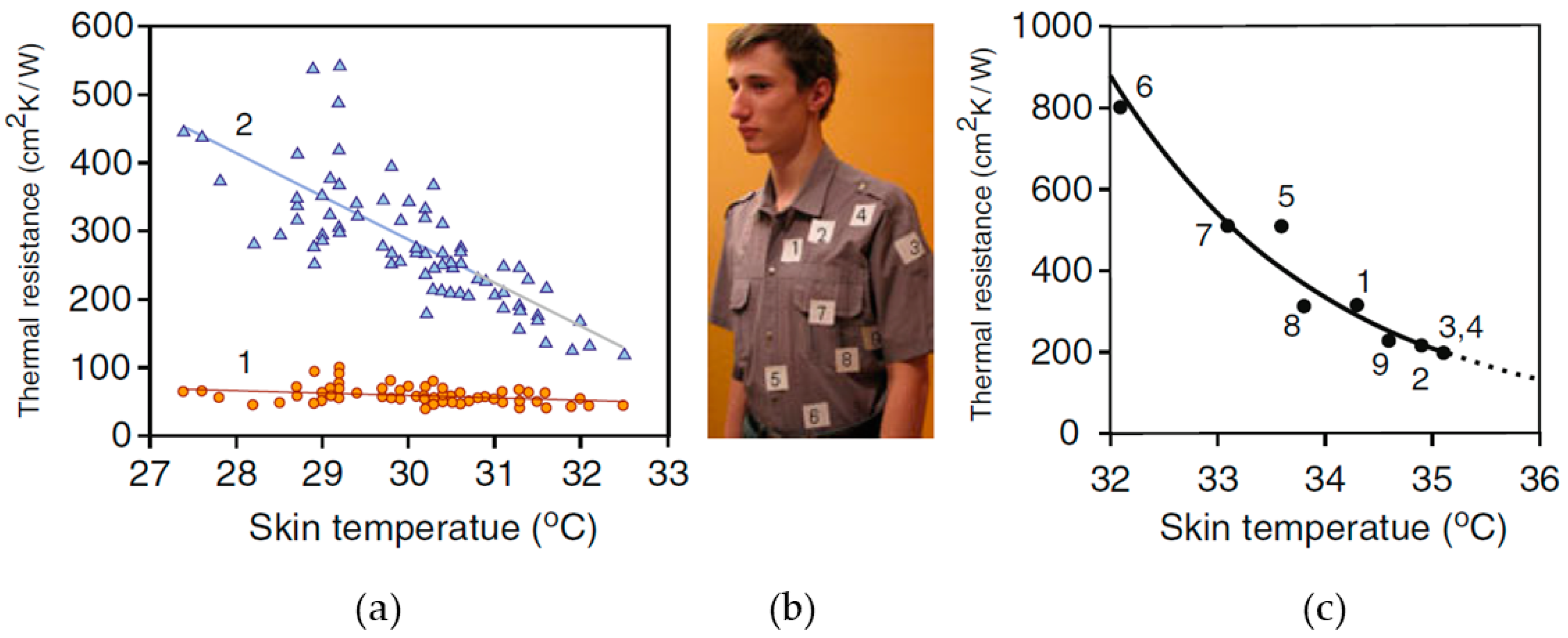
| Body Location | Ambient Temperature °C | Thermal Resistance cm2 K/W |
|---|---|---|
| Trunk | 23 | 200–800 |
| Outer wrist | 22.7 | 440 |
| Inner wrist | 22.7 | 120–150 |
| Forehead | 21.5 | 156–380 |
© 2019 by the authors. Licensee MDPI, Basel, Switzerland. This article is an open access article distributed under the terms and conditions of the Creative Commons Attribution (CC BY) license (http://creativecommons.org/licenses/by/4.0/).
Share and Cite
Kumar, P.M.; Jagadeesh Babu, V.; Subramanian, A.; Bandla, A.; Thakor, N.; Ramakrishna, S.; Wei, H. The Design of a Thermoelectric Generator and Its Medical Applications. Designs 2019, 3, 22. https://doi.org/10.3390/designs3020022
Kumar PM, Jagadeesh Babu V, Subramanian A, Bandla A, Thakor N, Ramakrishna S, Wei H. The Design of a Thermoelectric Generator and Its Medical Applications. Designs. 2019; 3(2):22. https://doi.org/10.3390/designs3020022
Chicago/Turabian StyleKumar, Palanisamy Mohan, Veluru Jagadeesh Babu, Arjun Subramanian, Aishwarya Bandla, Nitish Thakor, Seeram Ramakrishna, and He Wei. 2019. "The Design of a Thermoelectric Generator and Its Medical Applications" Designs 3, no. 2: 22. https://doi.org/10.3390/designs3020022
APA StyleKumar, P. M., Jagadeesh Babu, V., Subramanian, A., Bandla, A., Thakor, N., Ramakrishna, S., & Wei, H. (2019). The Design of a Thermoelectric Generator and Its Medical Applications. Designs, 3(2), 22. https://doi.org/10.3390/designs3020022