

Effects of Thigh and Leg Rotation on Sagittal Knee Angle During Static Assessment

 ,
, 
 , and
, and
Abstract
1. Introduction
2. Methods
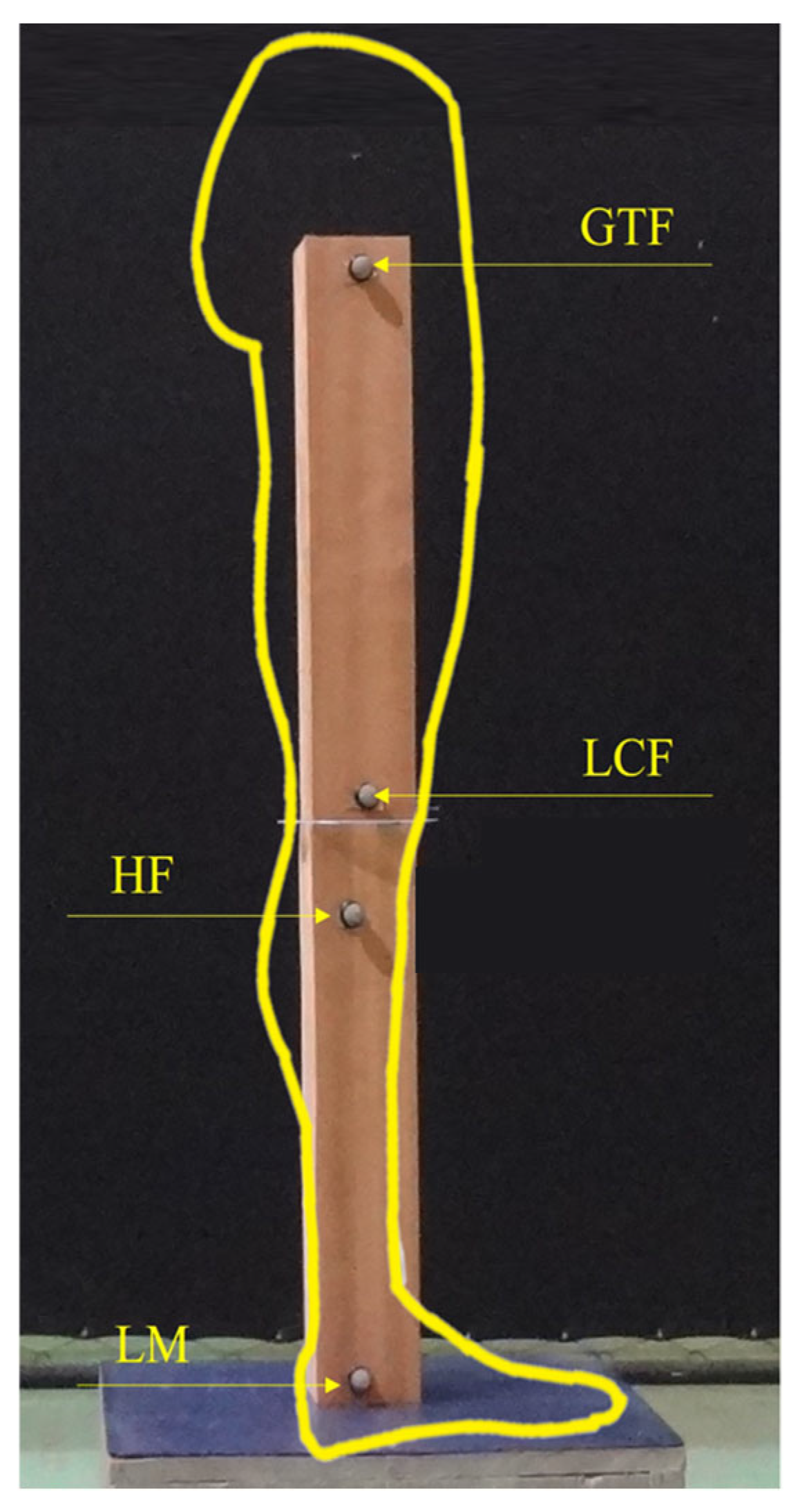
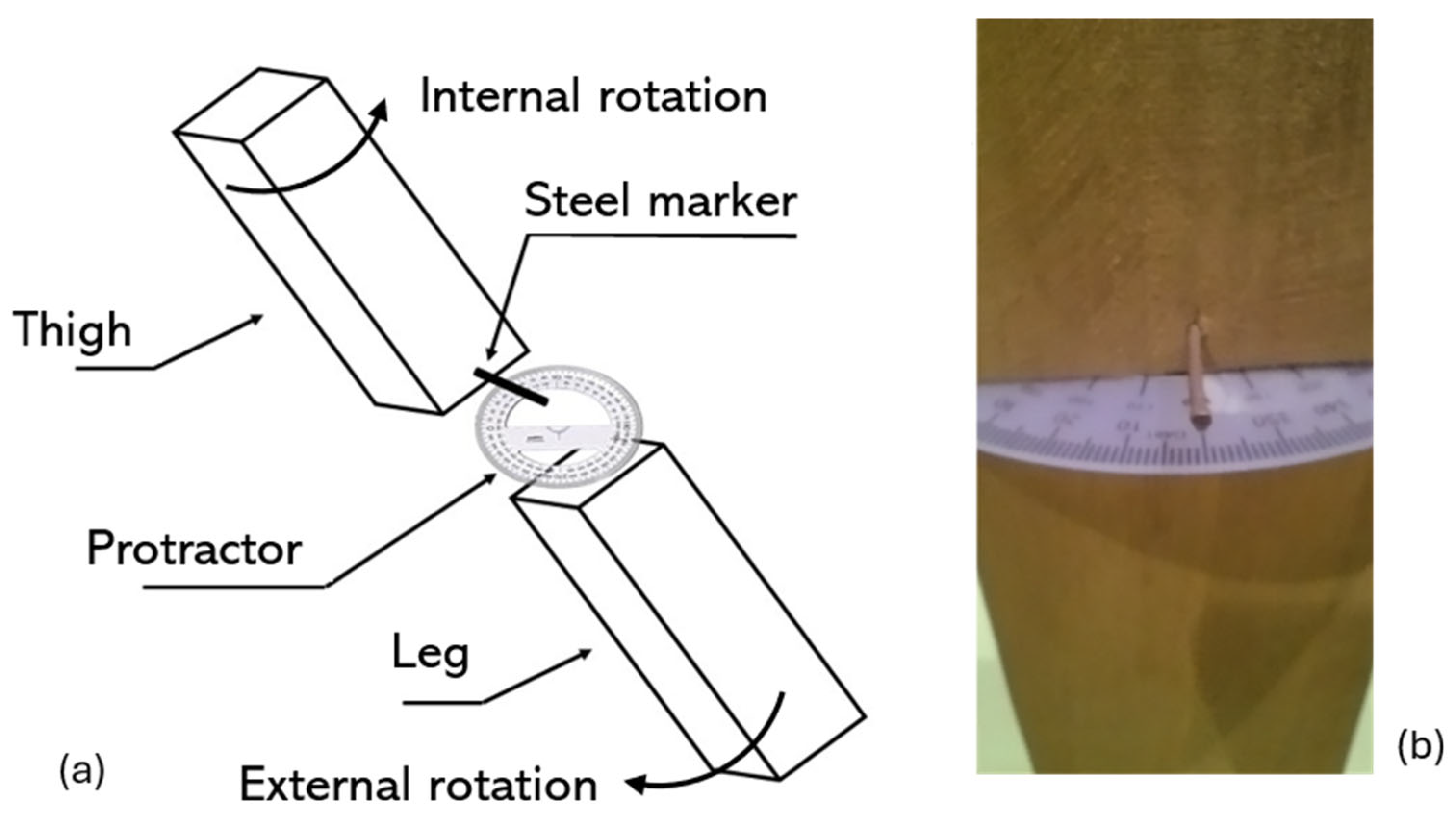
2.1. Physical Model
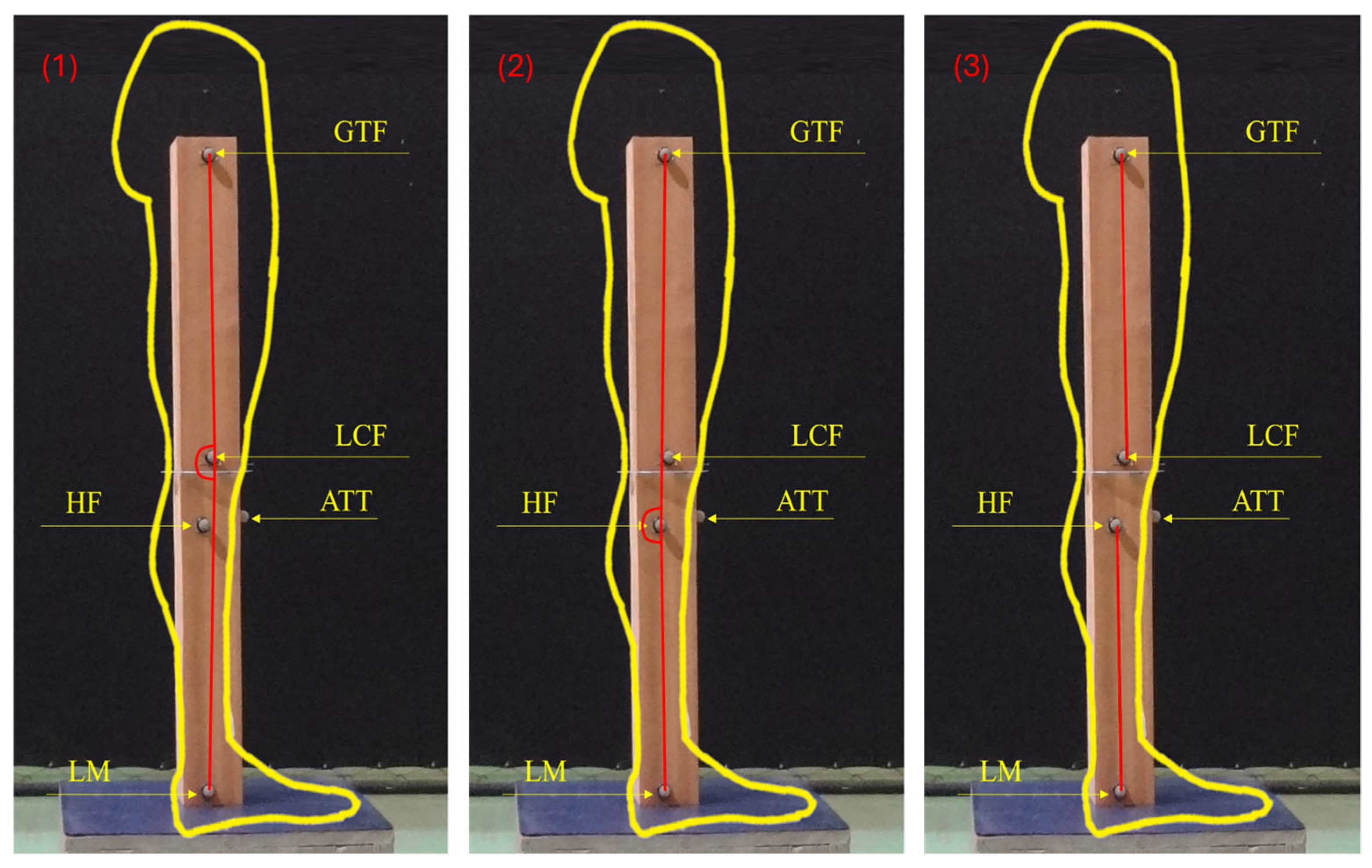
2.2. Knee Flexion Angles Protocols
2.3. Data Analysis
3. Results
4. Discussion
5. Conclusions
Author Contributions
Funding
Institutional Review Board Statement
Informed Consent Statement
Data Availability Statement
Acknowledgments
Conflicts of Interest
References
- Do Rosário, J.L.P. Photographic Analysis of Human Posture: A Literature Review. J. Bodyw. Mov. Ther. 2014, 18, 56–61. [Google Scholar] [CrossRef]
- Missaoui, B.; Portero, P.; Bendaya, S.; Hanktie, O.; Thoumie, P. Posture and Equilibrium in Orthopedic and Rheumatologic Diseases. Neurophysiol. Clin. 2008, 38, 447–457. [Google Scholar] [CrossRef] [PubMed]
- Trombini-Souza, F.; Ribeiro, A.P.; Iunes, D.H.; Monte-Raso, V.V. Correlações Entre as Estruturas Dos Membros Inferiores. Fisioter. Pesqui. 2009, 16, 205–210. [Google Scholar] [CrossRef]
- Brouwer, G.M.; Tol, A.W.V.; Bergink, A.P.; Belo, J.N.; Bernsen, R.M.D.; Reijman, M.; Pols, H.A.P.; Bierma-Zeinstra, S.M.A. Association Between Valgus and Varus Alignment and the Development and Progression of Radiographic Osteoarthritis of the Knee. Arthritis Rheum. 2007, 56, 1204–1211. [Google Scholar] [CrossRef]
- Hinman, R.S.; May, R.L.; Crossley, K.A.Y.M. Is There an Alternative to the Full-Leg Radiograph for Determining Knee Joint Alignment in Osteoarthritis? Arthritis Rheum. 2006, 55, 306–313. [Google Scholar] [CrossRef] [PubMed]
- Sharma, L.; Song, J.; Felson, D.T.; Cahue, S.; Shamiyeh, E.; Dunlop, D.D. The Role of Knee Alignment in Disease Progression and Functional Decline in Knee Osteoarthritis. JAMA 2001, 286, 188–195. [Google Scholar] [CrossRef]
- Colyn, W.; Agricola, R.; Arnout, N.; Verhaar, J.A.N.; Bellemans, J. How Does Lower Leg Alignment Differ between Soccer Players, Other Athletes, and Non-athletic Controls? Knee Surg. Sports Traumatol. Arthrosc. 2016, 24, 3619–3626. [Google Scholar] [CrossRef]
- Eberbach, H.; Mehl, J.; Feucht, M.J.; Bode, G.; Südkamp, N.P.; Niemeyer, P. Geometry of the Valgus Knee. Contradicting the Dogma of a Femoral-Based Deformity. Am. J. Sports Med. 2016, 45, 909–914. [Google Scholar] [CrossRef]
- Shon, O.-J.; Park, J.-W.; Kim, B.-J. Current Concepts of Posterolateral Corner Injuries of the Knee. Knee Surg. Relat. Res. 2017, 29, 256–268. [Google Scholar] [CrossRef]
- Stickley, C.D.; Presuto, M.M.; Radzak, K.N.; Bourbeau, C.M.; Hetzler, R.K. Dynamic Varus and the Development of Iliotibial Band Syndrome. J. Athl. Train. 2018, 53, 128–134. [Google Scholar] [CrossRef]
- Cheng, X.; Zhang, F.; Wu, J.; Zhu, Z.; Dai, K.; Zhao, J. Spontaneous Improvement of Compensatory Knee Flexion After Surgical Correction of Mismatch Between Pelvic Incidence and Lumbar Lordosis. Spine 2016, 41, 1303–1309. [Google Scholar] [CrossRef] [PubMed]
- Hasegawa, K.; Okamoto, M.; Hatsushikano, S.; Shimoda, H.; Ono, M.; Homma, T.; Watanabe, K. Standing Sagittal Alignment of the Whole Axial Skeleton with Reference to the Gravity Line in Humans. J. Anat. 2017, 230, 619–630. [Google Scholar] [CrossRef]
- Cerny, K.; Perry, J.; Walker, J.M. Adaptations during the Stance Phase of Gait for Simulated Flexon Contractures at the Knee. Orthopedics 1994, 17, 501–513. [Google Scholar] [CrossRef] [PubMed]
- Candotti, C.T.; Gelain, G.M.; Antoniolli, A.; Araújo, L.M.; Vieira, A.; Loss, J.F. Repeatability and Reproducibility of Postural Variables by Photogrammetry. J. Manip. Physiol. Ther. 2019, 42, 372–378. [Google Scholar] [CrossRef]
- Ferreira, E.A.G.; Duarte, M.; Maldonado, E.P.; Burke, T.N.; Marques, A.P. Postural Assessment Software (PAS/SAPO): Validation and Reliabiliy. Clinics 2010, 65, 675–681. [Google Scholar] [CrossRef]
- Glaner, M.F.; Mota, Y.L.; Viana, A.C.R.; Santos, M.C. dos Fotogrametria: Fidedignidade e Falta de Objetividade Na Avaliação Postural. Motricidade 2012, 8, 78–85. [Google Scholar] [CrossRef] [PubMed]
- Pausic, J.; Dizdar, D. Types of Body Posture and Their Characteristics in Boys 10 to 13 Years of Age. Coll. Antropol. 2011, 35, 747–754. [Google Scholar]
- Canever, J.B.; Nonnenmacher, C.H.; Lima, K.M.M. Reliability of Range of Motion Measurements Obtained by Goniometry, Photogrammetry and Smartphone Applications in Lower Limb: A Systematic Review. J. Bodyw. Mov. Ther. 2025, 42, 793–802. [Google Scholar] [CrossRef]
- Furlanetto, T.S.; Chaise, F.D.O.; Candotti, C.T.; Comerlato, T.; da Rocha, A.F.; Loss, J.F. Pontos Marcados Na Superfície Da Pele Representam Os Processos Espinhosos Quando a Postura é Modificada? Fisioter. Pesqui. 2011, 18, 133–138. [Google Scholar] [CrossRef]
- Furlanetto, T.S.; Candotti, C.T.; Sedrez, J.A.; Noll, M.; Loss, J.F. Evaluation of the Precision and Accuracy of the DIPA Software Postural Assessment Protocol. Eur. J. Physiother. 2017, 19, 179–184. [Google Scholar] [CrossRef]
- Pausic, J.; Pedisic, Z.; Dizdar, D. Reliability Os a Photographic Method for Assessing Standing Posture of Elementary School Students. J. Manip. Physiol. Ther. 2010, 33, 425–431. [Google Scholar] [CrossRef] [PubMed]
- Nichele Da Rosa, B.; Pacheco, F.P.; Detogni Schmit, E.F.; Candotti, C.T. Photogrammetry as a Tool to Assess Knee Alignment on Sagittal Plane: A Systematic Review with Meta-Analysis. J. Bodyw. Mov. Ther. 2025, 42, 966–975. [Google Scholar] [CrossRef]
- Tamari, K.; Tinley, P.; Briffa, K.; Breidahl, W. Validity and Reliability of Existing and Modified Clinical Methods of Measuring Femoral and Tibiofibular Torsion in Healthy Subjects: Use of Different Reference Axes May Improve Reliability. Clin. Anat. 2005, 55, 46–55. [Google Scholar] [CrossRef] [PubMed]
- Moore, K.L.; Dalley, A.F. Anatomia orientada para a clínica, 4th ed.; Guanabara Koogan: Rio de Janeiro, Brasil, 2001; 1021p, ISBN 85-277-0675-X. [Google Scholar]
- Sharma, A.; Sinha, S.; Gupta, S.; Gupta, A.; Narang, A.; Sharma, P.; Kanojia, R.K. Evaluation of Arm Length as a New Upper Limb Anthropometric Method for Preoperative Estimation of Tibial Intramedullary Nail Length. Strategies Trauma Limb Reconstr. 2021, 16, 20–26. [Google Scholar] [CrossRef]
- Da Rosa, B.N.; Furlanetto, T.S.; Noll, M.; Sedrez, J.A.; Schmit, E.F.D.; Candotti, C.T. 4-Year Longitudinal Study of the Assessment of Body Posture, Back Pain, Postural and Life Habits of Schoolchildren. Motricidade 2017, 13, 4. [Google Scholar] [CrossRef]
- Furlanetto, T.S.; Sedrez, J.A.; Candotti, C.T.; Loss, J.F. Photogrammetry as a Tool for the Postural Evaluation of the Spine: A Systematic Review. World J. Orthop. 2016, 7, 136–148. [Google Scholar] [CrossRef] [PubMed]
- Rosário, J.L.P. do Biomechanical Assessment of Human Posture: A Literature Review. J. Bodyw. Mov. Ther. 2014, 18, 368–373. [Google Scholar] [CrossRef]
- Georgiadis, A.G.; Siegal, D.S.; Scher, C.E.; Zaltz, I. Can Femoral Rotation Be Localized and Quantified Using Standard CT Measures? Clin. Orthop. Relat. Res. 2015, 473, 1309–1314. [Google Scholar] [CrossRef]
- Flandry, F.; Hommel, G. Normal Anatomy and Biomechanics of the Knee. Sports Med. Arthrosc. Rev. 2011, 19, 82–92. [Google Scholar] [CrossRef]

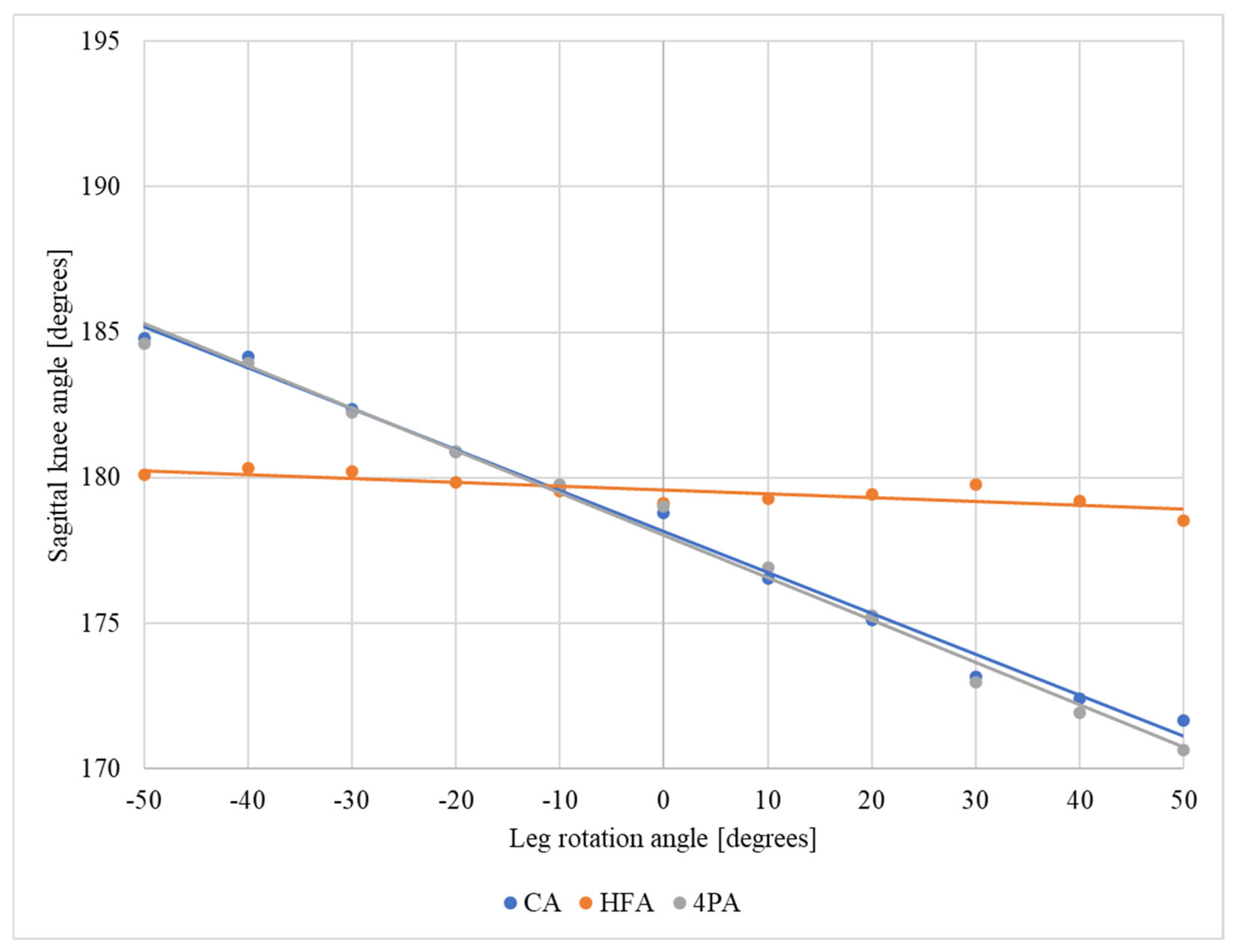
| Protocol | Mean Difference Relative to the Neutral Position—Thigh | Mean Difference Relative to the Neutral Position—Leg | ||
|---|---|---|---|---|
| Internal Rotation | External Rotation | Internal Rotation | External Rotation | |
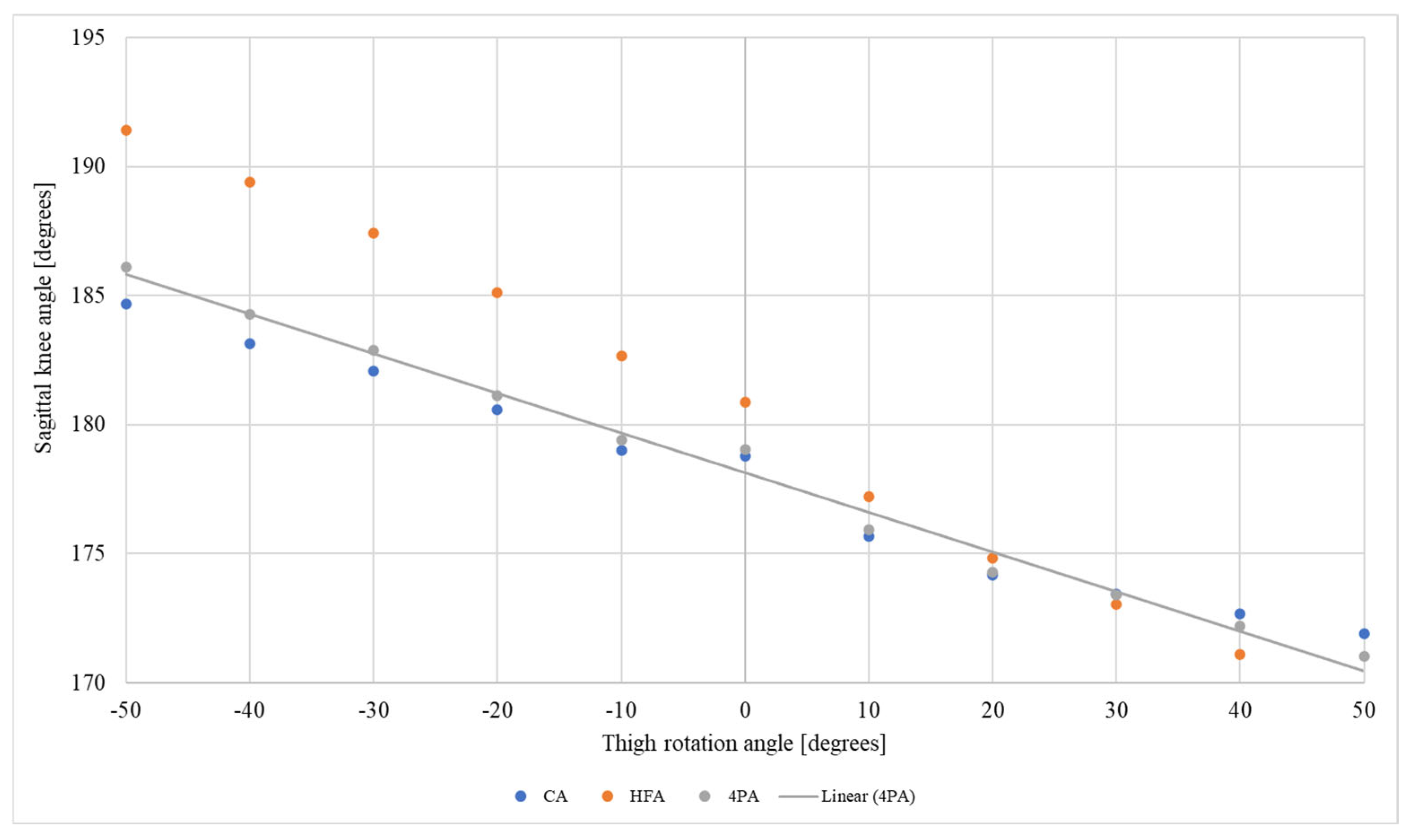
| Condyle angle (CA) | 3.1° | –5.2° | 3.6° | –5° |
| Head of fibula angle (HFA) | 6.3° | –7.8° | 0.9° | 0.1° |
| Four points angle (4PA) | 3.7° | –5.7° | 3.3° | –5.5° |
Disclaimer/Publisher’s Note: The statements, opinions and data contained in all publications are solely those of the individual author(s) and contributor(s) and not of MDPI and/or the editor(s). MDPI and/or the editor(s) disclaim responsibility for any injury to people or property resulting from any ideas, methods, instructions or products referred to in the content. |
© 2025 by the authors. Licensee MDPI, Basel, Switzerland. This article is an open access article distributed under the terms and conditions of the Creative Commons Attribution (CC BY) license (https://creativecommons.org/licenses/by/4.0/).
Share and Cite
da Rosa, B.N.; Wagner Neto, E.S.; Noll, M.; Loss, J.F.; Candotti, C.T. Effects of Thigh and Leg Rotation on Sagittal Knee Angle During Static Assessment. J. Funct. Morphol. Kinesiol. 2025, 10, 235. https://doi.org/10.3390/jfmk10030235
da Rosa BN, Wagner Neto ES, Noll M, Loss JF, Candotti CT. Effects of Thigh and Leg Rotation on Sagittal Knee Angle During Static Assessment. Journal of Functional Morphology and Kinesiology. 2025; 10(3):235. https://doi.org/10.3390/jfmk10030235
Chicago/Turabian Styleda Rosa, Bruna Nichele, Edgar Santiago Wagner Neto, Matias Noll, Jefferson Fagundes Loss, and Cláudia Tarragô Candotti. 2025. "Effects of Thigh and Leg Rotation on Sagittal Knee Angle During Static Assessment" Journal of Functional Morphology and Kinesiology 10, no. 3: 235. https://doi.org/10.3390/jfmk10030235
APA Styleda Rosa, B. N., Wagner Neto, E. S., Noll, M., Loss, J. F., & Candotti, C. T. (2025). Effects of Thigh and Leg Rotation on Sagittal Knee Angle During Static Assessment. Journal of Functional Morphology and Kinesiology, 10(3), 235. https://doi.org/10.3390/jfmk10030235