Enhancing Structural Capacity Assessment with a Novel Failure Decision Function for Rectangular Reinforced Concrete Columns
Abstract
1. Introduction
2. Methods
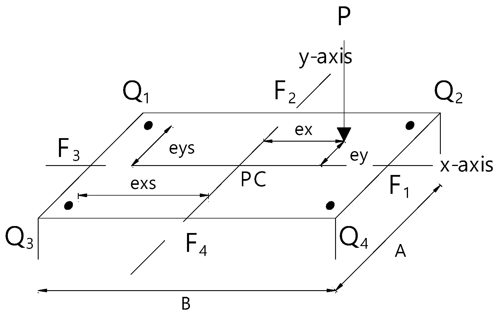
2.1. Model Description and Computational Methodology
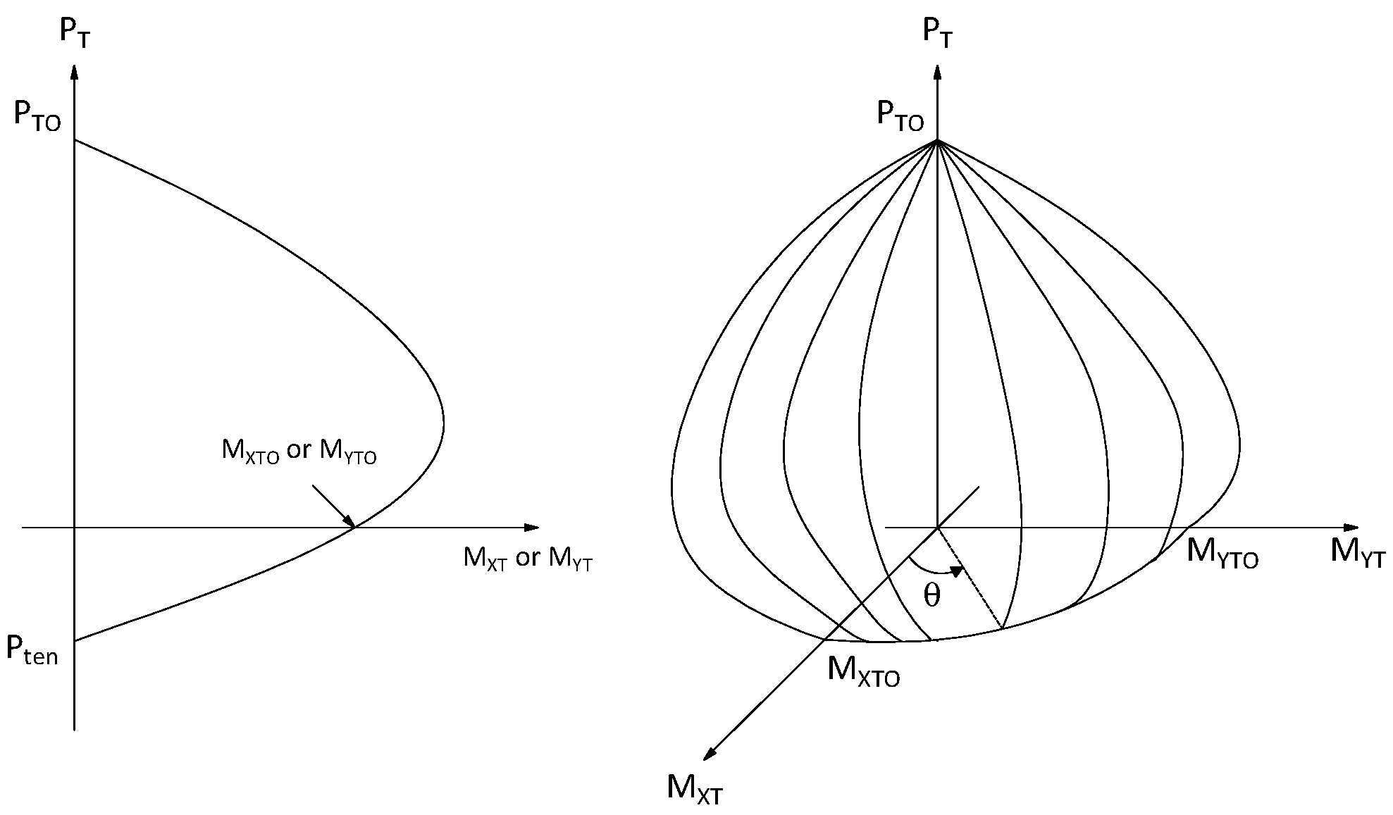
2.2. Generation of the Interaction Diagrams and Failure Surfaces
- 1.
- A lower value for the ultimate load, (Table 1), is calculated using the analytic method. The difference is attributed to the way of the calculation of the ultimate load. Based on examples found in the literature: where is the net area of concrete and is the area of steel reinforcement. While this may be reasonable, it is not consistent with the assumptions regarding the failure of the section, which states that at least one point in the section must reach . However, the stress in concrete is at strain level and not at . At strain level the stress in concrete is resulting in the smaller value of axial force calculated by the analytic method.
- 2.
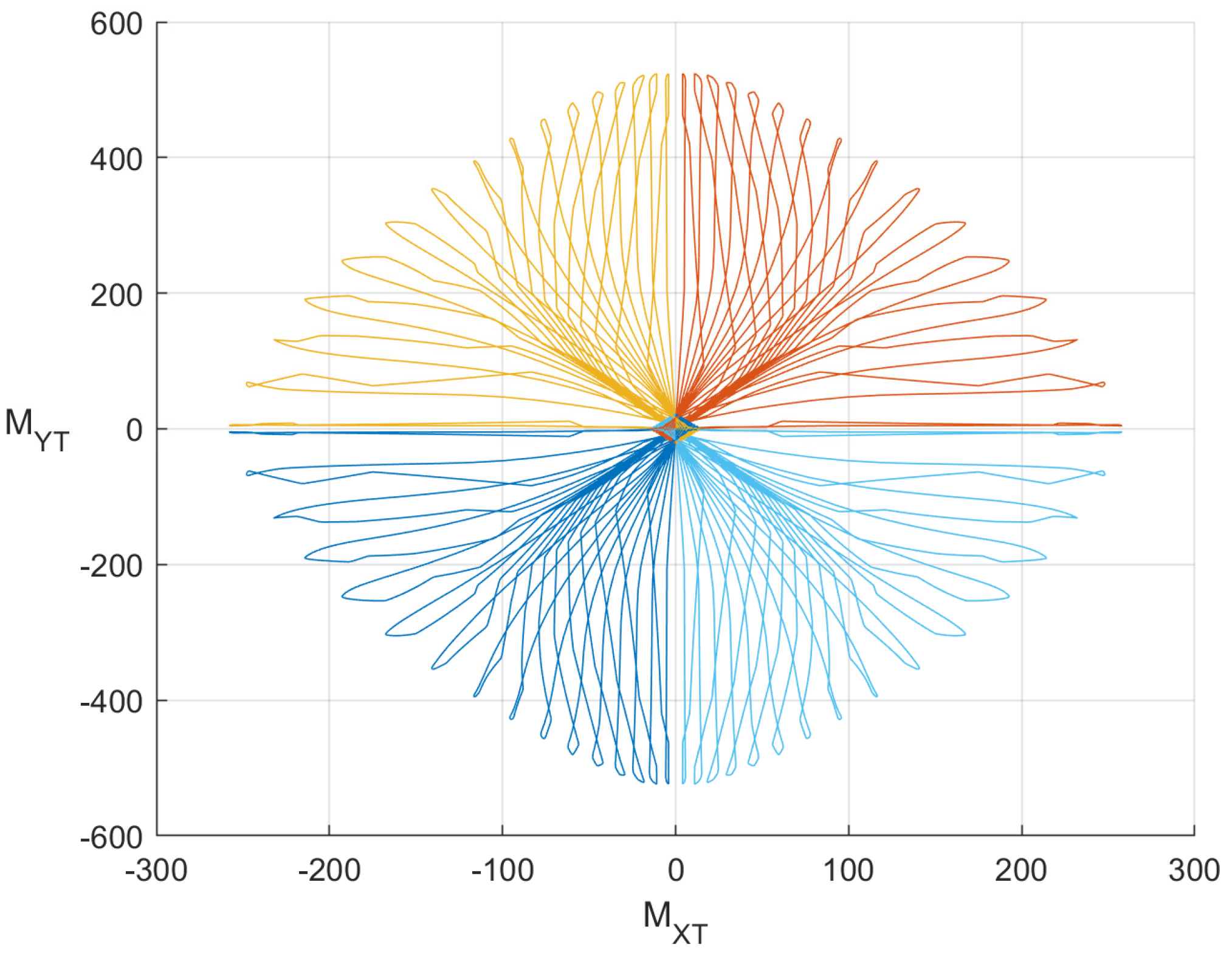
- The curves for various orientations of the NA follow a pattern that is not of planar nature (Figure 6) as shown for typical interaction diagrams found in the literature. The non-planar shape explains why numerical methods sometimes cannot converge to particular points on the interaction diagram.
- 3.
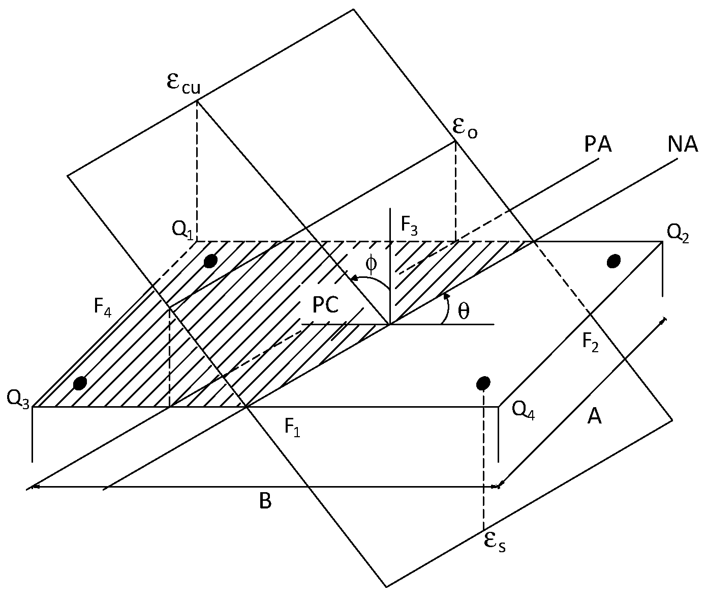
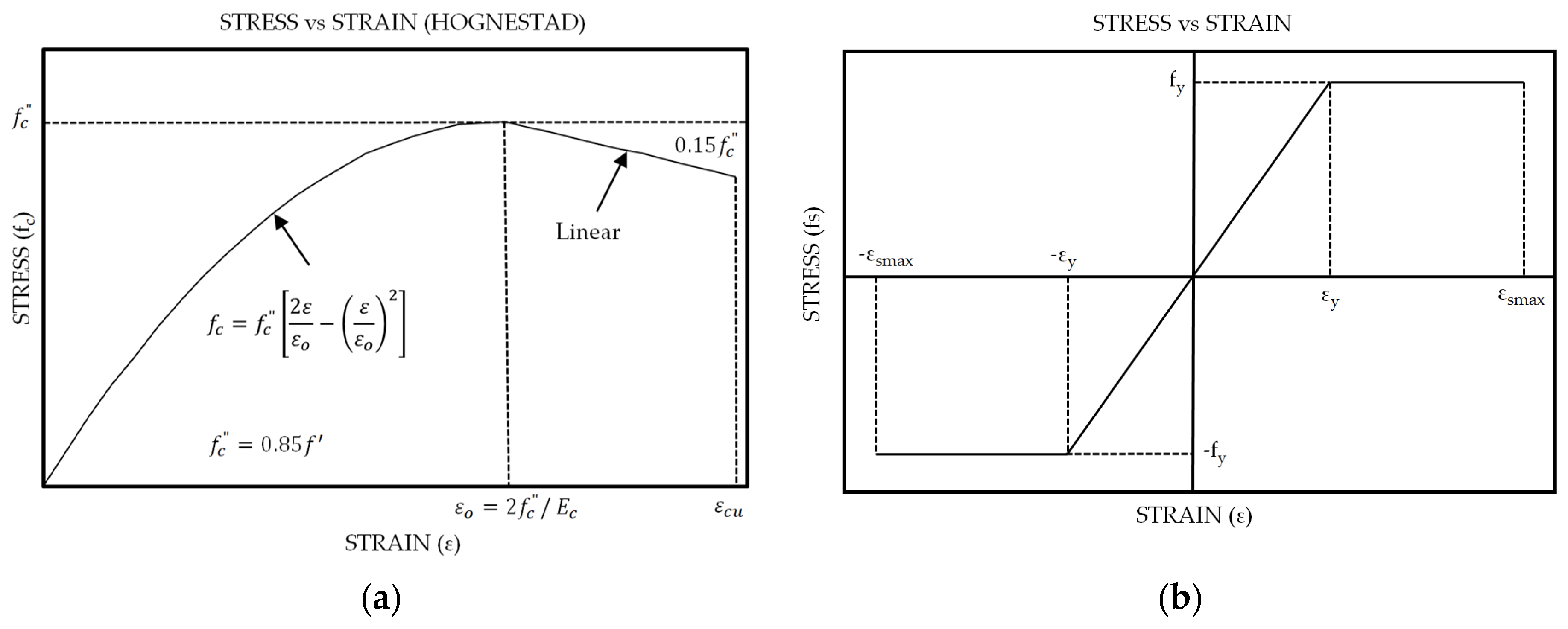
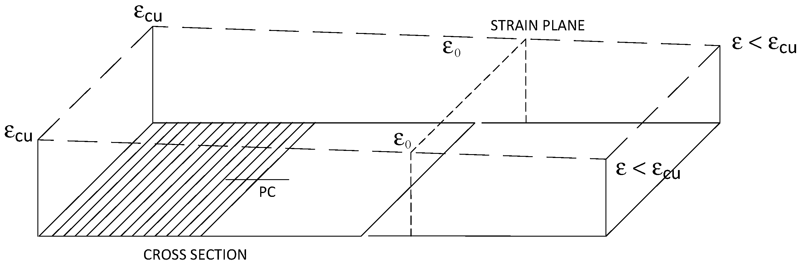
- The upper part of the interaction diagram or the failure surface calculated by the analytic method (Table 1) at strain levels just before the case of pure compression (i.e., when the strain on one side of the section equals to and on the other side is just below as shown in Figure 7 shows that the moments change sign/orientation. When the section is in pure compression, the strain distribution is uniform at the value and the bending moments become zero (assuming that the section is symmetric). Observing the stress–strain relation of concrete (Figure 4a), we note that prior to as the value of the strain increases, so does the value of the stress. However, when the strains are greater than then, as the value of the strain increases, the value of the stress decreases. As the strain plane tends to become horizontal (i.e., state of pure compression,) then all points on the plane have values greater than (Figure 7). Based on the above, the stresses in the shaded area of the section are less than those in the non-shaded area. Considering that the area on both sides of the plastic centroid (shaded and non-shaded) are equal, then the resulting force on the shaded area is less than that of the non-shaded area, causing a moment with opposite sign.
2.3. Failure Decision Function
- a.
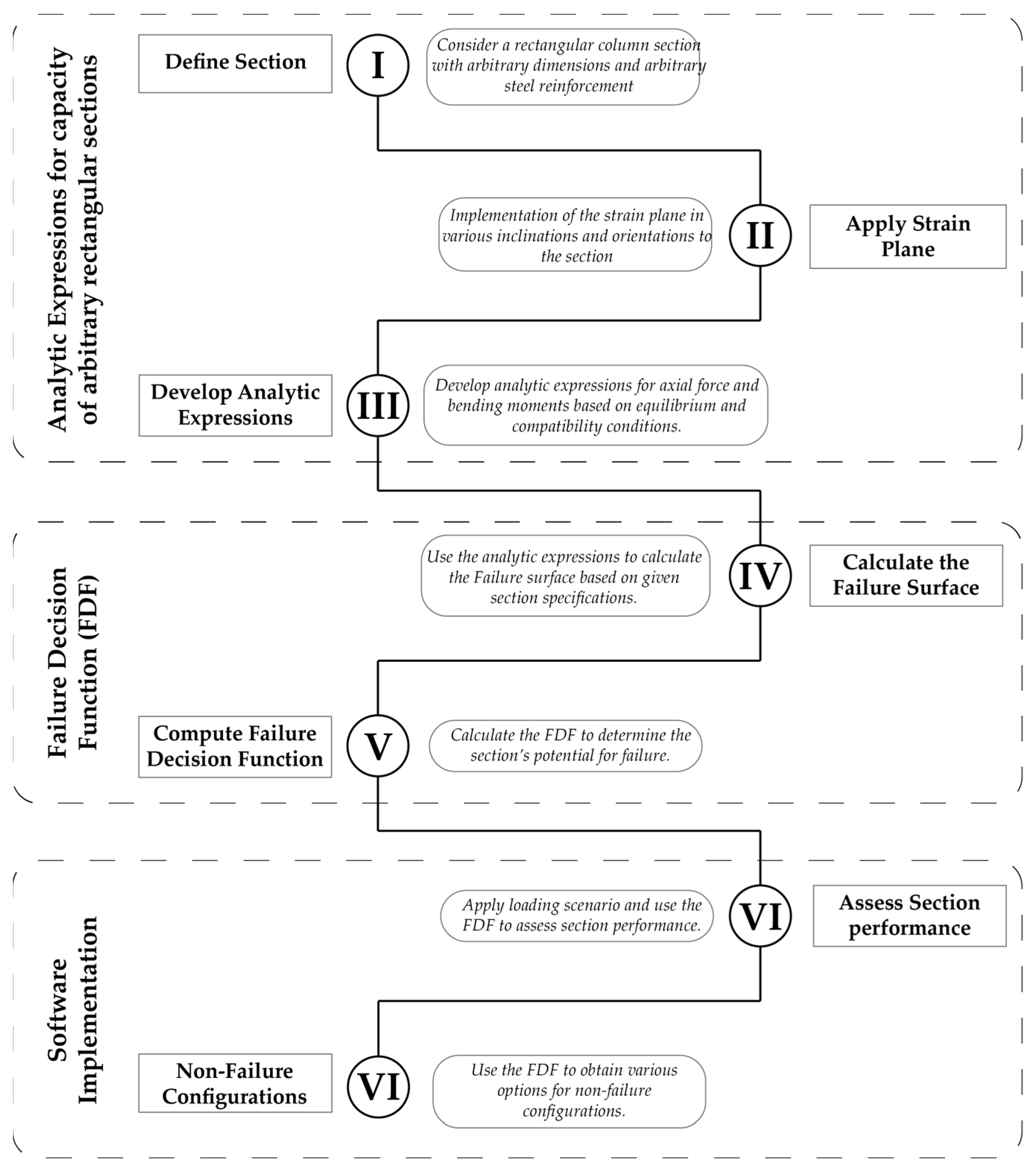
- Setup the model to develop the analytic functions for the computation of the exact shape of the failure surface (Section 2);
- b.
- Generate the failure surface for various types of cross-sections and reinforcement patterns using the analytic functions (Section 3);
- c.
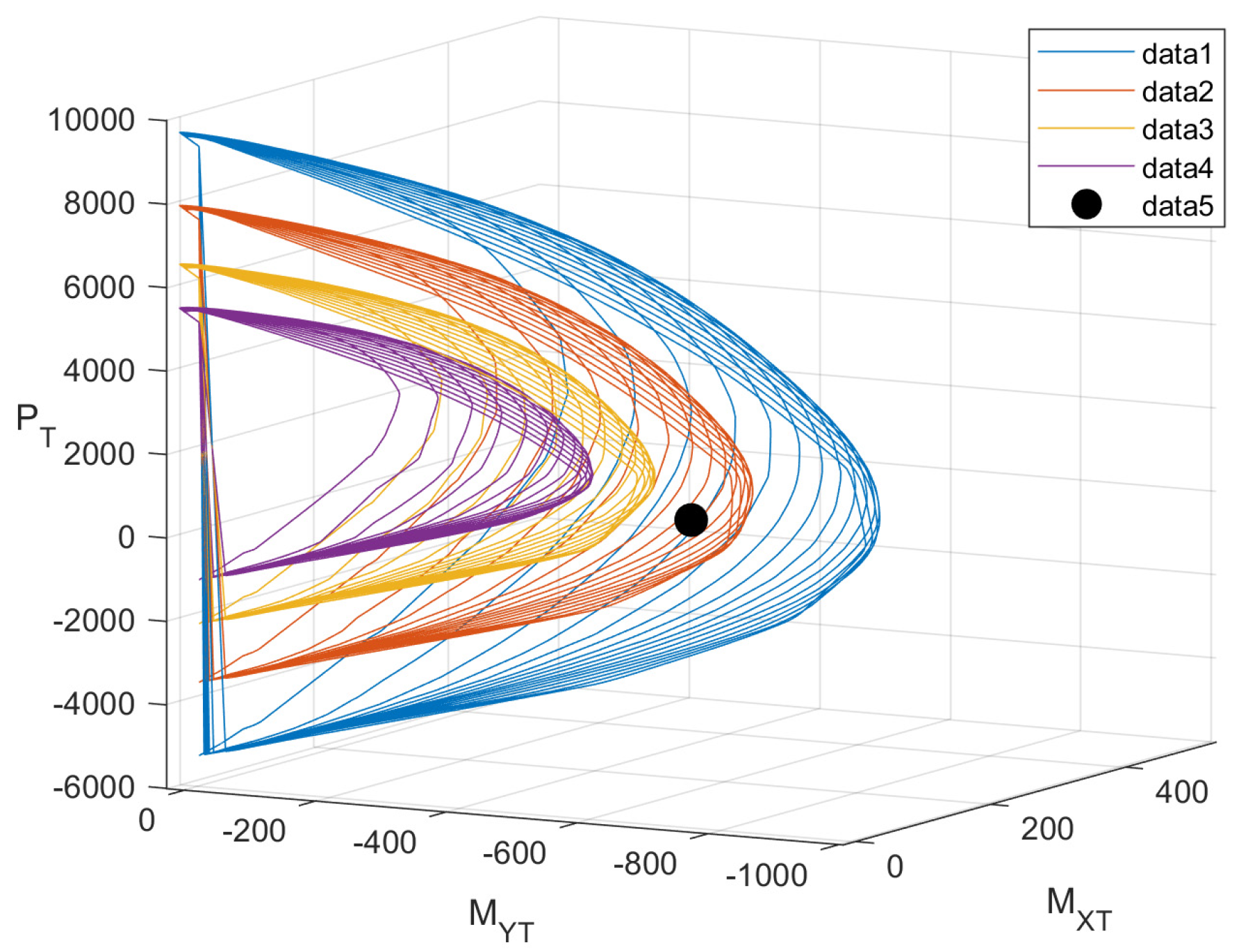
- Develop a polynomial approximation for the failure surface by fitting a surface of the form , through the points of the actual curve. In this work, we utilized the MATLAB optimization toolbox coupled with an test to ensure high accuracy. To ensure that the reduced set of points is well approximated by a smooth function, it is important to approximate each quadrant of angle , of the failure surface separately. Basic reflection and reinforcement rearrangement operations enable the reduction of the approximation problem to fit in the first quadrant. Figure 8 shows a sample of the exact points (in blue) and points obtained by the best-fit polynomial (in red). The R2 approximation index was computed at 0.97, which is considered satisfactory. The high accuracy of the approximation is also reflected in the Figure.
- d.
- Define the Failure Decision Function. Considering that for a particular value of there are multiple-moment couples () the failure surface in any quadrant cannot be expressed in the form of . Rather, one can choose any of the two moments to be approximated as functions of the axial load and the other moment. The simplicity of polynomials, coupled with their significant approximation properties [30], has led the authors to select as a polynomial function of and MXT. Numerical simulations indicate that the choice of moment on the right-hand side does not affect the quality of the approximation. The Failure Decision Function is defined as:
3. Results
Implications to Software
- a.
- Compile a library of Failure Decision Functions, similar to Table 2, in software applications and perform capacity checks without the requirement of developing the failure surfaces, thus saving computational time. Further, include a feature that will enable the software to “suggest” safe cross sections and reinforcement combinations for the applied . The latter will provide the user with the flexibility to experiment with dimensions and reinforcement options prior to running the analysis again.
- b.
- Develop an application that dynamically generates the Failure Decision Function for any specified set of cross-sectional geometries, material properties, and reinforcement patterns. This tool will allow users to “experiment” with different combinations of axial loads and bending moments to evaluate the structural suitability of various sections. The capability to provide instantaneous assessments makes this application particularly valuable in several key engineering activities:
- i.
- Preliminary Design Stage: The application can be utilized to generate trial sections during the initial design phase, enabling designers to quickly iterate over different section configurations. By assessing various combinations of loads and moments, engineers can optimize structural elements efficiently, ensuring that the preliminary designs meet all necessary safety and performance criteria;
- ii.
- Site Inspection: During construction or routine inspections, especially in instances where there are deviations from the initial designs, the application serves as a critical tool for on-the-spot assessments of section capacity. This functionality is crucial for verifying the structural integrity of sections when unexpected changes or errors are detected in the construction phase, thereby aiding in immediate decision-making to address potential safety concerns.
4. Discussion
- Analytic method for constructing uniaxial interaction diagrams and biaxial bending failure surfaces for rectangular reinforced concrete sections. This method utilizes the nonlinear stress–strain relationships for concrete and steel reinforcement to develop precise mathematical expressions;
- Analytic formulae developed within this paper enable the rapid computation of the FDF;
- Failure Decision Function (FDF) is a tool designed to assess the structural integrity of columns subjected to axial forces and either uniaxial or biaxial bending moments.
5. Conclusions
Supplementary Materials
Author Contributions
Funding
Data Availability Statement
Conflicts of Interest
References
- Grasser, E.; Linse, D. Bemessungstafeln für Stahlbetonquerschnitte Auf der Grundlage der Neuen DIN 1045; Werner Verlag: Düsseldorf, Germany, 1972. [Google Scholar]
- Duţulescu, E. Näherungsverfahren bei zweiachsiger Biegung mit Normalkraft. Beton-Stahlbetonbau 2015, 110, 254–269. [Google Scholar] [CrossRef]
- Nilson, A.H.; Winter, G. Design of Concrete Structures, 11th ed.; McGraw-Hill Inc.: New York, NY, USA, 1991; Available online: https://www.amazon.co.uk/Design-Concrete-Structures-Arthur-Nilson/dp/0070465673 (accessed on 23 May 2024).
- Papanikolaou, V.K.; Sextos, A.G. Design charts for rectangular R/C columns under biaxial bending: A historical review toward a Eurocode-2 compliant update. Eng. Struct. 2016, 115, 196–206. [Google Scholar] [CrossRef]
- Kolapkar, B.N.; Balakrishnan, B.; Menon, D. Biaxial bending of RC rectangular column sections: Improved ‘load contour’ formulation. Struct. Concr. 2023. [Google Scholar] [CrossRef]
- Dundar, C.; Tokgoz, S.; Tanrikulu, A.K.; Baran, T. Behaviour of reinforced and concrete-encased composite columns subjected to biaxial bending and axial load. Build. Environ. 2008, 43, 1109–1120. [Google Scholar] [CrossRef]
- Pallarés, L.; Bonet, J.L.; Miguel, P.F.; Fernández Prada, M.A. Experimental research on high strength concrete slender columns subjected to compression and biaxial bending forces. Eng. Struct. 2008, 30, 1879–1894. [Google Scholar] [CrossRef]
- Fafitis, A. Interaction Surfaces of Reinforced Concrete Sections in Biaxial Bending by Green’s Theorem. In Proceedings of the 8th International Conference on Computing in Civil and Building, Stanford, CA, USA, 14–16 August 2000. [Google Scholar] [CrossRef]
- Papanikolaou, V.K. Analysis of arbitrary composite sections in biaxial bending and axial load. Comput. Struct. 2012, 98–99, 33–54. [Google Scholar] [CrossRef]
- Matuszak, A.; Pluciński, P. Accuracy of Cross-Section Stress Numerical Integration by Boundary Integration Formulae; CRC Press eBooks: Boca Raton, FL, USA, 2014; pp. 111–120. [Google Scholar] [CrossRef]
- Lejano, B. Investigation of Biaxial Bending of Reinforced Concrete Columns through Fiber Method Modeling. Available online: https://www.sefindia.org/forum/files/column_126.pdf (accessed on 10 April 2024).
- Christou, P.; Michael, A.; Anastasiou, C.; Nicolaides, D. Effect of confinement on the interaction diagrams for rc sections with cfrp grids and wraps. Int. J. Comput. Methods Exp. Meas. (Print) 2013, 1, 265–282. [Google Scholar] [CrossRef]
- Kwak, H.-G.; Kwak, J.-H. An improved design formula for a biaxially loaded slender RC column. Eng. Struct. 2010, 32, 226–237. [Google Scholar] [CrossRef]
- Bouzid, T.; Demagh, K. Practical method for analysis and design of slender reinforced concrete columns subjected to biaxial bending and axial loads. Slovak J. Civ. Eng. 2011, XIX, 24–32. [Google Scholar] [CrossRef]
- Di Laora, R.; Galasso, C.; Mylonakis, G.; Cosenza, E. A simple method for N-M interaction diagrams of circular reinforced concrete cross sections. Struct. Concr. 2019, 21, 48–55. [Google Scholar] [CrossRef]
- Rodriguez, J.A.; Aristizabal-Ochoa, J.D. Biaxial Interaction Diagrams for Short RC Columns of Any Cross Section. J. Struct. Eng. 1999, 125, 672–683. [Google Scholar] [CrossRef]
- Quaranta, G.; Trentadue, F.; Marano, G.C. Closed-form approximation of the axial force-bending moment interaction diagram for hollow circular reinforced concrete cross-sections. Eng. Struct. 2017, 153, 516–524. [Google Scholar] [CrossRef]
- Vaz Rodrigues, R. A new technique for ultimate limit state design of arbitrary shape RC sections under biaxial bending. Eng. Struct. 2015, 104, 1–17. [Google Scholar] [CrossRef]
- Shustin, P.F.; Avron, H. Gauss-Legendre Features for Gaussian Process Regression. arXiv 2021, arXiv:2101.01137. [Google Scholar] [CrossRef]
- da Silva, V.D.; Barros, M.H.F.M.; Julio, E.N.B.S.; Ferreira, C.C. Closed form ultimate strength of multi-rectangle reinforced concrete sections under axial load and biaxial bending. Comput. Concr. 2009, 6, 505–521. [Google Scholar] [CrossRef]
- Schneider, P.; Eberly, D.H. Geometric Tools for Computer Graphics; Elsevier: Amsterdam, The Netherlands, 2002. [Google Scholar]
- Panjehpour, M.; Chai, H.K.; Voo, Y.L. Refinement of Strut-and-Tie Model for Reinforced Concrete Deep Beams. PLoS ONE 2015, 10, e0130734. [Google Scholar] [CrossRef] [PubMed][Green Version]
- Numerical and Analytical Modeling of Concrete Confined with FRP Wraps. Available online: https://etda.libraries.psu.edu/files/final_submissions/10784 (accessed on 12 April 2024).
- Michael, A.; Hamilton, H.R. Experimental ductility of compression-controlled flexural members using CFRP grid to confine concrete. Materials 2021, 14, 5163. [Google Scholar] [CrossRef] [PubMed]
- Oztekin, E.; Pul, S.; Husem, M. Determination of rectangular stress block parameters for high performance concrete. Eng. Struct. 2003, 25, 371–376. [Google Scholar] [CrossRef]
- Park, R.; Paulay, T. Ultimate Deformation and Ductility of Members with Flexure. In Reinforced Concrete Structures; John Wiley & Sons: Hoboken, NJ, USA, 1975; pp. 195–269. [Google Scholar] [CrossRef]
- MathWorks MATLAB—MathWorks. Mathworks.com. 2019. Available online: https://www.mathworks.com/products/matlab.html (accessed on 10 April 2024).
- Leet, K.; Bernal, D. Reinforced Concrete Design; McGraw-Hill Companies: New York, NY, USA, 1997. [Google Scholar]
- Wang, C.K.; Salmon, C.G. Reinforced Concrete Design. trid.trb.org. 1979. Available online: https://trid.trb.org/view/502701 (accessed on 23 May 2024).
- Heiberger, R.M.; Neuwirth, E. Polynomial Regression. In R through Excel; Springer: New York, NY, USA, 2009; pp. 269–284. [Google Scholar] [CrossRef]

| AA | Cross Section | Interaction Diagram | Failure Decision Function |
|---|---|---|---|
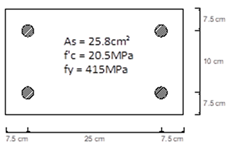
| A | Example 7.7—Leet and Bernal (1997) | 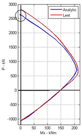 | 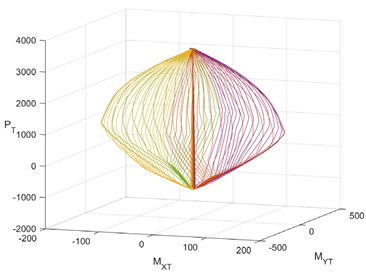 |
 | |||
| B | Example 13.14.1—Wang and Salmon (1979) | 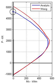 | 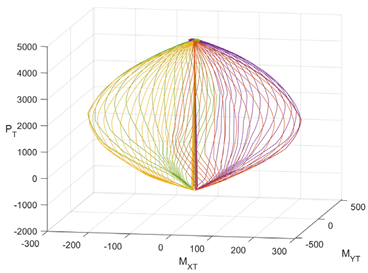 |
 | |||
| C | Example 8.1—Nilson and Winter (1991) |  | 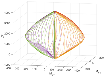 |
 |
| AA | Section | Failure Decision Function |
|---|---|---|
| A | Example 7.7—Leet and Bernal (1997)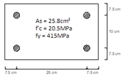 |
|
| B | Example 13.14.1—Wang and Salmon (1979) |
|
| C | Example 8.1—Nilson and Winter (1991) |
|
| D | Section 50 cm × 50 cm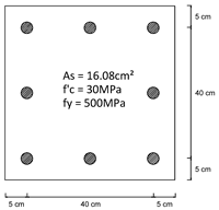 |
|
| E | Section 40 cm × 40 cm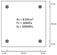 |
|
| A | ny | B | nx | FDF | A | ny | B | nx | FDF |
|---|---|---|---|---|---|---|---|---|---|
| 0.3 | 2 | 0.5 | 5 | F | 0.4 | 2 | 0.6 | 2 | F |
| 0.3 | 3 | 0.5 | 5 | F | 0.5 | 5 | 0.4 | 4 | P |
| 0.3 | 2 | 0.6 | 2 | F | 0.4 | 3 | 0.6 | 2 | F |
| 0.3 | 3 | 0.6 | 2 | F | 0.4 | 4 | 0.6 | 2 | F |
| 0.3 | 2 | 0.6 | 3 | F | 0.4 | 2 | 0.6 | 3 | F |
| 0.4 | 4 | 0.5 | 3 | F | 0.4 | 3 | 0.6 | 3 | F |
| 0.4 | 2 | 0.5 | 4 | F | 0.4 | 4 | 0.6 | 3 | P |
| 0.4 | 3 | 0.5 | 4 | F | 0.4 | 2 | 0.6 | 4 | F |
| 0.4 | 4 | 0.5 | 4 | P | 0.4 | 3 | 0.6 | 4 | P |
| 0.4 | 2 | 0.5 | 5 | F | 0.4 | 4 | 0.6 | 4 | P |
| 0.4 | 3 | 0.5 | 5 | P | 0.5 | 2 | 0.5 | 2 | F |
| 0.4 | 4 | 0.5 | 5 | P | 0.5 | 3 | 0.5 | 2 | F |
Disclaimer/Publisher’s Note: The statements, opinions and data contained in all publications are solely those of the individual author(s) and contributor(s) and not of MDPI and/or the editor(s). MDPI and/or the editor(s) disclaim responsibility for any injury to people or property resulting from any ideas, methods, instructions or products referred to in the content. |
© 2024 by the authors. Licensee MDPI, Basel, Switzerland. This article is an open access article distributed under the terms and conditions of the Creative Commons Attribution (CC BY) license (https://creativecommons.org/licenses/by/4.0/).
Share and Cite
Christou, P.; Charalambides, M.; Nicolaides, D.; Xekalakis, G. Enhancing Structural Capacity Assessment with a Novel Failure Decision Function for Rectangular Reinforced Concrete Columns. Inventions 2024, 9, 63. https://doi.org/10.3390/inventions9030063
Christou P, Charalambides M, Nicolaides D, Xekalakis G. Enhancing Structural Capacity Assessment with a Novel Failure Decision Function for Rectangular Reinforced Concrete Columns. Inventions. 2024; 9(3):63. https://doi.org/10.3390/inventions9030063
Chicago/Turabian StyleChristou, Petros, Marios Charalambides, Demetris Nicolaides, and Georgios Xekalakis. 2024. "Enhancing Structural Capacity Assessment with a Novel Failure Decision Function for Rectangular Reinforced Concrete Columns" Inventions 9, no. 3: 63. https://doi.org/10.3390/inventions9030063
APA StyleChristou, P., Charalambides, M., Nicolaides, D., & Xekalakis, G. (2024). Enhancing Structural Capacity Assessment with a Novel Failure Decision Function for Rectangular Reinforced Concrete Columns. Inventions, 9(3), 63. https://doi.org/10.3390/inventions9030063


