Article

Invention of a Medical Glove Durability Assessment Device

1
Department of Food, Agricultural, and Biological Engineering, The Ohio State University, Columbus, OH 43210, USA
2
Center for Design and Manufacturing Excellence, The Ohio State University, Columbus, OH 43210, USA
3
Department of Horticulture and Crop Science, The Ohio State University, Columbus, OH 43210, USA
4
EnergyEne Inc., Wooster, OH 44691, USA
*
Author to whom correspondence should be addressed.
Inventions 2022, 7(3), 62; https://doi.org/10.3390/inventions7030062
Submission received: 7 June 2022 / Revised: 12 July 2022 / Accepted: 18 July 2022 / Published: 22 July 2022
(This article belongs to the Section Inventions and Innovation in Biotechnology and Materials)

Abstract

:
Healthcare workers across the globe rely on medical gloves to prevent the transfer of harmful bacteria and viruses between themselves and their patients. Unfortunately, due to the lack of an in-use durability standard for medical gloves by the American Society for Testing and Materials, many of these gloves are of low quality and are easily torn or punctured, exposing wearers and patients to potentially deadly diseases. To solve this problem, a device that automatically detects material failures the size of a pinhole during active testing was invented. The device consists of a prosthetic hand, vacuum pump, mobile textured roller, pressure sensor, and liquid spray system. It works by creating a vacuum inside the glove and repeatedly moving the textured roller into contact with the fingertips, which, on the prosthetic hand, are porous. When a glove perforates, the vacuum is broken, pressure within the hand rapidly increases, and the operator is alerted on a touchscreen that the glove has failed. In addition, the liquid spray system allows the user to test gloves in “real world” conditions, because healthcare workers often come into contact with liquids that may alter glove durability. As a preliminary test of the device’s accuracy, five nitrile and five latex exam gloves were tested using the system’s default settings. Natural latex is known to be the highest performing glove material, so the nitrile gloves were expected to fail more quickly than the latex gloves. The test results concur with this expected order of failure: nitrile first, with an average failure time of 300 s and 42 average number of roller touches, followed by natural latex, with an average failure time of 2206 s and 300 average number of roller touches. These results provide evidence that the device accurately ranks glove durability, and therefore could be used to develop an ASTM durability standard and improve the quality of gloves made from different polymers.

1. Introduction

Medical gloves are an essential piece of personal protective equipment (PPE) because they act as a protective barrier, preventing the transfer of bacteria, viruses, and toxins from healthcare worker to patient and vice versa. With the emergence and spread of COVID-19 in early 2020, the demand for medical gloves doubled, resulting in many healthcare facilities facing a shortage of these necessary supplies [1,2]. Despite the important role of gloves in disease prevention, the American Society for Testing and Materials (ASTM) standards for rubber surgical gloves (D3577-19) and rubber examination gloves (D3578-19) lack a specification for in-use glove durability once the gloves are removed from their packaging by the consumer [3,4]. Manufacturing and polymer differences mean that some types of gloves are more prone to breakage under stress than others. Unfortunately, the current ASTM standard for the detection of holes in medical gloves only measures the incidence of gloves with holes before their actual use, and this protocol entails merely filling a glove with tap water and observing it for leaks [5].
The need for a standardized medical glove assessment device is most evident when natural and synthetic gloves are compared. A 2011 study in which natural latex and latex-free gloves were examined for perforations following surgical use found that latex was perforated only 34.3% of the time, compared to 80% for synthetic polyisoprene [6]. An additional study in which gloves of a variety of materials made by different manufacturers were perforated using a standardized procedure found that bacterial passage through medical examination gloves occurred at a 10-fold higher rate in nitrile and neoprene gloves compared to natural latex [7]. In addition, the size of the hole left in the glove after a needle stick puncture was smaller in natural latex films than in nitrile films [8]. These results demonstrate that not all gloves provide the same level of protection, and that a uniform durability standard would ensure that all gloves provide a minimum level of protection regardless of material or manufacturer.
The combination of high glove demand and lack of a durability standard led to our development of a medical glove durability assessment machine. The device closely simulates real-world glove use because a glove is placed on a prosthetic hand, which comes into repeated contact with a roughened surface until a hole is detected in the glove. This device could ensure that all gloves meet a basic standard of durability while being worn and forms the basis for a new ASTM standard for medical and surgical glove durability.

2. Materials and Methods

2.1. Capstone Glove Assessment Device (C-GAD)

The glove testing prototype previously described [9] was modified in collaboration with the Center for Design and Manufacturing Excellence (CDME) at the Ohio State University, Columbus, Ohio, USA, due to expired software. Although the basic components of the C-GAD remained the same, an ESP32 Expressif Systems microcontroller (Expressif, Shanghai, China) with a Nextion Touch Display LED (light emitting diode) touchscreen (Nextion, Shenzhen, China) was wired to the motor for improved ease of use. The touchscreen displayed the elapsed time, test number, speed, and force of the motor. The hand was also attached to an aluminum rail structure, and the entire system was mounted on a piece of plywood for added stability (Figure 1). The major drawback of this design was the need to visually inspect the gloves for holes, which entailed frequent inspection stoppages and approximately a 5 s or more delay in break detection [6]. Therefore, a new iteration of this glove testing device was designed, with the goal of increasing precision of glove failure data, improving ease of use, and making a machined version which could be readily manufactured.

2.2. New Glove Assessment Device (N-GAD)

2.2.1. Touchscreen Display

The N-GAD was designed to automatically detect holes in medical gloves, eliminating the need for manual glove inspection. Like the C-GAD, the N-GAD also utilizes an ESP32 Expressif Systems microcontroller and a Nextion Touch Display LED touchscreen (Appendix A), however, the N-GAD was designed with increased functionality. The homepage of the LED touchscreen (Figure 2) displays the number of touches completed, the speed of the drum movement in mm/s, the force of the drum in mN, and the number of sprays between touches, and all settings are adjustable (Table 1 and Table 2).
The depressurization failure page appears on the touchscreen if the machine cannot depressurize before a test has begun (Figure 3). This screen has only one text field and one button (Table 3 and Table 4).
The test page appears after the glove has successfully been depressurized and the drum has begun to move. It displays the current elapsed time as well as the touch number that the machine is currently executing (Figure 4). It should be noted that the elapsed time is paused during the process of depressurization. A test can be aborted at any time by pressing the “Abort” button. Otherwise, the machine automatically switches to the “test complete” page once the glove has failed (Table 5 and Table 6).
The test abort page is displayed after the “Abort” button has been selected (Figure 5). There are no buttons on this page, as its purpose is to inhibit user input until the machine has returned to the pre-test configuration (Table 7). The most time-consuming part of that process is the movement of the drum into the home position. Once the machine returns to the pre-test configuration, the display automatically switches to the home page.
The glove failure page is displayed when a pressure differential is detected by the sensor, indicating that the glove has been punctured. The elapsed time and number of touches are paused so that the user can note them down (Figure 6). Pressing the “Okay” button returns the user to the homepage (Table 8 and Table 9).
When the number of touches reaches the pre-set value without the glove failing, the “test complete” page is displayed (Figure 7). The elapsed time is paused so that the user can note it down. The machine returns to the home page when the “Okay” button is pressed (Table 10 and Table 11).

2.2.2. System Design

Figure 8 shows a conceptual drawing of the basic components of the device. Notably, the new system is encased in plexiglass and contains a pump and reservoir system for testing gloves in wet conditions with various solvents. Another notable difference from the C-GAD is the stationary prosthetic hand and mobile drum. This design choice was made to allow the prosthetic hand to be easily interchanged with other prosthetic hands of various sizes.
In general, the device works by removing the air from within the base of the prosthetic hand via a vacuum pump after the hand is fitted with a glove. The textured drum then moves into position and comes into contact with the porous fingertips of the hand until a tear occurs in the glove. When this happens, a pressure differential is sensed by a pressure sensor located within the base of the hand, and the device stops, thereby eliminating manual inspection.

2.2.3. Hand and Vacuum Pump

For this prototype, a plastic prosthetic hand was 3D printed using the dimensions of an average adult male’s hand [10]. To improve the ease of glove application, the hand was designed without a thumb (Figure 9). The fingertips of the hand are sintered polyethylene mufflers, which contain intricate networks of open-celled, omni-directional pores that allow for airflow. After being applied to the hand, the glove is held in place with a silicone O-ring, and air is removed from within the base via a 12/24 VDC vacuum pump with a 2-way isolation/exhaust valve (Figure 9). However, when a puncture occurs in the glove, the air is free to flow through the porous fingertips, causing a positive pressure differential that is detected by an Adafruit pressure sensor located within the base of the hand (Figure 9). Prior to installation, the pressure sensor was manually calibrated to ensure accurate results.

2.2.4. Drum Motion

The plastic wedge-shaped drum was designed for easy application of sandpaper, which was held in place using two clamps, one on either end of the drum (Figure 10). A stepper motor controlled the movement of the drum by applying a horizontal force to an attached metal rod. The force caused the drum to pivot around a center pin, creating perpendicular contact with the fingertips of the hand. In order to control the force with which the drum contacts the hand, an in-line 10 kg load cell was calibrated using a second load cell and installed on the same rod that is moved by the stepper motor (Figure 10). Both the stepper motor and the load cell were electronically wired to the control center (Figure 11).

2.2.5. Liquid System

The liquid system allows the user to test the durability of medical gloves after the gloves are exposed to various solvents. The hand, drum, and spray nozzles were encased in a plexiglass testing chamber to keep the liquid contained during testing. The two spray nozzles were aligned to point at the fingertips of the hand (Figure 10a). The reservoirs were placed within the base of the device, and they consisted of two large plastic bottles with lids containing tubing that connect to either the pump or the liquid-collection pan (Figure 12). A 12/24 VDC peristaltic pump was chosen for the liquid system, and it was connected to the control system so that the user can adjust the number of liquid sprays between touches (Figure 12). The liquid stream was designed to leave the nozzle as a “drip” rather than a spray. This design choice was made to ensure user safety when performing tests with liquids that are toxic when aerosolized, such as ethanol.
In the final assembly of the device, the pumps and reservoir system are located underneath the testing chamber, and the electronic components are located behind the touchscreen to the left of the testing chamber (Figure 13). A complete list of replaceable parts is found in Appendix A. The specifications for the power supply, stepper motor, and pressure are found in Appendix B.

2.3. Experimental Design

The accuracy of the NGTD was verified by comparing the failure rates of two different exam glove types: nitrile and latex. A previous study found that the failure times of these two glove types were significantly different from each other, with nitrile having the statistically shorter failure time [11]. Thus, if the NGTD produced failure times that were consistent with these results, the device could be assumed to be accurate. For each trial, the selected glove was carefully placed onto the prosthetic hand through the lid at the top of the testing chamber. The two clamps on either end of the semicircular drum were loosened and a strip of 120-grit sandpaper was clamped in place, one end at a time.
The settings on the touchscreen remained at their default values (Table 12). If a glove did not fail by the end of the 50 touches, the time and number of touches were recorded, and a new test was run. When the glove did fail, the values for elapsed time and number of touches were totaled and recorded. After failure, the glove was removed from the hand and discarded along with the sandpaper. A new glove and piece of sandpaper were used for each trial.

3. Results and Discussion

A one-way analysis of variance test was performed for glove material versus time and glove material versus number of touches (Table 13 and Table 14). Both of the analyses show that nitrile gloves break more easily than natural latex gloves (p = 0.0029 and p = 0.0031, respectively). Average failure times and average number of touches to failure are represented visually as a bar graph (Figure 14). It should be noted that the time and number of touches to failure data for latex has a large variation due to manufacturing inconsistencies, which further supports the need for a universal glove durability standard. The order of glove failure, nitrile followed by latex, concurs with the results of previous studies, and provides evidence that the N-GAD’s measurements are accurate [11].
The rise in prevalence of synthetic gloves, especially in the examination glove market, was due to the widespread incidence of Type I latex allergies in the 1990s caused by sensitizing levels of soluble proteins in natural latex gloves. These proteins resulted from a manufacturing failure due to the rapid increase in glove demand in response to the AIDS epidemic. Many new manufacturers sprang up in southeast Asia, and their inexperience led to the elimination of the in-line glove washing process that had previously been the norm. Afterall, latex gloves look exactly the same whether washed or unwashed. After only a few exposures to unbleached high protein gloves, a patient can develop a permanent Type I latex allergy. However, since this manufacturing failure was characterized and found to be the cause of the Type I latex allergy “epidemic”, reputable manufacturers reinstated the inline washing process, and natural latex gloves again became safe for those not previously sensitized by high protein products. Only a few products remain still with high protein levels, such as some brands of dental dams [12]. When an unwashed dental dam is placed inside a patient’s mouth, the soluble proteins are extracted by saliva in sufficient quantity to sometimes induce sensitization, and certainly enough to cause an allergic reaction in a previously sensitized person [12].
Since medical workers may not be aware of the significant disparity in glove quality, implementing a post-packaging durability assessment as a standard part of the glove manufacturing quality assurance process will ensure that all medical gloves meet a minimum level of durability, protecting the consumer from low-quality gloves. Investing in high-quality gloves may also save healthcare facilities thousands of dollars per year on more expensive life-saving resources. In other words, higher quality PPE protects more people from diseases and hospitalization, can save lives, and reduce medical malpractice claims.
Finally, as the name suggests, natural latex is produced naturally by plants such as Hevea brasiliensis, or the Brazilian rubber tree. Plant-based materials are desirable because they are more environmentally sustainable than synthetic materials, which are synthesized from petroleum. Unlike natural latex products, synthetic rubber products are not biodegradable and contribute to the pollution of the environment. The rise in demand due to COVID-19 has also increased interest in alternative natural latex sources, such as Parthenium argentatum (guayule) and Taraxacum kok-saghyz (rubber dandelion). Guayule latex films outperform all other known natural and synthetic latices, including glove durability [11], puncture size [8], contain very little protein, and have no proteins which cross react with Type I latex allergy [13]. Rubber dandelion latex appears more similar to rubber tree latex and does contain cross-reactive proteins [14]. The introduction of new natural latices makes our device even more relevant to the medical glove industry and their customers.

4. Conclusions

The key findings of this study are as follows:
  • The average failure time for nitrile gloves was 300 s, and the average number of roller touches to failure was 42 touches.
  • The average failure time for latex gloves was 2206 s, and the average number of roller touches to failure was 300 touches.
  • One-way ANOVA tests showed that nitrile failure time and number of touches to failure were significantly different from latex failure time and number of touches to failure (p = 0.0029 and p = 0.0031, respectively).
  • The order of glove failure, nitrile followed by latex, concurs with the results of previous studies, and provides evidence that the N-GAD’s measurements are accurate.
Healthcare workers rely on medical gloves for protection against potentially deadly bacteria, viruses, and toxins, but the gloves they use may not actually be providing the level of protection they expect. The medical glove durability assessment device discussed in this paper has the potential to standardize the quality of medical gloves, no matter the material or manufacturer. Regardless of whether the glove is made of synthetic or natural materials, glove manufacturers have a responsibility to produce high-quality gloves with consistent in-use durability. Therefore, future work will include collecting failure data for a wider variety of natural and synthetic gloves produced by different manufacturers and presenting the N-GAD to ASTM as a solution to the lack of durability standard.

Author Contributions

Conceptualization, A.V., M.P., W.V., Y.W. and K.C.; methodology, A.V., M.P., W.V., Y.W. and K.C.; software, Y.W.; validation, A.V.; formal analysis, A.V.; investigation, A.V.; data curation, A.V.; writing—original draft preparation, A.V.; writing—review and editing, K.C.; funding acquisition, K.C. All authors have read and agreed to the published version of the manuscript.
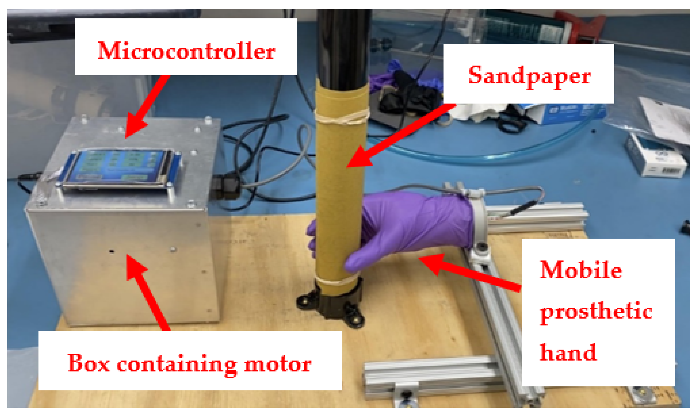
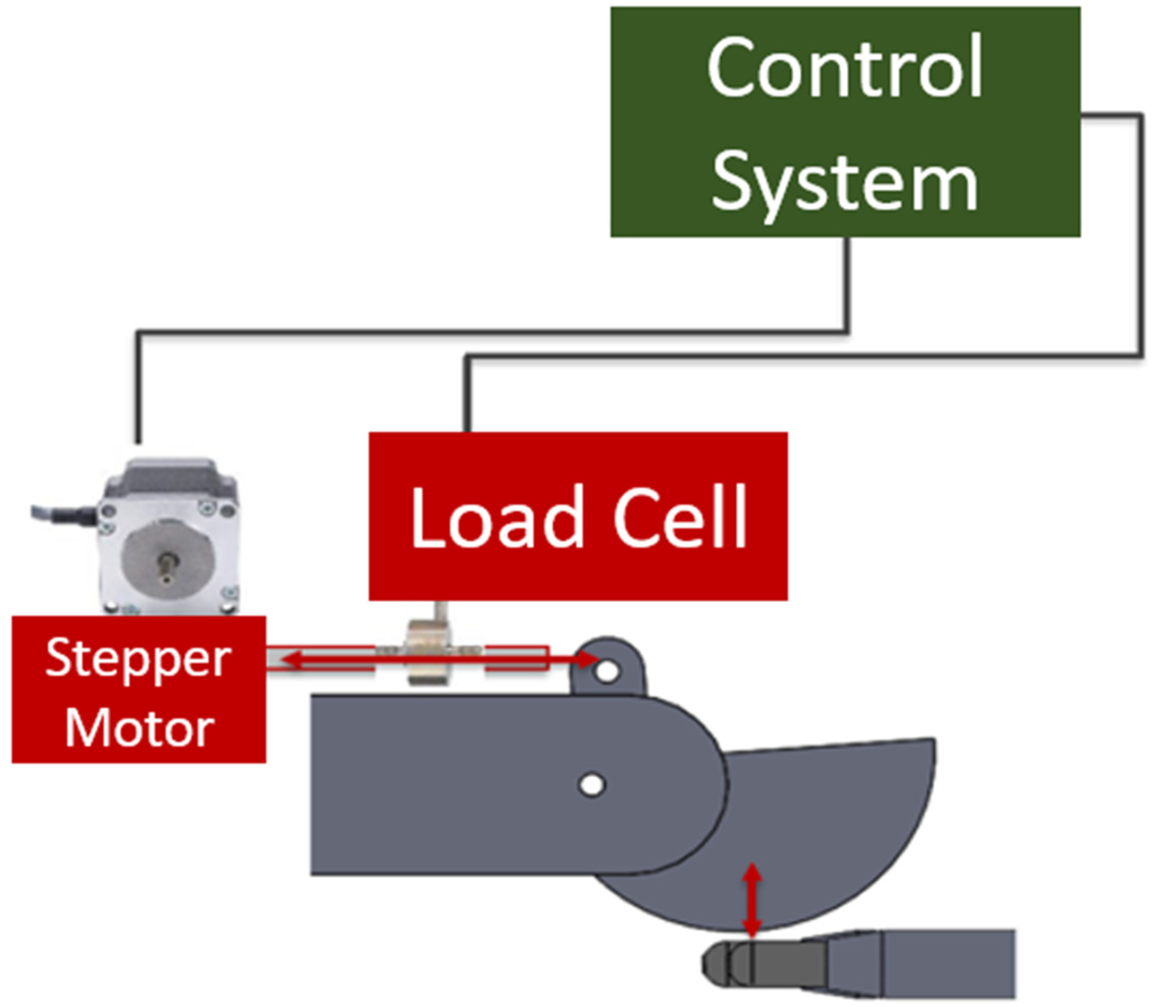
Funding

This research was funded by the USDA SBIR Phase II awarded to EnergyEne Inc., grant number 1024332.

Institutional Review Board Statement

Not applicable.

Informed Consent Statement

Not applicable.

Data Availability Statement

Not applicable.

Acknowledgments

This work was made possible through the USDA-NIFA Hatch Project OHO01417 and the engineers and students at the OSU Center for Design and Manufacturing Excellence.

Conflicts of Interest

The authors declare no conflict of interest.

Appendix A

Table A1. List of replaceable parts for the N-GAD.
ItemDescriptionSupplierPart Number
Liquid PumpPeristaltic PumpSimply PumpsPMP200
Vacuum PumpMini Vacuum Pump, 5 L/min, 12 V DCAmazon753,874,419,842
ValvesStainless Steel Solenoid Valve, 12 V DC, 1/8 NPTMcMaster-Carr5077T114
MotorStep Motor Hybrid Linear Actuator, 12 V DCDigi-Key1568-1189-ND
Load CellMini Tension and Compression Load Cell, 0–10 kgAmazonDYMH-103
Pressure SensorMPRLS Ported Pressure Sensor, 0–25 PSIAdafruit3965
SandpaperWater Resistant Sanding SheetsMcMaster-Carr6835A48
O-ringsSoft Silicone O-ring, 1/8, Dash Number 245McMaster-Carr1173N484
O-ringsSoft Silicone O-ring, 1/4, Dash Number 411McMaster-Carr1173N607
O-ringsSoft Silicone O-ring, 1/4, Dash Number 412McMaster-Carr1173N608
O-ringsSoft Silicone O-ring, 1/4, Dash Number 413McMaster-Carr1173N609
O-ringsSoft Silicone O-ring, 1/4, Dash Number 414McMaster-Carr1173N611
FingertipsNPT Male Polyethylene Plastic FittingMcMaster-Carr4427K82
LED ScreenNextion Touch DisplayMouser713–104,990,604
StylusLCD Touch Panels StylusMouser817-N010-0557-T011

Appendix B

Table A2. Power supply characteristics.
TypicalMaximum Range
Input Voltage *120 VAC or 230 VAC85–132 VAC or 170–264 VAC
Input Current0.2 A0.1 A–1.0 A
Fuse5 A, 250 V fast blow glass fuse
* Overvoltage category III protection.
Table A3. Stepper motor characteristics.
Maximum SpeedMaximum Force
10 mm/s45 N
Table A4. Pressure characteristics.
Depressurization TargetWorking RangeTypical Depressurization Time
40 MPa40–80 MPa23 s

References

  1. Market Research Reports. Available online: https://www.researchandmarkets.com/reports/5403544/medical-gloves-market-global-outlook-and?utm_source=BW&%3Butm_medium=PressRelease&%3Butm_code=mbrq64&%3Butm_campaign=1578882%2B-%2BGlobal%2B%2418.56%2BBn%2BMedical%2BGloves%2BMarket%2BOutlook%2B%26%2BForecast%2Bto%2B2026%2Bwith%2BCOVID-19%2BImplication%2BAnalysis&%3Butm_exec=chdo54prd (accessed on 11 April 2022).
  2. U.S. Food and Drug Administration. Medical Device Shortages During the COVID-19 Public Health Emergency. Available online: https://www.fda.gov/medical-devices/coronavirus-covid-19-and-medical-devices/medical-device-shortages-during-covid-19-public-health-emergency (accessed on 11 April 2022).
  3. D3577-19; Standard Specification for Rubber Surgical Gloves. ASTM International: West Conshohocken, PA, USA, 2019.
  4. D3578-19; Standard Specification for Rubber Examination Gloves. ASTM International: West Conshohocken, PA, USA, 2019.
  5. D5151-19; Standard Test Method for Detection of Holes in Medical Gloves. ASTM International: West Conshohocken, PA, USA, 2019.
  6. Thomas, S.; Aldlyami, E.; Gupta, S.; Reed, M.R.; Muller, S.D.; Partington, P.F. Unsuitability and high perforation rate of latex-free gloves in Arthroplasty: A cause for concern. Arch. Orthop. Trauma Surg. 2010, 131, 455–458. [Google Scholar] [CrossRef] [PubMed]
  7. Bardorf, M.H.; Jäger, B.; Boeckmans, E.; Kramer, A.; Assadian, O. Influence of material properties on gloves’ bacterial barrier efficacy in the presence of microperforation. Am. J. Infect. Control. 2016, 44, 1645–1649. [Google Scholar] [CrossRef] [PubMed]
  8. Cornish, K.; Brichta, J.L.; Yu, P.; Wood, D.F.; McGlothlin, M.W.; Martin, J.A. Guayule latex provides a solution for the critical demands of the non-allergenic medical products market. Agro-Food-Ind. Hi-Tech 2001, 12, 27–31. [Google Scholar]
  9. Michel, R.; Cornish, K. Comparative Durability and Abrasion Resistance of Natural and Synthetic Latex Gloves. In Proceedings of the International Latex Conference, Fairlawn, OH, USA, 11–12 August 2015; pp. 1–18. Available online: https://www.rubbernews.com/assets/PDF/RN10078185.PDF (accessed on 12 April 2022).
  10. NASA. 3 ANTHROPOMETRY AND BIOMECHANICS. Available online: https://msis.jsc.nasa.gov/sections/section03.htm (accessed on 11 April 2022).
  11. Michel, R.; Cornish, K. Comparing Natural, Synthetic Latex Gloves. Rubber Plast. News 2016, 10–13. Available online: https://s3-prod.rubbernews.com/s3fs-public/RN10326818.PDF (accessed on 12 April 2022).
  12. Cornish, K.; Bates, G.M.; Slutzky, J.L.; Meleshchuk, A.; Xie, W.; Sellers, K.; Mathias, R.; Boyd, M.; Castaneda, R.; Wright, M.; et al. Extractable protein levels in latex products and their associated risks, emphasizing American dentistry. Biol. Med. 2019, 11, 2. [Google Scholar] [CrossRef] [Green Version]
  13. Cornish, K. Assessment of the risk of Type I latex allergy sensitization or reaction during use of products made from latex derived from guayule and other alternate rubber producing species. Rubber Sci. 2012, 25, 139–155. [Google Scholar]
  14. Cornish, K.; Xie, W.; Kostyal, D.; Shintani, D.; Hamilton, R.G. Immunological analysis of the alternate natural rubber crop Taraxacum kok-saghyz indicates multiple proteins cross-reactive with Hevea brasiliensis latex allergens. J. Biotechnol. Biomater. 2015, 5, 201–207. [Google Scholar] [CrossRef]
Figure 1. Modified setup of the original glove testing device.
Inventions 07 00062 g001
Figure 2. Homepage of LED touchscreen.
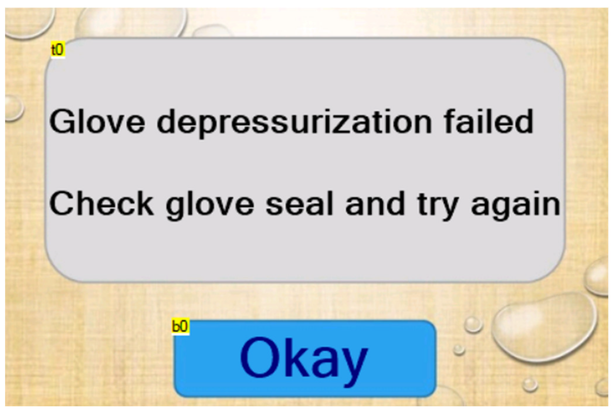
Inventions 07 00062 g002
Figure 3. Depressurization failure page.
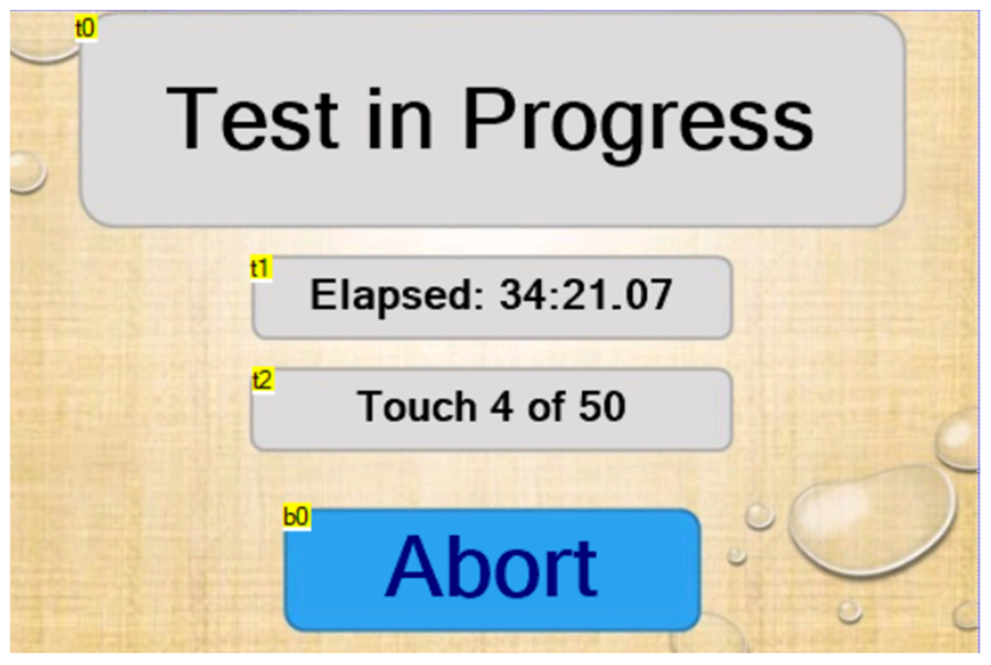
Inventions 07 00062 g003
Figure 4. Test page as it appears during a test.
Inventions 07 00062 g004
Figure 5. Test abort page.
Inventions 07 00062 g005
Figure 6. Glove failure page with paused elapsed time and touch number.
Inventions 07 00062 g006
Figure 7. “Test complete” page.
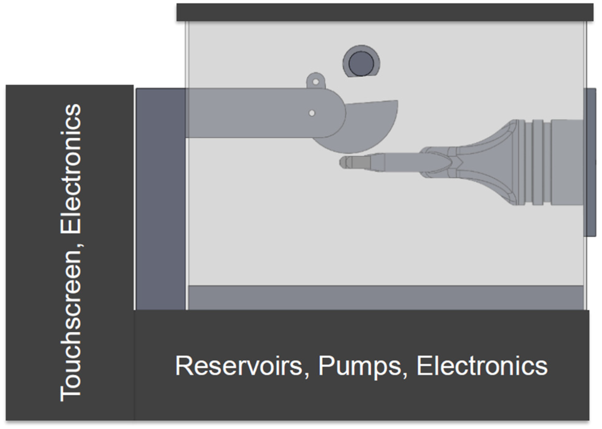
Inventions 07 00062 g007
Figure 8. Conceptual AutoCAD model of the new glove testing device.
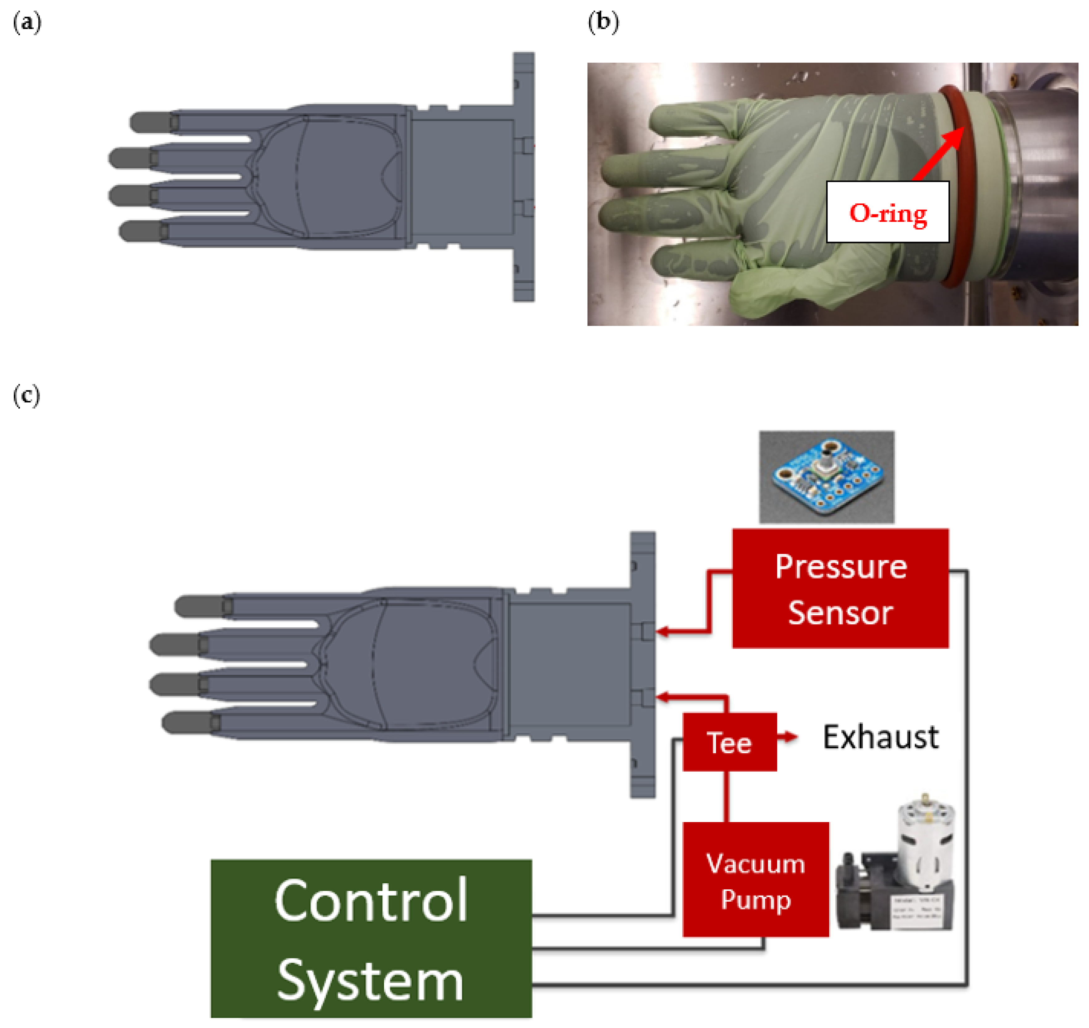
Inventions 07 00062 g008
Figure 9. (a) AutoCAD model of 3D printed prosthetic hand. (b) Silicone O-ring applied to the base of the prosthetic hand. (c) Diagram of the connections between the prosthetic hand, vacuum pump, pressure sensor, and control system.
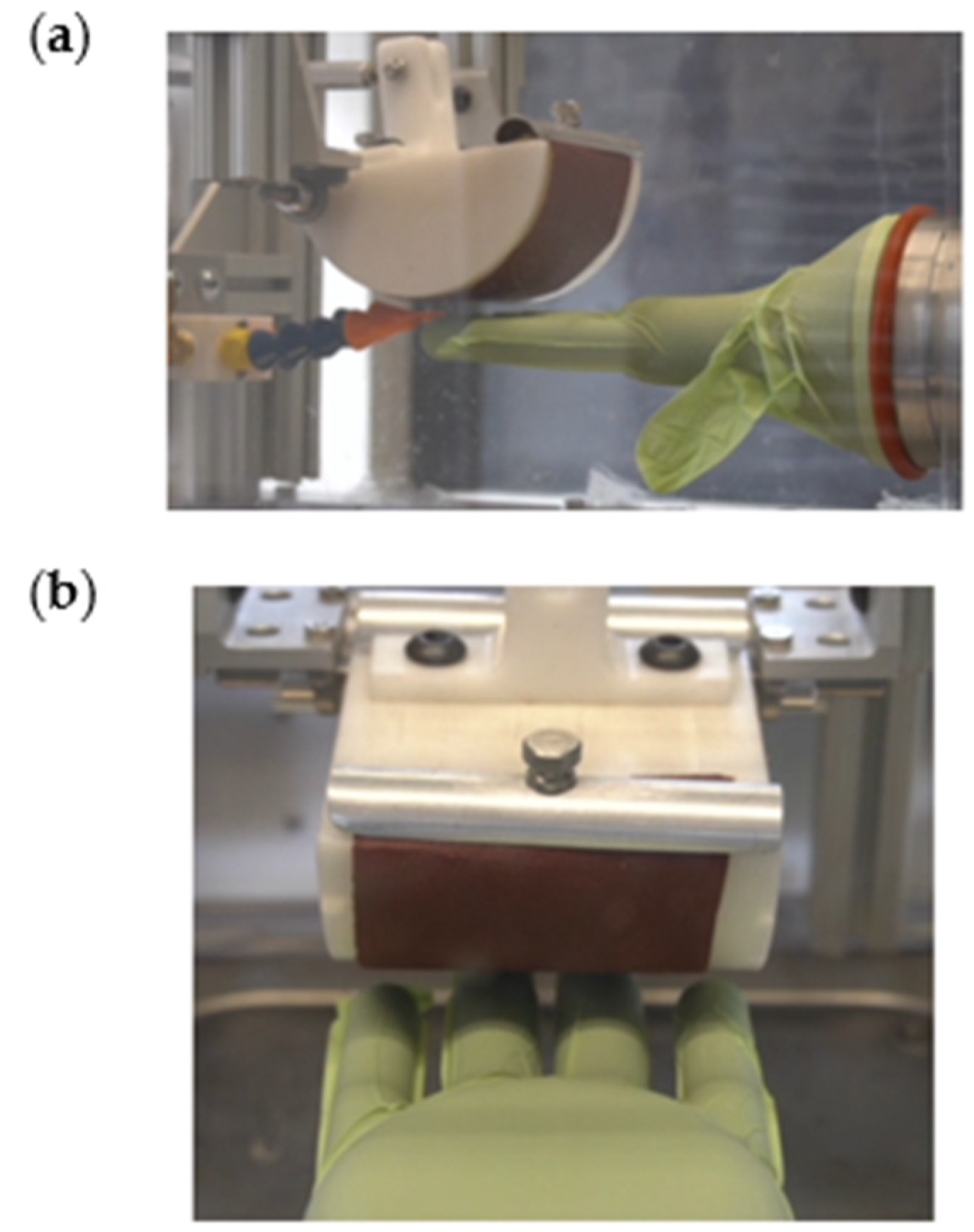
Inventions 07 00062 g009
Figure 10. (a) Side view of drum with sandpaper and clamps, and (b) top view of drum with sandpaper and clamps.
Inventions 07 00062 g010
Figure 11. Diagram of the connections between the drum, motor, and control system.
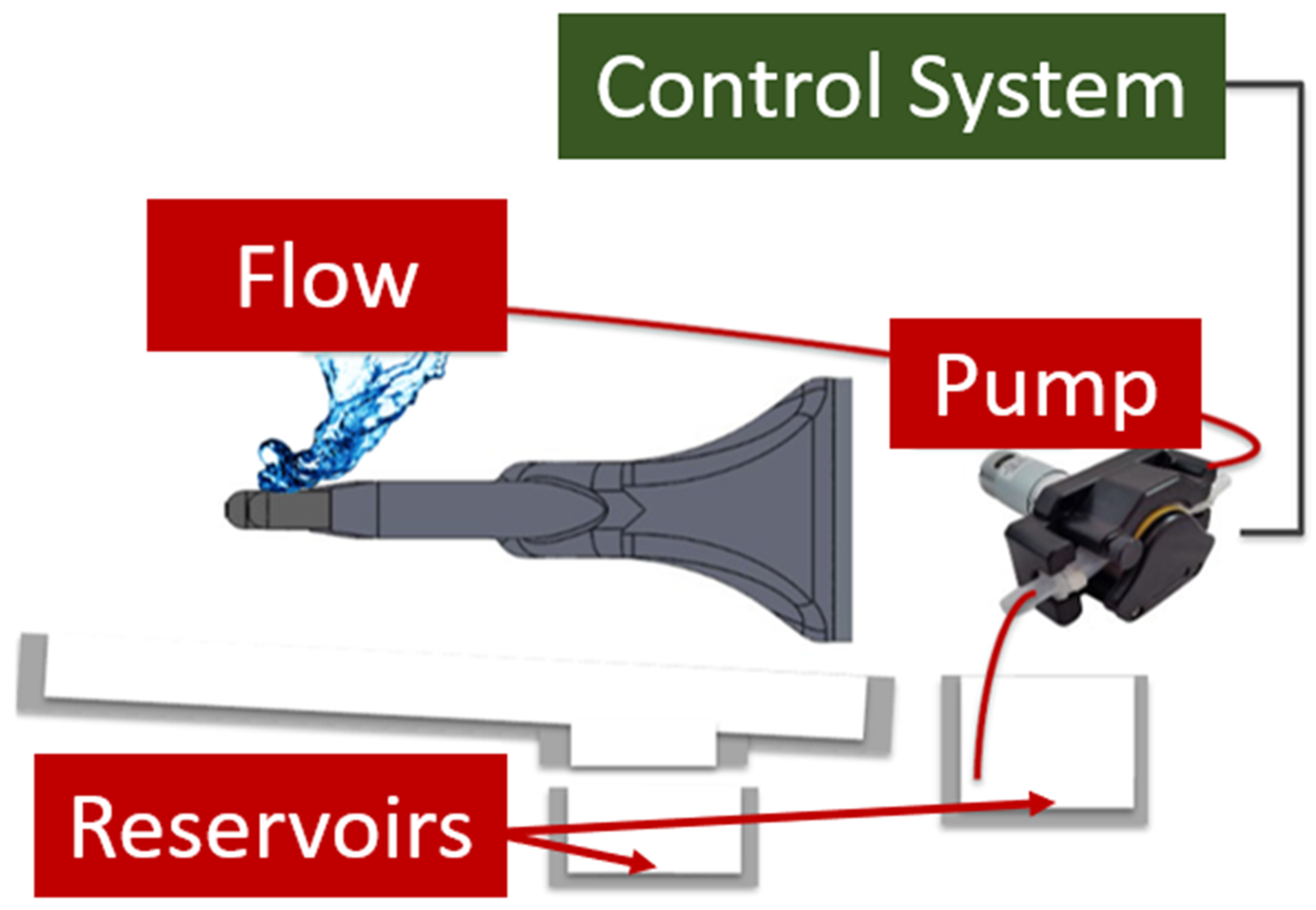
Inventions 07 00062 g011
Figure 12. Diagram of the connections between the hand, liquid pump, and control system.
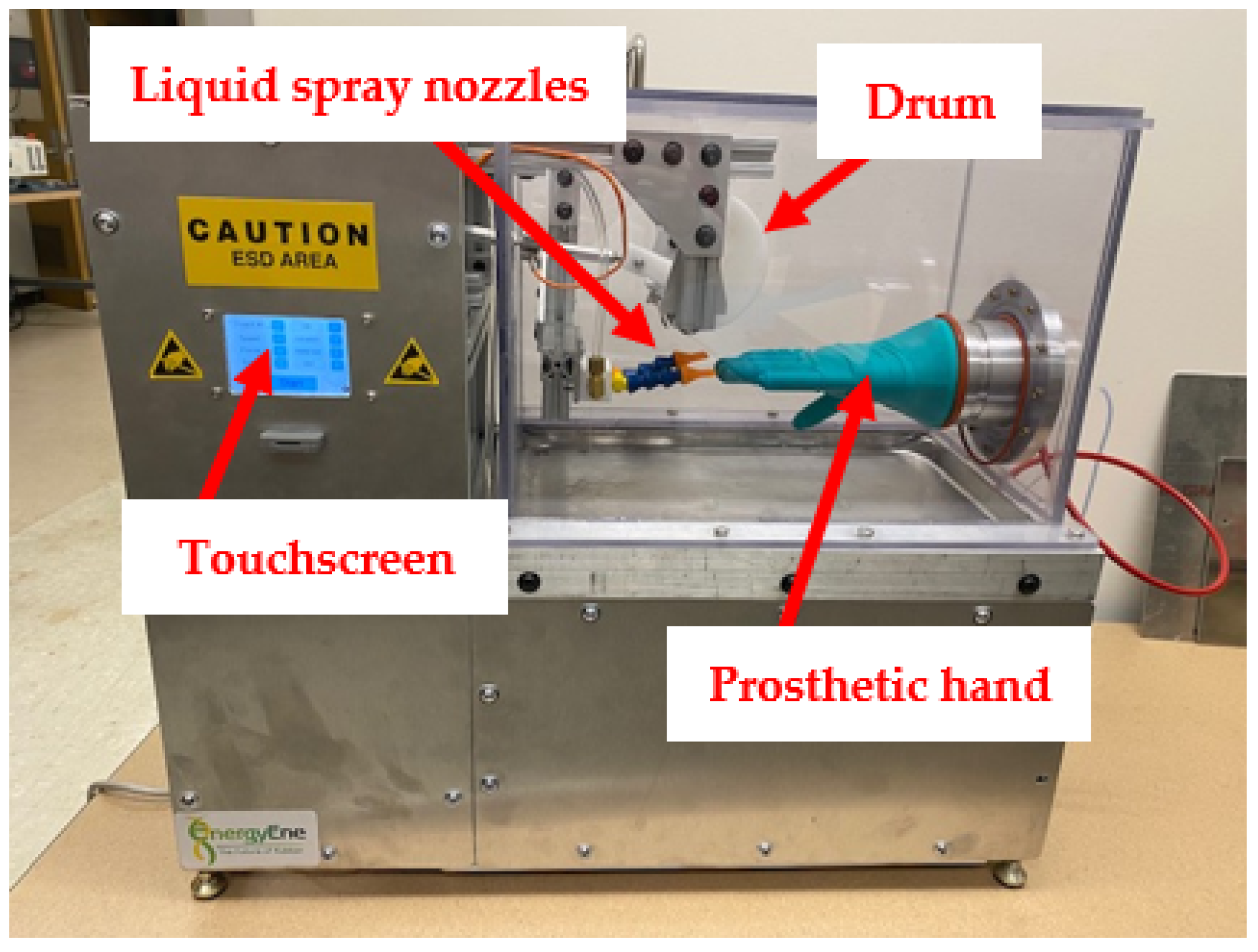
Inventions 07 00062 g012
Figure 13. Final assembly of the new glove testing device.
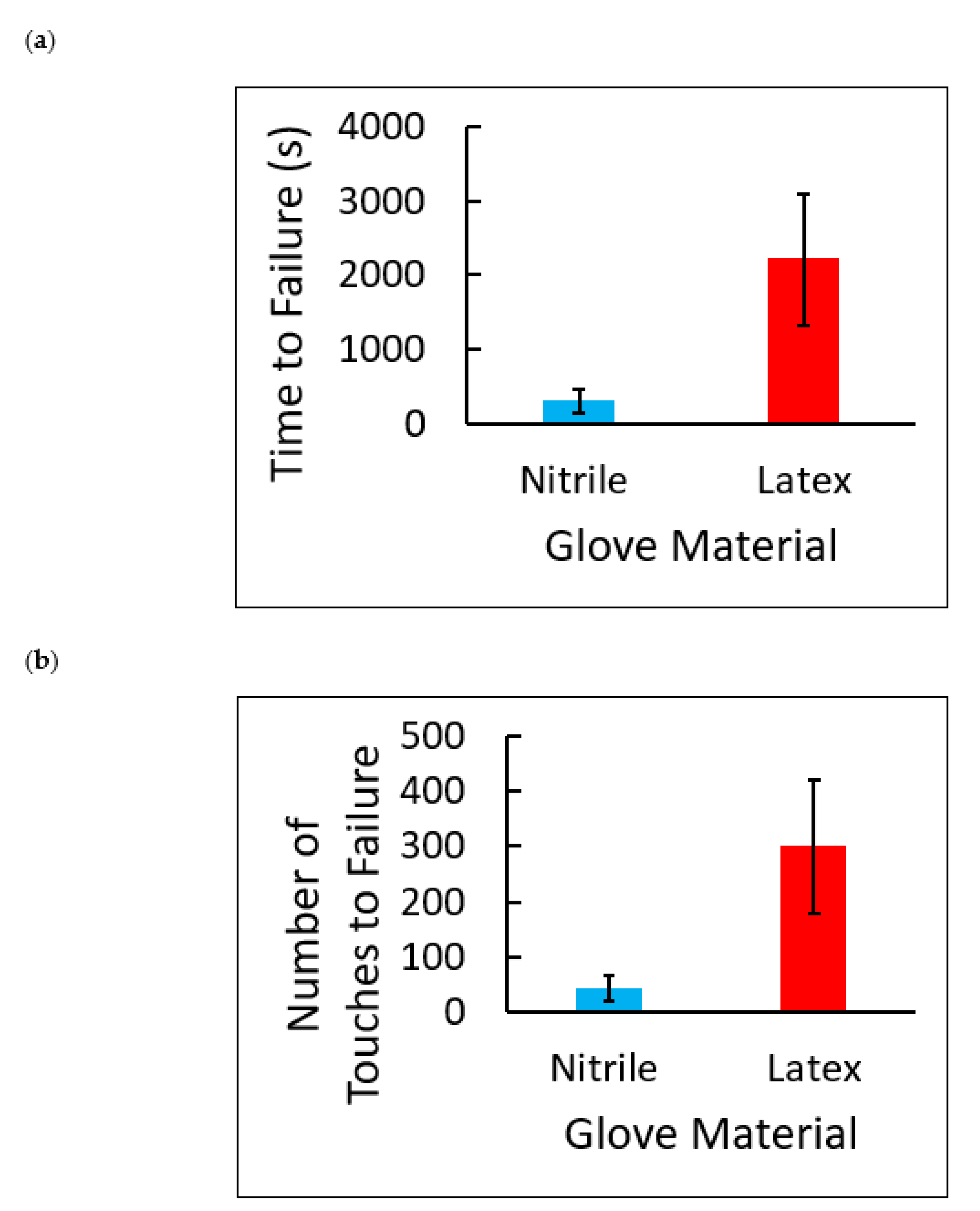
Inventions 07 00062 g013
Figure 14. (a) Failure times in seconds for nitrile and latex examination gloves. The average failure time for nitrile gloves was 300 ± 164 s, and the average failure time for latex gloves was 2206 ± 888 s. Each value is the mean of 5 ± SD. (b) Number of sandpaper touches to failure for nitrile and latex examination gloves. The average number of touches for nitrile glove failure was 42 ± 23 touches, and the average number of touches for latex gloves was 300 ± 121. Each value is the mean of 5 ± SD.
Inventions 07 00062 g014
Table 1. Description of each text field found on the homepage.
IDDescription
t0Describes what t4 contains and b1 and b5 manipulate
t1Describes what t5 contains and b2 and b6 manipulate
t2Describes what t6 contains and b3 and b7 manipulate
t3Describes what t7 contains and b4 and b8 manipulate
t4The number of touches the test will execute
t5The speed the of drum during the test
t6The force the drum will apply to the glove during the test
t7The number of touches between each spray, or “OFF” if the spray functionality is disabled
Table 2. Description of each button found on the homepage.
IDDescription
b0Begins a test with the settings as shown on the page
b1Decrements the number of touches to perform by 1 touch, up to a minimum of 1 touch
b2Decrements the speed of the drum by 0.1 mm/s, up to a minimum of 0.5 mm/s
b3Decrements the force of the drum on the glove by 100 mN, up to a minimum of 1000 mN
b4Decrements the number of touches between each spray by 1 or disables the touch functionality if the current value of t7 is “0”
b5Increments the number of touches to perform by 1 touch, up to a maximum of 65,535 touches
b6Increments the speed at which the drum will move by 0.1 mm/s, up to a maximum of 10.0 mm/s
b7Increments the force of the drum on the glove by 100 mN, up to a maximum of 20,000 mN
b8Increments the number of touches between each spray by 1, up to a maximum of 65,535, or enables the touch functionality if the current value of t7 is “OFF”
b9Opens the manual control page
Table 3. Description of the text field found on the glove depressurization page.
IDDescription
t0States that the glove depressurization has failed
Table 4. Description of the button found on the glove depressurization page.
IDDescription
b0Acknowledges the depressurization failure and returns to the home page
Table 5. Description of each text field found on the test page.
IDDescription
t0Title field
t1The current elapsed time of the test, not including depressurization time
t2The current touch the machine is executing and the total number of touches to execute
Table 6. Description of the button found on the test page.
IDDescription
b0Aborts the test and switches to the abort page
Table 7. Description of the button found on the test page.
IDDescription
t0States that the machine is currently aborting a test
Table 8. Description of each text field found on the glove failure page.
IDDescription
t0Title field
t1The elapsed time of the test up until glove failure, not including depressurization time
t2The current touch the machine was executing when the glove failed, and the total number of touches that were going to be executed
Table 9. Description of the button found on the glove failure page.
IDDescription
b0Returns to the home page
Table 10. Description of each text field found on the “test complete” page.
IDDescription
t0Title field
t1The elapsed time of the test up until the test was completed, not including depressurization time
t2The current touch number and the total number of touches that were going to be executed, which are the same at the end of a test
Table 11. Description of the button found on the “test complete” page.
IDDescription
b0Returns to the home page
Table 12. Touchscreen settings input for data collection. Note that these are the default settings.
Touch NumberSpeedForceSpray
503.5 mm/s15,000 mNOFF
Table 13. One-way analysis of variance of glove material versus break time in seconds.
Source of VariationDegrees of FreedomSum of SquaresMean SquaresF RatioProb > F
Between Groups19,076,5829,076,58217.79270.0029
Error84,081,040510,130
Total913,157,622
Table 14. One-way analysis of variance of glove material versus number of sandpaper touches to failure.
Source of VariationDegrees of FreedomSum of SquaresMean SquaresF RatioProb > F
Between Groups1166,152166,15217.42550.0031
Error876,2809535
Total9242,432
Publisher’s Note: MDPI stays neutral with regard to jurisdictional claims in published maps and institutional affiliations.

