Article

Novel Device Used to Monitor Hand Tremors during Nocturnal Hypoglycemic Events

by
Abdullah F. Al-Aboosi
1,2,* and
Rainer Fink
1
1
Department of Engineering Technology and Industrial Distribution, Texas A & M University, College Station, TX 77843-3122, USA
2
Department of Multidisciplinary Engineering, Texas A&M University, College Station, TX 77843-3122, USA
*
Author to whom correspondence should be addressed.
Inventions 2022, 7(2), 32; https://doi.org/10.3390/inventions7020032
Submission received: 22 February 2022 / Revised: 15 March 2022 / Accepted: 22 March 2022 / Published: 24 March 2022
(This article belongs to the Section Inventions and Innovation in Advanced Manufacturing)

Abstract

:
Diabetes is one of the lifelong diseases that require systematic medical care to avoid life-menacing ramifications. Uncontrolled diabetes can cause severe damage to most internal body organs, probably leading to death. Particularly, nocturnal hypoglycemic that occur usually at night during sleep. Severe cases of these events can lead to seizures, fainting, loss of consciousness, and death. The current medical devices lack to give the warning to reduce the risk of acquiring nocturnal hypoglycemic events because they use only for glucose monitoring during waking times. Consequently, the main goal of this work is to design and implement a new wearable device to detect and monitor tremors, which occur when a user has hypoglycemia (low blood sugar). The device can detect a frequency range of 4–12 Hz by using the accelerometer of Arduino Nano 33 BLE. It can send a signal to the phone application (app) via Bluetooth Low Energy (BLE). Once the phone receives a signal, the phone application can activate an alarm system to wake up the patient, call three selected contacts number, and universal emergency number. In case of the user is unresponsive, the app can provide the patient’s location, name, and date of birth to the emergency contacts numbers and universal emergency number. Additionally, the device cost is economically feasible and competitive compared to other medical devices.

1. Introduction

Diabetes can cause serious consequences for health and wellbeing if it is not properly monitored and controlled. According to the Centers for Disease Control and Prevention (CDC), 30.3 million Americans which is 9.4 percent of the U.S. population have diabetes. Another 84.1 million have prediabetes, a condition that if not treated often leads to type 2 diabetes within five years [1]. The percentage of diabetics has increased in correlation to the population [2,3]. The hypoglycemia that occurs nocturnally has increased the risk of death. The studies of [4,5] state that when blood glucose levels drop below 70 mg/dL while a person sleeping at night, the nocturnal hypoglycemia event will occur. Most research speculations report that hypoglycemic events mainly occur at night when the patient is unlikely to wake up and realize symptoms before becoming worse [6]. Accordingly, severe hypoglycemia can cause death among young people with type one diabetes. Tremor is one of the widespread symptoms that typically begin to occur when the blood sugar level goes below the normal level of 70 mg/dL [7,8]. According to [9], the hand tremor frequency is estimated between the value of 4 to 9 Hz, while [10] shows that the actual tremor can be detected between 4 to 12 Hz. The accelerometer was introduced to detect the tremor when it occurs [11]. In the study [12], a wearable device was used to measure the tremor by using electromyography. The inertial sensors were used properly to evaluate the diagnoses and treatment of tremors that are caused by several diseases such as Parkinson’s disease [13,14]. Using a smartphone is another device that can be used effectively to detect and monitor pathological tremors [15]. To improve data transmission and lessen the power usage in tremor devices, a data compression method was used and implemented. [16]. Nowadays, smartphones have increased the accuracy of monitoring system due to its low cost and ability to connect wirelessed [17]. Based on a prior study [18], a cell phone accelerometer was used to accurately detect termites. Thus, it was offered to use as a monitoring device. The accelerometer is an essential device to measure acceleration for most physical activities [19,20,21,22,23]. The author of the study [24] argues that accelerometer sensor is a good method to measure the position and the acceleration. The raw data that the accelerometer produce is always in time domain [25]. For that reason, the Fast Fourier transform (FFT) can be applied to convert the signal from original domain time to frequency domain [26]. Currently, there is no existing technology or commercial product that can alert users when they are experiencing a nocturnal hypoglycemic event. The main goal of this work is to provide a solution by detecting the tremors in the hand and alerting users that their blood sugar is critically low. Consequently, the wearable device Diabetes Attacks (DiAtack) is designed to alarm users, universal emergency number, and contact three emergency numbers once a nocturnal hypoglycemic event starts

2. Materials and Methods

2.1. General Description

The key purpose of designing and implementing the DiAtack is to detect tremors caused by low blood sugar levels through combining a noninvasive wearable device, an application, and a central alarm unit. Therefore, the proposed device can be used to precisely monitor the user’s condition by detecting hand tremors when Hypoglycemia occurs. Once tremors are detected by the wearable band, the phone app will send a signal to activate the alarm system. If the alarm fails to wake up the patient, three emergency contacts will be notified by the phone app, in addition to contacting universal emergency number. The android mobile application is used to communicate with the wearable device to save the data and activate the emergency protocols which are based on a specific frequency range. There are two operating scenarios for the mobile application. The first scenario is sending a signal to the Arduino Nano BLE, which is was manufactured by (Arduino, Scarmagno, Italy), to activate the alarm system. While the second scenario is notifying three emergency contacts along with universal emergency number of a users’ condition and their location. Furthermore, the mobile application developed by MIT App Inventor (Massachusetts Institute of Technology, Cambridge, MA, USA) can be used to save raw data for research purposes. The proposed system is designed to wake up a patient by using a bright light and loud sound. The app also allows a patient to save a recorded message that can be sent to three phone numbers and universal emergency number to inform them about the patient’s information when the alarm system fails to wake up a patient.

2.2. Conceptual Block Diagram

A conceptual block diagram of the proposed system shows the high-level superstructure and highlights subsystems such as a wearable device (DiAtack), smartphones, and a central unit, as shown in Figure 1. The wearable device is designed to be capable to detect the tremor of nocturnal hypoglycemic in the range of 4–12 Hz. Bluetooth is used to communicate the phone app with DiAtack. Thus, the phone app will be able to activate an alarm system and send three texts to the emergency contact once it detects an input of 4–12 Hz.

2.3. Functional Block Diagram

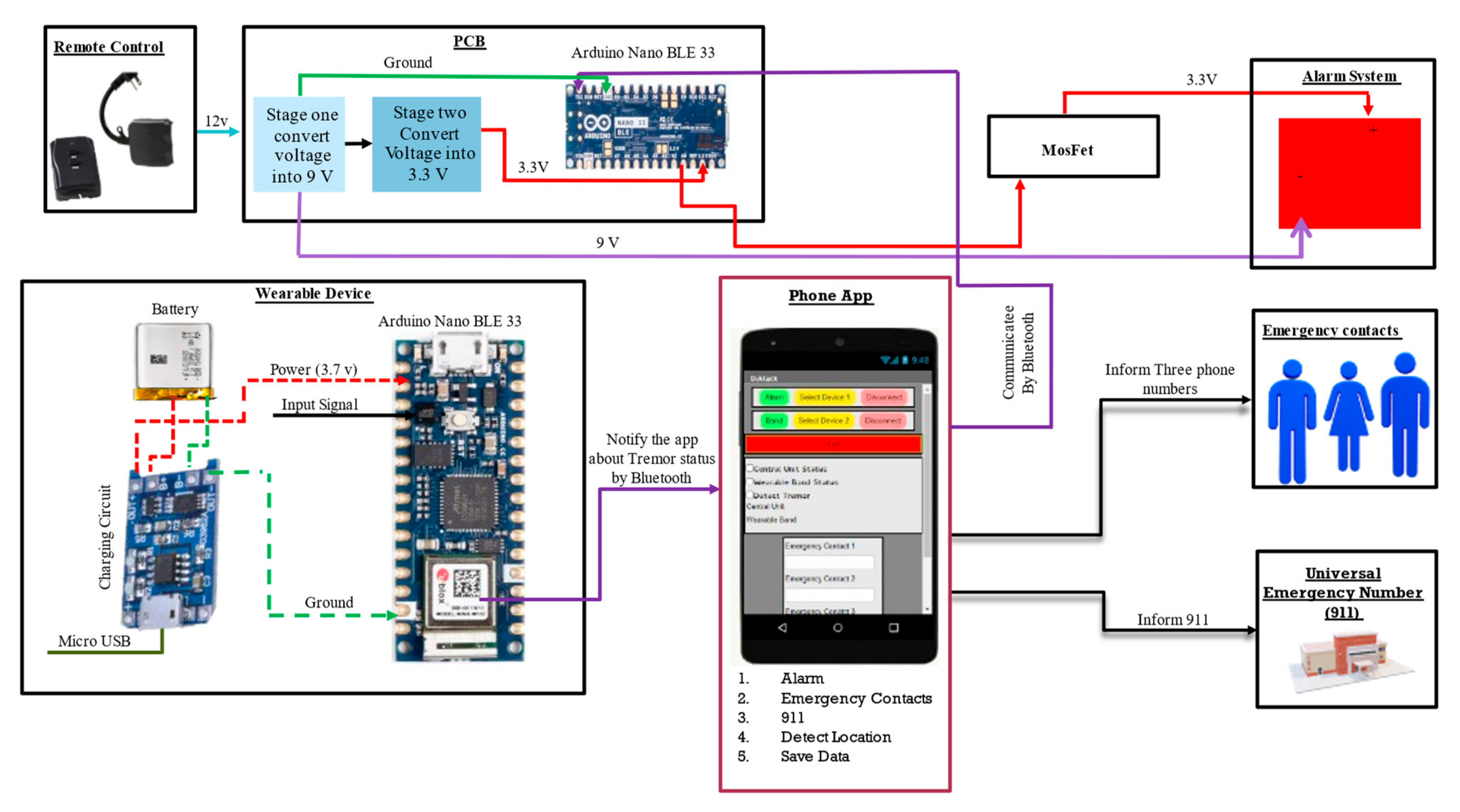
In the DiAtack system, a wearable device is communicated with a phone application to detect tremors. The tremor that occurs during hypoglycemia events can be detected by using an accelerometer. Additionally, the phone app will be communicated with PCB through an Arduino Nano BLE to turn on the alarm system. The PCB consists of several stages that reduce a voltage to power the alarm system as well as the microcontroller. To improve the reliability of the proposed device, two options have been added in case the alarm system could not wake up the diabetic patient by contacting emergency contact and universal emergency number. Figure 2 shows the functional block diagram of DiAtack.

2.4. Printed Circuit Board (PCB)

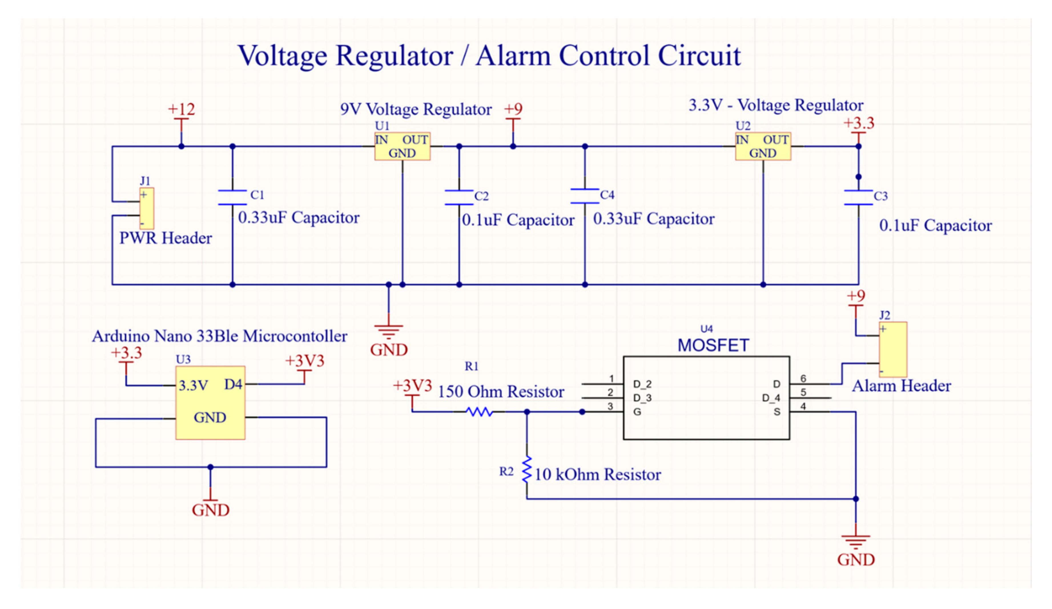
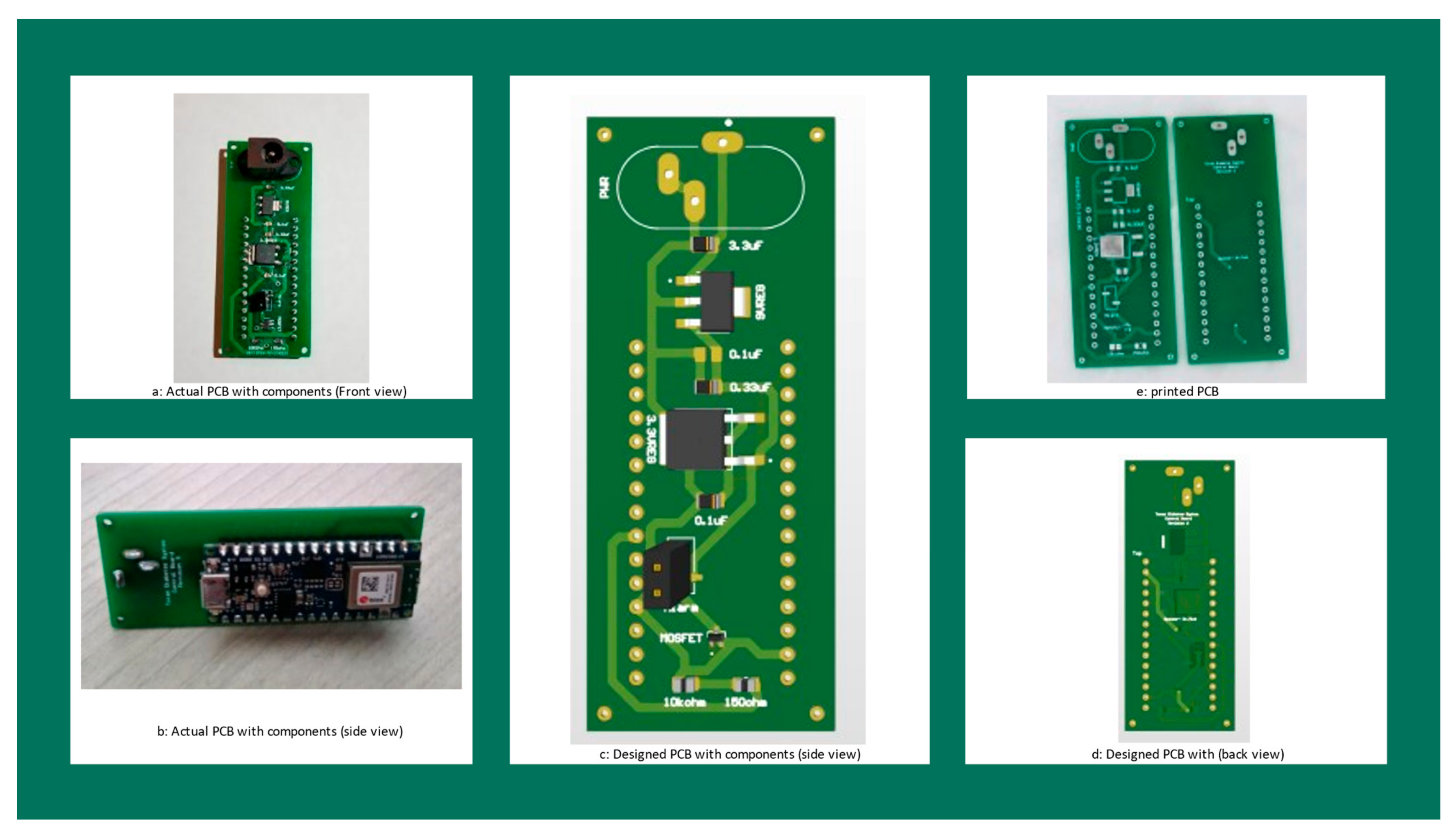
The PCB was designed by using Altium Software by (Altium Software company, San Diego, CA, USA). The hardware aspect of the device is to design a PCB that can host the voltage regulation circuit. The Arduino Nano 33 BLE is used to accommodate a Bluetooth module. The Bluetooth module receives a signal from the phone application and activates the processor. The microcontroller is used to activate the alarm to which it is connected too. The microcontroller needs 3.3 V for its operating voltage and the alarm needs 9 V. The whole device can be connected to the wall through a 12 V wall converter. A voltage converter circuit is used to attain the required operating voltages. To achieve the 9 V target for the alarm, an L78S09CV voltage regulator is used. The load dropout voltage for the device is 1.5 V which is less than 3 V. It is the difference of 12 V to 9 V conversion. For optimal performance, the voltage regulator will have a 0.33 uF capacitor connected to the input, and a 0.1 uF capacitor connected to the output. To achieve the 3.3 V for the microcontroller, a uA78M33C voltage regulator is needed. The load dropout voltage for the device is 2 V, which is less than 6 V that is a result of the 9 V to 3 V conversion. For optimal performance, the voltage regulator has a 0.33 uF capacitor that is connected to the input, and a 0.1 uF capacitor that is connected to the output. To activate the alarm, the microcontroller requires to be connected to a MOSFET, which will act as a switch. The microcontroller can send 3 V to the MOSFET which activates the alarm. The alarm also has an 82 Ohm resistor between itself and the 9 V power supply which can limit the current going to the alarm with 109 mA. Figure 3 shows the alarm control circuit.

2.5. Software Flowchart/Algorithm

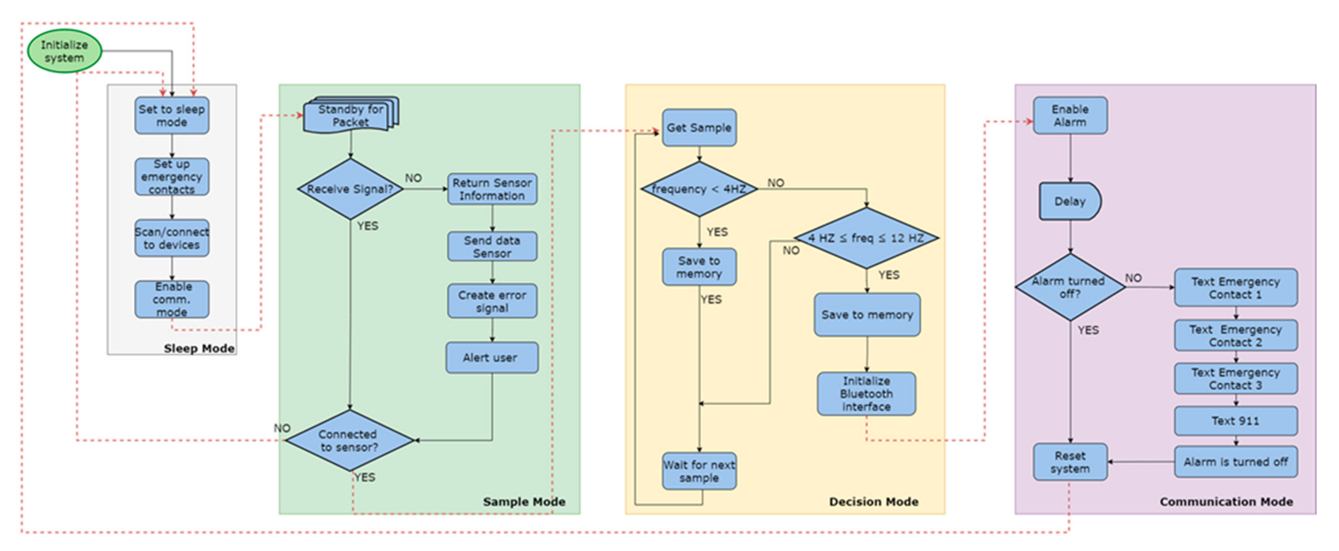
The DiAtack Application was developed using MIT App Inventor, which is a web application integrated development that allows app developers to create their first application. In the sleep mode phase, the mobile application is initialized by the user and set to sleep mode until the user sets up the emergency contacts. To make this happen, creating a list with all the saved numbers requires. Each saved number is set to receive a predetermined message that states: This is an automated message from the DiAtack system to inform the protocol that the patient’s blood sugar is low, and a patient is in a critical situation. Next, to scan and connect to multiple peripherals, BLE is designed to consume less power while maintaining comparable functionality. Additionally, the BLE protocol allows a device to attain either a central or peripheral role. Since MIT app inventor requires a separate Bluetooth LE component for each device. In this case, the service Universally Unique Identifier (UUID) and a characteristic UUID were needed for the wearable device and the central unit. A characteristic and services are all assigned and referenced using Universally Unique Identifier (UUID). These values were determined based on the Arduino values that were assigned in the peripheral’s configuration. Each UUID Service and UUID Characteristic needs to be initialized along with assigning two buttons that oversee scanning for each component. If there is a successful connection, a checkmark confirms this step. To initiate the communication mode, the user presses the save contact button. Once the save contact button is pressed, the phone application will begin receiving data from the wearable device using a synchronized clock that transmits the strings in real-time. If a packet is received, the application checks again to make sure the sensor is connected to ensure there are no packets lost. Once there is a successful connection, a checkmark confirms this step. The decision mode begins immediately when both checkmarks are shown and the MAC address for each device matches each peripheral. Figure 4 shows the received signal will determine the decision, if not, the sensor information will be returned, send sensor data, create an error signal alert user and it will go to the next decision whether connected to the sensor or not. However, if the signal is received, then the program will go to whether connected to the sensor or not. During the decision phase, each item in this list is put through a for loop with an if condition. If the condition is set to read each received item and check whether the values fall between 4 and 12 or if the value falls under 4. This takes into account the deliverable of enabling the system once the frequency of the user’s tremor falls between this range. For both conditions, the string is first received, and the string is read through the appropriate service and characteristic UUID. In the back end of the app, the app is continuously saving the raw data of the XYZ values into individual text files. After a tremor is detected, the mobile application initializes the connection between the application and the central unit. Figure 4 shows the decision mode. The communication mode is responsible for enabling the alarm. Once the App active the alarm, at the same time it will activate the emergency protocol. This protocol will send three text messages to the emergency contacts and universal emergency number. Figure 4 summarizes DiAtack Mobile Application.
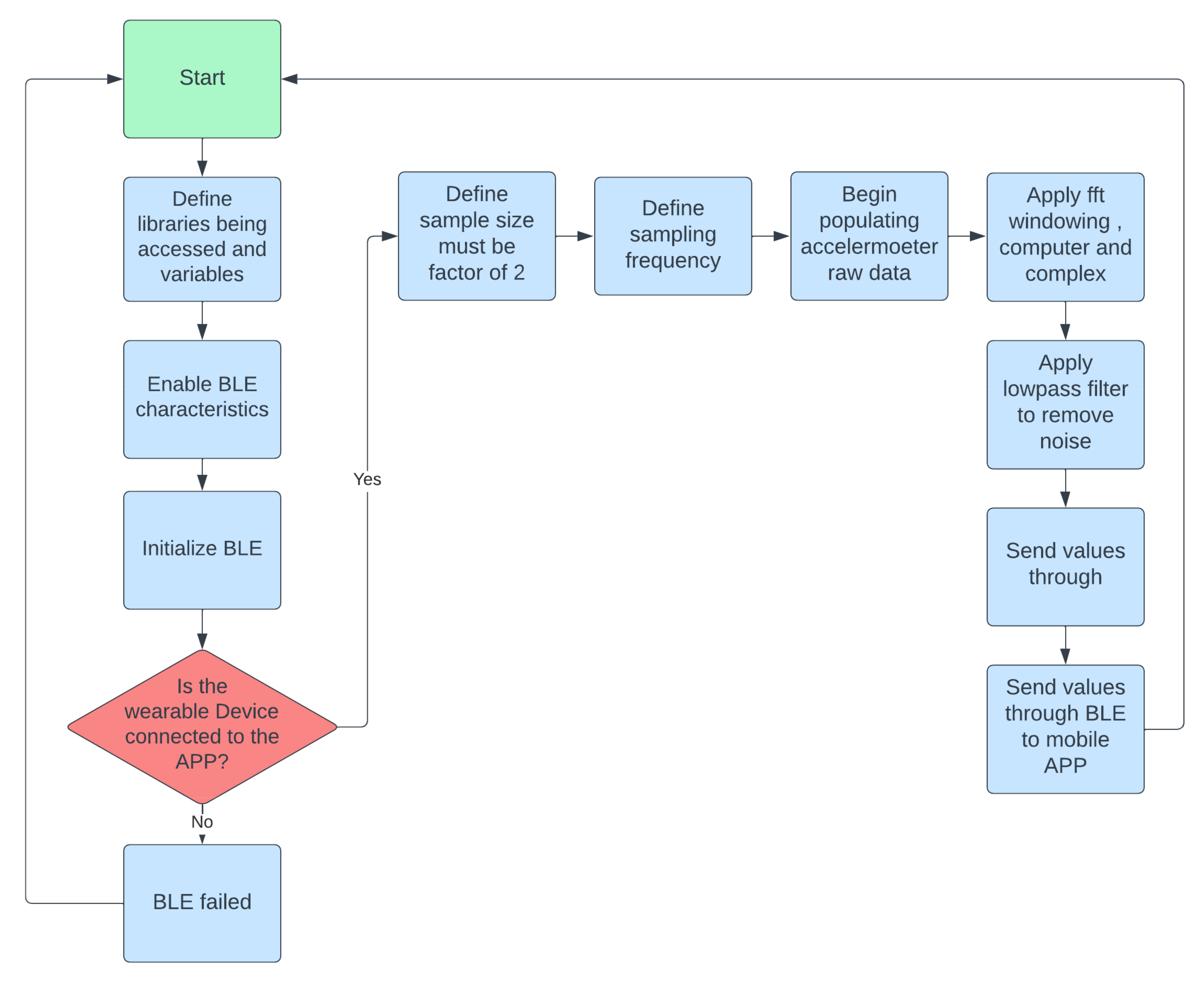
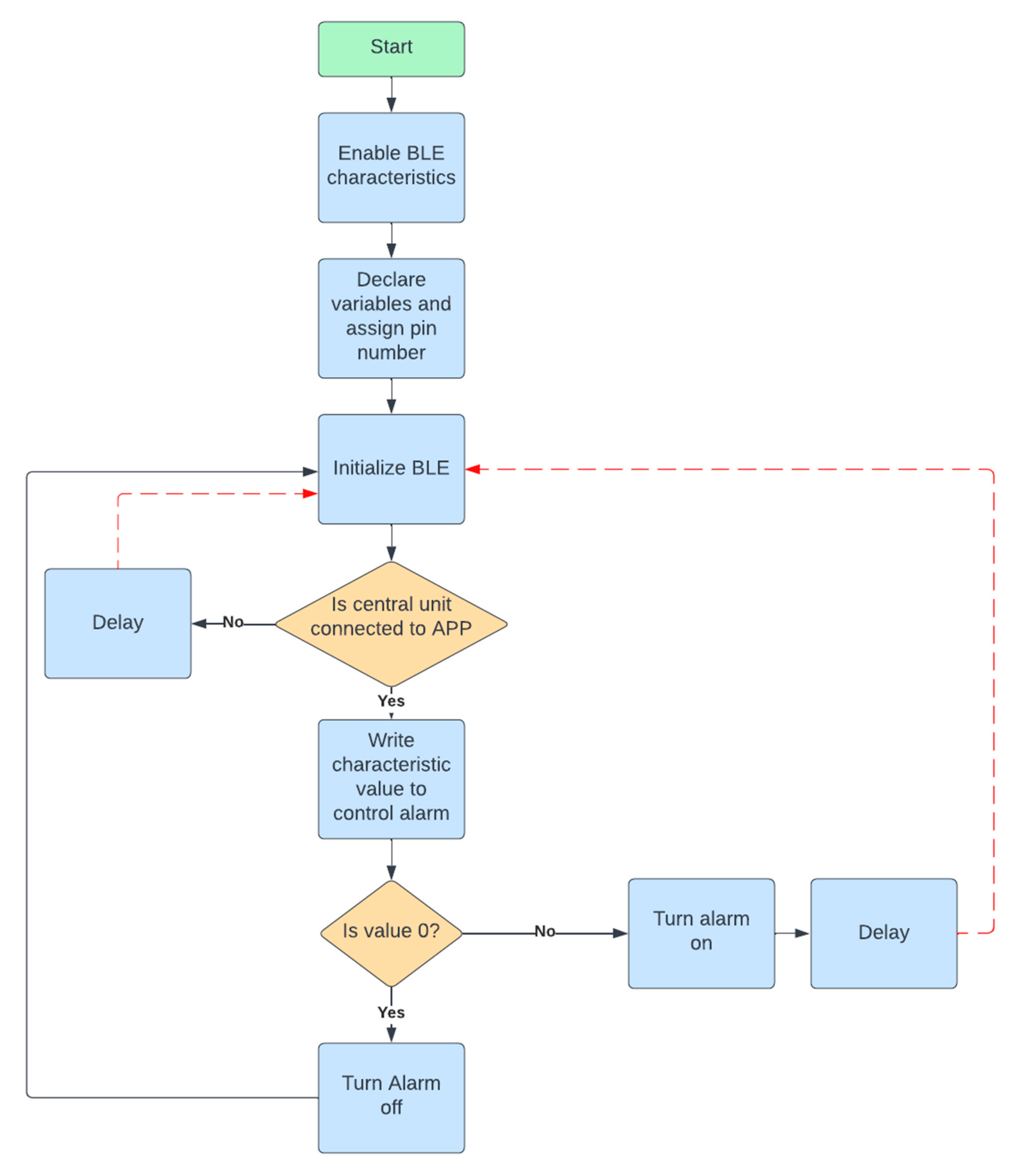
The first step of the wearable band was to define the libraries, activate the BLE, and initialize the BLE. The sample size was defined along with the sampling frequency. In addition, the code can start acquiring the accelerometer raw data, and apply Fast Fourier Transformer (FFT). Finally, the low passband filter was applied to remove the noise as shown in Figure 5. Central Unit was required to enable the BLE. The condition was set whether the phone app is connected to the central unit. When the condition is met, the characteristic value would been written to the alarm. Additionally, if the value is equal to zero, the alarm will be off. While if the value is one, the alarm will be active as shown in Figure 6.

2.6. Frequency-Time Domain Transformation

An accelerometer generates XYZ coordinate points that represent the direction and position of the acceleration happened. The X coordinate represents the acceleration that occurs in both the left and right directions. While the Y coordinate shows the acceleration in the forward and backward paths. Additionally, the Z coordinate describes the acceleration direction whether is up or down. Figure 7 shows the accelerometer direction.
In this study, the obtained data of the accelerometer refers to the rate of change in the velocity of an object per unit of time. The measured data will be in meter per second squared (m/s2) or in G-forces (g). Since data is in the time domain, the FFT was used to transform time-domain data to the frequency domain. The typical Fourier transformation equation is shown below [27]:
X j w   = u t .   e j w t
While the inverse Fourier Transformation, which is used to transform signal in the frequency domain ω to one in the time domain, is given in Equation (2) [28]:
x t   = 1 2 π X j w .   e j w t d w
The X(jw) and x(t) data of the digital system have a finite number of N samples that result in discrete Fourier Transformation, as given below [29]:
D s = k = 0 N 1 u k   exp ( j . n ( 2 π k N ) )
The inverse of discrete Fourier Transformation is given in Equation (4) [29]:
u k = 1 N n = 0 N u n   exp ( j . k ( 2 π . n N ) )
During this process, the frequency and absolute time values are discrete Fourier Transformation [30]. These two variables will be based on the number of samples and sample frequency,
Δ f = 1 N Δ t = f T N
When the discrete Fourier Transformation is applied, the number of sample time can be converted to the number of sample frequency [31]. Indeed, the time data are real number and the complex frequency samples are conjugate complex uniform as shown below:
U N n = U n
The above-mentioned equations were used to process the signal of the accelerator to obtain the data in frequency domain. Data filtration was used to filter the data between the desired frequency between 4–12 Hz.

3. Results and Discussion

The Tinkecard-3D Modeling Software that created by Tinkecard (San Francisco, CA, USA) was used to build the wearable band to hold all the components inside it. The wearable case has a sliding door on top. The sliding door has a hole to allow users to charge their wearable band using s micro-USB cable. The charging LED indicator turns red when charging and becomes green when the device is fully charged. Figure 8 shows the printed wearable case, its components, and the front view of it in a user’s hand.
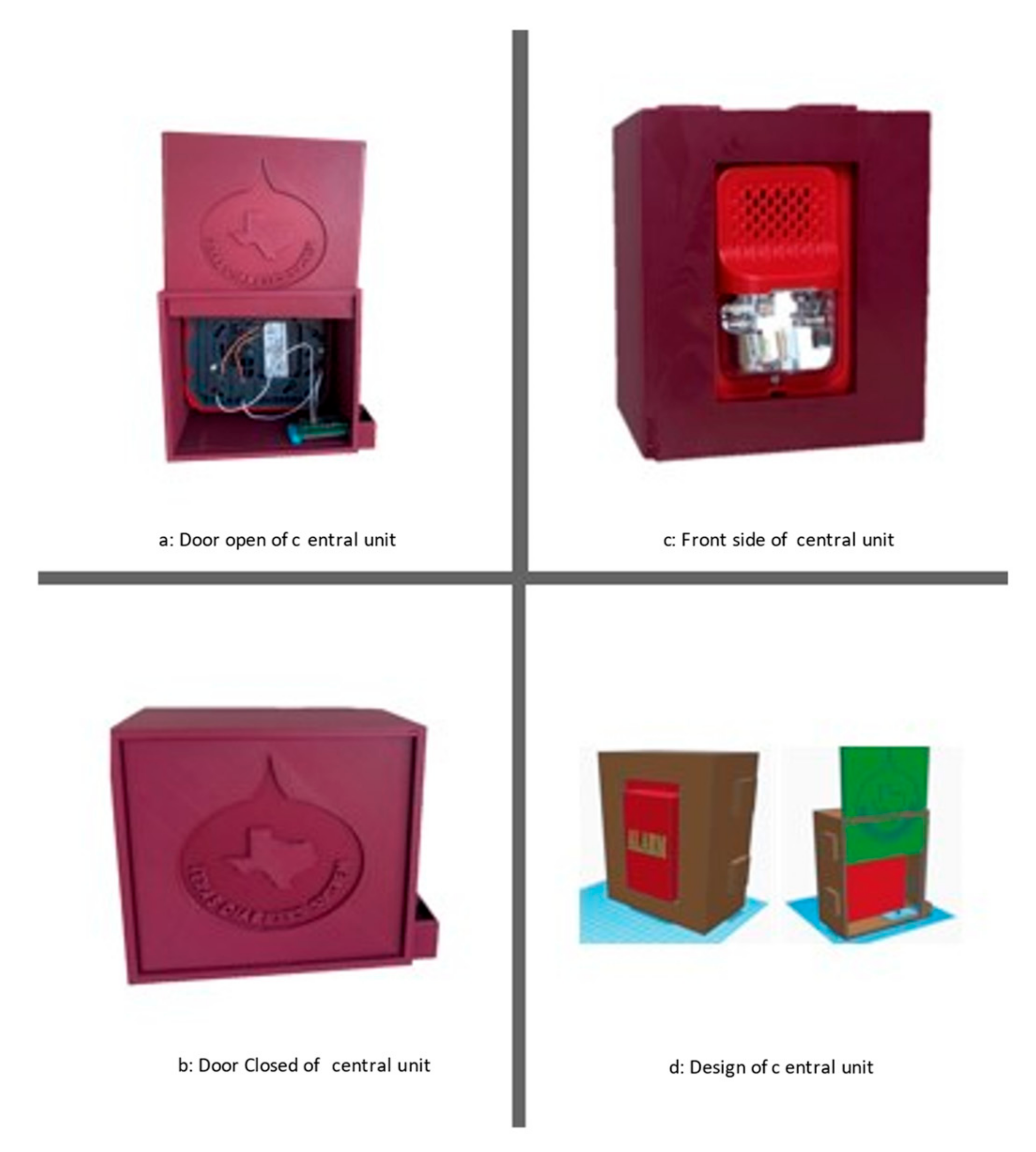
Figure 8 shows the printed wearable case, its components, and the front view of it in a user’s hand. The wearable band was included a charging circuit, Arduino Nano BLE 33, and a lithium-ion battery inside the case. The components fit inside the case and do not move when the patient event occurs. The wearable device fitted comfortably on the user’s hand and was not fallen off overnight. The Central Unit needs to hold the alarm and PCB. The PCB contains the Arduino Nano BLE 33. The Central Unit case has a slidable door on the back as shown in Figure 9. The front of the alarm is visible to make users aware of the flashing light and hear the audible sound. On the right side of the alarm, there is a hole in the case to allow the user to plug the adaptor into the PCB as shown in Figure 8.
The PCB was built by using the equipment of (Texas A&M University, College Station, TX, USA). The components are on the top side of the PCB while the Arduino Nano BLE 33 is on the bottom side of the PCB. The PCB powers the Arduino Nano BLE 33 and powers the alarm when 4 to 12 Hz is detected as shown in Figure 10.
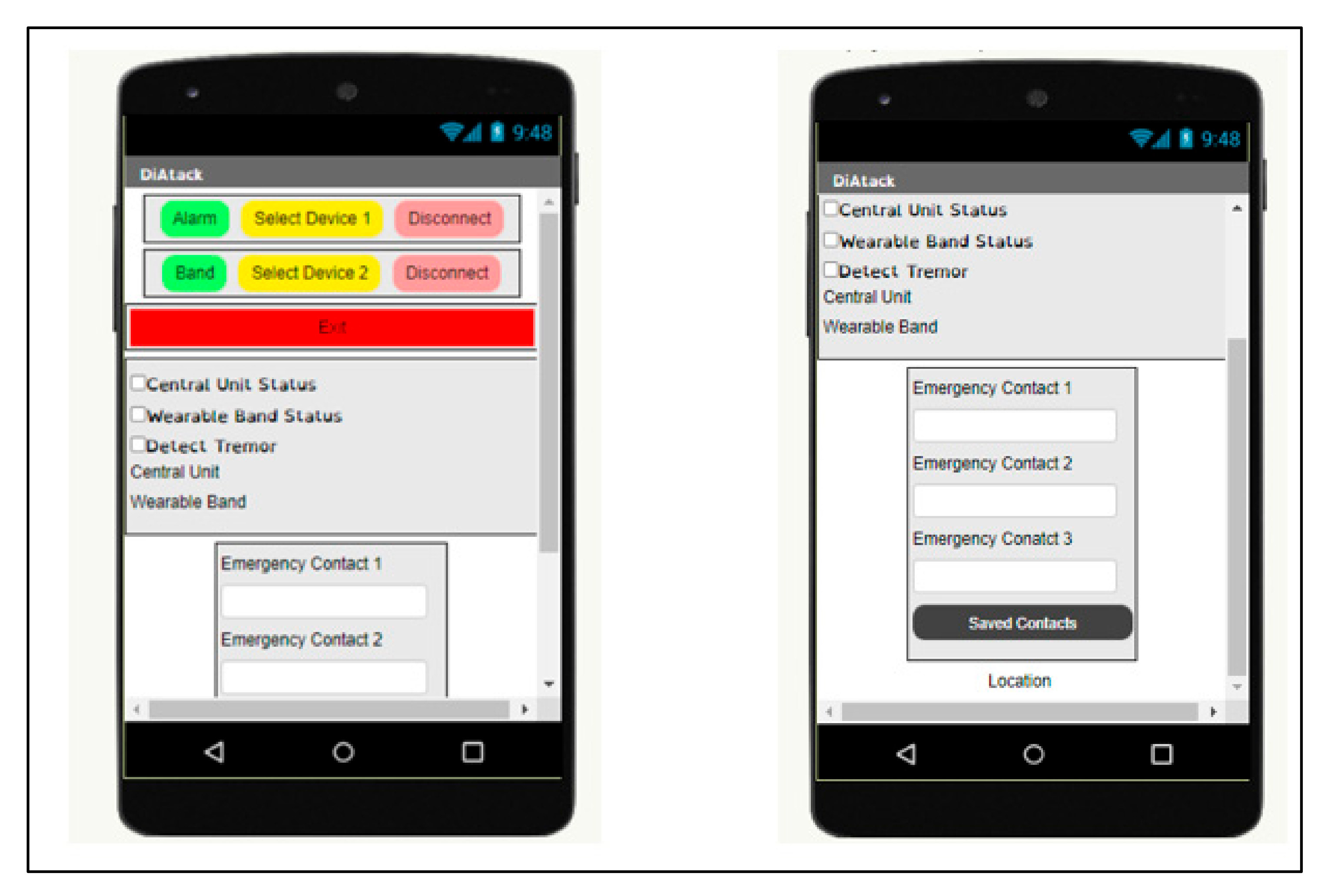
Three key buttons were incorporated into the mobile application. The green “Alarm” button scans for the alarm to be connected. The yellow button can be used to show all devices that might be found in the surrounded area. The red “Exit” button allows the user to exit the mobile application by disconnecting from the wearable device. Underneath the “Exit” button, there is an area that displayed whether the app is connected to the device. A green checkmark and text were shown up on the screen to indicate that the device was connected to the mobile application. Additionally, there are three text boxes that allowed the user to enter three emergency contacts. The “Saved Contacts” button needs to be pressed after entering the phone numbers. The user’s location was displayed at the bottom of the mobile application. Figure 11 shows the mobile application.
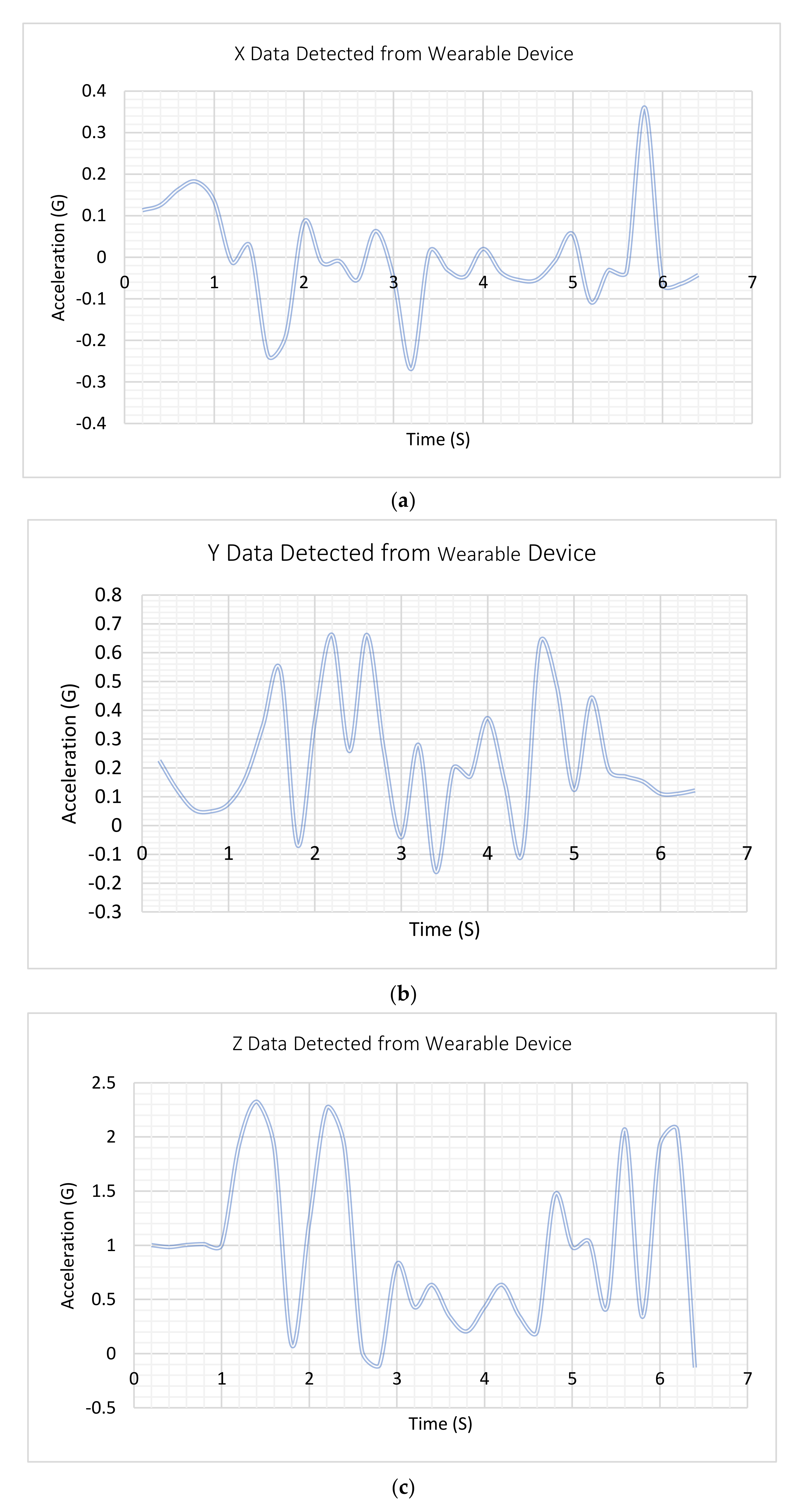
The Test Plan was implemented to test each component of the proposed system and its software. The accelerometer, Arduino Nano 33 BLE, and alarm were tested individually. While the PCB circuit design was tested by using Multisim simulation and built on the breadboard prior to starting the fabrication work. The wearable band was tested to verify its performance through capturing the accelerometer data as shown in Figure 12.
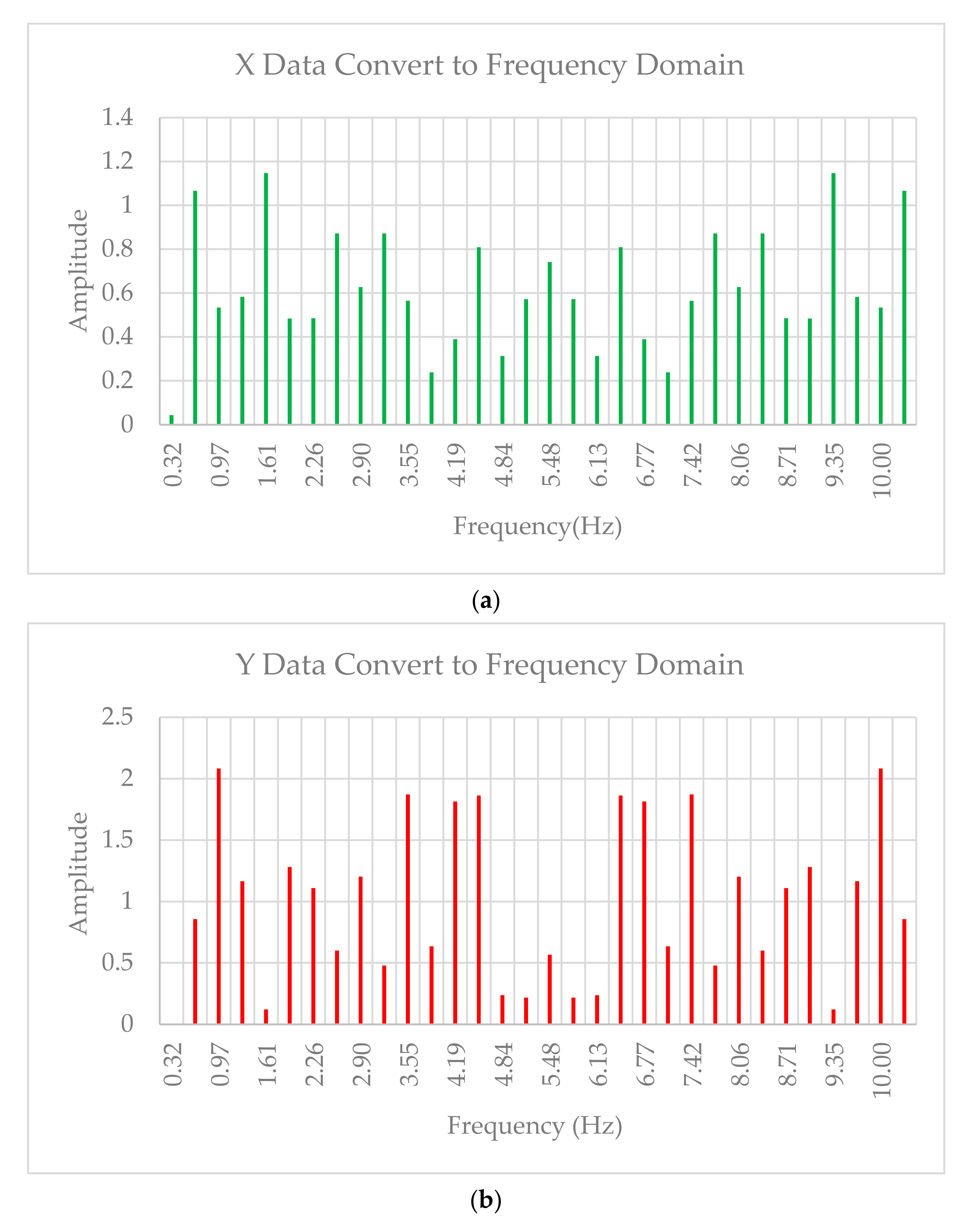
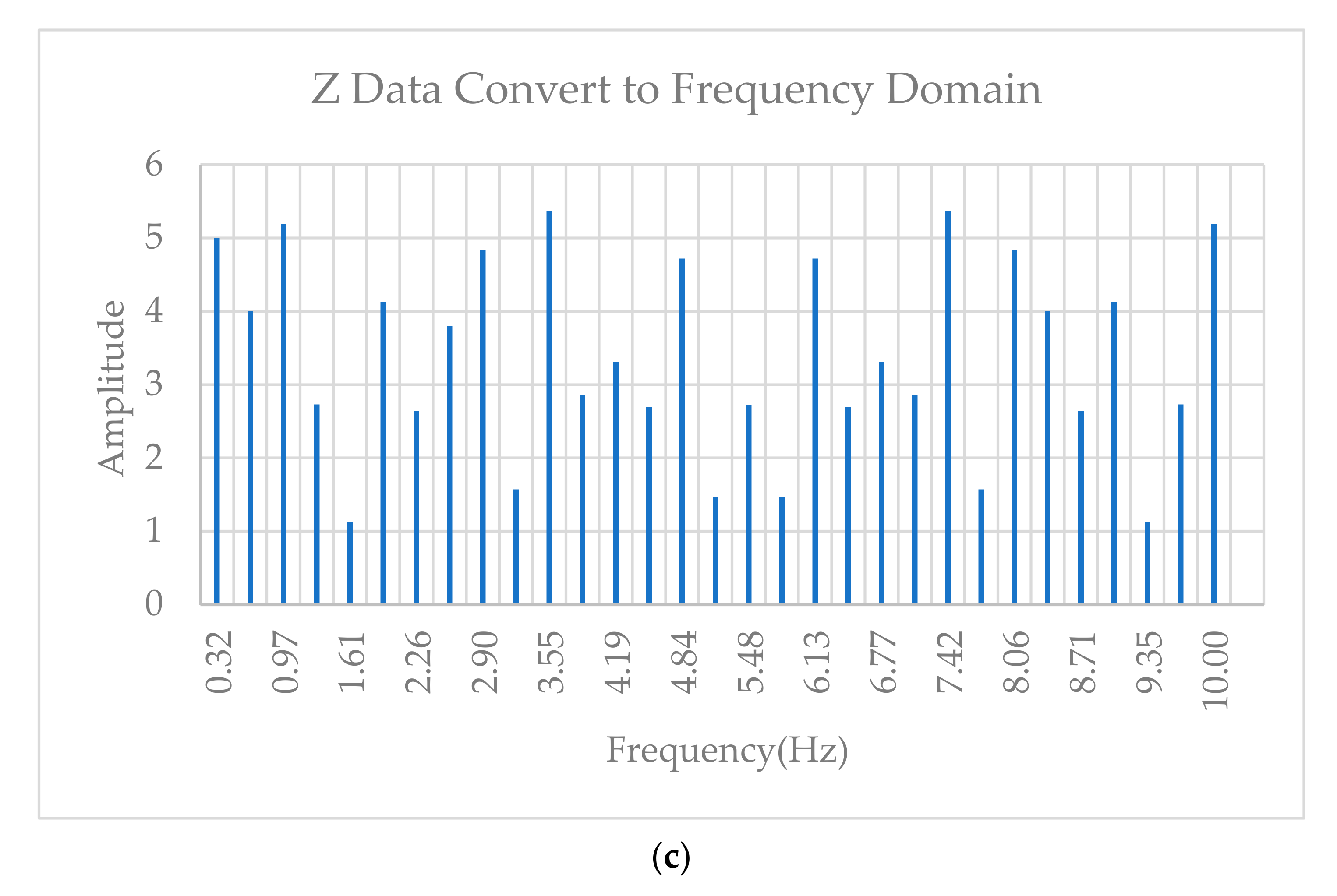
Figure 12 shows the data that was obtained by the wearable band. These data were in the time domain. Therefore, the equations of Section 2.6 were used to convert the obtained data into the frequency domain as shown in Figure 13.
A low pass filter was used to detect and select the desired 4–12 Hz range of frequencies while preventing signals at unwanted frequencies from passing through the system. The data was captured on both sides of sending and receiving to check the accuracy of the system as shown in Figure 14 and Figure 15.
The final integrated system was tested and validated to verify that the device meets all design specifications and functional requirements. During the testing and validation process of the system, the wearable band was sent 21 data values. The data was captured efficiently by the mobile application without losing any value. Digital multimeters, function generators, frequency counter, and other electronics tools were used to check the integrated system as in Table 1.
The visual test was used to examine each component. This test ensures that each component is operating and meets product expectations. The test was carried out on all hardware components that include the Accelerometer, Arduino Nano 33, alarm, PCB circuit, Alpha PCB, and Alpha Android app.

4. Conclusions

The novel contribution of this work is to design, implement, operate, and test a medical device that has capability to early detect nocturnal hypoglycemic that occur usually at night during sleep. Consequently, the prior detection will avoid a patient serious event such as seizures, fainting, loss of consciousness, and death. The system of the proposed device consists of a wearable device (DiAtack), a smartphone, and a central unit. The new wearable device (DiAtack) has been designed to detect and monitor tremors, which occur when a user has hypoglycemia (low blood sugar). The entire system has been tested. The major test process steps were included visual test, input, and output voltage, output current, MOSFET, functionality, BLE connection, notification, and data storage. The device showed up the ability to detect a frequency range of 4–12 Hz by using the accelerometer of Arduino Nano 33 BLE. It could send a signal to the phone application (app) via Bluetooth Low Energy (BLE). Once the phone has received a signal, the phone application has activated an alarm system to wake up the patient, call three selected contacts number, and universal emergency number. Additional test has been performed in case of a user was not response for alarm, the app offered an immediate provision for the patient’s location, name, and date of birth to the emergency contacts numbers and universal emergency number. Furthermore, the system is economically feasible and competitive compared to other medical devices. The limitation of this study is to reduce the size of the wearable device that makes it more comfortable to the users. Therefore, the proposed system of this study is a very promising medical device that probably needs further development to be better adapted to the patient’s needs. Adopting iPhone Operating System (iOS) can be added new feature to the system to allow users using various mobile applications.

Author Contributions

This paper is collaborative research between A.F.A.-A. and R.F. Conceptualization, methodology, software, validation, formal analysis investigation, resources and data curation was handled by A.F.A.-A. The writing—original draft preparation, writing—review by A.F.A.-A. In addition, editing and supervision was carried out by R.F. All authors have read and agreed to the published version of the manuscript.

Funding

This research received no external funding.

Institutional Review Board Statement

Not applicable.

Informed Consent Statement

Not applicable.

Conflicts of Interest

The authors declare no conflict of interest.

Nomenclature

X Fourier transformation
x Inverse Fourier Transformation
D s Discrete Fourier Transformation
u k Inverse discrete Fourier Transformation
NNumber of samples
j Imaginary numbers
fTSample frequency
Δ t Distance between time samples
Δ f Distance between frequency samples.

References

  1. CDC. New CDC Report: More than 100 Million Americans Have Diabetes or Prediabetes; Centers for Disease Control and Prevention: Atlanta, GA, USA, 2018. [Google Scholar]
  2. Abdelhamid, Y.A.; Bernjak, A.; Phillips, L.K.; Summers, M.J.; Weinel, L.M.; Lange, K.; Chow, E.; Kar, P.; Horowitz, M.; Heller, S.; et al. Nocturnal Hypoglycemia in Patients With Diabetes Discharged From ICUs: A Prospective Two-Center Cohort Study. Crit. Care Med. 2021, 49, 636–649. [Google Scholar] [CrossRef]
  3. Jones, A.G.; McDonald, T.J.; Shields, B.M.; Hagopian, W.; Hattersley, A.T. Latent Autoimmune Diabetes of Adults (LADA) Is Likely to Represent a Mixed Population of Autoimmune (Type 1) and Nonautoimmune (Type 2) Diabetes. Diabetes Care 2021, 44, 1243–1251. [Google Scholar] [CrossRef] [PubMed]
  4. Saito, K.; Okada, Y.; Torimoto, K.; Takamatsu, Y.; Tanaka, Y. Blood glucose dynamics during sleep in patients with obstructive sleep apnea and normal glucose tolerance: Effects of CPAP therapy. Sleep Breath. 2021, 1–11. [Google Scholar] [CrossRef]
  5. Boscari, F.; Ferretto, S.; Cavallin, F.; Bruttomesso, D. Switching from predictive low glucose suspend to advanced hybrid closed loop control: Effects on glucose control and patient reported outcomes. Diabetes Res. Clin. Pract. 2022, 185, 109784. [Google Scholar] [CrossRef]
  6. Yorgason, J.B.; Saylor, J.; Ness, M.; Millett, M.; Floreen, A. Emerging Ideas. Health Technology Use and Perceptions of Romantic Relationships by Emerging Adults With Type 1 Diabetes. Fam. Relat. 2021, 70, 1427–1434. [Google Scholar] [CrossRef]
  7. Reno, C.M. Severe hypoglycemia-induced sudden death is mediated by both cardiac arrhythmias and seizures. Am. J. Physiol. Endocrinol. Metab. 2018, 315, E240–E249. [Google Scholar]
  8. Picerno, P.; Iosa, M.; D’Souza, C.; Benedetti, M.G.; Paolucci, S.; Morone, G. Wearable inertial sensors for human movement analysis: A five-year update. Expert Rev. Med. Devices 2021, 18, 79–94. [Google Scholar] [CrossRef]
  9. Stiles, R.N. Frequency and displacement amplitude relations for normal hand tremor. J. Appl. Physiol. 1976, 40, 44–54. [Google Scholar] [CrossRef]
  10. Elble, R.J.; Ondo, W. Tremor rating scales and laboratory tools for assessing tremor. J. Neurol. Sci. 2022, 435, 120202. [Google Scholar] [CrossRef]
  11. Ang, W.T.; Khosla, P.K.; Riviere, C.N. Design of all-accelerometer inertial measurement unit for tremor sensing in hand-held microsurgical instrument. In Proceedings of the 2003 IEEE International Conference on Robotics and Automation (Cat. No.03CH37422), Taipei, China, 14–19 September 2003; Volume 2, pp. 1781–1786. [Google Scholar] [CrossRef] [Green Version]
  12. Vescio, B.; Quattrone, A.; Nisticò, R.; Crasà, M.; Quattrone, A. Wearable Devices for Assessment of Tremor. Front. Neurol. 2021, 12, 680011. [Google Scholar] [CrossRef]
  13. Iosa, M.; Picerno, P.; Paolucci, S.; Morone, G. Wearable inertial sensors for human movement analysis. Expert Rev. Med. Devices 2016, 13, 641–659. [Google Scholar] [PubMed]
  14. Monje, M.H.G.; Foffani, G.; Obeso, J.; Sánchez-Ferro, Á. New sensor and wearable technologies to aid in the diagnosis and treatment monitoring of Parkinson’s disease. Annu. Rev. Biomed. Eng. 2019, 21, 111–143. [Google Scholar] [PubMed]
  15. Daneault, J.-F.; Carignan, B.; Codère, C.; Sadikot, A.F.; Duval, C. Using a Smart Phone as a Standalone Platform for Detection and Monitoring of Pathological Tremors. Front. Hum. Neurosci. 2013, 6, 357. [Google Scholar] [CrossRef] [PubMed] [Green Version]
  16. Premkumar, M.; Ashokkumar, S.; Jeevanantham, V.; Pallavi, S.A.; Mohanbabu, G.; Raaj, R.S. Design of cost-effective real time tremor alerting system for patients of neurodegenerative diseases. Mater. Today Proc. 2021. [Google Scholar] [CrossRef]
  17. Aviles-Cruz, C.; Rodriguez-Martinez, E.; Cortez, J.V.; Ferreyra-Ramirez, A. Granger-causality: An efficient single user movement recognition using a smartphone accelerometer sensor. Pattern Recognit. Lett. 2019, 125, 576–583. [Google Scholar] [CrossRef]
  18. Fraiwan, L.; Khnouf, R.; Mashagbeh, A.R. Parkinson’s disease hand tremor detection system for mobile application. J. Med. Eng. Technol. 2016, 40, 127–134. [Google Scholar] [CrossRef]
  19. Troiano, R.P.; Berrigan, D.; Dodd, K.W.; Mâsse, L.C.; Tilert, T.; Mcdowell, M. Physical Activity in the United States Measured by Accelerometer. Med. Sci. Sports Exerc. 2008, 40, 181–188. [Google Scholar] [CrossRef]
  20. Dao, M.-S.; Nguyen-Gia, T.-A.; Mai, V.-C. Daily Human Activities Recognition Using Heterogeneous Sensors from Smartphones. Procedia Comput. Sci. 2017, 111, 323–328. [Google Scholar] [CrossRef]
  21. Ghosh, A.; Riccardi, G. Recognizing human activities from smartphone sensor signals. In Proceedings of the 22nd ACM International Conference on Multimedia, Orlando, FL, USA, 3–7 November 2014. [Google Scholar]
  22. Lara, O.D.; Labrador, M.A. A Survey on Human Activity Recognition using Wearable Sensors. IEEE Commun. Surv. Tutor. 2013, 15, 1192–1209. [Google Scholar] [CrossRef]
  23. Makni, A.; Lefebvre, G. Attitude estimation for posture detection in ehealth services. In Proceedings of the 2018 IEEE 31st International Symposium on Computer-Based Medical Systems (CBMS), Karlstad, Sweden, 18–21 June 2018. [Google Scholar]
  24. Clifford, M.; Gomez, L. Measuring Tilt with Low-g Accelerometers; Freescale Semiconductor: Austin, TX, USA, 2005. [Google Scholar]
  25. Puzyrev, V.; Swidinsky, A. Inversion of 1D frequency- and time-domain electromagnetic data with convolutional neural networks. Comput. Geosci. 2020, 149, 104681. [Google Scholar] [CrossRef]
  26. Wicht, D.; Schneider, M.; Böhlke, T. Anderson-accelerated polarization schemes for fast Fourier transform-based computational homogenization. Int. J. Numer. Methods Eng. 2021, 122, 2287–2311. [Google Scholar]
  27. Goda, K.; Solli, D.R.; Tsia, K.K.; Jalali, B. Theory of amplified dispersive Fourier transformation. Phys. Rev. A 2009, 80, 043821. [Google Scholar] [CrossRef] [Green Version]
  28. Dobróka, M.; Szegedi, H.; Vass, P.; Turai, E. Fourier transformation as inverse problem—An improved algorithm. Acta. Geod. Geophys. Hung. 2012, 47, 185–196. [Google Scholar]
  29. Kichak, V.; Bortnik, G.; Yblonskiy, V. Discrete fourier transformation of the large implementations of signals. In Proceedings of the International Conference Modern Problems of Radio Engineering, Telecommunications and Computer Science, Lviv-Slavsko, Ukraine, 28 February 2004. [Google Scholar]
  30. Belega, D.; Zaporojan, S. Assessment of influence of systematic errors on the precision with which the normalized frequency of a sinusoidal signal is determined by means of a discrete fourier transformation with interpolation. Meas. Tech. 2009, 52, 148–154. [Google Scholar] [CrossRef]
  31. Akcay, H.; Turkay, S. Rational Interpolation of Analytic Functions From Real or Imaginary Parts of Frequency-Response Data: A Subspace-Based Approach. IEEE Signal Process. Lett. 2009, 16, 350–353. [Google Scholar] [CrossRef]
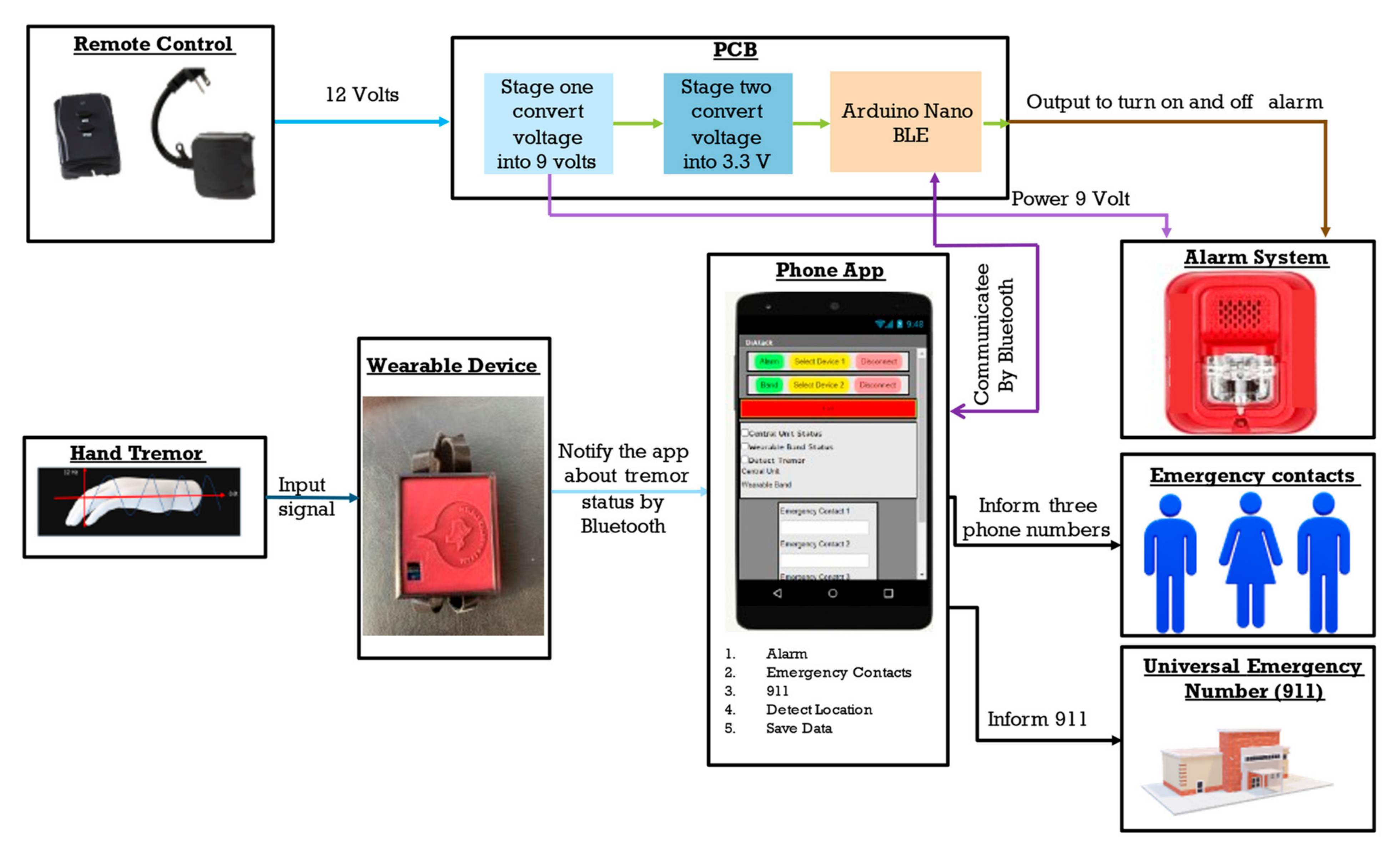
Figure 1. DiAtack Conceptual Block Diagram.
Inventions 07 00032 g001
Figure 2. DiAtack functional block diagram.
Inventions 07 00032 g002
Figure 3. DiAtach alarm control circuit.
Inventions 07 00032 g003
Figure 4. DiAtack Mobile Application.
Inventions 07 00032 g004
Figure 5. DiAtack wearable band software setting.
Inventions 07 00032 g005
Figure 6. DiAtack Central Unit Software setting.
Inventions 07 00032 g006
Figure 7. Accelerometer Direction.
Inventions 07 00032 g007
Figure 8. DiAtack wearable band. (A)—case, (B)—case cover, (C)—wearable device, (D)—wearing the wearable device and (E)—wearable device with its components.
Inventions 07 00032 g008
Figure 9. DiAtack Central Unit.
Inventions 07 00032 g009
Figure 10. DiAtack PCB.
Inventions 07 00032 g010
Figure 11. DiAtack Mobile Application.
Inventions 07 00032 g011
Figure 12. (a): X Data Detected from Wearable Device; (b): Y Data Detected from Wearable Device; (c): Z Data Detected from Wearable Device.
Inventions 07 00032 g012
Figure 13. (a): X Data convert from Time Domain to Frequency; (b): Y Data convert from Time Domain to Frequency; (c): Z Data convert from Time Domain to Frequency.
Inventions 07 00032 g013aInventions 07 00032 g013b
Figure 14. XYZ Filtered frequency data sent from the wearable band.
Inventions 07 00032 g014
Figure 15. XYZ Filtered frequency data received from the wearable band.
Inventions 07 00032 g015
Table 1. Product Test and Validation.
TestConditions to Pass
Visual
  • Check PCB with Altium Design
  • Check App Layout
  • Check buttons for scanning and connecting to both Microcontrollers
  • Show textboxes to allow numbers to be entered
  • Location is shown
  • A case encloses the battery and Arduino Nano 33
  • The wearable watch and band fits like a normal watch
Input and output voltage
  • 9.36 V > V to Microcontroller > 8.64 V
  • 3.366 V > V to Alarm > 3.234 V
  • 12.12 V > Voltage Input > 11.88 V
Output current
  • 130 mA > I to the Microcontroller > 100 mA
  • 119 mA > I to Alarm > 99 mA
MOSFET
  • Alarm Turn on when Microcontroller send Power to gate of MOSFET
  • Alarm off When Microcontroller sends power to gate of MOSFET
Functionality
  • Buttons function properly
  • Textboxes allow text to be entered
  • Mobile application does not crash at any point
BLE connection
  • App scans for BLE devices
  • App can connect to both Arduino Nano 33 s
Notification
  • App sends one text to each of the three emergency contacts
  • App sends one text automatically to a number programed in the code (normally 9-1-1)
  • Text message contains location from phone
  • Alarm activates light and sound once emergency protocol is entered
Data Storage
  • Check whether data saved on app
Publisher’s Note: MDPI stays neutral with regard to jurisdictional claims in published maps and institutional affiliations.