1. Introduction
The use of tracked feller-buncher machines is still one of the most popular means of mechanized tree felling. The reasons for such a decision are their low ground pressure (about 38–75 kPa) [
1] and high shift productivity (4–5 times higher than that of the harvester) [
2,
3] compared to wheeled logging equipment.
Forest machines are often operated on flat terrain and difficult terrain with various kinds of micro-irregularities or hilly terrain. In order to increase stability as well as operator comfort, tracked feller-buncher machines are equipped with a platform leveling system. About 55% of all modern machines are equipped with a leveling system, which indicates a high demand among loggers for this design element. This raises the problem of optimal design of the leveling system and the analysis of both positive and negative aspects of using such systems.
The subject of the research was a system of platform leveling—a hydraulic mechanism that converts the translational motion of the hydraulic cylinder rods in the rotational motion of the platform around the hinge axis. The platform can be rotated both in the longitudinal and transverse planes. Two-cylinder and three-cylinder assemblies are the most widespread.
John Deere (Moline, IL, USA), Tigercat (Cambridge, ON, Canada), and Komatsu Forest (Umeå, Sweden) are all equipped with a two-cylinder leveling system. In general, the two-cylinder leveling system consists of two hydraulic cylinders hinged to the rear frame of the machine, each of which is connected to a balancing valve designed for load retention and cross-pressure relief [
4]. Cylinder rod heads are secured by pins in eyes welded to the leveling unit. The equalizing unit consists of two mutually hinged plates. The lower plate is mounted on the front frame, which in turn is mounted on bearings in the machine hull. The upper plate is hinged to the lower plate and the hydraulic cylinders. The platform is bolted to the top plate. The dual-cylinder leveling system works as follows: To tilt the platform left/right, the left/right hydraulic cylinder compresses, and the right/left extends, with the platform rotating transversely relative to the leveling unit plate joint. For forward tilting, both hydraulic cylinders expand, and for backward tilting, the longitudinal rotation is relative to the front frame bearing axis.
In works [
5,
6,
7,
8], the studies aimed to investigate the influence of the added dynamic load acting on the elements of technological equipment, base, and power unit of the feller-buncher machine. The research results showed that introducing the platform leveling system into the design of the feller-buncher significantly increases the dynamic load on the machine in the process of its technological operations. In [
9], a study aiming to assess the impact of the platform leveling system on the vibration load of the feller-buncher machine operators was presented. There are known studies [
10,
11,
12,
13,
14,
15,
16,
17,
18,
19,
20,
21,
22,
23,
24,
25,
26,
27,
28] on the practical use of feller buncher machines with different leveling systems when harvesting timber on steep slopes.
It should be noted that these [
10,
11,
12,
13,
14,
15,
16,
17,
18,
19,
20,
21,
22,
23,
24,
25,
26,
27,
28] papers did not evaluate the design features of the leveling systems. Our work aimed to analyze the design features of the leveling systems, as well as to analyze the stability of feller-buncher machines with a leveling system to determine the limiting angles of static stability (when driving up a slope and in a transverse roll) without the use of auxiliary equipment such as winches or additional outriggers.
Our study aimed to evaluate the effectiveness of the existing platform leveling systems, taking into account the metal consumption of the equipment. The novelty of our study consists of the developed mathematical model, which allows the solving of the problem of determining the limiting angles of static stability of the feller-buncher with the platform leveling system in a general form. The study results can be used both in evaluating the stability of existing feller-buncher machines and in designing new models.
2. Materials and Methods
The study consists of five consecutive sections. Let us shortly examine what each of the sections is about and what their purposes are.
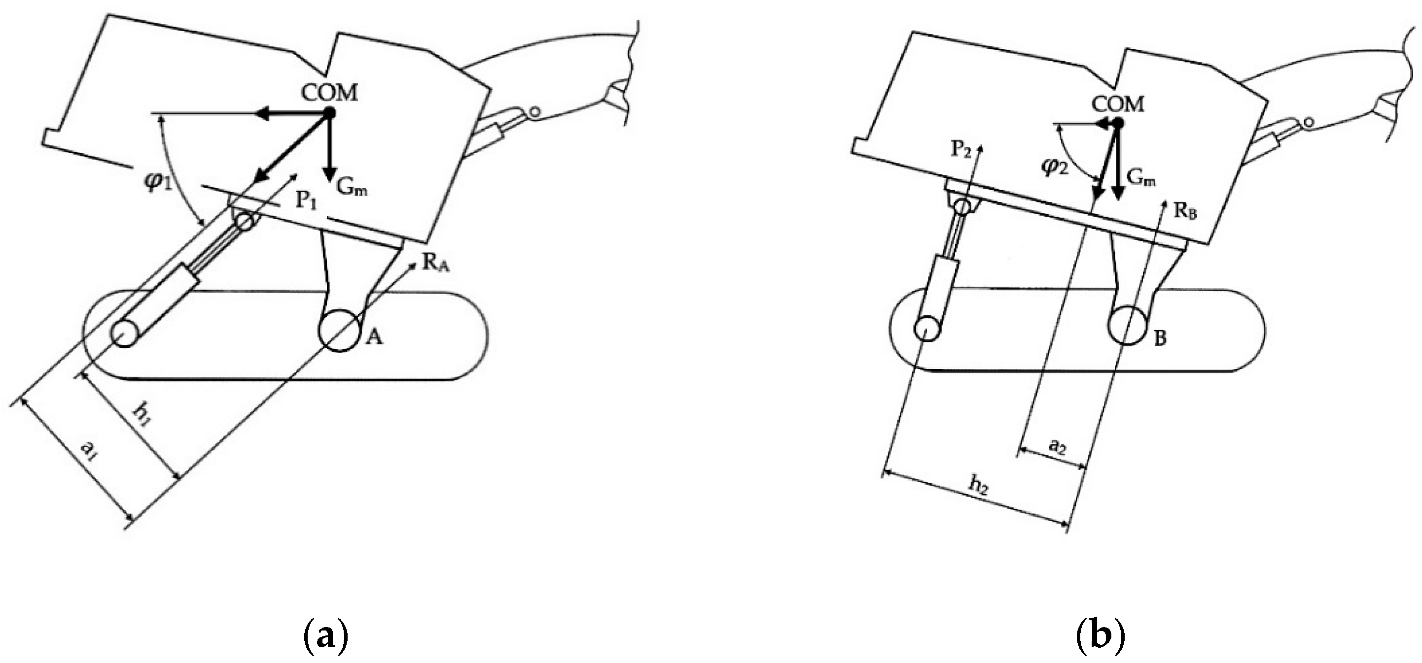
Section 3.1 discusses the two most common designs of platform leveling systems for tracked feller bunchers. In the first case under consideration, the platform is tilted by two hydraulic cylinders, and their action forces are directed to the platform center (
Figure 1a). In the second case, the platform is tilted by one hydraulic cylinder, and its force is directed to the edge of the platform (
Figure 1b). The purpose of this section is to determine in which of these two schemes the force on the hydraulic cylinder rods will be less and by how much.
Section 3.4 presents a diagram that shows the change in position of the center of mass of the feller-buncher when its platform is tilted (
Figure 2). A mathematical model shows how the position of the center of mass of the feller-buncher will change as a function of the angle of inclination of its platform. This section also gives a mathematical equation showing how the position of the center of mass of the base machine would change along the ordinate axis if a platform leveling system were to be incorporated into its design.
In
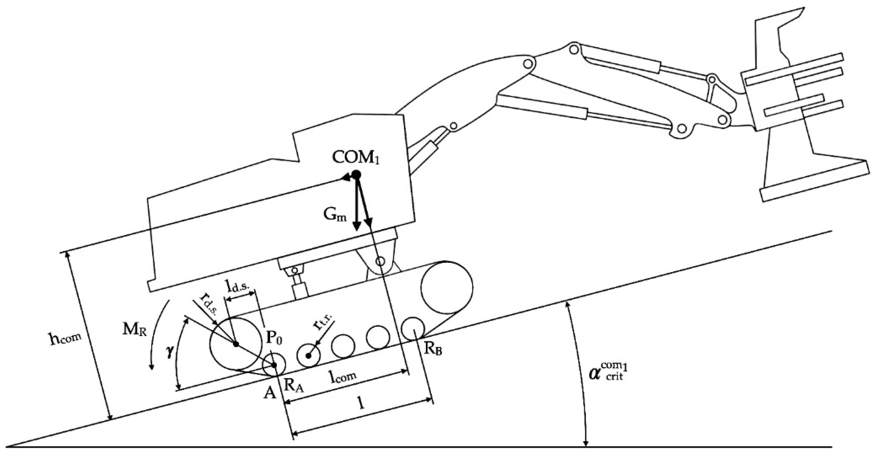
Section 3.3, we consider two computational diagrams that show the forces acting on the feller buncher while driving uphill. The first diagram (
Figure 3) shows the uphill motion of the feller-buncher without platform tilt, while the second diagram (
Figure 4) shows the uphill motion of the feller buncher with platform tilt. For each design case, mathematical expressions for determining the limiting angle of ascent were compiled. The purpose of this section is to obtain a mathematical model to determine how much the marginal angle of lift will change when the platform is tilted.
Section 3.4 presents a calculation diagram showing the forces acting on the feller buncher when it tilts (
Figure 5). The purpose of this section is to obtain a mathematical model to determine how much the roll angle will change when the platform is tilted sideways.
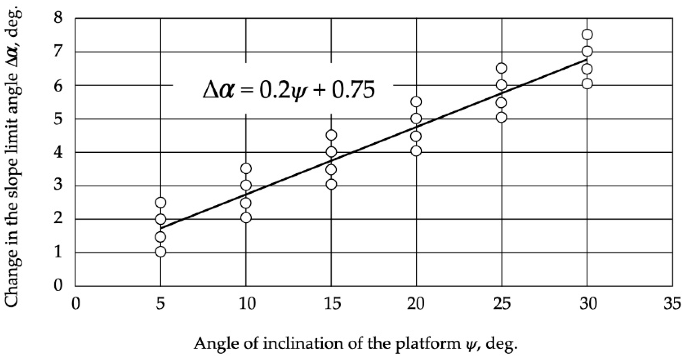
Section 3.5 presents graphs and regression equations showing: how would the marginal slope angle change depending on the platform tilt angle (
Figure 6); how the weight of the base machine would change if a platform leveling system were introduced into its design (
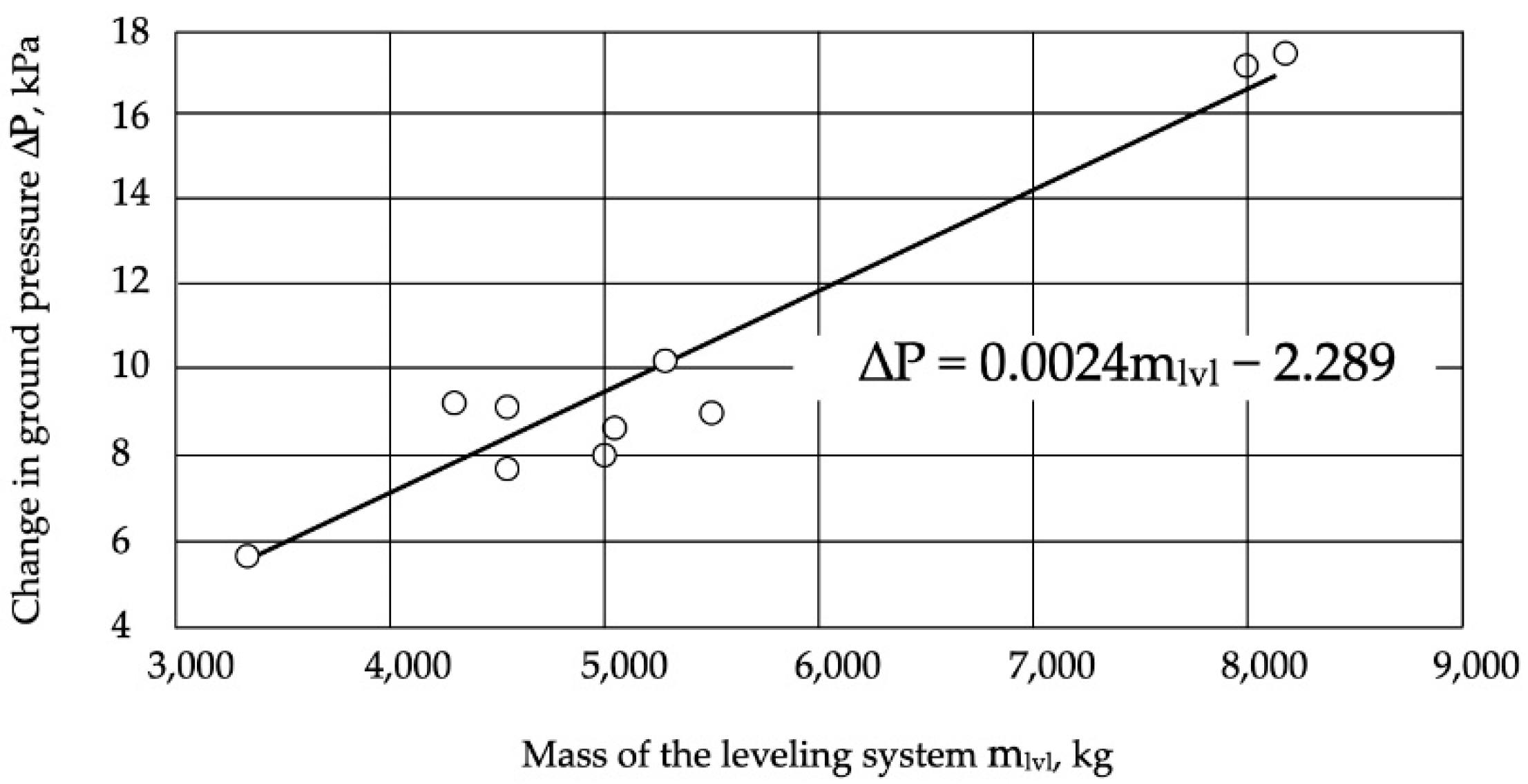
Figure 7); how would the ground pressure that a machine would create with a platform leveling system change as compared to the base machine (
Figure 8). The regression equations in this section were obtained from the data presented in
Table 1 (source of information: official websites of John Deere, Tigercat, Caterpillar) [
4,
29,
30,
31,
32,
33,
34,
35,
36,
37]. This section’s graphs and equations were obtained in Microsoft Excel according to the data presented in
Table 1. Significance levels of t-criterion and F-criterion for all three equations are less than 0.05, i.e., equations and their coefficients are 95% reliable.
To reproduce the results of the study, it is necessary to know the geometric and mass-dimensional parameters of feller-buncher machines. Some of the information can be found on the official websites of the companies producing the feller-buncher machines. The missing data can be obtained by direct measurements on the existing machine or set to design a new machine.
3. Results
3.1. Analysis of the Optimal Design of the Leveling System
The main parameters of the optimal layout of the leveling system can be taken as the force on the hydraulic cylinder rod of the platform tilt and the reaction of the pivot joint support. Let us consider the two most common layouts in the longitudinal plane, with the maximum tilt angle of the platform and the hydraulic cylinder rods fully extended (
Figure 1).
The force on the hydraulic cylinder rods can be determined by the following equations:
where
P—the force on the hydraulic cylinder rod, kN;
h—the lever arm on the hydraulic cylinder rod, m;
Gm—the machine gravity force, kN;
a—the arm of the equalizing force of gravity relative to the rotary joint axis, m;
φ—the angle of inclination of the hydraulic cylinder relative to the horizontal at the fully extended rod, deg; 1, 2—indices corresponding to two- and three-cylinder systems of alignment, respectively.
Converting expressions (1) and (2), we obtain:
The following equations can determine the bearing reactions in the joints:
By comparing schemes (a) and (b) (
Figure 1), the following patterns can be presented:
h2 >
h1;
a2 <
a1;
φ2 >
φ1 или
h2 =
k1h1;
a2 =
k2a1;
φ2 =
k3 φ1, where
k1 ≈ 1.5…2.0;
k2 ≈ 0.3…0.6;
k3 ≈ 1.4…2.0.
Then, by transforming expressions (3) and (4), we obtain:
Thus, from the point of view of forces on the hydraulic cylinders rods, at the stage of design, it is more reasonable to choose scheme (b) (
Figure 1), as although, at this configuration, only one hydraulic cylinder makes the platform tilt in the longitudinal plane, the force on its rod is about 50…60% less than those on each of the two hydraulic cylinders of scheme (a).
3.2. The Mathematical Model for Determining the Changes in the Position of the Center of Mass of the Feller-Buncher Depending on the Angle of Inclination of the Platform
Evaluating the forces on the hydraulic cylinder rods, we can see that it largely depends on the center of mass of the feller-buncher. There is a need for a mathematical description of its change depending on the platform inclination angle in this connection.
The change in the center of mass of the feller-buncher is caused by the tilting of a part of the machine mass (
Figure 2) located on the platform (swivel section), which includes the cabin with the engine and the hydraulic compartment, the boom, and the gripper-cutting device, while the center of mass of the undercarriage is not displaced.
Changing the position of the center of mass of the swivel section of the feller-buncher depending on the inclination angle of the platform occurs on an arc of a circle with the center on the axis of the rotary joint, the chord of which is the distance between the initial and the final position of the center of mass, and it is described by the expression:
where
R—the distance between the axis of the rotary joint and the initial position of the center of mass, m;
ψ—the angle of inclination of the platform, deg.
Usually, feller-bunchers equipped with the levelling system are designed on the basis of models similar in their characteristics, but without levelling (
Table 1). Therefore, when designing such systems, it is important to determine the change in center of mass position resulting from their addition to the design.
The greatest change in the center of mass will be on the vertical axis, as the overall height of the machine increases, as well as its mass. The shift along the horizontal axis can be considered insignificant, as there is no increase in the length of the machine, and the change in its mass falls on the lower elements of the structure (frame, hull, platform, etc.).
The added mass of the metal structure of the leveling system shifts the center of mass downward and its height upward. The position of the center of mass along the ordinate axis of the base machine is determined by the expression:
where
mund,
mcab,
mmb,
mob,
mfh and
yund,
ycab,
ymb,
yob,
yfh—masses and coordinates of centers of mass on vertical axis of the undercarriage, cabin, boom, arm, and gripper-cutting device, respectively, kg and m;
mm—mass of the base machine, kg.
The position of the center of mass on the axis of ordinates of the feller buncher with the leveling system is determined by the expression:
where
H—height of the leveling system, m;
ylvl—coordinate of the center of mass along the vertical axis of the leveling system, m;
mlvl—mass of the leveling system, kg.
Converting expression (10), we obtain:
3.3. The Mathematical Model for Determining the Limiting Angle of Slope of the Terrain When the Feller-Buncher Moves Up the Slope
Knowing the initial position of the center of mass of the feller-buncher with the leveling system and the law of its change from the inclination angle of the platform, it is possible to estimate the main task of the leveling system—increasing stability of the machine while working on a slope. The problem is reduced to finding the change in the terrain slope limit angle when tilting the platform by a certain angle.
Figure 3 shows the calculation scheme for determining the limiting angle of inclination of the terrain when the feller-buncher moves up the slope (without platform leveling).
The stability criterion can be taken as a zero reaction (
RB = 0), acting on the front support of the body [
38]. The equation of moments with respect to the tilt point A will be of the form:
where
l—distance between reactions of supports acting on the front and rear parts of the hull, m;
hcom—distance between center of mass and tipping point by height, m;
—slope angle limit in the absence of center of mass displacement, deg;
lcom—distance between center of mass and tipping point by length, m;
P0—tensioning power of tracks, kN;
rd.s.—radius of the leading sprocket, m;
rt.r.—radius of the track roller, m;
γ—angle of inclination of the rear track branch, deg;
ld.s.—distance between the center of the sprocket and the tipping point, m.
where
—coefficient of resistance to movement of the machine.
Substituting expression (13) in (12), we obtain:
Expressing
from Equation (14), we obtain:
Expression (15) can be simplified by discarding insignificant parts, which will cause an error of no more than 5%; the equivalent expression is as follows:
When the feller-buncher moves up a slope with a tilted platform (
Figure 4), the center of mass will shift (
Figure 2), and considering expression (15), it is necessary to determine the shift in the center of mass both in height and length relative to the tipping point.
As can be seen from
Figure 4, it is most appropriate to place the center of mass of the swivel section above the axis of the rotary joint because when the platform tilts forward/backward, the center of mass shifts closer to the top of the slope, which increases the stability of the machine both uphill and downhill. Thus, the displacement of the center of mass of the turning part can be reduced to the problem of finding the cathetuses of a right triangle COM
1COM
2C. Considering triangle BCOM
1COM
2, and seeing that it is isosceles, angle
β is equal to:
Then, the displacement of the machine’s center of mass relative to the tipping point along the length and height, respectively, taking into account the masses of the turning part and the machine mass, is defined by the expressions:
where
—the mass of the turning part, kg;
—the mass of the machine, kg.
Substituting Equations (8) and (17) into expression (18), we obtain:
Thus, the expression for determining the limiting angle of slope of the terrain when the platform is inclined will look like:
Then, the expression for the change in the slope limit angle will be as follows:
Similarly, the change in the limiting angle of the terrain when the feller-buncher descends the slope is determined.
3.4. Mathematical Model for Determining the Slope Angle Limit When the Feller-Buncher Is Tilting
Figure 5 shows a calculation diagram for determining the limiting angle of slope of the terrain when the feller-buncher is tilting.
Point A is the tipping point. The tipping condition is
RB = 0, so:
Converting expression (23), we obtain:
When the platform tilts and, consequently, the center of mass shifts, expression (24) taking into account Equations (19) and (20) will take the form:
Then, the change in the limiting angle of slope when the machine tilts will be:
3.5. Assessment of Efficiency of Application of Leveling System in Feller-Buncher Machine Design
Based on the data given in
Table 1, let us estimate the effect that the introduction of leveling systems into the design of feller-buncher machines has on the weight of the machines and the pressure on the ground. Tracked feller-bunchers without a leveling system are used on terrain with a slope limit angle of not more than 8–10° [
39].
Figure 6 shows a graph of the change in the terrain slope limit angle vs. the angle of inclination of the platform.
As can be seen from Diagram 6, the application of platform leveling systems in feller buncher designs allows the working on slopes with a slope angle 50…60% more than that without leveling. A regression equation was derived for a simplified, approximate estimate of the change in terrain angle depending on the platform slope angle:
The coefficient of determination R2 of the presented dependence is 0.91, which indicates the linear nature of the equation with a probability of 91%. Significance levels of the t-criterion and F-criterion are less than 0.05, i.e., equation and its coefficients are 95% reliable. The correlation coefficient was .
Thus, the application of platform leveling systems increases the stability of feller-buncher machines. However, it should be taken into account that when adding such systems, the weight of the machines inevitably increases (
Figure 7) and, consequently, the pressure on the ground (
Figure 8).
The introduction of leveling systems into the designs of feller-buncher machines increases their weight and, consequently, the pressure on the ground by 15…20%. For the approximate estimation of the weight of the designed feller-buncher with the leveling system, the equation of regression was received:
where
—the mass of the feller-buncher with a leveling system, kg;
mm—the mass of the base machine, kg.
To roughly estimate the added ground pressure caused by adding a leveling system to the feller-buncher design, a regression equation was obtained:
where Δ
P—the additional pressure on the ground, kPa;
mlvl—the mass of leveling system, kg.
Dependencies (28) and (29) are linear with determination coefficients of 0.61 and 0.92, respectively. The significance levels of t-criterion and F-criterion are less than 0.05 for both equations. The correlation coefficients were 0.76 and 0.96, respectively.
4. Discussion
Our study analyzed the effectiveness of using platform leveling systems in the designs of tracked feller-buncher machines. The analysis revealed a positive effect of using such systems when working on slopes, as the stability of the machines, achieved by changing the position of the center of mass when the platform is inclined, is increased. Mathematical models, presented in this work, allow the estimation of the limits of the slope angle depending on the inclination of the platform; however, it is necessary to take into consideration several limitations, which also have a significant impact on the stability of the machine and which were not taken into consideration in our proposed model, namely:
the weight of the gripper-cutting device;
parameters of the cut tree (center of gravity, weight, crown area, height, etc.)
arm’s reach at which the machine is working;
the strength of the wind impact on the cut tree;
soil and ground conditions.
The effect of these parameters on the stability of feller-buncher machines when working on slopes may be an essential issue for further research.
It is also worth noting that forestry machines working on steep slopes often do not develop sufficient traction to reach the limiting angle at which the machine will tip over [
13]. This issue is also quite interesting for further research related to finding an adequate mathematical model for determining the limiting angle of lift of the windrow buncher, limited by engine power and traction of the tracked mover with the soil.
The variation in values of the terrain slope parameter can be partially explained by the skillful operator’s control of technological equipment. Thus, the Tigercat LH845C tracked harvester was able to move up the slope with a slope up to 67% [
10]. Such an effect was achieved due to the extended boom of a manipulator, playing the role of counterweight, and skilled control of the machine in general. In our study, the primary role in determining the slope angle limit of the terrain was played by the design parameters of machines. The role of the operator in controlling the machine was not taken into account.
Sessions et al., 2017 [
17] considered the case of tethered feller-buncher motion to derive theoretical stability models with the assumption that both feller-buncher tracks are parallel to the slope and equally loaded. Our methodology adopts a similar assumption. In the real world, however, ideal flat slopes and equal loading of the tracks are rare. Solving the stability calculation problems in such cases will make it possible to design feller-buncher machines that are more resistant to rollover.
In cases when the operation of this type of machinery is supposed on steeper slopes (with a slope of more than 60%), the most expedient and safe solution is the use of a winch or chain, installed on one side to the machine chassis, and on the other to the growing trees, stumps, or auxiliary machine (bulldozer, excavator) [
11,
14,
16,
17].
5. Conclusions
Analysis of platform leveling systems showed the effectiveness of their application in the designs of tracked feller-buncher machines. These systems allow the machines to work on slopes 50…60% higher than without them.
The analysis of the layouts of tracked feller-buncher leveling systems has shown that, in terms of forces on the hydraulic tilt cylinder rods, preference should be given to the system with the greatest force leverage on the rod and the angle of inclination of hydraulic cylinders relative to the horizon. Thus, at the design stage, it is preferable to use a three-cylinder leveling system where one hydraulic cylinder, which works for tilting the platform in the longitudinal plane, meets the above requirements and the other two hydraulic cylinders work for transverse tilting of the platform.
Based on the proposed mathematical expressions, the optimal position of the center of mass of the rotary part is above the pivot, perpendicular to the axis of rotation and as low to the ground as possible from the position of stability. In this initial position, the center of mass shifts closer to the top of the slope as the platform tilts forward/backward. In this case, according to expressions (19) and (20), the greater the distance from the hinge axis to the center of mass, the greater its displacement to the top of the slope and, consequently, the higher the stability.
The mathematical expressions (22) and (26) allow us to determine changes in the limiting angle of slope of the terrain depending on the angle of inclination of the platform. The regression Equation (27) was obtained for approximate estimation.
The obtained regression expressions (28) and (29) make it possible to determine the weight of the designed feller-buncher with the leveling system based on the weight of the base machine and the added pressure on the ground caused by adding the leveling system to the design of the feller-buncher.
Author Contributions
Conceptualization, A.A.; methodology, B.I. and Z.I.; formal analysis, Z.I. and A.A.; investigation, B.I.; resources, B.I.; data curation, A.A. and Z.I.; writing—original draft preparation, A.A. and Z.I.; writing—review and editing, A.A. and B.I. All authors have read and agreed to the published version of the manuscript.
Funding
This research received no external funding.
Institutional Review Board Statement
Not applicable for studies not involving humans or animals.
Informed Consent Statement
Not applicable for studies not involving humans.
Conflicts of Interest
The authors declare no conflict of interest.
References
- Andronov, A.V.; Taradin, G.S.; Zverev, I.A. Models for the Determination of Basic Parameters of Tracked Feller Buncher Machines. IOP Conf. Ser. Mater. Sci. Eng. 2020, 817, 012001. [Google Scholar] [CrossRef]
- Andronov, A.V.; Zverev, I.A. Investigation of the Parameters Determining the Value of the Shift Productivity of a Feller-Bunchers. Izv. St. Peterbg. Lesotekhniceskoj Akad. 2020. [Google Scholar] [CrossRef]
- Orlov, A. Canadian Forest Machines in Russia. LesPromInform 2007, 2, 78–79. [Google Scholar]
- Tigercat 845C/L845C Feller Buncher: Service Manual; Tigercat Industries Inc.: Brantford, ON, Canada, 2011.
- Aleksandrov, V.A.; Aleksandrov, A.V. Modeling of Technological Processes of Forest Machines: Textbook, 3rd ed.; Lan: St. Petersbrug, Russia, 2016. [Google Scholar]
- Trusovtsev, D.S.; Alexandrov, V.A. Stress of the Feller Buncher in Stopping Modes during Platform Leveling. In Theoretical Foundations for Improving Forest Machines and Equipment; St. Petersburg State Forest Technical Academy: St. Petersburg, Russia, 2002; pp. 182–187. [Google Scholar]
- Gusev, V.A.; Aleksandrov, V.A. Stress of the Power Unit of the Feller Buncher in Stopping Modes during Platform Leveling. In Theoretical Foundations for Improving Forest Machines and Equipment; St. Petersburg State Forest Technical Academy: St. Petersburg, Russia, 2002; pp. 66–73. [Google Scholar]
- Aleksandrov, V.A. Stress of Feller Buncher Machines at Logging Sites; St. Petersburg State Forest Technical University: St. Petersburg, Russia, 2020. [Google Scholar]
- Aleksandrov, V.A.; Aleksandrov, A.V. Vibration Stress of Feller-Buncher Operators; St. Petersburg State Forest Technical University: St. Petersburg, Russia, 2017. [Google Scholar]
- McEwan, A.; Brink, M.; van Zyl, S. Guidelines for Difficult Terrain Ground Based Harvesting Operations in South Africa; Nelson Mandela Metropolitan University: Saasveld, South African, 2013. [Google Scholar]
- Visser, R.; Stampfer, K. Expanding Ground-Based Harvesting onto Steep Terrain: A Review. Croat. J. For. Eng. 2015, 36, 321–331. [Google Scholar]
- Schaare, R.; Harrill, H.; Visser, R. Tension Monitoring of Cable-Assisted Felling Machines; New Zealand Forest Research Institute Limited (Scion): Rotorua, New Zealand, 2016. [Google Scholar]
- Visser, R.; Raymond, K.; Harrill, H. Mechanising Steep Terrain Harvesting Operations. N. Z. J. For. 2014, 59, 3–8. [Google Scholar] [CrossRef] [Green Version]
- Amishev, J. Steep Slope Feller Buncher: A Feasibility Study; New Zealand Forest Research Institute Limited (Scion): Rotorua, New Zealand, 2011. [Google Scholar]
- Holzleitner, F.; Kastner, M.; Stampfer, K.; Höller, N.; Kanzian, C. Monitoring Cable Tensile Forces of Winch-Assist Harvester and Forwarder Operations in Steep Terrain. Forests 2018, 9, 53. [Google Scholar] [CrossRef] [Green Version]
- Leshchinsky, B.; Sessions, J.; Wimer, J. Analytical Design for Mobile Anchor Systems. Int. J. For. Eng. 2015, 26, 10–23. [Google Scholar] [CrossRef]
- Sessions, J.; Leshchinsky, B.; Chung, W.; Boston, K.; Wimer, J. Theoretical Stability and Traction of Steep Slope Tethered Feller-Bunchers. For. Sci. 2017, 63, 192–200. [Google Scholar] [CrossRef] [Green Version]
- Wong, J.Y.; Gao, Y. Applications of a Computer Aided Method to Parametric Study of Tracked Vehicles with Rigid Links. Proc. Inst. Mech. Eng. Part D J. Automob. Eng. 1994, 208, 251–257. [Google Scholar] [CrossRef]
- Wong, J.Y. Optimization of the Tractive Performance of Articulated Tracked Vehicles Using an Advanced Computer Simulation Model. Proc. Inst. Mech. Eng. Part D J. Automob. Eng. 1992, 206, 29–45. [Google Scholar] [CrossRef]
- Strandgard, M.; Alam, M.; Mitchell, R. Impact of Slope on Productivity of a Self-Levelling Processor. Croat. J. For. Eng. 2017, 35, 193–200. [Google Scholar]
- Parsons, N.J.; Gibson, H.G.; Ki, N. A Parametric Simulation Model for Analyzing the Performance of a Steel-Tracked Feller Buncher. J. Commer. Veh. 1999, 108, 79–86. [Google Scholar]
- Visser, R.; Berkett, H. Effect of Terrain Steepness on Machine Slope When Harvesting. Int. J. For. Eng. 2015, 26, 1–9. [Google Scholar] [CrossRef]
- Montorselli, N.B.; Lombardin, C.; Magagnotti, N.; Marchi, E.; Neri, F.; Picchi, G.; Spinelli, R. Relating Safety, Productivity and Company Type for Motor-Manual Logging Operations in the Italian Alps. Accid. Anal. Prev. 2010, 42, 2013–2017. [Google Scholar] [CrossRef] [PubMed]
- Miyajima, R.H.; Simões, D.; Fenner, P.T.; Batistela, G.C. The Impact of Felling Method, Bunch Size, Slope Degree and Skidding Area on Productivity and Costs of Skidding in a Eucalyptus Plantation. Croat. J. For. Eng. 2021, 42, 381–390. [Google Scholar] [CrossRef]
- Alam, M.; Acuna, M.; Brown, M. Self-Levelling Feller-Buncher Productivity Based on Lidar-Derived Slope. Croat. J. For. Eng. 2013, 34, 273–281. [Google Scholar]
- Arola, R.A.; Miyata, E.S.; Sturos, J.A.; Steinhilb, H.M. Felling and Bunching Small Timber on Steep Slopes; U.S. Department of Agriculture, Forest Service, North Central Forest Experiment Station: St. Paul, MN, USA, 1981.
- Atherton, J. The Potential Effects of Tethered-Based Forest Harvesting Systems on Soil Disturbance in Coastal British Columbia; University of British Columbia Library: Kelowna, BC, Canada, 2019. [Google Scholar]
- Acuna, M.; Skinnell, J.; Evanson, T.; Mitchell, R. Bunching with a Self-Levelling Feller-Buncher on Steep Terrain for Efficient Yarder Extraction. Croat. J. For. Eng. 2011, 32, 521–531. [Google Scholar]
- Tracked Feller Bunchers/Harvesters John Deere 900M/MH-Series Brochure; Deere & Company: Moline, IL, USA, 2020.
- Tracked Feller Bunchers/Harvesters John Deere 800M/MH-Series Brochure; Deere & Company: Moline, IL, USA, 2019.
- XT460L-3 Brochure; Komatsu America Corp: Chicago, IL, USA, 2015.
- 860C/870C/L870C/LX870C Feller Buncher Brochure; Tigercat Inc.: Brantford, ON, Canada, 2016.
- 855E/L855E Feller Buncher Brochure; Tigercat Inc.: Brantford, ON, Canada, 2018.
- 521B/522B Tracked Feller Bunchers and Harvesters Brochure; Caterpillar Inc.: Deerfield, IL, USA, 2013.
- 511/521/522/532 Tracked Feller Bunchers and Harvesters Brochure; Caterpillar Inc.: Deerfield, IL, USA, 2009.
- 541/551/552 Tracked Feller Bunchers and Harvesters Brochure; Caterpillar Inc.: Deerfield, IL, USA, 2009.
- 845E/L845E Feller Buncher Brochure; Tigercat Inc.: Brantford, ON, Canada, 2019.
- Aleksandrov, V.A.; Shol, N.R. Designing and Calculation of Machines and Equipment for Logging Operations and Lower Warehouses, 2nd ed.; Publishing House «Lan’»: St. Petersburg, Russia, 2012; ISBN 978-5-8114-1191-7. [Google Scholar]
- Sennikov, M.A.; Bachin, O.I. Tractors, Skidders and Units: Reference Catalog; Arkhangelsk State Technical University: Arkhangelsk, Russia, 2002. [Google Scholar]
| Publisher’s Note: MDPI stays neutral with regard to jurisdictional claims in published maps and institutional affiliations. |
© 2021 by the authors. Licensee MDPI, Basel, Switzerland. This article is an open access article distributed under the terms and conditions of the Creative Commons Attribution (CC BY) license (https://creativecommons.org/licenses/by/4.0/).


